1
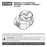
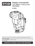
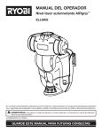
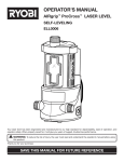
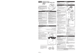
OPERATOR’S MANUAL
AIRgrip MultiTASKit™
EMM0001
Your product has been engineered and manufactured to Ryobi’s high standard for dependability, ease of operation, and
operator safety. When properly cared for, it will give you years of rugged, trouble-free performance.
WARNING: To reduce the risk of injury, the user must read and understand the operator's manual before using
this product.
Thank you for buying a Ryobi product.
SAVE THIS MANUAL FOR FUTURE REFERENCE
TABLE OF CONTENTS
n Introduction ..................................................................................................................................................................... 2
�n General Safety Rules ....................................................................................................................................................... 3
�n Symbols........................................................................................................................................................................ 4-5
�n Features........................................................................................................................................................................ 6-7
�n Assembly ......................................................................................................................................................................... 8
�n Operation.................................................................................................................................................................... 8-12
n Maintenance .................................................................................................................................................................. 13
n Troubleshooting ............................................................................................................................................................. 14
�n Parts Ordering / Service ................................................................................................................................................ 16
INTRODUCTION
This tool has many features for making its use more pleasant and enjoyable. Safety, performance, and dependability have
been given top priority in the design of this product making it easy to maintain and operate.
Please visit our website at
www.ryobitools.com to register this product.
Model No. EMM0001
2
GENERAL SAFETY RULES
n Always turn the laser level off when not in use. Leaving
the tool on increases the risk of someone inadvertently
staring into the laser beam.
WARNING!
READ AND UNDERSTAND ALL INSTRUCTIONS. Failure to follow all instructions listed below, may result in
electric shock, fire and/or serious personal injury.
n Do not operate the unit in combustible areas such as in
the presence of flammable liquids, gasses or dust.
n Always ensure the laser beam is aimed at a surface without reflective properties. Shiny reflective materials are not
suitable for laser use.
CAUTION:
n When using the base, always check to be sure the unit is
securely seated. Damage to the tool and/or serious injury
to the user could result if the unit falls.
Use of controls or adjustments or performance of procedures other than those specified herein may result in
hazardous radiation exposure.
n Handle the unit with care. Treat it as you would any other
optical device such as a camera or binoculars.
CAUTION:
n Avoid exposing the unit to shock, continuous vibration
or extreme hot or cold temperatures. Damage to the tool
and/or serious injury to the user could result.
The use of an optical instrument with this product will
increase eye hazard.
n The amount of weight being supported by the vacuum
base and/or helping hand should not exceed product
specifications. A greater weight may cause the product
to fail, which could cause damage to both the unit and
the workpiece being supported.
The laser guide radiation used in the laser level attachment
is Class IIIa with < 5mW and 635 nm wavelengths. These
lasers do not normally present an optical hazard, although
staring at the beam may cause flash blindness.
n Avoid direct eye exposure when using the laser and do
not project the laser beam directly into the eyes of others.
Serious eye injury could result.
n When using the magnetic base, be cautious of putting
too many or too heavy objects on the surface.
n Do not look directly into the LEDs on the lighting attachment. The brightness of the light could cause temporary
blindness.
n Do not remove or deface any product labels. Removing
product labels increases the risk of exposure to laser
radiation.
n Save these instructions. Refer to them frequently and
use them to instruct others who may use this product. If
you loan someone this unit, loan them these instructions
also.
n Do not place the unit in a position that may cause anyone
to stare into the laser beam intentionally or unintentionally.
Serious eye injury could result.
n Do not operate the laser level around children or allow
children to operate the tool. Serious eye injury could result.
3
SYMBOLS
Some of the following symbols may be used on this tool. Please study them and learn their meaning. Proper interpretation of these symbols will allow you to operate the tool better and safer.
SYMBOL
NAME
DESIGNATION/EXPLANATION
V
Volts
Voltage
A
Amperes
Current
Hz
Hertz
Frequency (cycles per second)
W
Watt
Power
Minutes
Time
Alternating Current
Type of current
Direct Current
Type or a characteristic of current
No Load Speed
Rotational speed, at no load
Class II Construction
Double-insulated construction
Per Minute
Revolutions, strokes, surface speed, orbits etc., per minute
Wet Conditions Alert
Do not expose to rain or use in damp locations.
Read The Operator’s Manual
To reduce the risk of injury, user must read and understand
operator’s manual before using this product.
Eye Protection
Always wear safety goggles, safety glasses with side shields, or
a full face shield when operating this product.
Safety Alert
Precautions that involve your safety.
No Hands Symbol
Failure to keep your hands away from the blade will result in
serious personal injury.
No Hands Symbol
Failure to keep your hands away from the blade will result in
serious personal injury.
No Hands Symbol
Failure to keep your hands away from the blade will result in
serious personal injury.
No Hands Symbol
Failure to keep your hands away from the blade will result in
serious personal injury.
Hot Surface
To reduce the risk of injury or damage, avoid contact with any
hot surface.
min
no
.../min
4
SYMBOLS
The following signal words and meanings are intended to explain the levels of risk associated with this product.
SYMBOL
SIGNAL
MEANING
DANGER:
Indicates an imminently hazardous situation, which, if not avoided, will
result in death or serious injury.
WARNING:
Indicates a potentially hazardous situation, which, if not avoided, could
result in death or serious injury.
CAUTION:
Indicates a potentially hazardous situation, which, if not avoided, may result
in minor or moderate injury.
CAUTION:
(Without Safety Alert Symbol) Indicates a situation that may result in property damage.
SERVICE
WARNING:
This unit has no serviceable parts. If the unit fails due to
normal wear and tear within two years of purchase, return
with original receipt for a replacement unit at no charge.
Call 1-800-525-2579 for your nearest RYOBI AUTHORIZED
SERVICE CENTER.
To avoid serious personal injury, do not attempt to use this
product until you read thoroughly and understand completely the operator’s manual. Save this operator’s manual
and review frequently for continuing safe operation and
instructing others who may use this product.
SAVE THESE INSTRUCTIONS
5
FEATURES
PRODUCT SPECIFICATIONS
Vacuum Base
Recommended Use................................................................................................................................................ Indoors
Power Supply .................................................................................................................................2 AA, 1.5 Volt Batteries
Battery Life ...................................................................................................4 Hours Continuous Use - Alkaline Batteries
Operating Temperature................................................................................................................................. 32°F to 104°F
Weight Capacity .......................................................................................................................................................15 lbs.
Laser Head
Length of Laser Line......................................................................................................................................... Up to 30 ft.
Laser......................................................................................................................................... Class IIIa, < 5mW, 635 nm
Power Supply .................................................................................................................................2 AA, 1.5 Volt Batteries
Battery Life .................................................................................................40 Hours Continuous Use - Alkaline Batteries
Accuracy....................................................................................................................................................± 1/2 in. at 20 ft.
Lighting Head
Power Supply .................................................................................................................................2 AA, 1.5 Volt Batteries
Battery Life .................................................................................................30 Hours Continuous Use - Alkaline Batteries
Helping Hand
Weight Capacity .......................................................................................................................................................12 lbs.
Extension Capacity.......................................................................................................................................................3 in.
ATTACHMENT
ON/OFF
BUTTON
LIGHTING
ATTACHMENT
LOCKING KNOB
ATTACHMENT
ON/OFF
BUTTON
HELPING HAND
ATTACHMENT
ATTACHMENT
RELEASE
BUTTON
AIRGRIP™
VACUUM
BASE
LOCKING
KNOB
LASER LEVEL
ATTACHMENT
MAGNETIC TRAY
ATTACHMENT
BASE ON/OFF
BUTTON
6
TAPE MEASURE
SLOTS
Fig. 1
FEATURES
MULTI-FUNCTION
BASE
CASE
HOOK-AND-LOOP
STRAP
ROUGH-SURFACE
ADAPTOR
Fig. 2
KNOW YOUR MULTITASKIT™
LASER LEVEL ATTACHMENT
See Figures 1 - 2.
Before attempting to use this product, familiarize yourself
with all operating features and safety rules.
The laser level attachment emits a laser line of up to 30 feet
and can be rotated 360˚.
LIGHTING ATTACHMENT
AIRGRIP™ VACUUM TECHNOLOGY
The lighting attachment has three medium-intensity LED
lights to provide light in dark work areas. It can be adjusted
vertically up to 90˚ and rotated horizontally 360˚.
This product uses a vacuum base that can adhere to smooth
surfaces. Using the vacuum seal prevents wall damage
caused by nails or adhesive tape. The vacuum base is used
to hold the MultiTASKit™ attachments and will support a
weight of up to 15 lbs. Recessed grooves on the base can
be used for attaching the end of a chalk line, and side slots
are available for holding the end of a tape measure.
MAGNETIC TRAY ATTACHMENT
CASE
The magnetic tray attachment can be used for holding screws,
nuts, and bolts. It features two holes for holding screwdrivers or other small tools, and has a recessed front edge so
tools can lie flat on the surface. The tray can be adjusted
90˚ vertically and 360˚ horizontally.
A zippered fabric case stores and protects the tool and accessories when not in use.
MULTI-FUNCTION BASE
Use the helping hand attachment to assist in holding small
amounts of weight up to 12 lbs. The hand can be extended up
to 3 in. and will rotate 360˚ horizontally and 35˚ vertically.
The multi-function base allows the unit to be used on irregularly shaped walls or objects. It features built-in loops for a
hook-and-loop strap and magnetic sides to hold securely
to magnetic surfaces. The base also protects the unit when
using on a dusty or dirty surface and during storage.
HOOK-AND-LOOP STRAP
ROUGH-SURFACE ADAPTOR
The hook-and-loop strap can be used along with the multifunction base to attach the unit to a variety of irregularly
shaped surfaces.
The rough-surface adaptor increases the number of surfaces
on which the AIRgrip vacuum can be used.
HELPING HAND ATTACHMENT
7
ASSEMBLY
UNPACKING
WARNING:
This product has been shipped completely assembled.
If any parts are missing, do not operate this tool. Please
return to the place of purchase or call 1-800-525-2579
for assistance.
n Carefully remove the tool and any accessories from the
box. Make sure that all items listed in the packing list are
included.
n Inspect the tool carefully to make sure no breakage or
damage occurred during shipping.
n Do not discard the packing material until you have carefully inspected and satisfactorily operated the tool.
n If any parts are damaged or missing, please call
1-800-525-2579 for assistance.
WARNING:
Do not attempt to modify this tool or create accessories not recommended for use with this tool. Any such
alteration or modification is misuse and could result in a
hazardous condition leading to possible serious personal
injury.
PACKING LIST
Vacuum Base
Multi-function Base
Laser Level Attachment
Lighting Attachment
Magnetic Tray Attachment
Helping Hand Attachment
4 AA Batteries
Hook-and-Loop Strap
Rough Surface Adaptor
Case
Operator’s Manual
�NOTE: Before initial use, wipe the AIRgrip seal with a damp
cloth to remove any residue.
OPERATION
INSTALLING BATTERIES IN VACUUM BASE
WARNING:
See Figure 3.
The battery compartment is located beneath the ridged area
of the vacuum base.
To open:
n Pull the battery cover out to remove.
Do not allow familiarity with tools to make you careless. Remember that a careless fraction of a second is
sufficient to inflict serious injury.
n Install two AA batteries according to polarity indicators
inside the battery compartment.
WARNING:
Do not use any attachments or accessories not recommended by the manufacturer of this tool. The use of attachments or accessories not recommended can result
in serious personal injury.
n Place the battery cover plate back onto the base and
secure.
VACUUM
BASE
APPLICATIONS
You may use this tool for the purposes listed below:
COVER
PLATE
n Single-person measuring
n Hanging pictures
n Aligning electrical outlets or ceiling lights
n Holding small screws and tools
n Installing towel bars, curtains, etc.
n Installing chair rail and crown molding
n Laying tile, flooring, or wallpaper
n Holding a chalk line in place
BATTERY
COMPARTMENT
n Temporary lighting under sinks, in closets, and for cars
n Simplifying two-person jobs to one person
8
Fig. 3
OPERATION
TURNING THE VACUUM BASE ON/OFF
See Figure 4.
Press the button located on the side of the vacuum base
to turn it ON and OFF. Always wait for at least 5 seconds
between stopping and restarting the unit.
USING THE AIR-GRIP™ VACUUM BASE
PUSH THE ON/OFF
BUTTON TO TURN
THE VACUUM BASE
ON OR OFF
See Figures 5 - 6.
Vacuum grip technology allows the unit to be attached to
most smooth surfaces.
NOTE: The multi-function base is not used when mounting
by vacuum grip.
n Place the unit on the surface you want it secured to and
push against the surface slightly to engage the seal.
n Continue to hold the unit against the surface while pressing the on/off button.
n Release the unit when you hear a change in motor
sound.
n To release the vacuum seal, turn the power to the vacuum
base off. For fast release, press the protrusion on the back
of the unit.
Fig. 4
PUSH IN SLIGHTLY
TO SEAL
NOTE: Pulling the unit off the wall without releasing the
vacuum could damage the tool.
The grooves located in the vacuum base can be used
to help hold a tape measure or chalk line when working
unassisted.
Fig. 5
ROUGH-SURFACE ADAPTOR
See Figure 7.
By using the rough-surface adaptor, you can use the AIRgrip
feature to position the unit on many non-smooth surfaces,
including brick and painted cinder block.
NOTE: The AIRgrip feature cannot be used with stucco or
unpainted cinder block.
n Position the rough-surface adaptor on the surface where
you want to secure the vacuum base.
NOTE: The dotted lines on the adaptor should be
visible.
n Place the unit against the adaptor on the dotted lines,
and push in slightly to engage the seal.
n Continue to hold the unit against the surface while pressing the on/off button.
n Release the unit when you hear a change in motor
sound.
TAPE MEASURE
GROOVES
Fig. 6
ROUGH-SURFACE
ADAPTOR
Fig. 7
9
OPERATION
USING THE MULTI-FUNCTION BASE
See Figures 8 - 9.
To use the hook-and-loop strap or magnetic mounts, the
multi-function base must be installed. To install the base:
n While holding the vacuum base with the on/off button
facing you, align the raised ridge on the multi-function
base with the groove on the vacuum base.
n Slide the two completely together.
NOTE: If the multi-function base is seated correctly, the
vacuum will not operate when the power is turned on.
HOOK-AND-LOOP STRAP: The strap can be used to attach the base to irregularly shaped objects such as pipes,
2x4s, 2x6s, or metal grates.
To install the strap:
n Attach the strap to one side of the multi-function base
by threading it through the loop and fastening.
RAISED RIDGE
GROOVES
MULTI-FUNCTION
BASE
VACUUM BASE
MULTI-FUNCTION
BASE
n Position the unit on the surface where you want it
mounted.
Fig. 8
MAGNETS
LOOP
n Wrap the strap around the object being mounted (pipe,
board, etc.).
n Place the loose end of the strap through the remaining
loop on the base and secure.
CAUTION:
HOOK-AND-LOOP
STRAP
Use caution when using the multi-function base. Do not
orient the unit in a way that will allow the vacuum base
to slide or fall out of the multi-function base.
BOTTOM OF
MULTI-FUNCTION
BASE
Fig. 9
ATTACHMENT
BASE
MAGNETIC MOUNTS: The magnetic mounts of the multifunction base allow the unit to be attached securely to
magnetically attracted metal surfaces.
INSTALLING BATTERIES IN THE LASER
LEVEL AND LIGHTING ATTACHMENTS
See Figure 10.
The laser level and lighting attachments are powered independently from the vacuum base. Each attachment requires
two AA batteries to operate.
To install batteries:
n Press the battery compartment access button on the laser
or lighting attachment to separate top of attachment from
attachment base.
BATTERIES
n Install batteries according to the polarity indicators in the
compartment.
BATTERY
COMPARTMENT
ACCESS
BUTTON
Fig. 10
n Reinstall attachment base. When secure, battery access
button will click back into place.
10
OPERATION
REMOVING/INSTALLING ATTACHMENTS
See Figure 11.
To install an attachment on the vacuum base, align the locking tabs on the desired attachment to the openings on the
vacuum base so the molded-in arrow is directly centered
above the battery door. Seat the attachment on the base and
rotate until you hear the attachment click into place.
To remove an attachment from the base, depress the release
button on the top of the base, twist the attachment until the
locking tabs on the attachment are aligned with the openings
in the base, then lift to remove.
ATTACHMENT
ARROW
LOCKING
TABS
ATTACHMENT
RELEASE
BUTTON
VACUUM
BASE
Fig. 12
Fig. 11
USING THE LASER LEVEL ATTACHMENT
See Figures 12 - 13.
The laser level attachment will project a straight line across
an obstruction or interference. The line can be rotated 360
degrees by turning the laser attachment in a clockwise or
counterclockwise direction. Re-level the unit for each wall,
adjacent surface, or direction a line is generated towards.
n Place the level in the area where you want the laser line
projected.
n If a true horizontal line is desired, level the tool by centering the bubbles inside the vials located on top of the laser
attachment.
NOTE: To ensure plumb lines, level vial and position the
tool directly in front of the work area.�
n Press the on/off button located on top of the laser level
attachment to turn the laser level on.
n Rotate the laser level attachment to position the laser line
where needed.�
NOTE: Due to construction inaccuracy, walls may not be
perfectly straight. This may cause the laser to have slight
variances when in the level position.
Fig. 13
11
OPERATION
USING THE LIGHTING ATTACHMENT
See Figure 14.
The lighting attachment uses three medium-intensity LED
lights to provide extra illumination in dark workspaces. The
light beam can be adjusted up to 90˚, and the lighting attachment can be rotated 360˚. Turn the lights on and off by
depressing the on/off button located on top of the attachment.
USING THE MAGNETIC TRAY ATTACHMENT
See Figure 15.
Position the tray in a horizontal or vertical position and tighten
the locking knob to secure in place. The magnetic surface
will hold small tools and/or nuts, bolts, screws, etc. The
small holes on the tray can be used to hold screwdrivers or
other cylindrical tools.
LIGHTING
ATTACHMENT
IN VACUUM BASE
USING THE HELPING HAND ATTACHMENT
See Figure 16.
The helping hand attachment will support a workpiece of up
to 12 lbs. The angle of the helping hand can be adjusted up
to 35˚ and is secured in place using the locking knob. The
length of the arm can be adjusted up to 3 in. by loosening
the center screw, sliding the arm up or down as desired,
then retightening the center screw to secure.
Fig. 14
MAGNETIC TRAY
ATTACHMENT
WARNING:
Do not use the helping hand to support anything weighing more than 12 lbs. Failure to heed this warning could
cause serious personal injury.
LOCKING KNOB
Fig. 15
HELPING HAND
ATTACHMENT
LOCKING
KNOB
LOCKING
KNOB
12
Fig. 16
MAINTENANCE
�n To clean the laser lens and lighting lens, if needed, use
ONLY a soft cloth or cotton swab moistened with glass
cleaner.
WARNING:
To avoid serious personal injury, always remove the
batteries from the tool when cleaning or performing any
maintenance.
n Check the batteries regularly to avoid deterioration. Remove the batteries from the vacuum base, laser attachment, and/or lighting attachment, if you will not be using
them for an extended time.
GENERAL MAINTENANCE
�n Do not disassemble the laser level attachment. This could
cause exposure to hazardous laser radiation.
n Before initial use, wipe AIRgrip vacuum base with a damp
cloth to remove any residue.
n Do not attempt to change any part of the laser lens.
n Store the unit indoors.
n When not in use, the vacuum base and attachments
should be kept in the protective case.
WARNING:
Do not at any time let brake fluids, gasoline, petroleumbased products, penetrating oils, etc., come in contact
with plastic parts. Chemicals can damage, weaken, or
destroy plastic, which may result in serious personal
injury.
n Keep the unit free of dust and liquids. Use a damp cloth
and mild soap to clean the outside casing. Avoid using
solvents when cleaning plastic parts. Most plastics are
susceptible to damage from various types of commercial
solvents and may be damaged by their use.
ALWAYS BE AWARE of the location
where the laser light is emitted when
using the laser level attachment. ALWAYS MAKE SURE that any bystanders
in the vicinity of use are made aware of
the dangers of looking directly into the
laser beam.
13
TROUBLESHOOTING
Problem
Vacuum not running
Possible Cause
Solution
Batteries are low
Replace batteries.
Power is turned off
Press on/off button.
Laser line projection is weak
Batteries are low
Replace batteries.
Laser line is hard to see
Light in area is too bright
Dim light in the work area or use
laser-enhancing glasses.
Light is not working
Power is not “on”
Press the on/off button.
Batteries are low
Replace batteries.
Leveling bubbles not properly aligned
Make sure bubbles are centered in
vials.
Level is mounted on base that is not
level
Make sure bubbles are centered in
vials after installing multi-function
base onto vacuum base.
Light is dim
Batteries are low
Replace batteries.
Magnetic tray isn’t holding items
Items are not placed on the magnet
Put items in the center of the tray
where magnets are located.
Magnetic tray is loose or won’t stay
in position
Handle isn’t tight
Rotate the height adjustment screw
clockwise to tighten.
Magnetic tray is too tight/won’t
move
Handle is tight
Rotate the height adjustment screw
counterclockwise to loosen.
Helping hand is loose
Screws not tight
Rotate the locking knob clockwise
to secure in position.
Vacuum base won’t stick to wall
Surface is incompatible for vacuum
Use rough-surface adaptor on
stucco and textured surfaces.
Laser line is not level
14
NOTES
15
OPERATOR’S MANUAL
AIRgrip MultiTASKit™
EMM0001
• SERVICE
This product has no serviceable parts. If unit fails due to normal wear and tear within two
years of purchase, return with original receipt for a replacement unit at no charge. Please
call 1-800-525-2579 for the nearest Ryobi Authorized Service Center. You can also check
our web site at www.ryobitools.com for a complete list of Authorized Service Centers.
• MODEL NO.
The model number of this tool will be found on a label attached to the top of the laser
head. Please visit our website at www.ryobitools.com to register this product.
• HOW TO ORDER REPLACEMENT PARTS
When ordering replacement parts, always give the following information:
•
MODEL NUMBER
EMM0001
RYOBI TECHNOLOGIES, INC.
1428 Pearman Dairy Road, Anderson, SC 29625
Post Office Box 1207, Anderson, SC 29622-1207
Phone 1-800-525-2579
www.ryobitools.com
983000-801
7-05
16