1
US 20020029097A1
(19) United States
(12) Patent Application Publication (10) Pub. No.: US 2002/0029097 A1
Pionzio, JR. et al.
(43) Pub. Date:
(54)
WIND FARM CONTROL SYSTEM
(76)
Inventors: Dino J. Pionzio J R., Barcelona (ES);
Curt W. Peterson, Marina Del Rey, CA
Mar. 7, 2002
Publication Classi?cation
(51)
(52)
(US); David L. Barnes, Alpine, CA
(US); William J. Libby, San Diego,
CA (US); Mark I. Lee, Zurich (CH);
Int. Cl.7 ................................................... .. G05D 11/00
US. Cl. .......................................... .. 700/286; 700/287
(57)
ABSTRACT
Benjamin Reeve, Arlington, MA (US)
Correspondence Address:
A Supervisory Command and Data Acquisition (SCADA)
HANS R_ TROESCH
system for managing Wind turbines for electric poWer gen
Fish & Richardson P_C_
eration. One implementation includes a SCADA element at
Suite 100
2200 Sand Hill Road
Menlo Park, CA 94025 (Us)
each Wind turbine, con?gured to collect data and provide an
interface to control the turbine and communicate With other
parts of the system; a SCADA element at a substation,
con?gured to collect data from the substation, to commu
(21) APPL NO;
09$28,500
(22)
Apt; 6, 2001
nicate With other parts of the system, and to store substation
data locally; a SCADA element at each meteorological site,
con?gured to collect meteorological data from sensors on
Related US, Application Data
and at a meteorology toWer, to communicate With other parts
of the system, and to store meteorology data locally; a data
(63) Non-provisional of provisional application No.
60/207,722, ?led on May 26, 2000. Non-provisional
With the Wind turbines, the substation, and the meteorologi
cal sites through their respective the SCADA elements; and
Filed;
communication network; a server coupled over the network
of provisional application No. 60/195,743, ?led on
a user interface through Which authoriZed users can exercise
Apr. 7, 2000.
command and control functions.
30 I’
,
—
-
-
—
—
—
10:
l
\\ Array _
: prqcessmg
-
—
-
—
-
-
—
—
—
-
\
i
,~~--_ "699‘
l
|
:
i
| Operations and :
: Maintenance I
\PE"_(L‘\_PL_')_ ________ , _ J
I
(0&M) Site
1
|
I
i
i
i
i
i
I
|
I
|
l
|
mast
l
|
l
\
‘Meteorological sites
Turbine sites
\
_
_
_
_
_
_
_
_
_
_
_
_
_
_
_
_
____,
Patent Application Publication
FIG. 1A
Mar. 7, 2002 Sheet 1 0f 6
US 2002/0029097 A1
------------------
‘I
|
/_—_—— ——C_8g]
l
\ Array _
: Prqcesslng
|
:
,
| Operations and 1
1 Maintenance 1
\ 991g (5_Pl_J>_ ________ __,I
I
(0&M) Site
1
|
\ _
_
_
_
_
_
_
_
__
_,I
{A
____f 50
32
SPU |—| Substation {
40
f
_
_
_
_
_
_
_
_
_
_
_
_
_
_
_
_
|
I
I
‘ :
:
i
_
_
43
l
'
_
| MPU |_/
MPU
Met
42
Met J
mast
mast
J
“
"I
I
i
g
l
|
1
Wind
:
:
I
:
l
turbine
l
i
'
|
:
'
'?ef‘iolologlxlts?is _______ _ _,'
63
63
/ 62
I
/ 62
:
i w Wmd
:
turblne
;
:
I
|
I
I
l
1
Turbine sites
|
|
|
1
|
I
|
I
1
I
|
|
|
|
|
r
|
1
\
Patent Application Publication
f p
_ _ _ —
_
_ _ _ _ _ _ _ _
I
Mar. 7, 2002 Sheet 2 0f 6
— _ _ _ _ _ —_\
US 2002/0029097 A1
/_———___£_89—__:_\
Substation Site I
I
081M Site |
|
l
:
l
I
|
I
I
l
1
i
I
l
l
I
I
1
I
I
I
:
I
l
: I
I
'
|
|
|
.,
Modem
(optional)
l
I
I
|
i
I
l
mun
/ 54
i
1:1
I
D
I
|
Slave
I
l Workstation
I
I
I
I
I
l
I
\ 31
l
I
l Substation
I
I
I
I
I
I
I
I
I
I
Controller
\
To turbine and
meteorological sites
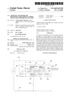
FIG. 1B
70
Patent Application Publication
t/\/240
Optical Fiber
k
r
l
|
|
l
Premise
l
1
Box
200
Mar. 7, 2002 Sheet 3 0f 6
US 2002/0029097 A1
Vaisala PTB101 B
Sensors
Pressure Sensor
SDM-8 Multiplexor
|
\
l
l
/-43
I
‘
-
:
r320
CR10X Logger
Turbine
Processing
|
l
l
l
Unit (TPU)
RS 232
|
‘ r350
|
I
1
|
1
Power
| /-340
/— 220
:
Black Box
Async F0
Mini Modern
Turbine Controller
l
l
l
l
\
Turbine tower
_
_
_
_
_
_
_
_
_
_
_
_
_
_
_
____,
Battery
and
Charger
l
F0 cable
FIG. 4
Patent Application Publication
Mar. 7, 2002 Sheet 4 0f 6
r310
r311
US 2002/0029097 A1
r312
42
NRG 20OP
RM Yount 2716GT
NRG Type 40
Wind Direction
Vertical Wind Speed
Horizontal Wind
J
Sensor
Sensor
Speed Sensor
40 Meters AGL
W313
/—314
(Above Ground
NRG
NRG
Level)
20OP
Type 40
30 Meters AGL
NRG
200P
NRG
Type 40
20 Meters AGL
/-318
r317
Campbel 107
r319
NRG
Temperature
NRG
200P
Sensor
Type 40
320
Logger
J
w
10 M
6ters AGL
Serial comm over
fiber optic
l
/
43
Transformer
Fiber Modem
220 V AC
HUB
FIG. 3
Network
Patent Application Publication
Mar. 7, 2002 Sheet 5 0f 6
US 2002/0029097 A1
220
5
Turbine
controller
/- 42
510
/_
Met Mast
LC“:
PLC
T
/- 43
MPU
RSLinx
63
/_
TPU
I
RECIFzSocket:
MMIF
Ethernet
/- 10
680
7
RS SQL
520
MM Listener
TPU Control
DBIF:
RECIF:
NamedPipe
NamedPipe
66°
DBIF:
NamedPlpe
Repositmy
DB|F:NamedPipe
DBIF:
I
SocketEthernet
( Alarms J
A
l ______________________________ _ —_i
SMSIF:Ethernet
’
l
||
pager
E-mail
I
‘
g
|
1
|_
Removable
Storage
_
_
_
_
_
_
_
_
_
_
@A
‘
_
_
_
_
__
=
I
a.’
'
:
|
l
Patent Application Publication
Mar. 7, 2002 Sheet 6 0f 6
US 2002/0029097 A1
FIG. 6
630
620
Data
Processing
Agent
610
640
Remote
Access
(TPU, GUI)
660
SPU
Control
680
670
650
Mar. 7, 2002
US 2002/0029097 A1
WIND FARM CONTROL SYSTEM
from the elements at regular intervals and to perform data
base management on the received data, and to gather and
RELATED APPLICATIONS
maintain detailed current and historical data as to the inputs,
[0001] The present application claims priority to US.
Patent Applications No. 60/207,722, ?led May 26, 2000, and
No. 60/195,743, ?led Apr. 7, 2000. In the United States, the
priority claim is made under 35 U.S.C. § 119(e) and the
disclosures of the priority applications are incorporated here
by reference.
operating conditions, and outputs of all turbines of the Wind
farm at a high degree of time resolution.
[0007]
The invention can be implemented to realiZe one or
more of the folloWing advantages. Aperson Working on any
part of the Wind poWer system can use a portable device to
connect to a local controller, such as a turbine processing
unit at a turbine site, through a direct connection, such as an
BACKGROUND OF THE INVENTION
RS232 interface, and through the controller communicate
With any other component of the system through the user
[0002] The invention relates to SCADA (Supervisory
Command and Data Acquisition) systems in the context of
commercial electric poWer generation.
interface of the system. Acontroller can be connected to the
[0003] A Wind farm of Wind turbines operated for com
mercial electric poWer generation requires a considerable
infrastructure to support control and monitoring functional
ity of the Wind turbines and utility interconnect. In general,
system through any interface that supports TCP/IP (Trans
mission Control Protocol/Internet Protocol). Local storage
of data provides fault tolerant data acquisition, ensuring no
loss of data. The use of con?guration databases alloWs an
operator to perform real-time system con?guration Without
interfering With system operation. For eXample, system can
continue to monitor and process data While an operator is
the manufacturers of Wind turbines offer only Wind turbine
controllers and related command and control systems that
are speci?c to their turbine products. Such offerings gener
ally provide little or no means for integrating the products or
With any other program products that can access the data
systems of one manufacturer With those of another. Such
bases of the system.
offerings also generally provide only an engineering vieW of
the operation of a Wind farm rather than a business or
?nancial vieW.
adding or subtracting turbines from the system database.
[0008] The design also alloWs for seamless integration
[0009] Because system reliably gathers and maintains
detailed current and historical information as to the inputs,
Thus, there is a need for a SCADA system that can
operating conditions, and outputs of all components at a high
degree of time resolution, the system provides the detailed
be used in a cost effective and ef?cient manner to operate a
information needed for predictive analysis, performance
reliable and pro?table Wind farm.
analysis, and model design and veri?cation for a variety of
model types, such as ?nancial, air?oW, process, and
mechanical.
[0004]
SUMMARY OF THE INVENTION
[0005]
In general, in one aspect, the invention provides a
[0010] Having computing and data storage resources in
Supervisory Command and Data Acquisition (SCADA) sys
the on-site controllers such as the turbine processing units
tem for managing Wind turbines for electric poWer genera
tion. One implementation includes a SCADA element at
trol functions to be performed in a highly scalable Way and
each Wind turbine, con?gured to collect data and provide an
interface to control the turbine and communicate With other
parts of the system; a SCADA element at a substation,
con?gured to collect data from the substation, to commu
nicate With other parts of the system, and to store substation
alloWs sophisticated data processing. monitoring, and con
on data gathered at a very high data rate.
[0011] Because of its modular and open design, the system
can be implemented using a variety of alternative technolo
gies.
data locally; a SCADA element at each meteorological site,
[0012]
con?gured to collect meteorological data from sensors on
and at a meteorology toWer, to communicate With other parts
of the system, and to store meteorology data locally; a data
communication netWork; a server coupled over the netWork
invention are set forth in the accompanying draWings and
the description beloW. Other features and advantages of the
invention Will become apparent from the description, the
draWings, and the claims.
With the Wind turbines, the substation, and the meteorologi
cal sites through their respective the SCADA elements; and
BRIEF DESCRIPTION OF THE DRAWINGS
The details of one or more implementations of the
a user interface through Which authoriZed users can eXercise
command and control functions.
[0013]
[0006] In general, in another aspect, the invention pro
schematic diagram of a Wind farm control system in accor
dance With the invention.
vides a system for managing a Wind farm having an array of
Wind turbines for electric poWer generation. The system
includes a SCADA element at each Wind turbine con?gured
to collect data from the turbine; a SCADA element at each
of one or more meteorological sites con?gured to collect
meteorological data; and a SCADA element at each of one
or more substations, the substations being electrically con
nected With the Wind turbines for poWer transmission; and a
server coupled to communicate With the Wind turbine,
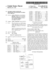
FIG. 1 (made up of FIG. 1A and FIG. 1B) is a
[0014] FIG. 2 is a schematic diagram of a Turbine Pro
cessing Unit (TPU) in accordance With the invention asso
ciated With a turbine toWer.
[0015] FIG. 3 is a schematic diagram of a meteorology
toWer associated With the system in accordance With the
invention.
[0016]
FIG. 4 is a schematic diagram illustrating the
meteorological, and substation SCADA elements. The
components and interfaces used for data collection on a
server is con?gured to receive and to store data received
meteorology toWer.
Mar. 7, 2002
US 2002/0029097 A1
[0017]
FIG. 5 is a schematic diagram of the principal
provides an interface to monitor and control the netWork and
subsystems of the system.
uninterruptible poWer supplies for the units. TACS supports
[0018]
remote netWork access. The Wind turbine processors 210
also provide remote netWork access to support on site
FIG. 6 is a schematic diagram illustrating a top
level architecture of a central server of the system.
operations access of remote systems.
[0019] Like reference symbols in the various draWings
[0026] TACS noti?es personnel of any major alarms that
indicate like elements.
may occur. A graphical user interface provides an interface
DETAILED DESCRIPTION
to alarms, alarm de?nitions and noti?cation instructions.
[0020] This speci?cation describes a system for managing
[0027] The Array Processing Unit (APU) ShoWn in FIG.
an array of Wind turbines of the kind deployed for electric
poWer generation on a commercial scale. The system is
the server.
called TACS (Turbine Array Control System).
1, the Array Processing Unit (APU) 10 is also referred to as
[0028] The APU executes application programming,
[0021] As shoWn in FIG. 1, a turbine array and TACS can
be vieWed as a Supervisory Command and Data Acquisition
Which Will be described beloW, that is responsible for
collecting data from and controlling the elements of the
(SCADA) system. The six primary entities of a Wind poWer
Wind poWer system. The APU application is built on the
system are the Array Processing Unit (APU) 10, Array
Communications NetWork (ACN) 20, Workstations 30 and
31, meteorological sites 40, poWer substation sites 50 and
client-server architecture Where the APU is referred to as the
server and the site entities are referred to as the clients.
turbine sites 60. Workstations 31 can be located in an
[0029]
operations and maintenance (O&M) site 80 remotely over a
standard Ethernet netWork. The transport medium is optical
?ber to eliminate electromagnetic and radio frequency inter
ference, ground loops and other sources of interference
Wide area netWork
and can be directly connected
directly to the netWork, as is Workstation 32. (An “array” or
“turbine array” is a group, Which may be Widely dispersed,
of Wind turbines 62 and related equipment. A “site” is a
logical grouping of all equipment and components at a
physical location.) The architecture of TACS provides high
performance monitoring and control, as Well as excellent
expansion capability With support for virtually any number
and/or type of devices.
[0022]
Site entities each contain one or more processing
elements along With the equipment being monitored and/or
controlled. Turbine sites have one or more turbine toWers
The site entities are connected to the APU over a
present in an industrial environment.
[0030] Workstations 30 and 31 execute a Microsoft Win
doWs NT application that processes the data from the APU
into various reports and alloWs real-time monitoring and
control of the Wind poWer system. The term “Workstation”
is used to refer to client computers of any kind, including
ordinary personal computers, laptop computers, personal
digital assistants, and so on. Workstations With remote
access provide a subset of the functionality of local Work
200 (FIG. 2), With each turbine toWer containing a Turbine
Processing Unit 63 (TPU) functioning as the SCADA ele
stations and are primarily used for site administration (e.g.,
softWare updates); hoWever, remote access Workstations—
Which connect to TACS through the public sWitched tele
ment for that toWer 200 or Wind turbine 63. Substation sites
phone netWork 70, for example—can be used as replace
50 and meteorological sites 40 each contain a processing
element referred to as the Substation Processing Unit 53
ments for, or in addition to, the local Workstations. Thus, an
O&M site 80 can be located remotely (FIG. 1B).
(SPU) and Meteorological Processing Unit 43 (MPU),
respectively, again functioning as the SCADA element for
the particular site.
[0023]
TACS collects and stores raW data from the sites.
The data is used for real time display and preserved in long
term storage. TACS reduces the raW data and presents it for
analysis to operations and ?nancial personnel.
[0024]
TACS provides both manual and automatic con
trols of the Wind turbines and the substation or substations
through Which energy is delivered to the electric poWer grid.
[0031]
Site-based processing elements or units execute a
client application providing local data collection and site
control. Each processing unit functions mainly as a store and
forWard device With alarm processing and local measure
ment data storage suf?cient to bridge any anticipated
unavailability of the server. Remote system administration
can be performed from any standard PC connected to the
netWork using standard WindoWs NT tools.
[0032] Monitoring Data
The turbines and substations can be controlled both manu
[0033] The APU provides database management and
ally and automatically. Automatic control can be based on
reporting functions. It collects data from all netWork com
ponents at frequent intervals, at least once a minute. It
poWer production. TACS provides a mechanism to modify
the state of the discrete outputs of the substation interface
manually With a check for reasonableness and security.
TACS provides a con?guration interface to the control
collects data (controller state, Wind speed, energy levels,
alarms, and so on) from the Wind turbine controller 220 at
a high frequency, such as once a second.
algorithm to limit energy output to the substation based on
time and poWer limits that Will automatically shut off the
appropriate number of turbines.
[0025] TACS includes a netWork 20 designed to ensure
continuous communication. The netWork is a managed Eth
ernet star con?guration. In case of a netWork failure, each
TACS subsystem is able to store its raW data locally. TACS
[0034] The APU collects and stores meteorological data
(vertical and horiZontal Wind speeds, Wind direction, tem
perature, pressure, battery level) from all toWers once every
30 seconds.
[0035]
The APU collects and stores substation data from
the SPU once a second.
Mar. 7, 2002
US 2002/0029097 A1
[0036] Processing Data
[0037] The APU also performs data processing functions.
For example, it computes and stores meteorology and poWer
production measurement data for each turbine and park.
ment data for each turbine and park, including, e.g., Wind
speed and energy levels. The GUT can display the avail
ability for every turbine and park, the alarms (active and
acknoWledged) from every turbine for up to a period of one
month, the efficiency data of each turbine and park, the state
[0038] A “park” is a grouping of turbines, Which may be
of the communication link to each turbine, the energy
logical or physical. In the particular implementation being
produced for every turbine and park, and the real and
reactive poWer for every park.
described, parks are de?ned to group physically-related
turbines. HoWever, parks can also be de?ned along other
lines, for example, to group ?nancial or oWnership interests,
contractual obligations, equipment types, and so on. With
parks of different kinds, an array of turbines can be subdi
vided into multiple sets of parks for reporting and manage
[0045] The GUT also displays the meteorological data
(vertical and horiZontal Wind speeds, Wind direction, tem
perature, pressure, battery level) from all meteorology toW
ers (FIG. 3), including the current meteorological data, last
10 minutes averages, last hour averages and the minima and
ment purposes.
maXima for the day, and the alarms (active and acknoWl
[0039] The APU computes and stores the availability for
each turbine and park; it computes and stores the alarms
edged) from the meteorological data (e.g., battery level, data
Which must be sent for noti?cation; it computes and stores
[0046] The GUT also displays the data from the substation
interface. The GUT displays the line losses, active and
reactive poWer, input poWer and output poWer for all the
circuits and totals for the current data, the last 10 minutes,
the last hour and the last day. The GUT also alloWs autho
the actual energy produced for each turbine and park; it
computes and stores the efficiencies of each turbine and
park; it computes and stores the averages for the last 10
minutes and the last hour and the minima and maXima of the
meteorological data for the day each time the data is
collected; it computes and stores the scaled units of the
substation data from substation analog inputs; and it com
putes and stores the line losses, active and reactive poWer,
input poWer and output poWer for all the circuits and totals
for the current data, the last 10 minutes, the last hour, and the
last day. The APU also alloWs an authoriZed user to display
and compare any of the collected and computed data through
a graphical user interface.
[0040]
The APU computes and stores alarms including
alarms that must be sent to notify personnel. These include
alarms from the meteorology data (e.g., battery level, data
inconsistencies, data out of range), substation interface
alarms, alarms from the server data (e.g., uninterruptible
poWer supply, operation system, database, and disk drives),
and other alarms (e.g., communications errors, data rates out
of range, out of range values and uninterruptible poWer
inconsistencies, data out of range).
riZed users to control a substation.
[0047]
The GUI provides an interface to acknoWledge and
classify alarms, to compute totals and display the alarm data,
to create and modify alarm set points of the meteorological
data, to con?gure Which data Will set alarms When out of
range or unreasonable, and to con?gure Which alarms Will be
sent to personnel for noti?cation. The APU has an alarm
noti?cation system that Will transmit alarms to the appro
priate personnel. This system can provide visual and/or
audible indication to a user from the user interface and
remotely With announcements through telephone calls,
e-mail messages, and pager messages. The GUI user Will
alWays have a vieW of any unacknoWledged alarms for all
components in the Wind poWer system. When a component
is detected With a critical event, the component name With
supplies states).
an alarm icon Will be displayed prominently in the alarm
WindoW on the front panel of the GUI. By clicking on the
alarm icon, the user is taken to the event vieW of the
[0041] System Control
component With the error.
[0042]
turbine, subject to limits of reasonableness and security,
including functions to start, stop, reset, yaW, and request
[0048] The GUI also displays the status of the uninter
ruptible poWer supply of the server and the distributed units
of the system. It supports levels of authority for data access
to the system users, and it provides a standard ODBC (Open
Database Connectivity) interface to all data in the measure
alarms. The APU alloWs an authoriZed user to con?gure the
ment database.
The APU provides a variety of tools for users to
control operation of the Wind poWer system. For eXample,
the APU provides an interface for a user to control each
control algorithm to limit energy output to the substation
based on time and poWer limits that Will automatically shut
off the appropriate number of turbines.
[0043]
The APU alloWs an authoriZed user to modify
manually the state of the discrete outputs of the substation
interface, With a check for reasonableness and security, and
to con?gure automatic controls of substation transformers.
[0044] The APU alloWs an authoriZed user to con?gure
levels of authority of system users. User Interface The APU
provides a graphical user interface (GUT) that provides
multi-level menus that alloW an authoriZed user to eXercise
command and control functions for the Wind poWer system.
The GUI updates the turbine data display at a con?gurable
Turbine Processing Unit (TPU)
[0049] As shoWn in FIG. 2, a Turbine Processing Unit
(TPU) 210 is associated With, and located close to, a turbine
toWer 200. It provides an interface betWeen the generally
proprietary turbine controller 220 provided by the turbine
manufacturer and the rest of the system. The TPU may
optionally connect to the system through a premise boX 230
providing a physical interface betWeen the optical ?ber 240
of the system netWork and the TPU 210, Which can be
connected to the premise boX With a ?ber patch cable. The
TPU 210 and the turbine controller 220 can be connected
using an optically isolated RS-232 connection.
rate With a default of once every 5 seconds. The GUT
[0050] A TPU performs the functions of data monitoring,
displays the meteorology and poWer production measure
system control, and communications at a turbine site. It
Mar. 7, 2002
US 2002/0029097 A1
[0051] A TPU interacts with the system through an Eth
ernet port and, as required, with workers who may be
slave responds with the requested data by sending a single
ASCII ‘[’ denoting the start of the data?le, followed imme
diately by a data?le type 2 structure. The speci?c data is
contained in the data?le. Upon acceptance of data, the
master transmits a single ASCII ‘]’ to the slave, terminating
working at the TPU, through optically isolated serial ports.
the communications sequence.
[0052]
[0060] A memory write (MWD) is initiated by sending a
single ASCII ‘{’ denoting the start of the data?le, followed
immediately by a data?le type 3 structure. Upon acceptance
collects data, such as controller state, wind speed, energy
levels, and alarms, from the controller at a rate of once a
second. It provides an interface to control each turbine.
TPU software runs on a Microsoft Windows NT
Embedded operating system. All software components of a
TPU operate as Windows NT services allowing them to run
at an administrator permissions level on system startup.
[0053] Wind Turbine Controller Protocol
[0054] A TPU interacts with its turbine through a turbine
controller, which is generally an off-the-shelf item provided
with the turbine by the turbine manufacturer. The TPU
implements a transport layer communication protocol for the
turbine controller, providing a uniform interface to the
system from any of a variety of turbines and controllers. The
TPU-controller protocol implementation that is described
of data, the slave transmits a single ASCII ‘]>’ to the master,
terminating the communications sequence.
[0061] A memory read (MRD) is initiated by sending the
memory read sequence, a ‘#’ followed by the two digit
turbine ID in hexadecimal notation (e.g., #01). The slave
responds with the requested data by sending a single ASCII
‘[’ denoting the start of the data?le, followed immediately by
a data?le type 4 structure. The speci?c data is contained in
the data?le. Upon acceptance of data, the master transmits a
below is for a controller made by K Electronic A/S and
single ASCII ‘]’ to the slave, terminating the communica
provided by Bonus Energy A/S, both of Denmark. The
tions sequence.
protocol is a combination of network and data transport
layers, and as such, it may be transmitted over any suitable
[0062]
physical medium.
[0055] The basic protocol follows a command-response
format, whereby each packet transmitted by the master is
acknowledged by the slave. Communication is initiated and
controlled by the master. The protocol is entirely ASCII
(text) based. Packet retransmission and cyclic redundancy
checks (CRCs) are used to minimiZe data corruption and
errors.
[0056]
ASCII character ‘?’ and wait for a retransmission.
[0063] If a data?le transmitted by the slave is not accepted
by the master, the master will respond with a single ASCII
character ‘“’ and wait for a retransmission.
[0064] Data?le Structures
[0065]
The master initiates communications with a par
ticular slave by sending the start of transmission (SOT)
sequence, a ‘SS’ followed by the two digit turbine ID in
If a data?le transmitted by the master is not
accepted by the slave, the slave will respond with a single
A data?le contains the speci?ed data and a CRC
and is terminated with an end of transmission character
(0x04). Each ?eld is separated by a single ASCII ‘/’.
hexadecimal notation (e.g., $01). The corresponding turbine
[0066] Data?le 1
responds with the ready to receive (RTR) sequence, an ‘*’
followed by its two digit turbine ID in hexadecimal notation
(e.g., *01). If the slave does not respond, or an incorrect
turbine ID is received, the master will time out. Thus, a
complete command sequences made up of the SOT
sequence, followed by a directive and a data?le of the
associated type, terminated by either a data acceptance
[0067] Adata?le 1 is used to request speci?c data from the
turbine controller and to command the controller for manual
operation. In this implementation, the type is command
request data; the direction, master to slave; the siZe, 11
characters. The commands that can be carried include the
following.
sequence or a transmission retry timeout. A data?le is the
payload of a message. Data?le types are described below.
Command sequences may be initiated inde?nitely.
[0057] The master can send four directives representing
command request, data request, memory write or memory
read. Directives are sent immediately following a valid SOT
sequence. Data acceptance is signaled by transmission of the
“closing character” matching the “opening character” sent
for the speci?c directive. Upon receipt of this character the
communications sequence is terminated.
[0058] A command (CRD) request is initiated by sending
a single ASCII ‘(’ denoting the start of the data?le, followed
immediately by a data?le type 1 structure. The speci?c
command is contained in the data?le. Upon acceptance of
data, the slave transmits a single ASCII ‘)’ to the master,
terminating the communications sequence.
Char
C
B
>ozwer
Description
Computer reset
Brake turbine
Yaw CW (clockwise)
Yaw CCW (counterclockwise)
Do not care
Start automatic operation
Motor start turbine
Quit fault code (acknowledge)
Move alarm stack pointer to newest
[0068] Data?le 2
[0069] A data?le 2 contains data returned from the con
troller. The ?elds all have a ?xed length and the message
[0059] A data request (DRD) is initiated by sending the
contains all ?elds regardless of content. In this implemen
tation, the type is command response data; the direction,
data request sequence, namely, an ‘&’ followed by the two
slave to master; the siZe, 208 characters. The data ?elds of
digit turbine ID in hexadecimal notation (e.g., &01). The
a data?le 2 function are shown in the following tables 1-6.
Mar. 7, 2002
US 2002/0029097 A1
TABLE 1
TABLE 2-c0ntinued
Field De?nitions
Turbine Status Codes
Field Name
Range
Units
Description
Year
Month
00-99
01-12
Years
Months
Wind enough for automatic start and motor start
No operation, Wind too Weak
Day
01-31
Days
Hours
00-12
Hrs.
Minutes
Turbine status
00-59
see Table 2
Min.
Brake status
see Table 3
[0071]
Generator status
see Table 4
YaW timer
—32765 —+ 32765 (‘/10 sec.)
TABLE 3
Power
0000.0—9999.9
kW
Reactive poWer
—999.9—|-999.9
KVar
PoWer factor
—9.99—+9.99
Sec.
‘J = CCW, "l" = CW
Brake Status
Code
Description
Brake Pulled
Wind speed
00.0-99.9
m/s
B
Grid frequency
OO_O_99_9
HZ
b
Not su?icient pressure yet
Generator RPM
0000-9999
RPM
=
Brake released
Rotor RPM
Generator 1 temp.
00—99
—99-150
RPM
° C.
Generator 2 temp.
—99-150
° C.
GearboX temp.
Ambient temp.
—99-150
—99-150
° C.
° C.
Phase R voltage
000-999
v
Phase S voltage
Phase T voltage
000-999
000-999
V
v
Phase R current
000-999
A
Phase S current
000-999
A
Phase T current
000-999
A
G
Large generator Cut in
Energy subtotal gen. 1
000000000-999999999
KWh
I
Large generator Cutting in
Small generator Cut in
[0072]
TABLE 4
w
Code
Description
Prod. time subtotal gen. 1
000000-999999
Hrs.
g
Energy subtotal gen. 2
000000000-999999999
KWh
i
Small generator cutting in
Prod. time subtotal gen. 2
000000-999999
Hrs.
m
Motor start on generator
Energy total gen. 1
Prod. time total gen. 1
000000000-999999999
000000-999999
KWh
Hrs.
t
*
Motor start not alloWed in 7.5 min.
Generator is inactive
Energy total gen. 2
000000000-999999999
KWh
Prod. time total gen. 2
000000-999999
Hrs.
Safety sWitch
0 = remote, 1 = local
Operation code
see Table 6
Error code
see Table 5
Last error year
00-99
Years
Last error month
01-12
Months
last error day
01-31
Days
last error hour
00-23
Hrs.
[0073]
TABLE 5
M
last error minute
00-59
Min.
Code
last error seconds
00-59
Sec.
00
System Faultless
01
02
03
04
24 volt control voltage cut off
Uncontrolled yaWing 24 volt cut off
SoftWare Watchdog error
I
Cut out error on large generator, free Wheeling
TABLE 2
05
06
Brake time exceeded, free Wheeling
Large generator time cut out
07
Error temperature measurement
Turbine Status Codes
O8
Anemometef error
Code Description
09
10
Ambient temperature less than —20 degrees
YaW motor superheated
11
YaW contactor or thermal error
F
Fault condition
12
Cable tWist sensor activation error
S
W
Out of Work, must be started manually
Too strong Wind to operate
13
14
Continuous yaW limit eXceeded
Frequency error on mains
W
R
L
r
1
Too strong
Cables are
Cables are
Cables are
Cables are
15
16
17
18
19
Asymmetry in current
Voltage error on mains
Vibration sensor activated
Oil level in gearboX too lOW
Pressure in brake system too lOW
s
Stopped for tWisting, Waiting for less Wind speed
20
Hydraulic pump error
M
Manual motor start in progress
21
Worn or overloaded brake blocks
A
O
P
t
Automatic motor start in progress
Not yaWed up in the Wind yet
Start at Wind limit for bypass small generator
Control time for Wind speed before start
22
23
24
25
Thermally cut out large generator
Large generator RPM sensor error
Generator contactor error
By pass contactor error
[0070]
Wind to start
tWisted automatically
tWisted automatically
tWisted automatically
tWisted automatically
clockWise (CW), sensor
counter-clockwise (CCW), sensor
CW, yaW timer
CCW, yaW timer
Description
Mar. 7, 2002
US 2002/0029097 A1
vertical wind speed, temperature, and pressure. The data is
Code
TABLE S-continued
logged through a Campbell CR10X data logger 320, avail
able from Campbell Scienti?c, Inc. of Logan, Utah. The data
Error Codes
logger has a remote RS-232 serial communication interface
through which sensor values in engineering units can be
Description
26
requested.
RPM on rotor has exceeded maX limit
27
Main bearings superheated
[0081]
28
Main shaft RPM sensor error
thus multiple loggers associated with each park.
29
Motor start not succeeded 5 times
30
Large generator superheated
31
Oil in gearbox superheated
32
33
Thyristors superheated
Overproduction in large generator
34
35
Current asymmetry in small generator
Small generator thermally cut out
36
Belt error or RPM sensor error, small generator
37
Motor start RPM limit eXceeded
38
Small generator superheated
39
Sequential error
40
Error during performance of averaging
There will generally be multiple met masts and
[0082] Meteorology Tower Components and Interfaces
[0083]
FIG. 4 illustrates the components and interfaces
used for data collection on a met mast. The temperature
sensor 318 is a Campbell 107 sensor. The pressure sensor
330 is a Vaisala PTB101B sensor. The vertical wind speed
sensor 311 is a RM Young 27160T sensor. The horizontal
wind direction sensors 310, 313, 315, 317 are NRG Type
200P sensors. The horizontal wind speed sensors 312, 314,
316, 319 are NRG Type 40 sensors. The met mast equipment
also includes battery backup and charging components 340
and a ?ber optic (FO) modem 350.
[0074]
[0084] Met Mast Logging
TABLE 6
Operation Codes
[0085] All met mast data is time stamped with Julian day,
year, hour, minute, and second.
Description
[0086] The APU collects the following data for a met mast
data screen of the TACS GUI in real time from the MPU:
00
01
Normal operation
Operational stop with automatic start
battery level, temperature, atmospheric pressure, four hori
02
Motor start cut out due to fault
03
Small generator cut out due to fault
These measurements are made available to the GUI through
O4
05
06
Stopped for manual start
Stopped has to be restarted
Free wheeling has to be restarted by reset
the database.
Code
[0075] Data?le 3
zontal wind speeds, and four horizontal wind directions.
[0087] The APU also processes the raw data into the
following summary data for a summary met mast data
screen. These processed values are made available to the
GUI through the database.
[0076] A data?le 3 is used for setting the onboard clock,
averaging times for data collection, and adjusting limits and
control values. If the contents of the data ?eld is ‘XXXXX’,
the memory location will not be written, but the address is
selected for reading on the following memory read directive.
This function performs word writes only. In this implemen
tation, the type is memory write data; the direction, master
to slave; the size, 20 characters.
[0077] Data?le 4
[0078]
A data?le 4 reads data from the selected memory
location. The function is used to view data not available in
the standard data?le 2 payload. In this implementation, the
type is memory read data; the direction, slave to master; the
size, 20 characters.
Daily Daily
Data Item
MaX
Daily
Daily
10
10 Minute
Standard
Minute
Standard
Min Average Deviation Average Deviation
Battery level
X
X
X
X
temperature
X
atmospheric
X
X
X
X
X
X
X
pressure
vertical wind
X
X
X
X
X
X
X
X
speed
horizontal wind
speed
wind direction
X
X
Substation Processing Unit (SPU)
Meteorological Processing Unit (MPU)
[0088] A Substation Processing Unit (SPU) is the on-site
[0079] As illustrated in FIG. 3, a Meteorological Process
4) is the interface between the wind turbine power plant and
the electrical grid. The SPU is implemented using a pro
interface of the system to a substation. Asubstation 52 (FIG.
ing Unit 43 (MPU) provides meteorological data from
sensors 310-319 on and at a meteorology tower through a
grammable logic controller (PLC) 54 that manages the
data logger. The MPU collects and stores meteorology tower
data, such as vertical and horizontal wind speeds, wind
substation interface.
direction, temperature, pressure, and battery level, from all
[0089]
The PLC is an Allen-Bradley SLC 500 processor
the towers regularly, such as once every 30 seconds.
based controller. The SLC 5/05 processor provides high
bandwidth networking. As shown in FIG. 5, the PLC 510 is
[0080] As illustrated in FIG. 3, in one design, a meteo
rology tower (also referred to as a “met mast”) 42 monitors
connected to the Server 10 over an Ethernet link using
RSLinX as an interface driver and is programmed with the
wind speed and direction from 4 levels above the ground,
RSLogiX tool. RSLogiX 500 provides consolidated project
Mar. 7, 2002
US 2002/0029097 A1
vieW and drag-and-drop editing. (As shown in FIG. 1B, the
[0099] The Legacy Controller Interface (LCIF) controller
server and the substation controller can be collocated at a
protocol provides a generic turbine interface de?nition in
substation site.) The modules for discrete inputs are sinking
order to support the future installations of TACS in sites
DC input modules, product number 1746-IB32; the analog
I/O modules, product number 1746-NI8, and the digital
output modules, product number 1746-OX8.
[0090] The IB-32 Module provides 32 digital sinking
Where different turbine controllers are used.
inputs, used With 24 VDC. It is organiZed into four groups,
each With eight digital inputs and tWo commons. All com
interface (MMIF).
mons are connected to the common measurement ground
connection point. A +24 VDC signal present at the input
[0101] The Substation Interface (SSIF) connects the
Allen-Bradley Programmable Logic Controller (PLC) in a
indicates the input is in the active state.
substation to the server. The SSIF communicates With the
[0091] The OX-8 Module provides eight fully isolated
[0100] The Campbell CRlOX Logger supports a Campbell
proprietary serial communication interface. This is recog
niZed by the MM listener and used as a meteorological mast
PLC using the Allen-Bradley RSLinX communication pro
tocol over the Ethernet netWork.
relay contact pairs, Which can be used for digital output
connection.
[0092] The NI-8 Module provides eight differential analog
inputs Which can be connected for differential or single
ended measurement. As con?gured in this system they are
connected in a differential arrangement With the positive and
negative input terminals connected to the respective positive
and negative outputs of the sensors. Shielded cable is used
for analog connections to minimiZed noise and ensure the
greatest measurement accuracy.
[0093]
The PLC program monitors the substation trans
former and keeps the output Within limits by controlling the
transformer step adjustment.
[0094]
The PLC program announces errors though
memory tags containing the state of the alarm condition.
control and communicate With all of the TACS subsystems.
[0103]
To support the noti?cation of alarms to users of
TACS, a short message service interface (SMSIF) provides
an interface to a Wireless Short Message Service to deliver
pager or email messages.
The APU (Continued)
[0104]
FIG. 6 shoWs the top-level architecture of the
APU. The APU is implemented on a conventional computer
server platform, such as a DellTM PoWerEdge 2300 com
puter. The server runs Microsoft WindoWs NT Server 4.0
With Service Pack 5 or later. Online disk memory is advan
tageously a RAID (Redundant Array of Inexpensive/Inde
pendent Disks) con?guration With about 40 gigabytes of
The Array Communications NetWork (ACN)
[0095]
[0102] Any remote subsystems can be connected through
a generic remote equipment interface (RECIF) protocol to
The ACN 20 is the netWork component of the
system. The netWork is a local area netWork based on
storage, estimating about 10 gigabytes to store the raW data
for one month of operation.
Ethernet technology. The interconnections are generally
[0105] The folloWing paragraphs describe the softWare
based on optical ?bers. The ACN is used to collect data from
all netWork components, generally at the rate of at least once
a minute. The ACN also provides a mechanism to con?gure,
operate, and maintain the netWork components and to dis
architecture of the APU. Data Storage Agent The Data
Storage Agent 610 is the encapsulation of the data storage
play con?guration and operational status (such as commu
nication errors and data rates) of all the netWork compo
nents.
All
control
and
monitoring
equipment
is
interconnected by the netWork. In case of a netWork failure,
each subsystem is eXpected to store its raW data locally for
up to 48 hours.
Interface De?nitions
and data interface for TACS. The DBIF provides the TACS
applications an Application Program Interface to access,
store and update data in the databases.
[0106] The TACS database is implemented using
Microsoft SQL (Structured Query Language) Server Version
7.0. The database supports remote communication through
ODBC to the subsystems. The TACS database includes a
con?guration, an events, and a repository database, Which
Will be described.
face that the TACS components use to communicate With the
[0107] The current month’s and last month’s data are
maintained online. At the end of each month, all of last
month’s data is archived and the current month’s data
becomes last month’s data. Annual accumulated totals of
production and other data are maintained and available
database. This interface consists of three parts: database
throughout the year.
[0096]
FIG. 5 is a block diagram of the principal sub
systems and shoWs the names of the interfaces used.
[0097]
The Database Interface (DBIF) is a standard inter
language statements, function interface, and netWork proto
col. The database language statements and function interface
are encapsulated Within a database application programming
interface
The TACS database provides native data
base API support for Microsoft OLE DB and ODBC.
[0108] A Data Mapper class is provided to alloW a com
mon interface betWeen TACS applications and the TACS
database. The class provides a connection service and an add
service to put data into the TACS repository database.
[0098]
tiprotocol. The Multiprotocol Net-Library uses the WindoWs
[0109] Microsoft SQL Server 7.0 utilities are used to
manage the database. Generally, the databases are de?ned
and instantiated upon installation of the system. The SQL
Server incorporates services to manage the databases auto
remote procedure call (RPC) facility.
matically and manually.
The TACS database alloWs client connection using
three netWork protocols: named pipes, TCP/IP (Transmis
sion Control Protocol/Internet Protocol) sockets, and mul
Mar. 7, 2002
US 2002/0029097 A1
[0110] Data Display Agent
[0111] The Data Display Agent 620 supports interaction
with TACS through the GUI, which can be accessed locally
or remotely. Local access can be through a direct connection
to the ACN or to an element of the system. Remote access
640 can be over a WAN (wide area network), including over
the Internet, or through a telephonic connection, such as
through a wireless link or a public switched telephone link.
The user interface is organiZed in a tree structure and
supports the drill down to any speci?c information the user
may wish to view. The user interface supports multiple
views to each subsystem to allow users access to real time
[0120] When an evaluation group is processed, the DPA
queries the database for all DPA rules belonging to the
group. Then, the evaluation procedure for each DPA rule
belonging to the group is executed. If the DPA rule evalu
ation returns a result set (the result of a SELECT statement
in the stored procedure), the DPA checks whether the rule
has an action procedure to execute. If so, the DPA executes
the speci?ed action procedure with Zero or more parameter
values from the corresponding evaluation result set. This
allows ?eld values from the result set to be passed to the
action procedure.
[0121]
Each DPA rule contains the con?gurable ?elds
data, summary data, alarms data, and subsystem controls.
described in the table below. If the con?guration for a
parameter is NULL, then the DPA will not include that
[0112] The tree structure is displayed to give the user easy
access to the components in the system. By double clicking
on the icon representing a component in the tree, the window
for the component is displayed in the main GUI window.
The icons displayed in the tree display show the state of the
parameter when executing the action stored procedure.
FIELD
DESCRIPTION
related components, such as turbines and met masts. Each of
the elements in the tree structure provides an interface to the
window into the element. Each window contains a number
Evaluationiproci
The name of the evaluation stored procedure
of tabs to provide different views into the element.
[0113]
The following tabs are typically available in the
name
hasiaction
Set true if this DPA rule has an action to process.
actioniprociname
actioniparamil
GUI window. Each can be selected to display a correspond
ing view, as described below.
actionfparamfZ
actioniparamil’s
Tab Name
Description of View
Tabular
Graphical
Summary
Raw data presented in tabular format
A strip chart of raw data and bar chart of reduced data
Data reduced from raw data for real time data analysis
Control
Events
Control interface to the element
List of all the unacknowledged events from the element
Instrumented
Raw data presented in graphical format
[0114] The GUI can provide a graphical view of the whole
array, or of any park individually. This interface can provide
Otherwise, set false.
The name of the action stored procedure
If not NULL and hasiaction is true, this string is
passed as the ?rst parameter when the actioni
prociname stored procedure is called.
If not NULL and hasiaction is true, this string is
passed as the second parameter when the actioni
prociname stored procedure is called.
If not NULL and hasiaction is true, this string is
passed as the third parameter when the actioni
actioniparami4i
prociname stored procedure is called.
If not NULL and hasiaction is true, this string is
?eldkey
used to look up a value in the result set which will
be passed as the fourth parameter when the actioni
prociname stored procedure is called.
actionfparamfSi
special
If both ?elds are not NULL and hasiaction is true
then these ?elds create the ?fth parameter to be
actionfparamfSi
?eldkey
passed when the actioniprociname stored
procedure is called.
actioniparami6i
special
If both ?elds are not NULL and hasiaction is true
then these ?elds create the sixth parameter to be
actioniparami6i
?eldkey
passed when the actioniprociname stored
procedure is called.
an overview of the whole array at a glance.
[0115] Data Processing Agent (DPA)
[0116] The Data Processing Agent (DPA) 630 is imple
[0122] The evaluation stored procedure may contain any
valid combination of SQL commands, although if multiple
mented as a generic NT service that periodically makes one
or more decisions by evaluating data in the database.
data set.
[0117]
The con?guration details for each DPA decision are
saved as a DPA rule in the con?guration database. Each DPA
rule has an enable ?ag, description, evaluation group, evalu
ation procedure (stored procedure) name, and optional
action ?elds. If the enable ?ag for a particular DPA rule is
Zero, then that DPA rule is not evaluated during processing.
If the enable ?ag is set to ‘1’, then it is enabled for
evaluation.
result sets are returned, the DPA will only review the ?rst
[0123] The action stored procedure may contain any valid
combination of SQL commands.
[0124] The DPA has two methods of reporting error con
ditions. Problems executing an evaluation procedure or
action procedure are saved as an event record in the events
database. InitialiZation or operational problems with the
DPA service are stored in the NT event log.
[0125]
The DPA is used to implement the following three
main functional components of TACS: automatic power
[0118] Each DPA rule also belongs to a class. The class
distinction allows the DPA additional execution ?exibility in
the implementation of the processing engine.
control, post processing, and event processing.
[0126] Autopilot Agent
[0127]
[0119] The DPA wakes up once a second and queries the
database for evaluation groups. Each evaluation group has
an evaluation period that is compared against the current
system time to determine whether the group should be
processed at the current time.
It is at times necessary to limit the power output of
the wind power system; for example, the utility company
may need to work on power lines. The Autopilot Agent 650
is noti?ed when it is necessary to increase or decrease a line
power level. The Autopilot Agent monitors the power level
and queues a turbine control command when necessary. The
Mar. 7, 2002
US 2002/0029097 A1
Autopilot Agent determines Which turbine should be turned
off to decrease the power level or Which turbine to turn on
to increase the poWer level.
[0128] An authorized user can enter Autopilot rules
through the GUI. For example, a user can enter the Autopilot
[0133] Post Processing Agent
[0134] The Post Processing Agent periodically processes
the raW data collected from system components and stores
the reduced data in the summary data tables for the GUI
time range, poWer limits, and a short description through the
summary screens. This agent also implements other periodic
system functionality such as subsystem communication fail
GUI. When an operator deletes an existing automatic control
record, the GUI Will execute a stored procedure to delete the
ure detection and event creation.
record. This stored procedure is in the con?guration data
[0135]
base.
parameters are con?gured to implement the post processing
data reduction agent.
The table beloW describes hoW the DPA rule action
[0129] When the operator adds a neW automatic control
record or edits an existing record, a pop-up dialog box is
displayed. Pressing the OK button Will cause the GUI to
execute a stored procedure to add or edit the record. These
FIELD
stored procedures are in the con?guration database.
Evaluationiprociname
[0130]
DESCRIPTION
Contains the name of the stored procedure that
Will perform the desired data processing. The
stored procedure should be located in the
The table beloW describes hoW the DPA rule action
parameters are con?gured to implement the Autopilot Agent.
FIELD
Evaluationiprociname
DESCRIPTION
dpairuleiautopilotievaluation — The name of the stored
procedure to evaluate all autopilot records.
hasiaction
actioniprociname
1 — Which indicates it has an action to process.
dpaiactioniautopiloticontrol — The name of the stored
procedure to perform the autopilot action for all autopilot
actioniparamil
actionfparamfZ
actioniparamil’s
actioniparami4i?eldkey
records.
Minimum poWer limit in Watts
Maximum poWer limit in Watts
Time range, start time in UTC seconds
mainiactiveipower — This column value is read from the
result set and passed as the fourth parameter to the action
procedure. Since the evaluation procedure selects from
the substationilatest table, this Will get the latest real
actionfparamfSfspecial
poWer value and pass it to the action procedure.
Time range, end time in UTC seconds
actionfparamfSf?eldkey NULL
actioniparami6ispecial NULL
actioniparami6i?eldkey
timeistamp — returns the current UTC time to the action
procedure.
[0131] The stored procedure dpa_rule_autopilot_evalua
tion determines, at regular intervals such as every 30 sec
onds Whether there is an autopilot record to process. If there
is and if
the current time is Within the time range
speci?cation and the total poWer is outside the maximum or
-continued
FIELD
DESCRIPTION
repository database. The name should folloW
minimum poWer limits, then the dpa_action_autopilot_con
trol stored procedure is performed. This procedure ?nds a
turbine to shut doWn if total poWer exceeds the maximum or
?nds a turbine to turn on if total poWer is less than the
minimum. Such a turbine must be under auto control. If such
a turbine is found, a command to the turbine is enqueued and
an information event is created. If no such turbine is found
to turn off, a critical event is created.
[0132] Additional functionality for the Autopilot Agent is
encapsulated in the stored procedure dpa rule_autopilot
the convention ‘dpairuleinnnnnixxu’
Where ‘nnnnn’ is the associated DPA rule
key identi?er and ‘xx..’ describes the
effect of this post processing operation.
hasiaction
0 — Which indicates it has no action
All remaining ?elds ——
NULL
[0136] The speci?c functionality for each data reduction is
encapsulated in the corresponding evaluation stored proce
maintenance, Which is periodically executed. This procedure
dure for that DPA rule. Note that the action ?elds are not
looks for autopilot control commands that have timed out
used for the data reduction agent.
and creates an event. It also looks for turbines that have been
manually controlled by an operator and removes these
[0137]
turbines from control by the autopilot.
procedures used by the data reduction agent.
The table beloW describes the evaluation stored
Mar. 7, 2002
US 2002/0029097 A1
10
DPA Rule Evaluation Procedure Name
Description
1000
dpairuleiturbineicmdicleaner
Detects stale turbine control commands
1010
dpairuleiautopilotimaintenance
Detects problems With automatic
1020
dpairuleitpuicommandibridge
Handles processing of operator manual
1030
dpairulei01030isubicommifail
1040
dpairulei01040imeticommifail
control of turbines
control commands from the GUI
1090
10001
10002
dpairuleipostitime
Detects communication failure With
the substation data collection
Detects communication failure With
the meteorological mast data collection
Posts the current time for SQL access
dpairulei1000liturbineisummary
dpairuleil0002imetsienvitabular
10003
Creates summary data for turbines
Creates environmental summary data
over all meteorological sites
dpairulei10003imetsiwinditabular Creates Wind summary data over all
10004
dpairulei10004imetsisummary
meteorological sites
Creates summary data for all
meteorological sites
10005
dpairulei10005ioneimetisummary Creates summary data for each
10010
dpairulei10010fturbinefcomm
10020
dpairuleil0020ispainisummary
10100
10101
dpairulei10100iparkisummary
dpairulei1010liparkitabular
meteorological site
11000
dpairulei11000i10MINidata
12000
dpairuleil2000fturbinefavailability
Detects communication failure With
the turbine data collection
Creates summary data for all parks in
an aggregation called Spain
Creates summary data for the parks
Creates summary data for the parks
tabular WindoW in the GUI
Creates summary data for 10 minute
values
Creates summary data of turbine
availability
[0138] Event Noti?cation Agent
[0139] The Event Noti?cation Agent is responsible for
notifying operators of TACS events. Events may be infor
mational, Warning, or critical. Critical events are alarm
criteria include speci?cation of comparison operands, com
parison operator, evaluation group, event description, and
alerting information. The GUI adds, edits, or deletes event
con?guration records by executing the respective stored
conditions in the system. This agent detects the speci?c
procedure sp_dpa_add_event_record, sp_edit_event_record,
event condition, adds an event record in the log, and noti?es
operators of the event.
or sp_delete_event_record in the con?guration database.
[0140] A TACS system administrator can con?gure event
criteria using the TACS con?guration console. The event
eters are con?gured in the DPA rules to implement the event
[0141]
The table beloW describes hoW the action param
processing agent.
Field
Description
evaluationiprociname
Contains the name of the stored procedure for this event
noti?cation. The stored procedure is in the repository
database. The name folloWs the convention
‘dpairulei20nnnieventidetection’, Where ‘nnn’ is the
associated DPA rule key identi?er (betWeen 20000 and
20999.
has faction
1 — Which indicates it has an action to process
actioniprociname
Contains the name of the stored procedure that Will be
eXecuted if this event is detected. For the con?gurable
events the stored procedure is
actioniparamil
The DPA rule number; used as the event identi?er number
actioniparami2
The event level for the event log: 1 = informational,
actioniparami3
The event source category for the event log: 2 = TPU,
actioniparami4i?eldkey
The column name (corresponding to the evaluation
procedure SELECT table) to return the event source number
‘ dpaiactioni20000ieventinotify ’.
in the event log
2 = Warning, 3 = critical
3 = meteorological site, 4 = Substation
for the event Jog.
Mar. 7, 2002
US 2002/0029097 A1
-continued
Field
Description
actionfparamfSfspecial
A short description of the event for alerting
actionfparamfSf?eldkey
actioniparami6ispecial
?eld name — The column name of a ?eld value to include in
the event description
The alerting string: If NULL then alerting is disabled. If
eXists then it is included in the alerting record. This string
contains the alerting group information
actioniparami6i?eldkey NULL
[0142] System Health Monitor
[0143] The System Health Monitor 660 is responsible for
collecting and evaluating events that are related to the status
of the system health and reporting the results to the events
database. The System Health Monitor also checks the sub
systems and reports when there is a failure to respond.
[0144] Remote Access
[0145]
The APU provides remote access 640 for the TPUs
and the GUI. The TPU Control Agent 520 (FIG. 5) receives
messages that are sent to the TPU through the RECIF
interface. Control messages are sent from the Autopilot
thread of the DPA 630 and from the user through the GUI.
[0146] Substation Processing Unit Control
[0152] If communication with the met mast is lost and the
raw data is not available for sampling, the logger will
continue to collect the raw data and reduce the values into
the data required for any mandatory data reductions. The
reduced data can be accessed from the logger locally or
through the network when communication is restored. The
data can be retrieved with the Campbell Scienti?c PC208W
tool.
[0153] The MMListener is implemented as an NT Service
dependent on the SQL Server Service. The service reads the
TACS SQL con?guration database and determines if there
are any meteorological towers. Aworker thread is started for
each of the met masts. The worker threads are set up to run
once a second. On startup, the treads open a connection to
the database and the communication port for the met mast.
[0147] The Substation Processing Unit (SPU) Control 670
Then, synchronized communication with the logger is estab
process continually monitors the substation for discrete and
analog inputs. The SPU Control also manages the discrete
outputs set through the GUI or otherwise.
lished. Any failure creates an alarm condition.
[0148] The SPU Control is implemented using the Rock
well Software’s RSSql and RSLinX software packages.
RSSql is responsible for interfacing with the Allen-Bradley
PLC (which manages the substation interface) through
RSLinX. This process collects data samples from the sub
station and stores them in the substation data tables of the
TACS database. The PLC program converts all of the analog
inputs to the correct engineering units before storing them in
the memory tag to be read by the server.
[0149]
RSSql also monitors the database for requests to
pulse substation discrete control outputs. When a record is
inserted into the substation control table, RSSql reads the
output command then sets the PLC output command sym
bol. After the command has been sent to the PLC the
command record is removed from the database. The PLC
reads the command output in the output command symbol
then holds the corresponding discrete output line closed as
required. Then the PLC clears the output command symbol
value.
[0150]
[0151]
[0154] The worker thread is responsible for requesting the
raw input sensor data from the logger. The data is sampled
in two sets because there is a different update rate for each
of the sets of data. The ?rst set of data is the wind data. This
data is collected once a second from the 8 horizontal wind
sensors and the 1 vertical wind sensor. The second set of data
is the environment data. This data is collected once every 30
seconds from the atmospheric pressure, temperature and
battery level sensors.
Database Schema
[0155] The TACS database 530 (FIG. 5) includes a con
?guration database, an events database, and a repository
database.
[0156] The con?guration database contains the data asso
ciated with the current con?guration of the system. This
includes names and identities of all the TPUs, met masts,
and substations in the system. The current Data Processing
Rules and Alarm Con?guration are also stored here.
[0157] The events database contains records of the events
that have occurred in the system. Some of the events are
Met Mast Listener
alarms; some, simply informational. The tables include
The Met Mast Listener process (MMListener) 680
occurrence time and message, acknowledgement time and
message, and closure time and message.
collects the raw data from the met mast data loggers. Once
the data is collected from a logger, the Met Mast Listener
uses the TACS Data Mapper interface to connect to the
TACS databases and store the data in the TACS repository
database.
[0158] The repository database contains all of the raw data
samples collected from the TPUs, met masts and substa
tions. This raw data is available for post processing and data
analysis. To save data storage space, data that can be reduced
Mar. 7, 2002
US 2002/0029097 A1
12
from the raw data is only updated in tables to make the data
available to the GUI. Some of the raw data is also stored in
updated tables with the same data so that the GUI can access
data tables with very few records.
Repository Database
[0159] TABLE turbine_latest
[0160] A record is updated in the turbine_latest database
table each second by each TPU. The source of the data is the
TPU, eXcept as noted. This table contains the latest value of
the turbine data samples. The data in this table is used in the
GUI turbine window tabular view.
Field
Description
turbineinumber
TPU database identi?er number
timeistamp
Time Stamp. Here and elsewhere, time is in seconds
[0161] TABLE turbine_history
[0162] A record is added to the turbine_history database
table each second by each TPU. This table contains a history
of the turbine data samples. The ?elds of this table are
identi?ed by a check mark in the description of the turbine_
latest database table, above.
[0163] TABLE turbine_summary
[0164]
(unless stated otherwise) by the DPA. The data in this table
is used in the GUI turbine window summary view.
History
since midnight, January 1, 1970, coordinated
universal time (UTC) or Greenwich mean time
(GMT).
operationalistatus
Operational State. A code for one of: running OK;
fault; no communication (set by DPA if
turbineistatus
Turbine Status. A code for one of: fault; off; too
communication fails); offline; available; not ready.
much wind; cables twisted (left or right); manually
starting; automatically starting; not yawed; start at
wind limit; control time before start; enough wind;
brakeistatus
too little wind
Brake Status. A code for one of: brake pulled; not
generatoristatus
Generator Status. A code for one of: large generator
enough pressure; brake released.
cutting in; small generator cutting in; motor start on
generator; no motor start for 7.5 minutes; generator
inactive.
generatorirpm
Generator RPM
generatorilitemp
generatori2itemp
gearboxitemp
ambientitemp
Generator 1 Temperature
Generator 2 Temperature
windisp eed
gridifreq
roto rirp m
Yaw
windidirection
realipower
Gearbox Temperature
Ambient Temperature
Wind Speed
Grid Frequency
Rotor RPM
Yaw
Wind Direction. Calculated from turbine yaw value
in database
Real Power
reactiveip ower
Reactive Power (KVar)
powerifactor
phaseirivoltage
phaseisivoltage
phaseitivoltage
phaseiricurrent
phaseisicurrent
phaseiticurrent
genilienergyittl
geni2ienergyittl
geniliproditimeittl
geni2iproditimeitt1
safetyiswitch
operationicode
Power Factor
Phase R Voltage
Phase S Voltage
Phase T Voltage
Phase R Current
Phase S Current
Phase T Current
Generator 1 Energy Total (KWh)
Generator 2 Energy Total (KWh)
Generator 1 Production Time Total (Hours)
Generator 2 Production Time Total (Hours)
Safety Switch: remote or local.
Turbine Operational Code. A code for one of:
normal operation; operational stop with automatic
start; motor start cut out due to fault; small generator
cut out due to fault; stopped for manual start; stopped
— must be restarted; free wheeling — must be restarted
by reset.
This database table contains one record for each
TPU. All records in this table are updated once a second
\
Mar. 7, 2002
US 2002/0029097 A1
13
Field
turbineinumber
Description
(a blank description means that a previously-given description
applies.)
timeistamp
operationalistatus
Operational State, from turbineilatest table
av gip ro diparker
Average Production over 10 minutes
Here and elseWhere,
production is calculated according to the measurement algorithm
from IEC 61400—12:1998(E) Wind turbine generator systems —
Part 12: Wind turbine poWer performance testing (“Parker”).
expectediprodiparker
productionie?iciency
Expected Production over 10 minutes
availabilityiperihour
Availability per Hour. This value is calculated once a minute (as
Production E?iciency. This is 100% times avgiprodiparker
divided by expectediprodiparker
a percent) using the previous 3600 samples of the
operationalistatus.
numberiofialarms
Number of active unacknowledged alarm records for this turbine
[0165] TABLE turbine_control_requests
[0169] TABLE turbine_autocontrol
[0166] This database table contains the queue for TPU
control requests from the GUI. A request record can be
inserted into the database table by the GUI or other system
[0170] This database table contains one record for each
turbine in the system. Turbines that are alloWed to be
device. The DPA examines this database table once a second
to process Waiting command requests. When the DPA reads
the record, it also deletes the record.
Field
turbineinumber
transactioninumber
automatically controlled by autopilot Will have their auto
pilot enabled ?eld set by the GUI. If an operator manually
controls a turbine through the GUI, the turbine is removed
from automatic control.
Source Description
GUI
SQL
TPU database identi?er number
Request Transaction Number. A transaction number is
added by the SQL server When a record is inserted in
the substationicontroliqueue.
commandistr
GUI
Command String. A code representing one of: manual
start request; manual stop request; manual reset
request.
[0167] TABLE turbine_control
[0168] This database table contains the queue for TPU
control requests. A request record may be inserted into this
table by the DPA in response to a request record being
inserted in the turbine_control_requests table. Each TPU
examines this table once a second to see if a control record
is Waiting. When the TPU reads the record from the table it
also deletes the record indicating that the control request has
been received.
Field
Source
Description
TPU database identi?er number
turbineinumber
autopilotienabled DPA, GUI Autopilot Enabled Status
autopilotishutdoWn DPA
Autopilot State
shutdoWnicount
DPA
Number of times this turbine has been
shut off by autopilot. Incremented
each time turbine is automatically shut
off by autopilot. This counter is
used by autopilot algorithm to
Field
determine Which turbine to shut off.
Source Description
turbineinumber
DPA
transactioninumber
commandistr
SQL Request Transaction Number, as above
DPA Command String, either 1=start or 2=stop
TPU database identi?er number
[0171] TABLE turbine_comm_latest
timeistamp
DPA
Time command Was inserted into this
[0172]
queue
turbine in the system. The source is the DPA. The comm
This database table contains one record for each
_failure ?eld speci?es the latest communication status for
the respective turbine.