1
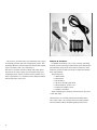
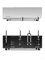
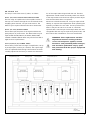
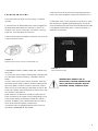
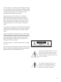
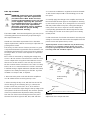
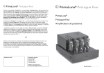
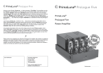
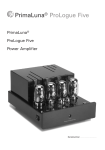
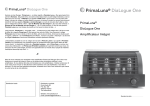
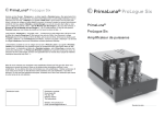
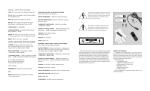
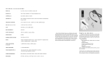
ANTHEM AMP 1
OPERATI NG M AN UA L
CONTENTS
page
Parts List ..................................................................................................................1
Front & Rear Panels ................................................................................................2
Control Functions ....................................................................................................3
Connection Functions..............................................................................................3
Setting Up................................................................................................................4
Tube Insertion..........................................................................................................5
Operation ................................................................................................................5
Troubleshooting ......................................................................................................6
Safety Instructions....................................................................................................7
Disclaimer of Liability................................................................................................7
Warranty ..................................................................................................................7
Bias Adjustments ....................................................................................................9
Technical Specifications..........................................................................................10
9/96 SKU# 56848
We at Sonic Frontiers hope you will derive many years
of listening pleasure with your new Anthem Amp 1. This
Operating Manual contains important information regarding the operation and care of the Amp 1.
Be sure to read this manual carefully and follow these
instructions in order to keep your unit performing and
sounding its best. Please contact Sonic Frontiers if you
have any questions, a Customer Service Representative
will be pleased to assist you.
WHAT’S IN THE BOX?
In addition to the Amp 1, it’s cover, and the operating
manual you are presently reading (with associated inserts
and warranty card), there are a few more items to take
inventory of before steps are taken to make the Anthem
Amp 1 operational.
These items are:
• 2 12AU7 tubes
• 1 12AX7 tube
• 4 EL34 tubes*
• a glove for handling the tubes
• a detachable AC power cord
• a handful of phillips screws
• a phillips screwdriver
After completing an inventory of these items, proceed
to the next steps.
*These tubes are carefully measured and matched in
pairs. Take extra care to keep them from being mixed
and mismatched which would degrade performance.
1
A
C
D
B
E
D
2
CONTROL
A
FUNCTIONS
LED
E
When the LED is lighted the Amp 1 is “ON”, receiving
power from the power supply.
B
PREAMPLIFIE R I NPUT
This input accepts RCA input connections from an
external preamp or crossover; connect left channel to
left channel and right channel to right channel.
ON- OF F BUTTO N
When in the ON position (button depressed), high
voltage power is received by the Amp 1 circuitry from
the power source. Due to the warm up characteristics
of tubes, it will take 30 seconds for the tubes to pass
full signal. It is suggested that the Amp 1 remain
muted or the Volume turned down for this first
minute. When in the OFF position (not depressed),
the Amp 1 is not receiving power and is not operational.
CONNECTION
C
FUNCTIONS
D E TACHABLE AC PO WER CO RD SOCKET
Plug the Detachable Power Cord into this socket (see
Figure 2). The Amp 1 is factory set for the correct
operating voltage for the area in which it is sold (see
shipping box for voltage setting). If a different operating voltage is required, please contact an authorized
Sonic Frontiers or Anthem dealer, distributor or the
factory directly.
D
SPEAKE R C ONNE CT ION POSTS
These 5 way binding posts accept a connection from
one pair of speakers. The negative connections are to
be made to the black connectors; left speaker to the
terminals marked left and right to the terminal marked
right. The positive connections are determined by the
speakers. If the speakers impedance tends towards
an 8 ohm load, use the left and right positive (red)
posts labeled as 8 ohm. If the speakers are better
represented by a 4 ohm load impedance, use the
positive connectors labeled 4 ohm. Consult your
speaker specification sheet, manual or manufacturer
directly if there is any clarification needed regarding
the impedance of your speakers. NOTE: ONLY ONE
PAIR OF POSITIVE CONNECTORS MAY B EU S E D AT A
TIME. UNDER NO CIRCUMSTANCES ARE TWO PAIR
OF S P E A K E R ST O BE CONNECTED TO BOTH 4 OHM
AND 8 OHM POSTS.
Refer to Figure 2 for further instruction.
3
F IG U R E 2
Top figure shows a connection to a loudspeaker with an
8 ohm impedance, lower figure shows a connection to a
speaker with 4 ohm impedance.
WARNING-DISCONNECT THE AC DETACHABLE P O W E RC O R D FROM THE AMP 1
AND WAIT 5 MINUTES BEFORE REMOVING COVER, TUBES OR FUSE.
SETTING UP
The Amp 1 comes with seven (7) tubes, as follows:
12 AX7 (V2) FIRST S TAG E AMPL IF ICATION TUBE
The first stage of amplification in the amplifier section of
the Amp 1 is achieved through the use of this dual triode,
amplifying both channels, one per triode section. The
12AX7 may be replaced with the ECC83 or 7025A tube.
12 AU7 (V1 & V3) D RIVE R TUBES
These tubes split the phase of the signal and drive the
push/pull pairs of power tubes. The 12AU7 tubes may be
replaced with ECC82, E82CC, ECC802S, 5814A, 6189,
CV4003 or M8136. 12BH7A tubes may also be used with a
slight increase in performance.
tics of the output tubes shipped with this unit. The Bias
adjustments should remain reasonably stable over the life
of the output tubes and should not require periodic adjustment until the EL34 tubes are replaced.
Should one of the EL34 tubes fail, it may be replaced individually, as separate bias adjustments allow optimizing the
operating conditions for each tube. For best performance,
tubes in the pair V4 and V5 or V6 and V7, should be
replaced with a matched pair. EL34 output tubes are interchangeable with and may be replaced by 6CA7, E34L, and
KT77. Other tube substitutions are not recommended.
WARNING: Tube replacement and bias
adjustment involves working with the
covers off and power applied, around
hazardous and potentially lethal voltages,
and should be performed only by qualified personnel with the proper equipment
and training.
EL34 (V4,V5,V6,V7) PO WE R TUBES
These tubes provide the last stage of amplification, set up
in push/pull pairs (2 tubes per channel). The output stage
uses an adjustable fixed biasing scheme which has been
carefully adjusted at the factory to match the characteris-
Left Channel
Output Binding Posts
Right Channel
RCA Input (SE)
Left Channel
Output Transformer
Biasing Controls
Right Channel
RCA Input (SE)
Right Channel
Output Binding Posts
Right Channel
Output Transformer
AC Power Inlet
Fuse Holder
Power
Transformer
Biasing Controls
ON/OFF
Power Switch
4
INSERTION OF THE TUBES
1. Using the screwdriver supplied, remove the cover of the
Amp 1. For your convenience, only two of the screws are
installed at the factory.
2. When handling the tubes, it is recommended that the
cotton gloves provided be worn to prevent skin oils from
depositing on the glass surface and possibly causing the
tube to become prematurely “gassy”, thereby shortening
the tube’s useful operating life.
3. Noting the location of the tube sockets in the top view
photo, inspect the tubes for corresponding labels and
markings. Once locations are mapped, take a tube and
inspect the pins, noting the larger space between two of
the pins (see Figure 2). This space will match with the
socket. Insert each tube into the appropriate tube socket,
making sure all pins and pin holes are aligned. Do not
force the tubes into the sockets. “Rock” the tubes gently
while pushing slowly until each tube is firmly seated.
OPERATION
Before plugging in the Amp 1, check to see that the unit is
configured for the correct AC line voltage for country of
use. The operating AC line voltage is indicated on the side
of the shipping box. If the Amp 1 is set incorrectly for the
country in which it is to be operated, contact the dealer or
distributor in your area. If the unit is configured properly,
continue with operation.
Connect the Detachable Power Cord to the Amp 1 AC
Power Cord Socket (H) (see Figure 4). Plug your Amp 1
into the AC power source.
Connect loudspeakers to the appropriate post as
described in the connection section of this manual.
The two remaining connections are made with co-axial
cable and RCA connectors to a suitable Preamplifier such
as the Anthem Pre 1.
Connect the pre amp to the Amp 1 Inputs (E); left channel
to left channel and right channel to right channel.
The Amp 1 is now ready for operation. Power the Amp 1
by placing the On-Off button (G) in the ON position. The
tubes will take approximately 30 seconds to warm up and
then the Amp 1 is functional.
Note the larger space
between two of the pins and
holes for proper alignment
of tube and socket.
FI G UR E 2
5
Note the locating pin on the
octal base for proper alignment of tube and socket.
F IG U RE 3
TROUBLESHOOTING
If at any time the Amp 1 fails to work properly, consult this
checklist:
1. Check that the AC Detachable Power Cord is plugged into
the Amp 1 Detachable Power Cord Socket (C) and is connected to a live source of AC power. For instance, if using a
power bar, check that the bar is turned on.
4. Be sure the rest of the system is functioning properly (i.e.
source unit, power amplifiers, cables and connections, etc.).
5. With tubes, fuses, covers and power cords in place, check
that the LED (A) is lighted (glowing light green). If all of the
above troubleshooting steps have been followed and the LED
is not lighted (remains dark green), contact your dealer or
distributor for assistance.
2. Ensure that all Input and Output connections are secure for
a proper electrical contact.
FI G UR E 4
Alignment of the AC power connector and detachable cord.
FI G UR E 5
3. DISCONNECT THE AC POWER CORD, wait 5 minutes and
check that:
• A slo-blo fuse, with a rating of 3.5 Amp/250 V (1.6 Amp/250
V for European and Asian versions), is installed in the fuse
holder.
• The AC power fuse is intact and has not blown. If the fuse
has blown, the thin metal conductor will have melted and the
glass may appear “smoked”. If the fuse has blown, replace
with a fuse of the same rating (3.5 Amp/250V slo-blo for 100
to 120 volt countries and 1.6 Amp/250V slo-blo for 220 to 240
volt countries). (See Figure 5)
NOTE: Under no circumstances should you replace the AC
power fuse with one of a higher current rating! Doing so may
cause further damage to the Amp 1 and will also void the
warranty. In addition, your continued protection from risk of
fire or shock would be seriously compromised.
• Ensure the tubes are plugged firmly into their sockets as
described in “INSERTION OF THE TUBES”.
Removal of the fuse holder.
WARNING-DISCONNECT THE AC
DETACHABLE P O W E RC O R DF R O M THE
AMP 1 AND WAIT 5 MINUTES BEFORE
REMOVING COVER, TUBES OR FUSE.
6
BREAK -IN T IME
PACKING MAT E R I A L S
As with all audio electronic products, the ultimate sonic character of the Amp 1 will not be realized until and unless the
unit receives a minimum of approximately 70 hours of signal
break-in time (i.e. the Amp 1 is on and outputting a signal).
Please retain all of the packing material and shipping boxes
for your Amp 1. They are custom designed to prevent shipping damage from occurring. Sonic Frontiers, Inc. will
accept no responsibility for any damage occurring to an
Amp 1 that is shipped in packing material other than the
original Sonic Frontiers packing material.
PLAC EMENT FOR PR OPE R VE NTILAT I O N
The Amp 1 requires a minimum of 12” (30cm) above and 6”
(15cm) at each side, of unobstructed air space. Make sure
that the ventilation slots on the top, sides and bottom
remain unobstructed by any object. Do not stack any other
component on top of the AMP 1 or block the ventilation
slots in any way. Also, be sure that the AMP 1 is placed on
a secure, hard and level surface, not on carpet.
S AF ET Y INSTRUCTIONS
1. Ventilation - Your Amp 1 generates considerable heat in use,
be sure that the ventilation slots in the top cover have at least
12” of unobstructed air space above them.
2. Water and Moisture - This product should not be used
near water. To prevent fire or shock hazard, do not expose
this product to rain or moisture.
3. Heat - This product should be situated away from heat
sources such as radiators, heat registers, stoves, or other
appliances which produce heat.
4. Power Sources - This product should be connected to an
AC power source of the proper rated voltage. The original
shipping container will stipulate the AC voltage this unit can
operate with correctly.
5. Cleaning - A regular dusting with a soft, non-abrasive
cloth will generally keep the finish of the faceplate and chassis looking like new. At no time should you allow any liquid to
come in contact with the Amp 1; it may run into the electronic circuitry and cause damage which will not be covered
under your warranty.
6. Servicing - Do not open this product. No user serviceable
parts inside. Refer servicing to an authorized service technician.
7. Non-Use Periods - The power cord of this product should
be unplugged from the outlet when left unused for an
extended period of time.
8. Do not remove the Amp 1 covers while the unit is “on”, or
connected to an AC power source. Cover screws could fall
through the ventilation slots and cause electrical damage to
the Amp 1.
7
DISC LAIME R OF L IABILITY
Under no circumstances does Sonic Frontiers, Inc.
assume liability or responsibility for injury or damages
sustained in the use or operation of this equipment or for
damages to any other equipment connected to it.
Sonic Frontiers, Inc. reserves the right to make design
changes or improvements without the obligation to revise
prior versions. All specifications are subject to change
without notice.
LIMITED FIVE YEAR W A R R A N T Y
Sonic Frontiers, Inc. warrants to the purchaser that each
Amp 1 is free of manufacturing defects for a period of five
(5) years from the date of purchase. This five (5) year limited non-transferable warranty excludes all vacuum tubes,
which we warrant for a period of twelve (12) months. To
receive this warranty, the original purchaser must complete and mail to Sonic Frontiers, within thirty (30) days
from the date of purchase, the enclosed Warranty
Registration Card. Sonic Frontiers, Inc. will then validate
the warranty to the original purchaser. This warranty is
subject to the following conditions and limitations:
1. Warranty applies only to the original purchaser.
2. This warranty is void and inapplicable if the product has
been handled other than in accordance with the instructions in this Operating Manual, abused or misused, damaged by accident, neglect or in being transported, or the
defect is due to the product being tampered with, modified or repaired by anyone other than Sonic Frontiers, Inc.
or an authorized Sonic Frontiers repair depot.
3. Warranty does not cover normal maintenance.
4. Sonic Frontiers, Inc. shall not be responsible in any way
for consequential or indirect damages or liabilities resulting
from the use and operation of the product covered herein
or resulting from any breach of this warranty or any
implied warranty relating to said product.
During this period, Sonic Frontiers, Inc. will repair or
replace any defective components free of charge. A
Return Authorization Number (RA Number) is required
before any product is returned to our factory for any reason. This number must be visible on the exterior of the
shipping container(s) for Sonic Frontiers to accept the
return.
Units shipped to us without a Return Authorization Number
or without a visible RA Number on the exterior of the shipping container(s) will be returned to the sender, freight
collect.
Units to be repaired by Sonic Frontiers, Inc. must be sent
shipping and insurance prepaid by the original purchaser
in the original packing material. A returned product should
be accompanied by a written description of the defect.
Repaired units will be returned by Sonic Frontiers, Inc.
shipping and insurance prepaid.
All other warranties or conditions either written or implied
are void.
Note: In foreign markets (anywhere outside of Canada and the
USA), the warranty is supplied by the authorized International
Distributor. Exact terms and conditions may vary.
This symbol is intended to alert the user to the
presence of uninsulated “dangerous voltage”
within the product’s enclosure that may be of
sufficient magnitude to constitute a risk of electric shock to persons.
This symbol is intended to alert the user to
the presence of important operating and
maintenance (servicing) instructions in the
literature accompanying the appliance.
8
BIAS ADJUSTMENT
WARNING: Hazardous and potentially
lethal voltages! The Bias adjustment
procedure described below involves
working with equipment covers off and
power applied, exposing the operator
to potentially hazardous or lethal voltages. These tests and adjustments
should be performed only by qualified
personnel with the proper testing
equipment and training.
The Anthem AMP 1 has been designed to give many hours
of listening pleasure and should only require biasing at
tube replacement time.*
Should one of the EL34 output tubes fail or otherwise
require replacement, it will be necessary to adjust the output stage bias current.
The factory set bias current of 40 ma per tube is a good
compromise between long tube life and low distortion. For
the highest performance the current may be increased to
50 ma per tube, of course at the expense of output tube
longevity.
Bias current is measured by sampling the voltage drop
across a 10 ohm resistor connected in the cathode circuit
of each output tube. Using Ohms law E=lxR we can see
that 40 ma current results in a 0.4 volt drop across the
10 ohm cathode resistor and 50 ma is 0.5 volts. For setup
below, 40 ma or a measurement of 0.4 volts is assumed.
A suitable analog or digital multimeter (20,000 Ohms/Volt)
capable of accurately measuring 0-2 Volts DC. eg. Fluke
77 DMM or a Simpson 260, is required.
3. Connect the multimeter’s negative test lead to the AMP
1’s left channel output COM or black binding post on the
rear panel.
4. Carefully apply line voltage to the amplifier and observe
that all the tube filaments light. As the amplifier is warming
up touch each test point, TP-1, through TP-4 in succession
with the positive meter test probe, noting the voltage at
each point is less than or equal to 0.4 volts. Adjust the
corresponding potentiometers VR1 through VR4 to maintain voltage at 0.4 volts at each test point over a twenty
minute period.
5. After 20 minutes if no further movement in the test point
voltage is observed, then disconnect the amplifier from the
power source and replace the top cover.
*Optional periodic checks of the bias may be made every
500 hours or so. Dramatic changes in bias over a 500
hour period generally indicates that the output tubes are
becoming weak and should be replaced.
TP-4
TP-3
TP-2
TP-1
VR4*
(for V7)
(for V6)
9
VR2*
(for V5)
1. Disconnect the power cord and allow the amplifier to
cool 15 minutes before removing the top cover.
2. After removing the top cover, with the front end of the
chassis facing you and referring to Fig. 6, observe the
location of four test points TP-1, TP-2, TP-3 and TP-4.
These are located left to right along the the top edge of the
main printed circuit board assembly. Also note the position
of the four potentiometer adjustment shafts protruding
from the rear of the PCB mounting bracket. The potentiometers from left to right are VR1, VR2, VR3 and VR4.
VR3*
PCB Mounting
Bracket
Amp Rear
* To increase bias turn knobs counterclockwise.
FIGURE 6
Adjustment of the output tube bias.
VR1*
(for V4)
T E C H N I C A L S P E C I F I C AT I O N S
NOTE:
Specification ratings based on the nominal power line input
for the country in which it is used
P O W E R O U T P U T:
4 0 watts pe r channel continuous both channels
driven, into 4 or 8 O hms (user selectable) ,
20 Hz to 20 kHz w ith ≤ 1% THD
Typical power at cli pping (1% THD @ 1k Hz) 55 watts
I M D : ≤ 1% at rated power, SMPTE 4:1 method
P O W E R B A N D W I D T H ( 4 0 W AT T ) :
10Hz to 65kHz (-3 dB points)
15Hz to 33kHz (-0.5 dB points)
F R E Q U E N C Y R E S P O N S E ( 1 W AT T ) :
10Hz to 75kHz (-0.5 dB points)
2Hz to 105kHz (-3 dB points)
T H D + N : ≤ 1% at rated power, 20Hz to 20kHz both
channels driven. Typically .05% 1 kHz at 1 watt level
I NPUT S ENSI TIVI TY: 1.3V for Rated Power
I N P U T I M P E D A N C E : 100 Kohm
D A M P I N G F A C T O R : ≥ 14 on 8 Ohm tap
H U M A N D N O I S E : -92 dB below rated power unweighted;
-100 dB below rated power IHF-A weighted
V O LT A G E G A I N : 22.8 dB
R I S E T I M E : 2.8 uSec
P OWER SU PPLY ENER GY STO RAGE: 57 Joules
P OWE R R EQUI REME NT S: 100-120VAC 50/60Hz
(Export 220-240VAC 50/60Hz) 355 VA maximum
TUB E C OM PL EM ENT: 2-12AU7A/ECC82, 1-12AX7A/ECC83,
4-EL34/6CA7 (2 matched pairs)
D I M E N S I O N S : 19" (48 cm) W x 5.25"
(13.4 cm) H x 12” (30 cm) D
W E I G H T: 40 Ibs. (18 kg) Net (unpacked)
All tests were performed with the Audio Precision System Two.
10
D E S I G N E D
A N D
M A N U F A C T U R E D
B Y
279 0 BRI GHT ON RO AD , O A KV IL LE, ONTA R IO , CANA DA
S o n ic
F r o n t ie r s
E - M A I L :
c a n
be
r e a c h e d
9 : 00
S F I @ s o n i c f r o n t i e r s . c o m
a m
t o
S O N I C
L6H 5T4
5 : 0 0
W W W :
p m
F R O N T I E R S
I N C O R P O R A T E D
TE L: ( 90 5 ) 829 -3 838
( E . S . T. )
or
2 4
h o u r s
FAX: (905) 829-3033
a
d a y
b y
f a c s i mi l e
h t t p / / w w w . s o n i c f r o n t i e r s . c o m / A N T H E M