1
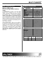
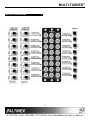
MULTI-TASKER MANUAL PART NUMBER: 400-0226-003 MT105-110/MT105-111 8/16-IN, 8-OUT SYNC MATRIX SWITCHER CARDS FOR MULTI-TASKER USER’S GUIDE MULTI-TASKER TABLE OF CONTENTS Page PRECAUTIONS / SAFETY WARNINGS ...............3 GENERAL ..........................................................3 INSTALLATION..................................................3 CLEANING.........................................................3 FCC / CE NOTICE..............................................3 ABOUT YOUR MT105-110/111.............................4 TECHNICAL SPECIFICATIONS............................4 DESCRIPTION OF MT105-110/111 ......................5 APPLICATION DIAGRAM .....................................6 INSTALLING YOUR MT105-110/111 ....................8 OPERATION ........................................................8 RS-232 CONTROL.............................................8 DESCRIPTION OF COMMANDS .......................8 SUMMARY OF COMMANDS. ..........................13 TROUBLESHOOTING GUIDE ............................13 ALTINEX POLICY ..............................................14 2 2 MULTI-TASKER PRECAUTIONS / SAFETY WARNINGS • 1 Please read this manual carefully before using your MT105-110/111. Keep this manual handy for future reference. These safety instructions are to ensure the long life of your MT105-110/111 and to prevent fire and shock hazard. Please read them carefully and heed all warnings. 1.1 GENERAL • Qualified ALTINEX service personnel, or their authorized representatives must perform all service. 1.2 INSTALLATION • • • • • To prevent fire or shock, do not expose this unit to rain or moisture. Do not place the MT105-110/111 in direct sunlight, near heaters or heat radiating appliances, or near any liquid. Exposure to direct sunlight, smoke, or steam can harm internal components. Handle the MT105-110/111 carefully. Dropping or jarring can damage the card. Do not pull the cables that are attached to the MT105-110/111. Insert the card carefully into the slots of the Multi-Tasker™ without bending any edges. 1.3 CLEANING • Clean only the connector area with a dry cloth. Never use strong detergents or solvents, such as alcohol or thinner. Do not use a wet cloth or water to clean the card. Do not clean or touch any component or PCB. 1.4 FCC / CE NOTICE • This device complies with part 15 of the FCC Rules. Operation is subject to the following two conditions: (1) This device may not cause harmful interference, and (2) this device must accept any interference received, including interference that may cause undesired operation. 3 3 This equipment has been tested and found to comply with the limits for a Class A digital device, pursuant to Part 15 of the FCC Rules. These limits are designed to provide reasonable protection against harmful interference when the equipment is operated in a commercial environment. This equipment generates, uses, and can radiate radio frequency energy and, if not installed and used in accordance with the instruction manual, may cause harmful interference to radio communications. Operation of this equipment in a residential area is likely to cause harmful interference in which case the user will be required to correct the interference at his own expense. Any changes or modifications to the unit not expressly approved by ALTINEX, Inc. could void the user’s authority to operate the equipment. MULTI-TASKER ABOUT YOUR MT105-110/111 2 TECHNICAL SPECIFICATIONS MT105-110/MT105-101 8/16-in 8-out Sync Matrix Switcher Cards FEATURES/ DESCRIPTION GENERAL Inputs External Input Connectors Outputs Output Connector Compatibility The MT105-110/111 16-in/8-in, 8-out Sync Matrix Switcher card is designed for use in the MultiTasker enclosure to allow the routing of computer and broadcast video in audio/visual presentation systems. When installed in the enclosure (MT100100), this card enables 16 composite video sources to be connected and switched to eight different display or recording devices. Inputs are selected via easy-to-use ASCII commands from a control system or computer connected to the RS-232 port of a Multi-Tasker™ enclosure. 3 MT105-110/111 8/16 8/16 BNC Female 8 8 BNC Female Composite Sync Using 1 Card Using 2 Cards H+V Sync Table 1. MT105-110/111 General MECHANICAL MT105-110/111 Enclosure Slots Required Three Weight 1.0 lb (0.45 kg) Connector Panel Black T° Operating 10°C-50°C T° Maximum 75°C Humidity 90% non-condensing MTBF (calc.) 40,000 hrs Table 2. MT105-110/111 Mechanical Multiple MT105-110/111 cards can be installed in the enclosure to provide additional functionality. For example, two cards can be used to handle the two components of an RGBHV signal (HSync and VSync. When using these cards to switch RGBHV format signals, it is possible to adapt the 5 BNC connectors to a VGA-type, 15-pin HD connector using ALTINEX adapter cables, such as part # MS8102CA ELECTRICAL Input Signals Impedance Analog/TTL Output Signals Impedance MT105-110/111 10K Ohms 1.5 – 5V max. 22 Ohms Power Power from Power +6V -6V MT100-100 Consumption MT105-110 450mA 380mA 5 watts MT105-111 200mA 150mA 2.1 watts Table 3. MT105-110/111 Electrical 4 4 MULTI-TASKER DESCRIPTION OF MT105-110/111 4 5 5 MULTI-TASKER APPLICATION DIAGRAM 5 6 6 MULTI-TASKER Block Diagrams: Internal View of MT105-110/111 7 7 MULTI-TASKER INSTALLING YOUR MT105-110/111 Commands such as [ON], [OFF], and [IO] that end in "S" will be saved into memory. Commands not ending in "S" will still be executed but will not be restored when the system is reset (power off & power on again). 6 Step 1. Slide the MT105-110/111 into an available slot in the Multi-Tasker™ Enclosure in order to connect to the bus. Make sure that the MT105-110/111 card fits into place. Secure the card to the MultiTasker™ by tightening the retainer screws located on the top and bottom of the MT105-110/111 card. 7.2 DESCRIPTION OF COMMANDS Each command consists of three parts: function, card ID, and unit ID. [Function, Card ID, Unit ID Example: Step 2. Connect a coaxial cable from the video source to the input connector of the MT105-110/111. Connect the output connectors of the MT105-110/111 to the display devices through a coaxial cable [VERC3U2] Step 3. Starting from the left, identify the slot number where the MT105-110/111 card is plugged into the Enclosure and note that it for RS-232 control. For function, see a detailed explanation under each command description. OPERATION VER = function C3 = Card ID U2 = Unit ID Card ID is an assigned value from 1 to 19 (1 to 8 or 1 to 2 depending on which enclosure is being used); based on which slot the card is put in. Card ID 0 (C0) is used for the controller (see user’s guide for the MT100-100). Changing the position of a card will significantly affect the commands recorded on software definitions or a third party control system. 7 7.1 RS-232 CONTROL When used in the Multi-Tasker™ Enclosure, the MT105-110/111 has many advanced remote control capabilities, which are accessible through standard RS-232 communication. The actual controlling can be accomplished through a computer control system or any other device capable of sending RS-232 commands. Unit ID has a value from 0 to 9. Unit ID 0 should be used for single unit operation. If the Unit ID is set to 0, then each command can be used without Ui (use command [SETU0]; see user’s guide for the MT100-100). Example: 7.1.1 RS-232 INTERFACE [VERC3]: for unit ID zero [VERC3Ui]: for unit ID other than zero [VERC3]: equivalent to [VERC3U0] The RS-232 commands for the MT105-110/111 are in a simple ASCII character format 1. 2. Square brackets “[ ]” are part of the command. Use uppercase letters for all commands. 1. [VER] This command displays the software version and card type for the MT105-110/111 card After processing a command, an OK or ER string will be returned as feedback if "F" is included at the end of a command string or if the unit ID is zero. Command Format: [VERCnUi Cn = card ID (n = slot # from 1 to 19) Ui = Unit ID (i = # from 0 to 9) (refer to the MT100-100 user’s guide for explanation 8 8 MULTI-TASKER Input8 is connected to Output5 and Output5 is disabled Example: If one MT105-110/111 card is in slot #2 of unit 3: Input7 is connected to Output6 and Output6 is disabled When sending command [VERC2U3], the MultiTasker™ Enclosure will return feedback as MT105-111 690-0126-011. Input10 is connected to Output7 and Output7 is disabled Input16 is connected to Output8 and Output8 is disabled 2. [C] This command displays the status of the card and connections of the Matrix Switcher. Note: If there is no card in slot #2 of unit 3,sending the [C2U3] command will not return any feedback. Command Format: [CnUi] Cn = card ID (n = a slot # from 1 to 19) ERROR CODES (1 to 8 for MT100-101 or 1 to 4 for MT100-106) ER01: CPU Error Ui = unit id (i = 0 to 9) (refer to the MT100-100 user’s guide for explanation) This type of error indicates that the CPU is not working properly. Example: ER02: I²C Communication Error If one MT105-110/111 card is in slot #2 of unit 3 with output 1, 2 and 3 ON: This means that the communication between the MT105-110/(111) card and its serial device has failed. When sending command [C2U3], feedback will be returned as: ER03: RS485 Communication Error Config:16X8 In1 Out1 ON In2 Out2 ON In1 Out3 ON In2 Out4 OFF In8 Out5 OFF In7 Out6 OFF In10 Out7 OFF In16 Out8 OFF This type of error is a communication error between the MT105-110/(111) card and the controller of the Multi-Tasker™ Enclosure. [CiS] This command saves card status such as ON/OFF, IN/OUT connection as default settings 3. [IO] Description of Feedback: Input1 is connected to Output1 and Output1 is enabled This command will connect input x with output y, but the user needs to use the [ON] command to enable this output. Input2 is connected to Output2 and Output2 is enabled Command Format: [IxOyCnUi] Input1 is connected to Output3 and Output3 is enabled Input2 is connected to Output4 and Output4 is disabled 9 9 MULTI-TASKER Ix = select input x (x is # from 1 to 16) [ONmGkUiS]: for a group of cards Oy = connect to output y (y is # from 1 to 8) This command enables output "m" for each card in group "k" of unit "i". Cn = card ID number (n is # from 1 to 19) (1 to 8 for MT100-101 or 1 to 4 for MT100-106) m = card output (m = # from 1-8) Ui = unit ID, i is # from 0 to 9). (Refer to MT100100 user’s guide to set Unit ID). k = group number (k = # from 1-9) i = unit number (i = # from 0-9) S = saves command to memory S = saves command to memory Example: Example: To connect input 4 to output 2 (card 2 of unit 3), use the [I4O2C2U3] command. 1. [ON1G5U1]: Turns ON output 1 for each card in group5 of unit 1. [ImO*…]. This command connect input m to all outputs. 2. [ONG5U1]: Turns ON all outputs for each card in group5 of unit 1. 4. [ON] [ON…..P]: sets path This command enables one or more outputs of a single card or a group of cards This command will set the path for the output, but it is not active until the switch command is executed ( [SW] ). Commands ending in "P" are not executed immediately. The path for outputs on multiple cards or the same card can be loaded. [ONmCnUiS]: for a single card This command enables output “m” without affecting any other outputs. Default when plugged in = ALL OFF Command Format: [ONmCnUiP] m = Output number (m = 1 to 8) m = Output number (m =1 to 8) n = Card ID number (n = 1 to 19) (1 to 8 for MT100-101 or 1 to 4 for MT100-106) n = card ID No. (n = a slot # from 1 to 19) (1 to 8 for MT100-101 or 1 to 4 for MT100-106) i = Unit ID number (i = 0 to 9) P = path S = saves command to memory Example: Example: If 2 cards are at slot 6 and 7 of unit 3: 1) [ON12C5U3]: Turns ON only output 1 and 2 of the MT105-110/(111) card located in slot #5 of the MT100-100 Enclosure with unit ID3. To enable output 1 and 2 of card 6 and output 3 and 4 of card 7 simultaneously, use the following commands: [ON12C6U3P] 2) [ON3C5U3]: Turns ON only output 3 of the MT105-110/(111) card located in slot #5 of the MT100-100 Enclosure with unit ID3. After the [ON12C5U3] and [ON3C5U3] commands have been executed, output 1, 2 and 3 will be ON. [ON34C7U3P] [SW] If "F" is included use the [ONmCnUiPF] command or the [ONmCnUiFP] command. 3) [ONC5U3]: Turns ON all outputs of the card. 10 10 MULTI-TASKER m = card output (m = # from 1-8) [ON…..F]: feedback After processing a command, an OK or ER will be returned as feedback if "F" is included at the end of a command string or if the unit ID is zero. k = group number (k = # from 1-9) (1 to 8 for MT100-101 or 1 to 4 for MT100-106) Example: S = saves command to memory i = unit number (i = # from 0-9) [ON1C2U3F]: if path is not set Example: [ON1C2U3PF]: if path is set 1. [OFF1G5U1]: Turns OFF output 1 for each card in group5 of unit 1. 5. [OFF] 2. [OFFG5U1]: Turns OFF all outputs for each card in group5 of unit 1. This command disables one or more outputs of a single card or a group of cards. [OFF…..P]: sets path [OFFmCnUiS]: for a single card n = card ID No. (n = slot # from 1 to 19) (1 to 8 for MT100-101 or 1 to 4 for MT100-106) This command will set the path for the output, but it is not active until the switch command is executed ([SW]). Commands ending in "P" are not executed immediately. The path for outputs on multiple cards or the same card can be loaded. I = Unit ID number (i = 0 to 9) Command Format: [OFFmCnUiP] S = saves command to memory m = output number (m =1 to 8) [OFFCnUi]: Turns OFF all outputs of the card n = card ID No. (n = a slot # from 1 to 19) (1 to 8 for MT100-101 or 1 to 4 for MT100-106) This command disables output “m” without affecting any other outputs. m = output number (m = 1 to 8) Example: P = path 1) If card 5 of unit 3 has output 1, 2 and 3 ON: Example: a) [OFF1C5U3]: Turns OFF output 1 while output 2 and 3 remain ON. If 2 cards are at slot 6 and 7 of unit 3: b) [OFF23C5]: Turns OFF output 2 and 3. To enable output 1 and 2 of card 6 and output 3 and 4 of card 7 simultaneously, use the following commands: 2) If card 5 of unit 3 has output 1, 2, 3, 4, 5, 6, 7 and 8 ON: OFF12C6U3P] a) [OFFC5U3]: Turns OFF all outputs, which is equivalent to [OFF12345678C5U3]. [OFF34C7U3P] [SW] [OFFmGkUiS]: for a group of cards If "F" is included use the [OFFmCnUiPF] command or the [OFFmCnUiFP] command. This command disables output "m" for each card in group "k" of unit "i". [OFF…..F]: feedback Command Format: [OFFmCnUiP] After processing a command, an OK or ER will be returned as feedback if "F" is included at the end of a command string or if the unit ID is zero. 11 11 MULTI-TASKER Example: [CLRCnUi]: for a single card n = Card ID number (n = 1 to 19) (1 to 8 for MT100-101 or 1 to 4 for MT100-106) [OFF1C2U3F]: if path is not set [OFF1C2U3PF]: if path is set Ui = Unit ID number (i = 0 to 9) 6. [SW] – Switch Note that all outputs will be connected to input1. The switch command immediately connects inputs and outputs, which were previously set with the path command on this card or any other cards in the MT100-100. [CLRGkUi]: for a group of cards Gk = group number (k = # from 1-9) Ui = unit number (i = # from 0-9) Example: Example: [ON12C6U3P] [SW] a) To clear group #1, send the [CLRG1U1] command. This command clears the members for the specified group only. The system will return feedback as OK if the unit ID is zero. b) To clear all groups of unit 1, send the [CLRG[U1] command. [ON34C7U3P] OK or ER will be returned as feedback if "F" is included at the end of a command string or if the unit ID is zero. 7. [WR] This command groups multiple cards in the MT100-100 Enclosure. Each unit contains a maximum of nine groups. 9. [G] Command Format: [WRCn…GkUi] n = card ID No. (n = slot # from 1 to 19) (1 to 8 for MT100-101 or 1 to 4 for MT100-106 This command is used to request group data. With the command, the user can identify which input or output of a particular group is on. k = group number (k = # from 1-9) Command Format: [GkUi] i = unit number (i = # from 0-9) Gk = group number (k = # from 1-9) Ui = unit number (i = # from 0-9) Example: Example: To group card #1, 2, and 3 as group 5 of unit #1, send the [WRC1C2C3G5U1] command. After executing this command, card 1, 2, and 3 will be grouped as group 5 of unit 1. If group 1 has DA Cards with output 1, 2 and 3 on, while group 2 has SW Cards with input 2 on: 1) [G1]: will return feedback as [On123G1]. OK or ER will be returned as feedback if "F" is included at the end of a command string or if the unit ID is zero. 2) [G2]: will return feedback as [On2G2]. 8. [CLR] This command clears the members for a single group or for all nine groups. 12 12 MULTI-TASKER 10. [RD] TROUBLESHOOTING GUIDE This command displays the members in each group. 8 We have carefully tested and have found no problems in the supplied MT105-110/(111); however, we would like to offer suggestions for the following: Command Format: [RDGkUi] k = group number (k = # from 1-9) NO DISPLAY Cause 1: The source has a problem. i = unit number (i = # from 0-9) member = C1 - C19 (card 1 to 19) (1 to 8 for MT100-101 or 1 to 4 for MT100-106) Solution: Check the source and make sure, that there is a signal present and all source connections are correct. If the source is working and there is still no display, see Cause 2. Cause 2: The card input is not selected. Solution: Select the card input. See RS-232 accessible commands in section 7.If no display is present see Cause 3. Cause 3: Cable connections to the destination are incorrect. Example: To read member data for group 5 of unit 1, send the [RDG5U1] command. The system will return feedback as C1C2C3 G5U1 11. [HELP] This command displays all available commands for RS-232 control. 7.3.SUMMARY OF COMMANDS. Solution 1: Make sure that cables are connected properly. Also, make sure that the continuity and wiring are good. If there is still no display present, see Cause 4. 1) [VER]: Receives software version 2) [C]: Receives status of the card 3) [IO]: Connects the input to the output 4) [ON]: Turns on one or more outputs for a single card or a group of cards Cause 4: 5) [OFF]: Turns off one or more outputs for a single card or a group of cards Solution 1: Make sure that the display is powered. If there is still no display, call ALTINEX at (714) 990-2300. 6) [SW]: Switch (outputs the preloaded buffer) 7) [WR]: Groups multiple cards 8) [CLR]: Clears members of a single group or all groups 9) [G]: Requests group data 10) [RD]: Displays the members in each group. 11) [HELP]: Displays all commands 13 13 The display has a problem. MULTI-TASKER ALTINEX POLICY 9 9.0 LIMITED WARRANTY / RETURN POLICY Please see the Altinex website at www.altinex.com for details on warranty and return policy. 9.1 CONTACT INFORMATION ALTINEX, INC. 592 Apollo Street Brea, CA 92821 USA TEL: 714-990-2300 TOLL FREE: 1-800-ALTINEX WEB: www.altinex.com E-MAIL: [email protected] FAX: 714-990-3303 14 14