1
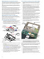
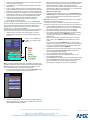
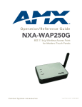
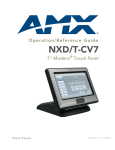
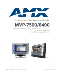
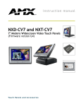
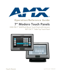
Installation Guide
NXA-WC80211GCF
For more detailed installation and operating instructions, refer to the related
MVP, CV7, and CV10 Instruction Manuals, available on-line at www.amx.com.
PIFA antenna
with metal plate
FIG. 1 NXA-WC80211GCF wireless card
Overview of the NXA-WC80211GCF Card
This interface card (FG2255-07) is a 2.4 GHz WiFi LAN CF Card which
upgrades a Modero panel’s wireless RF capabilities from 802.11b to 802.11g.
This card also provides the end-user with several new methods of wireless
encryption and data security such as WPA and WPA2. In addition to being
backwards compatible with 802.11b networks, this card can be installed in all
current MVP, CV7, and CV10 panels. To fully utilize these newer wireless
security features, this card must be used in tandem with the latest Modero
firmware upgrade available at www.amx.com.
Specifications
NXA-WC80211GCF Specifications (Cont.)
Power
Consumption:
• @ 802.11b communication:
- RX: 270 mA
- TX: 435 mA
- Standby: 240 mA
• @ 802.11g communication:
- RX: 270 mA
- TX: 460 mA
- Standby: 240 mA
Radio Data Rate:
• 802.11g compliant: 1, 2, 5.5, 11 (DSSS/CCK); 6, 9, 12, 18, 24, 36, 48,
and 54 (OFDM) Mbps data rates
Radio Technology:
• Using 802.11b communication: DSSS (Direct Sequence Spread
Spectrum)/CCK (Complementary Code Keying)
• Using 802.11g communication: DSSS/CCK, OFDM (Orthogonal
Frequency Division Multiplexing
Receiver Sensitivity: • Using 802.11b communication @ FER<8%:
1 Mbps: -94 dBm (max)
2 Mbps: -93 dBm (max)
5.5 Mbps: -92 dBm (max)
11 Mbps: -90 dBm (max)
• Using 802.11g communication @ PER <10%:
6 Mbps: -87 dBm (max)
9 Mbps: -86 dBm (max)
12 Mbps: -86 dBm (max)
18 Mbps: -84 dBm (max)
24 Mbps: -82 dBm (max)
36 Mbps: -78 dBm (max)
48 Mbps: -74 dBm (max)
54 Mbps: -72 dBm (max)
RF Frequency
Ranges:
• Using 802.11b & g communication:
Europe ETSI: 2.412 ~ 2.472 GHz
France: 2.457 ~ 2.472 GHz
Japan (802.11b): 2.412 ~ 2.484 GHz
Japan (802.11g): 2.412 ~ 2.472 GHz
North America: 2.412 ~ 2.462 GHz
Standard
Conformance:
•
•
•
•
•
IEEE 802.11b
IEEE 802.11g
IEEE 802.11e
IEEE 802.11i
Wi-Fi (WPA and WPA2)
Touch Panel
Compatibility:
•
•
•
•
•
•
•
MVP-7500 (FG5965-01)
MVP-8400 (FG5965-02)
MVP-8400i (FG5965-04)
NXD-CV10 (FG2259-02)
NXT-CV10 (FG2259-01/03)
NXD-CV7 (FG2258-02)
NXT-CV7 (FG2258-01)
Transmit Output
Power:
• 802.11b communication: 12 +-1 dBm (1, 2, 5.5, 11 Mbps)
• 802.11g communication: 12 +-1 dBm (6, 9, 12, 18, 24, 36, 48,
and 54 Mbps)
Wireless LAN
Security:
•
•
•
•
•
•
•
EAP-FAST
EAP-LEAP
EAP-PEAP
EAP-TLS
EAP-TTLS
WEP 64 & 128
WPA-PSK
Included
Accessories:
•
•
•
•
•
Double-sided adhesive tape
Mounting Template cutout (62-2255-04)
NXA-WC80211GCF Quick Start Guide
Two Alcohol cleaning pads
Wireless CF card with wireless antenna
Other AMX
Equipment:
• NXA-WAP250G Modero Wireless Access Point (FG2255-50)
• Upgrade Compact Flash memory (factory programmed with firmware).
These Compact Flash cards now come with panel-specific firmware
for the MVP, CV7, and CV10 touch panels.
NXA-WC80211GCF Specifications
Dimensions (HWD):
• 0.22" x 1.68" x 2.40" (5.6 mm x 42.80 mm x 61.0 mm)
Weight:
• 19.50 grams (0.043 lbs)
Description:
• Wireless LAN Compact Flash Card with external PIFA antenna.
• Features enterprise-class security such as WPA and WPA2 security.
Features:
•
•
•
•
•
•
•
•
•
•
Compact Flash Type I form factor
Enhanced range and throughput
Features wireless security such as: WPA, WPA2 and WEP
Field-installable
Incorporates DSSS and OFDM radio technology
Operates at ISM frequency bands of 2.4 GHz, while providing data
transfer speeds of up to 54Mbps.
Support for IEEE 802.11b and 802.11g
Supports Advanced Encryption Standard (AES) 64-bit and 128-bit data
encryption, along with an Re4 encryption cipher (64/128-bit)
Supports authentication methods such as: EAP-FAST, EAP-LEAP,
EAP-PEAP, EAP-TLS, and EAP-TTLS
Supports Wired Equivalent Privacy (WEP) 64-bit and 128-bit data
encryption (known to the on-board firmware as Static WEP)
Wireless Compact Flash Card
Antenna Type:
• External PIFA antenna (factory-installed)
Bus Interface:
• Compact Flash Type I
Certifications:
• FCC Part 15 Class B, CE, IC, TELEC, and Wi-Fi
Media Access
Control Technique:
• CSMA/CA with ACK
Media Access
Control Techniques:
• Using 802.11b DSSS communication:
DBPSK @ 1 Mbps
DQPSK @ 2 Mbps
CCK @ 5.5 Mbps
• Using 802.11g OFDM communication:
BPSK @ 6 and 9 Mbps
QPSK @ 12 and 18 Mbps
16-QAM @ 24 and 36 Mbps
64-QAM @ 48 and 54 Mbps
Before You Begin - Upgrade the Firmware
Network
Architecture:
• Infrastructure mode (Client-to-Access Point)
Operating
Channels:
• Using 802.11b & g communication:
- 04: (Ch 10 - 13) - France
- 11: (Ch 1 - 11) - North America (USA)
- 13: (Ch 1 - 13) - Europe ETSI
- 13: (Ch 1 - 13) - Japan (802.11g)
- 14: (Ch 1 - 14) - Japan (802.11b)
Note: Each panel should be updated using its associated panel-specific kit file
(SW5965_01.kit for the MVP-7500, SW5965_02.kit for the MVP-8400,
SW2258_02 for the CV7, and SW2259_02 for the CV10).
Note: To alter the card’s default country code (North America),
please contact an AMX Technical Support representative for
detailed procedures and information.
Operating
Environment:
• Temperature: 0°C ~ 45°C (32°F to 113°F) (operating) and
-20°C ~ 70°C (-4°F to 158°F) (storage)
• Humidity: (non-condensing) 5% ~ 90% RH (operating) and
(non-condensing) 5% ~ 95% RH (storage)
Operating Voltage:
• 3.3V + 5% I/O supply voltage
1.
Upload the latest panel-specific kit file to your existing MVP, CV7, or CV10
touch panel and then confirm the firmware file update was successful.
Refer to your panel’s instruction manual for detailed communication and Kit
file upload procedures.
This new firmware file provides both backwards compatibility with the previous
802.11b cards and new security protocols for the new 802.11g wireless CF card.
Caution: If you don’t first update the firmware file on the panel,
before proceeding with the card upgrade process, you will be
required to configure NetLinx Studio to communicate with the
target panel via a direct USB connection. In this communication
scenario, your PC acts as a Virtual NetLinx Master establishing a
secure USB connection to the target panel and then uploading the
new Kit file.
1
NXA-WC80211GCF Card and Antenna Overview
Step 2: Install the new 802.11g CF Card and Antenna (MVPs)
This upgrade kit requires that pre-existing panels first be removed from their
current location (surface, wall or docking station) before an installer can access
the internal circuit boards and upgrade a pre-existing 802.11b wireless CF
card.
1.
MVP panels require the use of a cardboard cutout (Mounting Template) to
properly position the metal antenna plate onto the inner surface of the unit’s
rear plastic housing.
CV7 and CV10 panels only require locating the Compact Flash’s metal cover
plate on the main circuit board and then adhering the terminal antenna
connector to that location using the included double-sided adhesive tape.
Note: If the CF metal cover plate is not present over the wireless card slot on a
CV7 or CV10 panel, you can use the adhesive tape to secure the terminal
antenna to the surface of the new card (atop the product label).
The procedures for upgrading a CF card on an MVP is identical for both
MVP-7500 and MVP-8400 panels. The procedures for upgrading/installing the
new CF card are also similar across all referenced NXT panels and NXD
panels as a group (differences arise from their housing).
NXA-WC80211GCF Installation into MVP Panels
Upgrading the wireless CF card on an MVP involves opening the panel
enclosure, removing the existing card, replacing it with the upgrade, and then
closing the panel enclosure, as described below.
2.
3.
4.
5.
6.
Note: Batteries should be removed prior to upgrading the card.
7.
Step 1: Access the MVP’s Internal Components
1.
2.
Carefully detach any connectors from the touch panel and then gently
place the MVP LCD facedown onto a soft cloth to expose the battery
compartment. This step helps prevent scratching of the LCD.
Slide the Battery Compartment cover (FIG. 2) away from the metal plate
to expose the internal battery compartment (2 battery slots).
Discharge any static electricity from your body by touching a grounded
metal object and then locate the wireless card slot on the main board
(FIG. 3).
Place the circuit board (A in FIG. 2) on a flat level surface so that the IR
Emitters are pointing away from you.
Insert the tip of a grounded flat-head screwdriver into one of the card
removal grooves (located on either side of the existing CF card), and
gently pry it out of the slot. Repeat this process on the opposite card
removal groove. This alternating action causes the pre-existing card to
"wiggle" away from the on-board connector pins.
Slip your finger into the gap (between the card and the circuit board),
firmly grab the old card by its sides, and then carefully pull it up and out
from the slot. An angular removal of the card is required because one of
the housing’s latch attachments blocks the slot opening.
USE CARE WHEN PULLING UP ON THE CARD.
Flip over the MVP’s rear housing (B in FIG. 2) so that the internal support
structures are visible and then lay it directly in front of the circuit board
such that the battery compartment is furthest away from you. This
placement provides contact of both top rims (FIG. 3).
Remove one of the included alcohol pads and use it to thoroughly clean
both the rear housing’s inner surface (bottom right corner) and the
underside of the terminal antenna’s metal pate (FIG. 1). These surfaces
must be properly cleaned to provide good adhesion for the later
installation of the wireless antenna.
Place the included Mounting Template cutout along the bottom right
corner of the rear housing (FIG. 3). Use the housing’s inner support
structures to fix the template into place.
Internal
Support
Structures
Mounting Template
Battery Compartment
cover
Unscrew these
two housing
screws to remove
the circuit board
housing
B
Bottom rim of
outer housing
MVP outer
housing (rear)
A
Circuit board
housing
attachment
locations (4)
DO NOT
REMOVE
these screws.
They secure
the LCD.
This grey trim fits
inside the grooves
and around the
edges of the panel.
Wireless
Card
Slot
FIG. 3 Installing the Mounting Template in the correct location
8.
9.
FIG. 2 Removing the MVP enclosure (housing)
3.
4.
5.
6.
7.
2
Remove any previously installed MVP-BP batteries prior to removing the
outer housing.
Use a grounded Phillips-head screwdriver to remove the two housing
screws shown in FIG. 2. Once done, place these screws aside.
Grasp the bottom rim of the outer housing (just above the MVP interface
connector - Blue arrows in FIG. 2) and in a single motion, carefully pull
the bottom rim up and then out (away from the IR Emitter) to expose the
internal circuit board (A in FIG. 2). It might be necessary to repeat this
process along the bottom and sides of the housing as well.
Remove the dark grey trim from the top rim of the board (FIG. 2).
After you have completed the upgrade process, complete the installation
by continuing to Step 3: Close and Re-secure the MVP Panel
Enclosure section on page 3.
Remove the new NXA-WC80211G CF card from it’s anti-static bag.
Grip the sides of the new wireless card and insert it firmly into the slot
opening (at a downward angle) until the contact pins are completely
inside the card and securely attached to the pin sockets.
Note: You must precisely align the double-sided tape to the surface of the
terminal antenna’s metal plate in order to later secure the antenna within
the pre-defined installation area outlined by the included Mounting
Template.
10.
Carefully peel-off one side of the included double-sided tape and adhere
the adhesive side to the surface of the antenna’s metal plate.
11.
Locate the T-shaped opening on the left of the cutout and make sure the
antenna wire is located along the left side of the cutout (FIG. 4).
Grip the antenna by its sides and carefully peel-off the remaining
protective film on the double-sided tape.
Align the antenna into the long vertical groove in the cutout and firmly
adhere it to the inner surface of the housing. Make sure the wire is
threaded along the left side of the cutout, this helps in the removal of the
cutout.
12.
13.
Installation Guide
NXA-WC80211GCF
8.
Mounting
Template
Cutout
Wireless Compact Flash Card
Grab the battery cover and align it over the edges of the battery compartment. Apply downward pressure to the traction grooves on the Battery
Compartment cover and slide it back towards the metal plate to reinstall the
cover (FIG. 5).
Note: Once the Wireless CF Card has been installed, be careful opening the
MVP’s housing so that the CF card’s antenna (mounted to the inside of the
bottom housing) is not accidentally damaged or disconnected.
NXA-WC80211GCF Installation into Modero NXT Panels
Upgrading the wireless CF card in NXT-CV7/10 Table Top Touch Panels involves
removing the outer housing (with speaker plate), installing the new 802.11g
wireless card, and then placing the outer housing back onto the NXT panel, as
described below.
Step 1: Remove the Existing NXT Outer Housing
1.
2.
FIG. 4 Adhering the antenna plate to the MVP outer housing
14.
15.
3.
With the antenna now securely attached to the MVP’s inner housing,
remove the cutout by carefully pulling up on the cutout and threading the
antenna wire through the T-shaped opening.
To complete the upgrade process, close and re-secure the panel enclosure
using the procedures in the following step.
Step 3: Close and Re-secure the MVP Panel Enclosure
Note: When re-securing the enclosure, care must be taken not to pinch the
antenna wire in the housing.
1.
2.
Carefully detach all connectors from the rear of the touch panel and then
gently place the touch panel LCD facedown onto a soft cloth to expose the
under-side of the base (FIG. 6). This step helps prevent scratching of the
LCD.
Tilt the base forward so that both the bottom surface and Housing Screws
are easily accessible and then carefully remove the four plastic adhesive
feet.
While holding the outer housing and base plate at a 45° angle (to prevent it
from sliding), use a grounded Phillips-head screwdriver to remove the four
Housing Screws (FIG. 6).
Unscrew these four
Housing Screws
to remove the
Circuit Board Cover
Base
Reinstall the dark grey trim along the top rim of the board (B in FIG. 5).
While angling the top rim of the MVP’s rear outer housing (A in FIG. 5)
down toward the IR Emitters, insert the four outer housing latches into their
corresponding attachment locations along the top rim of the MVP panel
(two on either side of the IR Emitters).
45°
Outer housing latches (4)
A
DO NOT REMOVE these screws
They secure the plastic base front cover.
Hinge Brackets (2)
FIG. 6 Location of the attachment screws underneath an NXT panel base
Note: Reference the location of the four plastic adhesive "feet". Once the
outer housing is placed back onto the panel, these "feet" must be placed
back in their original locations so they can fit into their provided openings on
a Battery Base.
B
4.
5.
CF memory card
Wireless CF card
Rotate the panel back over (while gripping the entire unit and outer
housing) and rest the base back onto a flat surface.
Gently tilt the LCD panel backwards to expose the Tilt Bracket/Speaker
assembly (FIG. 7).
4 Outer housing latch
attachment locations
Tilt Bracket/Speaker assembly
FIG. 5 Wireless CF card and outer housing latch attachment locations
Tilt Bracket Screws (2)
3.
These two screws must
first be removed before
being able to remove
the outer housing.
4.
5.
6.
7.
While firmly holding the top rims together, gently press down on the bottom
ridge of the outer housing (at the latch locations) and verify that each
housing latch fits within its corresponding attachment location on the board.
When done, complete the insertion of the remaining housing latches.
Verify that the notches along the bottom of the plastic battery slot separator
strip also fit into the three provided alignment holes on the circuit board.
Firmly press down around the entire rim of the outer housing to snap the
cover back into place (FIG. 5).
Use a grounded Phillips-head screwdriver to insert and re-secure the two
housing screws removed in Step 1 (FIG. 2).
Insert any available batteries back into the battery compartment.
Outer Housing
Base
Hinge Brackets (2)
FIG. 7 Location of the attachment screws underneath an NXT panel base
3
6.
7.
8.
Locate the two screw holes at either sides of the front speaker grill and
then use a grounded Phillips-head screwdriver to remove the two Tilt
Bracket Screws (FIG. 7).
This procedure both loosens the rear Tilt Bracket cover plate (with the
AMX logo and Hinge brackets) and provides greater flexibility for the
removal of the outer housing.
Without this step, the Hinge brackets (FIG. 7) present an obstacle to the
removal of the outer housing and restrict access to the circuit board.
Tilt the LCD panel back up to gain better access to the Tilt Bracket cover
plate.
In a single motion, carefully pull both the Tilt Bracket cover plate and
outer housing up and then out (away from the LCD panel) to expose the
internal circuit board.
Step 2: Install the new 802.11g CF Card and Antenna (NXT)
1.
Discharge any static electricity from your body by touching a grounded
metal object and then locate wireless card slot on the main board (FIG. 8).
Front of panel
Tilt Bracket
cover plate
Caution: Use care when re-installing the outer housing. Improper
re-installation can cause damage to the internal speakers.
5.
6.
7.
8.
9.
While holding the circuit board cover in place, turn the panel back over
until the LCD lies facedown on a soft cloth and the under-side of the base
is exposed (FIG. 6).
Insert and secure the four Housing Screws (using a grounded
Phillips-head screwdriver) in their respective locations (FIG. 6).
Replace any adhesive plastic "feet" that might have been removed during
the removal process of the outer housing. These "feet" must be placed
back onto their original locations so they can fit into their provided
openings on the Battery Base.
Grasp both the LCD and housing and then gently rotate the entire unit
back onto a flat surface.
Insert all connectors and apply power.
NXA-WC80211GCF Installation into Modero NXD Panels
Upgrading the wireless CF card in NXD-CV7/10 WallMount Touch Panels
involves removing the rear plastic outer housing (back box), installing the new
802.11g wireless card, and then securely placing the back box back onto the
NXD panel, as described below.
Step 1: Remove the Existing NXD Outer Housing
Wireless CF Card
(Slot 2)
Memory
Card
(Slot 1)
1.
2.
CF metal plate
(with antenna
shown installed)
Carefully detach all connectors from the side of the touch panel and
remove the faceplate from the front of the panel.
Place the LCD facedown onto a soft cloth to expose the under-side of the
unit (FIG. 9). This step helps prevent scratching of the LCD.
Two (2) connector
overlay release latches
Card Removal
Grooves
FIG. 8 Location and orientation of the card slots (on both CV7/CV10 panel types)
2.
3.
4.
5.
6.
Insert the tip of a grounded flat-head screwdriver into one of the card
removal grooves (located on either side of the existing CF card), and
gently pry it out of the slot. Repeat this process on the opposite card
removal groove. This alternating action causes the pre-existing card to
"wiggle" away from the on-board connector pins.
Grip the old card by its sides and then carefully pull it out of the slot.
Remove one of the included alcohol pads and use it to thoroughly clean
both the CF metal cover (FIG. 8) and the metal pate on the underside of
the terminal antenna (FIG. 1). These surfaces must be properly cleaned
to provide good adhesion for the later installation of the wireless antenna.
Remove the new NXA-WC80211G CF card from it’s anti-static bag.
Grip the sides of the new wireless card and insert it firmly into the slot
opening until the contact pins are completely inside the card and securely
attached to the pin sockets.
Note: You must precisely align the double-sided tape to the surface of the
antenna’s metal plate in order to properly secure the antenna within to the
CF metal cover plate.
7.
8.
9.
Carefully peel-off one side of the included double-sided tape and adhere
the adhesive side to the surface of the antenna’s metal plate.
Grip the antenna by its sides and carefully peel-off the remaining
protective film on the double-sided tape.
Align the antenna atop the CF metal cover plate and press down firmly to
securely adhere it.
Note: If the CF metal cover plate is not present over the wireless card slot,
you can use the adhesive tape to secure the terminal antenna to the
surface of the new card (atop the product label).
10.
To complete the upgrade process, close and re-secure the panel enclosure using the procedures in the following step.
Step 3: Close and Re-secure the NXT Panel Enclosure
1.
2.
3.
4.
4
In a single motion, gently slide the rear Tilt Bracket cover plate back
over the tilt mechanism (located below the LCD) and (while angling the
housing downwards) slide the outer housing below the Tilt Bracket and
towards the LCD (at a downward angle).
Locate the two screw holes at either sides of the front speaker grill and
then use a grounded Phillips-head screwdriver to both insert and secure
the two Tilt Bracket Screws (FIG. 7). This procedure
re-secures the rear Tilt Bracket cover plate (with the AMX logo and Hinge
brackets).
Press the outer housing forwards until it is aligned over the outer housing
installation holes. Once installed and secured, the tilt bracket prevents
any further movement (FIG. 7).
Gently press down on the housing (toward the base) until it is securely
positioned over the circuit board and base.
Unscrew these
four pan-head
housing screws
to remove the
back box
(2 per side)
FIG. 9 Location of the securing screws and overlay on an NXD panel
3.
Firmly press down on both connector overlay release latches (located in
front of the connectors). Pressing down releases the connector overlay
from atop the connectors.
Note: The overlay connector must first be released before the rear back
box can be removed from the NXD panel.
4.
5.
Gently slide the connector overlay away from the back box housing.
Unscrew the outer housing (back box) by using a grounded
Phillips-head screwdriver to remove the two sets of pan-head Housing
Screws, located on both sides of the housing (FIG. 9).
Caution: The circuit board comes pre-wired to internal speakers located
on the inside surface of the rear back box. If the back box is removed
incorrectly, these speaker wires can become disconnected and damaged.
6.
7.
Carefully lift-off the back box housing and angle it over to the side of the
unit where the wires are connected to the circuit board (FIG. 10).
Gently lay the back box to one side of the unit. This exposes the internal
circuit board. Take care not to place undue strain on the speaker cables.
Step 2: Install the new 802.11g CF Card and Antenna (NXD)
1.
Complete the procedures outline within Step 2: Install the new 802.11g
CF Card and Antenna (NXT) section on page 4 and then continue with
the following step.
Step 3: Close and Re-secure the NXD Panel Enclosure
1.
2.
3.
4.
5.
Gently place the outer housing back onto the panel and align the four
pan-head Housing Screws holes along the edges of the outer housing.
Insert and secure the four pan-head Housing Screws back into their
pre-drilled holes by using a grounded Phillips-head screwdriver.
Slip the connector overlay back into the connector opening by inserting
the top of the overlay into the connector opening in an upwards direction.
Align the connectors to their respective locations and secure the overlay
by pushing it towards the connectors until the overlay securely snaps
back into the overlay release latches.
Re-install the faceplate back onto the panel.
Installation Guide
NXA-WC80211GCF
Caution: Speaker wires come
connected to this side of the main
board. Use caution when removing
the back box.
Note: This information can be found in either the Workspace - System name >
Define Device section of your code (that defines the properties for your panel), or
in the Device Addressing/Network Addresses section of the Tools > NetLinx
Diagnostics dialog.
7.
From within the Wireless Security section, press/toggle On the Open
(Clear Text) button. By default, this field displays an SSID entry of AMX.
8.
From within the Open (Clear Text) Settings page, press the red SSID field
to display the Network Name (SSID) keyboard and enter the SSID name
assigned to the target WAP (case sensitive).
• The card should be given the SSID used by the target WAP. If this field is
left blank, the unit will attempt to connect to the first available WAP.
By default, all WAP250Gs use AMX as their assigned SSID value.
•
9.
10.
Wireless CF card
(Slot #2 located
on the top slot)
11.
Connector Overlay must first be
removed from the side of the NXD
FIG. 10 Location of the wireless CF card connector on main board
Unsecured Panel Access using a DHCP Address
These installation procedures use an indirect communication method (via the
wireless card communicating to the Wireless Access Point (WAP)).
In determining the method of communication, the panel (except for the MVP)
always defaults first to direct Ethernet communication. If no direct connection is
detected, the panel then checks to see if there is an installed wireless card and
then communicates to the WAP using the Wireless Settings assigned within the
Wireless Settings page. The communication parameters of the wireless card
(installed within the panel) must match those of the target WAP.
1.
Complete the previous firmware update and wireless card upgrade
installation procedures.
Note: The previous 802.11b wireless card only supported Clear Text, WEP 64,
and WEP 128 encryption. The new 802.11g wireless CF card (using the latest
firmware) not only supports the previous formats but also now WPA and EAP
security protocols.
2.
Power-up the panel and navigate to Protected Setup > Wireless Settings
to open the Wireless Settings page (FIG. 11).
Modero’s
IP
connection
information
Wireless
Security
settings
12.
13.
14.
15.
•
By default, wireless Modero panels are configured for unsecured communication
to a WAP. To properly setup both a WAP250G and panel for secure
communication, you must first prepare the Modero panel and then use the
information given to fill out the fields within the WAP’s browser-based Basic
Wireless Configuration page. Although a DHCP Address can be used to
configure a secure connection, it can become more difficult to connect to a WAP
using a Dynamic IP Address if for some reason that device has lost its last
address from the DHCP Server. Using a pre-reserved IP Address (Static) can
provide the user with a consistent IP Address for connection to the target WAP.
These procedures outline the process of configuring a secure Static connection
to a target NXA-WAP250G using a WEP 128-bit encryption method
(Static WEP). The new NXA-WC80211GCF card provides additional methods
which are discussed in more detail within the specific panel’s instruction manual.
Step 1: Setup a Static IP Connection
3.
FIG. 11 Wireless Settings page
4.
5.
6.
Toggle the DHCP/Static field (from the IP Settings section) until the choice
cycles to DHCP. Except for the Host Name, all other fields are then
greyed-out.
Press the optional Host Name field to open an on-screen Keyboard and
enter the Host Name information.
Press Done after you’re finished assigning the alpha-numeric string.
Do not alter any of the remaining greyed-out fields in the IP Settings
section. Once the panel is rebooted, these values are obtained by the unit
and displayed in the DNS fields after power-up.
Press the Done button when complete. Do not leave this field blank.
From the Open (Clear Text) Settings page, press the Save button to
incorporate your new information into the panel and begin the
communication process.
From within the RF Link Info section, verify the SSID name has properly
been entered and stored.
Verify the IP Settings section fields have been properly set.
Press the Back button to navigate to the Protected Setup page.
Press the on-screen Reboot button to both save any changes and restart
the panel. Remember that you will need to navigate to the System
Settings page and configure the connection to a target Master.
After the panel restarts, return to the Wireless/Secondary Connection page
to verify the Link Quality and Signal Strength:
The descriptions are: None, Poor, Fair, Good, Very Good, and Excellent.
Secure Panel Access using a Static IP Address
2.
3.
One of the most common problems associated with connection to a WAP
arise because the SSID was not entered properly. You must maintain the
same case when entering this information. ABC is not the same as Abc.
Note: Use of the following encryption methods require the upload of a
secured certificate to the target panel prior to usage: EAP-PEAP,
EAP-TTLS, EAP-TLS, EAP-FAST.
1.
Note: Since the wireless card was replaced, all previous WAP security and
communication parameters are no longer available and must be reset.
Wireless Compact Flash Card
4.
Cycle power to the panel (this allows a detection of the new internal
wireless card).
Press the Protected Setup button (located on the lower-left of the panel
page) to open the Protected Setup page and display an on-screen keypad.
Enter 1988 into the Keypad’s password field and press Done when
finished.
Press the Wireless Settings button (located on the lower-left) to open the
Wireless Settings page.
Note: Check with your System Administrator for a pre-reserved Static IP
Address assigned to the panel. This address must be obtained before Static
assignment of the panel continues.
5.
6.
7.
8.
Toggle the DHCP/Static field (from the IP Settings section) until the
choice cycles to Static. The IP Address, Subnet Mask, and Gateway fields
then become user-editable (red).
Press the IP Address field to open an on-screen Keyboard and enter the
Static IP Address (provided by your System Administrator).
Press Done after you are finished entering the IP information.
Repeat the same process for the Subnet Mask and Gateway fields.
5
9.
10.
11.
12.
13.
Press the optional Host Name field to open an on-screen Keyboard and
enter the Host Name information.
Press Done after you are finished assigning the alpha-numeric string of
the host name.
Press the Primary DNS field to open an on-screen Keyboard, enter the
Primary DNS Address (provided by your System Administrator) and press
Done when compete. Repeat this process for the Secondary DNS field.
Press the Domain field to open a Keyboard, enter the resolvable domain
Address (this is provided by your System Administrator and equates to a
unique Internet name for the panel), and press Done when complete.
Setup the security and communication parameters between the
wireless card and the target WAP by configuring the Wireless
Settings section on this page (Step 2).
Step 2: Configure a Secure Connection to your WAP250G
Since the code key generator on Modero panels use the same key generation
formula, all panels generate identical keys for the same Passphrase. The
generators used on WAPs will not produce the same key as the Modero
generator even if you use the same Passphrase.
For this reason, we recommend FIRST creating the Current Key on the Modero
and then entering that information into the appropriate WAP250G fields.
1.
Repeat the first four actions from the preceding Step 1 to open the
Wireless Settings page and then locate the Wireless Settings section
(FIG. 12).
Wireless card communication
settings (for use with a target
WAP)
•
The card should be given the SSID used by the target WAP. If this field is
left blank, the unit will attempt to connect to the first available WAP. By
default, all WAP250Gs use AMX as their assigned SSID value.
•
One of the most common problems associated with connection to a WAP
arise because the SSID was not entered properly. You must maintain the
same case when entering the SSID information.
ABC is not the same as Abc.
4.
Note: WEP will not work unless the same Default Key is set on both the
panel and the Wireless Access Point.
For example: if you have your Wireless Access Point set to default key 4
(which was 01:02:03:04:05), you must set the panel’s key 4 to 01:02:03:04:05.
5.
Toggle the Default Key field until the you’ve chosen a WEP Key value
(from 1- 4) that matches what you’ll be using on your target WAP250G.
These WEP Key identifier values must match for both devices.
6.
With the proper WEP Key value displayed, press the Generate
button to launch the WEP Passphrase keyboard. This keyboard allows
you to enter a Passphrase (such as AMXPanel) and then
automatically generate a WEP key which is compatible only among all
Modero panels.
7.
Within this on-screen WEP Passphrase keyboard, enter a character
string or word (such as AMXPanel) and press Done when you have
finished.
• As an example, enter the word AMXPanel using a 128-bit hex digit
encryption. After pressing Done, the on-screen Current Key field displays
a long string of characters (separated by colons) which represents the
encryption key equivalent to the word AMXPanel.
8.
9.
10.
11.
FIG. 12 Wireless Security section
Note: You must first take the SSID name, Current Key string value, and
panel MAC Address information and then later enter it into the appropriate
WAP dialog fields in order to "sync-up" the secure connection. These
values must be identically reproduced on the target WAP.
2.
Toggle the blue WEP 64/WEP128 field until it reads 64 Bit Key Size or
128 Bit Key Size. The 64/128 selection reflects the bit-level of encryption
security. This WEP encryption level must match the encryption level
being used on the WAP.
Write down this Current Key string value for later entry into your WAP’s
WEP Key field (typically entered without colons) and into other
communicating panel’s Current Key field.
Leave the Authentication field reading Open (default).
Press the Save button to store this configuration and return to the
previous Wireless Settings page.
Press the Back button to navigate to the Protected Setup page and press
the on-screen Reboot button to both save any changes and restart the
panel. Remember that you will need to navigate to the System
Settings page and configure the connection to a target Master.
From within the Wireless Security section, press the Static WEP button to
open the on-screen Static WEP Settings window (FIG. 13).
FIG. 13 Static WEP Settings window
3.
Touch the red SSID field and from the Network Name (SSID) keyboard,
enter the SSID name you are using on your target Wireless Access Point
(case sensitive) and then press Done.
For full warranty information, refer to the AMX Instruction Manual(s) associated with your Product(s).
7/07
©2007 AMX. All rights reserved. AMX and the AMX logo are registered trademarks of AMX.
AMX reserves the right to alter specifications without notice at any time.
3000 RESEARCH DRIVE, RICHARDSON, TX 75082 • 800.222.0193 • fax 469.624.7153 • technical support 800.932.6993 • www.amx.com
93-2255-07
REV: E