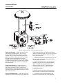
1
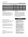
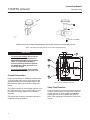
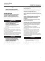
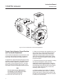
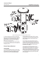
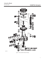
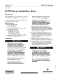
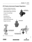
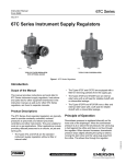
Instruction Manual
D103407X012
December 2009
1052PSV Actuator
Fisherr 1052PSV Size 60 Rotary Actuator
Contents
Introduction . . . . . . . . . . . . . . . . . . . . . . . . . . . . . . . 1
Scope of Manual . . . . . . . . . . . . . . . . . . . . . . . . . . 1
Specifications . . . . . . . . . . . . . . . . . . . . . . . . . . . . 2
Description . . . . . . . . . . . . . . . . . . . . . . . . . . . . . . . 3
Principle of Operation . . . . . . . . . . . . . . . . . . . . . . . 3
Installation . . . . . . . . . . . . . . . . . . . . . . . . . . . . . . . . 3
Conduit Connection . . . . . . . . . . . . . . . . . . . . . . . 4
Valve Flow Direction . . . . . . . . . . . . . . . . . . . . . . 4
Actuator Mounting . . . . . . . . . . . . . . . . . . . . . . . . 5
Precise Valve/Actuator Closed Position
and Turnbuckle Adjustment . . . . . . . . . . . . . . 6
Actuator Spring Adjustment . . . . . . . . . . . . . . . . 7
Initial Setting . . . . . . . . . . . . . . . . . . . . . . . . . . . . 7
Stroking Range . . . . . . . . . . . . . . . . . . . . . . . . . . 8
Accessory Mounting . . . . . . . . . . . . . . . . . . . . . . . 8
Maintenance . . . . . . . . . . . . . . . . . . . . . . . . . . . . . 10
Disassembly . . . . . . . . . . . . . . . . . . . . . . . . . . . . 11
Assembly . . . . . . . . . . . . . . . . . . . . . . . . . . . . . . . 12
Troubleshooting . . . . . . . . . . . . . . . . . . . . . . . . . . 14
Adjustable Travel Stops . . . . . . . . . . . . . . . . . . . . 14
Parts Ordering . . . . . . . . . . . . . . . . . . . . . . . . . . . . 15
Spare Parts . . . . . . . . . . . . . . . . . . . . . . . . . . . . . . 16
Parts List and Special Tools . . . . . . . . . . . . . . . . 18
Introduction
Scope of Manual
This instruction manual includes installation,
adjustment, maintenance, and parts ordering
information for the Fisher 1052PSV (Size 60)
pneumatic springanddiaphragm rotary actuator
(see figure 1).
The seismically qualified actuator design is based on
the standard Fisher 1052 size 60 actuator. The
1052PSV size 60 actuator incorporates the tilting
diaphragm rod, turnbuckle adjusting feature, upper
diaphragm casing assembly, and SS129 dual
springs mounted within a fabricated box
www.Fisher.com
W9722
Figure 1. Fisher SS84PSV4 Valve
with 1052PSV Actuator and 3610J Positioner
construction. The actuator box is designed for
standard 3610J positioner mounting. Adjustable
valve open position is provided by limiting lever
rotation with adjustable travel limit bolts in the
bottom of the fabricated actuator box.
To ensure proper assembly, the VeeBallt, valve
drive shaft, and actuator lever connections are a
missingtooth spline design, allowing oneway only
assembly.
Instructions for the control valve, positioner, and
other accessories are covered in separate
instruction manuals.
Do not install, operate, or maintain a 1052PSV
actuator without being fully trained and qualified in
valve, actuator, and accessory installation,
operation, and maintenance. To avoid personal
injury or property damage, it is important to carefully
read, understand, and follow all the contents of this
manual, including all safety cautions and warnings. If
you have any questions about these instructions,
contact your Emerson Process Management sales
office before proceeding.
Instruction Manual
1052PSV Actuator
December 2009
Table 1. Fisher 1052PSV Actuator Specifications
Operation
Travel Indication
Direct Acting: Increasing loading pressure
extends the diaphragm rod out of the spring barrel
Service: For on-off or throttling service with or
without a positioner
Graduated disc and pointer combination located
on actuator end of valve shaft, with valve ball
position indicator
Pressure Conduit Connections
Actuator Sizes
Standard: 3/4 NPT internal thread
Size 60
Maximum Diaphragm Sizing Pressure(1)
Mounting Positions
RH mount, PDTO, VeeBall rotates CCW to
close, springfail closed
2.8 bar (40 psig)
Maximum Diaphragm Casing Pressure(3)
3.4 bar (50 psig)
Approximate Weights
136 kg (300 lb)
Nominal Valve Shaft Rotation
80 degrees rotation (standard) travel stop
Controller/Positioners Available
DVC2000, DVC6000, 3620, 4190, 4150, 4160, C1
Valve Shaft Diameters
Accessories Available
31.8 mm (1-1/4 inches)
846, 646, 2625, and 67C Series, switches,
i2P100, VBL, DXP, GOt
Stroking Time
Opening requirement is 1 to 5 seconds
Additional Specifications
Material Temperature Capabilities(2)
EPDM Diaphragm: 40 to 107_C (40 to 225_F)
For casing pressure ranges and for material
identification of the parts, see the Parts List
1. Use this value to determine the maximum torque output allowed.
2. The pressure/temperature limits in this manual and any applicable standard or code limitation for valve should not be exceeded.
3. This maximum casing pressure is not to be used for normal operating pressure. Its purpose is to allow for typical regulator supply settings and/or relief valve tolerances.
DIAPHRAGM ROD,
KEY 10
LOWER SPRING SEAT,
KEY 13
NEEDLE THRUST BEARING AND RACE,
KEY 71, 72
THRUST COLLAR,
KEY 73
SPRING ADJUSTOR,
KEY 74
Figure 2. Fisher 1052PSV Actuator Adjustable Spring Seat
2
Instruction Manual
1052PSV Actuator
December 2009
Table 2. Recommended Bolting Torques
Description, Key Number
Size
Wrench Size
NSm
lbfSft
Diaphragm Casing, 5
3/8-24
9/16
27
20
Casing to Actuator Box, 7, 8
3/8-16
9/16
41
30
Diaphragm Plate to Rod, 9
3/4-16
5/8 Allen
102
75
Rod end bearing locknut, 16
5/8-18
15/16
61
45
Rod end bearing to lever, 18
5/8-11
15/16
163
120
Lever Clamp, 28
5/8-11
15/16
163
120
Cover, 34
1/2-13
3/4
81
68
7/8-14-LH
15/16
163
120
Turnbuckle locknut, 58
Description
Installation
The 1052PSV diaphragm rotary actuator is a
pneumatic spring-return actuator for use with the
SS84PSV4 rotary-shaft control valve. The
1052PSV actuator can be used for on-off service, or
it can be used for throttling service when equipped
with or without a valve positioner. The 1052PSV
actuator spring is adjustable (see figure 2).
When an actuator and valve body are shipped
together, the actuator is normally mounted on the
valve. Follow the valve body instructions when
installing the control valve in the pipeline, and then
perform the procedures presented in the Loading
Connection section. If the actuator is shipped
separately or if it is necessary to mount the actuator
on the valve, perform the procedures presented in
the Actuator Mounting section.
WARNING
Principle of Operation
The diaphragm rod moves down as loading pressure
is increased on top of the diaphragm. As the loading
pressure is decreased, the spring forces the
diaphragm rod upward.
The spring and diaphragm have been selected to
meet the requirements of the application and, in
service, the actuator should produce full travel of the
valve with the diaphragm pressure as indicated on
the nameplate.
Consult the separate positioner instruction manual
for actuator principle of operation with positioner.
Always wear protective gloves,
clothing, and eyewear when
performing any installation operations
to avoid personal injury. Be aware of
pinching parts during installation
operations.
To avoid personal injury or property
damage resulting from the sudden
release of pressure, do not install the
valve assembly where service
conditions could exceed the limits
given on the valve and actuator
nameplates. Use pressure-relieving
devices as required by accepted
industry, local, state, or federal codes,
and good engineering practices.
Specifications
Check with your process or safety
engineer for any additional measures
that must be taken to protect against
process media.
Specifications are shown in table 1. Specifications
for actuator operation, as it originally comes from the
factory, are stamped on the nameplate attached to
the actuator.
If installing into an existing
application, also refer to the WARNING
at the beginning of the Maintenance
section in this instruction manual.
3
Instruction Manual
1052PSV Actuator
December 2009
POSITION 1
1
FLOW
4
2
3
43A6505-A
A1584-3
NOTE:
1 POSITION 1 IS STANDARD
FISHER SS84PSV4 VALVE: RIGHTHAND MOUNTING, PDTO ACTION, CCW BALL/PLUG ROTATION TO CLOSE
Figure 3. Mounting Styles and Positions for the Fisher 1052PSV Actuator
CAUTION
To avoid parts damage, do not use an
operating pressure that exceeds the
Maximum Diaphragm Casing Pressure
(table 1). Use pressure-limiting or
pressure-relieving devices to prevent
the diaphragm casing pressure from
exceeding its limit.
To avoid parts damage, do not stroke
the actuator while cover (key 33) is off.
Conduit Connection
Diagnostic test fittings are Swagelok tee fittings with
1/4 inch Swagelok QCseries quick connects and
appropriate body protectors installed. Refer to the
Bill of Material drawing for locations of diagnostic
fittings.
The supply regulator for this assembly requires a 3/4
NPT pipe connection. Use a 3/4 NPT pipe run from
the outlet of the supply regulator to the actuator
assembly.
See appropriate accessory instruction manuals for
additional conduit connections.
4
Figure 4. Lever Operating Clearance
Valve Flow Direction
Valve construction can change the flow direction for
a control valve assembly. It is important to observe
the flow direction in all valve applications before
installing the valve in the pipeline (see figure 3).
Refer to the appropriate valve bulletin or instruction
manual.
Instruction Manual
1052PSV Actuator
December 2009
Note
Observe all warnings and cautions
provided in the appropriate valve
instruction manual Installation section.
Actuator Mounting
Use the following steps in this and the loading
connection, turnbuckle adjustment, precise
adjustment, and spring adjustment section to
connect a valve and an actuator. Key numbers are
shown in figure 11.
WARNING
To avoid personal injury, perform the
steps in the WARNING at the
beginning of the Maintenance section
to isolate the control valve and
actuator.
1. Unscrew cap screws (key 34), and remove the
cover (key 33).
2. Proper installation of this actuator is righthand
mounted, actuator stem positioned vertically with the
valve in a horizontal pipeline.
3. Mount the actuator on the valve body and secure
it with the valve mounting screws. The torque for the
5/8 inch studs and nuts is 163 NSm (120 lbfSft).
5. Screw the turnbuckle (key 57) as far as it will go
onto the actuator rod.
6. Screw the locknut (key 16) as far as it will go onto
the rod end bearing (key 17). Thread this assembly
completely into the turnbuckle (key 57).
7. If the lever (key 27) is attached to the rod end
bearing, remove the cap screw and hex nut (keys 18
and 19).
8. If the 1052PSV spring adjustment has been
changed, complete the Initial Setting portion of the
1052PSV Spring Adjustment section before
proceeding.
9. Slide the lever into place (see figure 4). Clamp
with the cap screw (key 28).
10. Rotate the lever (key 27) to align with the rod
end bearing (key 17). This connection can be aided
by moving the actuator off its up travel stop with a
regulated air source and adjusting the turnbuckle
(key 57) slightly.
11. Apply sealant (key 77) or equivalent
thread-locking compound to the threads of the cap
screw (key 18).
12. Connect the lever (key 27) and the rod end
bearing (key 17) with the cap screw and hex nut
(keys 18 and 19). Tighten the cap screw to the
recommended bolt torque shown in table 2.
13. Note the valve position and direction of rotation.
Position the travel indicator (key 37) according to the
valve position just noted.
CAUTION
CAUTION
Exceeding any torque requirement
may impair the safe operation of this
actuator by causing broken or
damaged parts. Refer to table 2 for the
bolting torque requirements.
To avoid parts damage, do not stroke
the actuator while the cover (key 33) is
off.
4. Screw the left-hand threaded locknut (key 58)
onto the diaphragm rod (key 10) as far as possible.
14. Replace the cover (key 33), and secure with cap
screws (key 34).
5
Instruction Manual
1052PSV Actuator
December 2009
Figure 5. Precise Valve/Actuator Closed Position Adjustment
Precise Valve/Actuator Closed Position
and Turnbuckle Adjustment
Correct turnbuckle adjustment ensures that the valve
is correctly closed when the actuator is against its
travel stops. Key numbers are shown in figure 11.
A regulated air supply with appropriate gauge will be
required to stroke the actuator. The following wrench
sizes will be used to adjust the turnbuckle: 15/16
inch wrench for the turnbuckle (key 57), 15/16 inch
wrench for the lower locknut (key 16), and 15/16
inch wrench for the lefthand upper locknut (key 58).
Note
For the most accurate adjustment of
the actuator, do not remove the cover
(key 33) during this procedure.
1. Loosen the lower locknut (key 16).
6
2. Make sure the actuator box assembly (key 14) is
clear of any tools or other instruments that could
obstruct the actuator stroke path. Pressure the
diaphragm casing enough to stroke the actuator
down so that the left-hand threaded upper locknut
(key 58) is accessible through the access opening.
Loosen the locknut.
3. Release all pressure from the actuator by venting
the casing to atmosphere, making sure the
diaphragm is against its up travel stop. Check the
valve position using a digital protractor, to align the
horizontal edge of the hub (key 29) to a flat surface
on the top of the valve body (key 1 of the valve
assembly). Refer to figure 5.
4. If the two surfaces are not within 0.3 degrees,
adjust the turnbuckle (key 57) with a 15/16 inch
wrench and recheck. Continue this procedure until
the valve is in the closed position when the actuator
is resting on its up travel stop.
Instruction Manual
1052PSV Actuator
December 2009
Figure 6. Accessory Mounting Fisher 546NS, 2625NS, and 3610J
5. Stroke the actuator to mid-travel to gain better
access to the turnbuckle and locknuts for tightening.
Tighten the 7/8-14-LH locknut (key 58) to 163 NSm
(120 lbfSft) with a 15/16 inch wrench and then
tighten the 5/8-18 locknut (key 16) to 61 NSm (45
lbfSft) with a 15/16 inch wrench.
6. Loosen the self-tapping screws (key 36), adjust
the travel indicator scale (key 35), and re-tighten the
self-tapping screws.
Actuator Spring Adjustment
Initial Setting
The 1052PSV nameplate specifies an initial spring
setting. Initial setting is the casing pressure at which
the diaphragm and diaphragm rod begin to move
away from the up travel stop with the actuator
disconnected from the valve. (With the actuator
connected to the valve and pressure applied to the
valve, a higher pressure will be required to start
actuator travel).
The initial setting was selected (based upon the
service conditions specified when the actuator was
ordered) so that, when the actuator and valve are in
service, the valve will seat properly and full travel will
be obtained within a diaphragm casing range of
0 to 2.8 bar (0 to 40 psig).
If the actuator has been disassembled or if the
spring adjustment was changed, and it is desired to
match the initial setting stated on the nameplate,
make sure the rod end bearing (key 17, figure 11)
has been disconnected from the lever (key 27, figure
11). Adjust the spring so that the diaphragm rod just
starts to travel at the spring set pressure specified
on the nameplate.
7
Instruction Manual
1052PSV Actuator
December 2009
Be sure the rod end bearing does not hit the lever as
the diaphragm and diaphragm rod move away from
the up travel stop. To adjust the spring, use the
special 21/2 inch wrench. Rotate the spring
adjustor to move it toward the casing to increase
initial setting or away from the casing to decrease
initial setting (keys 1 and 2, figure 11).
1. A regulated air supply with an appropriate gauge
will be required to supply air pressure on top of the
diaphragm to stroke the actuator.
2. Rotate the spring adjustor (key 74), with the
special 21/2 inch hex wrench, GE45169, so that the
diaphragm rod (key 10) just starts to travel at the
spring set pressure specified on the nameplate (0.34
bar [7.0 psig] typical).
Note
Perform this setting with the actuator
disconnected from the valve. The
spring adjustor will need to compress
the springs (keys 11 and 12)
approximately 17/8 inch for a 0.34 bar
(7.0 psig) initial spring set.
Stroking Range
The initial spring setting listed on the nameplate has
been determined to be the optimum setting, and it is
not recommended to make spring adjustments that
will cause this value to change or be exceeded. For
push-down-to-open valve action, the initial spring
setting is the maximum allowable to provide the
maximum spring closing force.
The following steps will set the stroking range or
valve rotation to 80 degrees. There are two travel
stop spacers located in the casing in case the
adjustable stops are not set properly.
CAUTION
Any increase of this setting can
over-stress the spring at full travel and
may shorten the fatigue life of the
spring.
8
Figure 7. Bolting Sequence
1. Apply sufficient supply pressure on top of the
diaphragm to stroke the valve to 80 degrees (+/ 2
degrees).
2. Apply nuclear grade antiseize lubricant (key 30)
to the two 7/8-9 x 6.50 cap screws (key 22) and the
two 7/8-9 hex nuts (key 21), threading the nut as far
as possible onto the cap screw.
3. Now thread the cap screws and nuts (keys 22
and 21) into the actuator box until each cap screw
just touches the lever (key 27) without torquing.
Using a 15/16 inch wrench, tighten the nuts (key 21)
to 163 NSm (120 lbfSft).
Accessory Mounting
The following instructions describe how to install a
67CFSR regulator, 546NS I/P transducer, 2625NS
volume booster, 3610J valve positioner, and
Topworxt GOt proximity switches. For removal of
each accessory, follow the steps in reverse.
Fisher 2625NS Mounting Bolt the 2625NS and
SST nipples to the actuator box with the v-block
assemblies. Apply thread locking adhesive, medium
strength, (key 77) to the 5/16-18 x 4.25 cap screws
and tighten to 23 NSm (17 lbfSft) with a 1/2 inch
wrench.
Instruction Manual
1052PSV Actuator
December 2009
Figure 8. Accessory Mounting Fisher 67CFSR and GO Switch
Fisher 546 Mounting Attach the 546 I/P to the
546 mounting bracket with 5/16-18 x 0.75 cap
screws. Apply thread locking adhesive, medium
strength, (key 77) to the 5/16-18 cap screws and
tighten to 23 NSm (17 lbfSft) with a 1/2 inch wrench.
Now apply thread locking adhesive, medium
strength, (key 77) to the 3/8-16 x 1.12 cap screws
and attach the 546 mounting bracket to the actuator
box (key 14), tightening to 41 NSm (30 lbfSft) with a
9/16 inch wrench.
of the actuator box (key 14). Apply thread locking
adhesive, medium strength, (key 77) to the 5/16-18 x
3.50 cap screws and tighten to 23 NSm (17 lbfSft)
with a 1/2 inch wrench.
1. Position the actuator box assembly (key 14) over
the valve shaft, and secure it to the valve with the
valve mounting cap screws.
2. Tighten the bolted joints on this valve/actuator
assembly using the crisscross pattern shown in
figure 7. Tighten each bolt evenly and in the
sequence shown in figure 7. Tighten the valve
mounting cap screws to 163 NSm (120 lbfSft).
Fisher 3610J Mounting Attach the 3610J
positioner to the actuator box with 5/16-18 x 0.62
cap screws as shown in figure 6. Apply thread
locking adhesive, medium strength, (key 77) to the
5/16-18 cap screws and tighten to 23 NSm (17 lbfSft)
with a 1/2 inch wrench.
Loading Connection
Fisher 67CFSR Mounting Install two 67CFSR
regulators to opposite sides of the 7 inch upper tube
1. Connect the loading pressure piping to the
pressure connection in the top of the diaphragm
Follow these steps if the tubing and fittings have
been loosened or removed from the accessories.
9
Instruction Manual
1052PSV Actuator
casing. Run 3/8 inch tubing between the 1/4 NPT
pressure connection and the instrument. Run 1/2
inch tubing between the volume booster and the
upper casing.
2. Keep the length of pipe or tubing as short as
possible to avoid transmission lag in the control
signal. If an accessory (such as a volume booster or
a valve positioner) is used, be sure that the
accessory is properly connected to the actuator. If a
valve positioner is part of the assembly, the pressure
connection to the actuator will normally be made at
the factory.
3. When the control valve is completely installed
and connected to the instrument, check for correct
action (air-to-open) to match the controlling
instrument. For successful operation, the actuator
stem and valve shaft must move freely in response
to the loading pressure change on the diaphragm.
GO Switch Mounting
1. Coat two 1/213 x 2.00 cap screws (key 34) with
nuclear grade antiseize lubricant and bolt the GO
switch mounting bracket and actuator cover (key 33)
to the actuator box (key 14) as shown in figure 8.
Torque to 92 NSm (68 lbfSft).
December 2009
Maintenance
Actuator parts are subject to normal wear and must
be inspected and replaced as necessary. The
frequency of inspection and replacement depends
upon the severity of service conditions. Key numbers
are shown in figure 11 for the 1052PSV actuator.
WARNING
Avoid personal injury or property
damage from sudden release of
process pressure or uncontrolled
movement of parts. Before performing
any maintenance operations:
D Do not remove the actuator from
the valve while the valve is still
pressurized.
D Always wear protective gloves,
clothing, and eyewear when
performing any maintenance
operations to avoid personal injury. Be
aware of pinching parts during
maintenance operations.
D Disconnect any operating lines
providing air pressure, electric power,
or a control signal to the actuator. Be
sure the actuator cannot suddenly
open or close the valve.
2. Apply thread locking adhesive, medium strength,
(key 77) to the four 5/16-18 x 1.00 cap screws and
bolt the two angle GO switch brackets to the
mounting bracket. Torque the 5/16-18 cap screws
and nuts to 23 NSm (17 lbfSft).
D Use bypass valves or completely
shut off the process to isolate the
valve from process pressure. Relieve
process pressure from both sides of
the valve. Drain the process media
from both sides of the valve.
3. Apply thread locking adhesive, medium strength,
(key 77) to the four 8-32 x 0.62 socket head cap
screws (key 38). Install the trip arm and indicator
scale (37) to the hub (29). Torque the 8-32 x 0.62
socket head cap screws (key 38) to 3.4 NSm
(2.5 lbfSft [30 lbf-in]) using a 9/64 inch socket
wrench.
D Vent the power actuator loading
pressure and relieve any actuator
spring precompression.
4. Install the two GO switches and two target
magnets. Adjust the components to operate properly
from between desired angles of rotation, typically 0
to 80 degrees. The gap between the target magnet
and GO switch should be 0.100 inch. Apply thread
locking adhesive, medium strength, (key 77) to the
target magnet 7/16-20 threads and torque to 47 NSm
(35 lbfSft). Apply thread locking adhesive, medium
strength, (key 77) to the GO switch 5/8-18 threads
and torque to 47 NSm (35 lbfSft).
10
D Use lock-out procedures to be
sure that the above measures stay in
effect while you work on the
equipment.
D The valve packing box may
contain process fluids that are
pressurized, even when the valve has
been removed from the pipeline.
Process fluids may spray out under
pressure when removing the packing
hardware or packing rings, or when
loosening the packing box pipe plug.
D Check with your process or safety
engineer for any additional measures
Instruction Manual
1052PSV Actuator
December 2009
that must be taken to protect against
process media.
TRAVEL
STOP
TRAVEL
STOP
CAUTION
To avoid parts damage, do not stroke
the actuator while cover (key 33) is off.
Disassembly
The following procedure describes how to
completely disassemble the actuator. When
inspecting and replacing parts, perform only those
steps necessary to accomplish the repair.
Do not, under ordinary circumstances, remove the
cap screws (keys 7 and 8) at this time.
CAUTION
Cap screw (key 18) must be
disengaged from the lever (key 27)
before removing the diaphragm casing
(key 1). Failure to do so will allow the
spring precompression to rotate the
valve beyond its fully open or closed
position. This could cause damage to
the valve components and/or seal.
1. Perform the steps in the WARNING at the
beginning of the Maintenance section to isolate the
control valve and actuator.
2. Remove the tubing or piping from the top of the
actuator.
3. Remove the positioner, if used. If necessary,
refer to the positioner instruction manual for removal
instructions.
4. Unscrew the cap screws (key 34), and remove
the cover (key 33) and any accessories attached to
this end of the actuator.
5. Remove the travel indicator (key 37) from the hub
(key 29). Slide the hub (key 29) from the cover.
6. Inspect, and if necessary, replace the cover
bushing (key 31). Remove the travel indicator scale
(key 35) by removing the self-tapping screws
(key 36). Press the bushing out of the cover
(key 33).
7. Remove the cap screw and hex nut (keys 18
and 19).
8. Make note of the lever/valve shaft orientation,
and then loosen the cap screw (key 28).
Figure 9. Lower Casing Travel Stop Orientation
CAUTION
When removing the actuator from the
valve, do not use a hammer or similar
tool to drive the lever (key 27) off the
valve shaft. Driving the lever could
damage internal valve parts. On some
valve types, driving the lever off the
shaft could move the valve disc or ball
and bearings away from the centered
position, causing subsequent damage
to valve parts as the valve is operated.
A wheel puller may be used to remove
the lever. It is okay to tap the wheel
puller screw lightly to loosen the lever,
but hitting the screw with excessive
force could also damage valve parts or
disrupt the centered position of the
valve disc and bearings.
WARNING
To avoid personal injury from
pre-compressed spring force suddenly
thrusting the upper diaphragm casing
(key 1) away from the actuator, relieve
1052PSV spring compression before
proceeding further.
9. To relieve spring compression, use the
special 21/2 inch wrench to rotate the spring
adjustor (key 74), and move it away from the
11
Instruction Manual
1052PSV Actuator
actuator casings. Continue rotating the spring
adjustor until spring compression is completely
removed.
10. Unscrew and remove the cap screws and hex
nuts (keys 5 and 6), and then remove the upper
diaphragm casing and the diaphragm (key 3).
11. To remove the diaphragm plate (key 4), remove
the rod end bearing (key 17), the lower locknut
(key 16), turnbuckle (key 57), and the left hand
threaded upper locknut (key 58) from the diaphragm
rod (key 10).
12. Pull the diaphragm plate (key 4) and attached
parts out of the actuator. Then remove the cap
screw (key 9) to separate the diaphragm plate and
the diaphragm rod.
13. Remove the actuator springs (keys 11 and 12)
from the actuator. Then remove the lower spring
seat (key 13), thrust bearing and bearing races
(keys 71 and 72), and thrust collar (key 73).
14. If replacing the spring adjustor (key 74), rotate it
away from the casing (keys 1 and 2) until
disengaged.
15. Unbolt the actuator box assembly (key 14) from
the valve.
Assembly
This procedure assumes that the actuator was
completely disassembled. If the actuator was not
completely disassembled, start these instructions at
the appropriate step.
Key numbers are shown in figure 11.
1. Refer to figure 4 for the orientation of the actuator
box assembly (key 14).
WARNING
Exceeding any torque requirement
may impair the safe operation of the
actuator and lead to possible personal
injury or property damage.
2. Place the lower diaphragm casing (key 2) on top
of the actuator box (key 14) 7 inch square tube.
Install six hex head cap screws (key 7) in holes
identified with a number 7 in figure 9. Using a 9/16
inch hex wrench, tighten the cap screws to 41 NSm
(30 lbfSft).
3. Install two travel stop spacers (key 20) onto the
two hex head cap screws (key 8) and install into the
holes numbered 8/20 in figure 9. Using a 9/16 inch
12
December 2009
hex wrench, tighten the cap screws to 41 NSm (30
lbfSft).
4. Clean and then lubricate the threads of the spring
adjustor (key 74) with nuclear grade antiseize
lubricant (key 30). Install the spring adjustor in
through the large window of the lower actuator tube
(12 x 12 inch cross-section) and up into the upper
actuator tube (7 x 7 inch cross-section). Thread in
until the top of the spring adjustor is approximately
1/4 inch above the surface of spring plate.
5. Place the thrust collar (key 73) on top of the
spring adjustor (key 74) by insertion into the window
in the middle of the upper actuator tube. Coat both
sides of the needle thrust bearing (key 71) with
nuclear grade antiseize lubricant (key 30), place
between the two needle thrust bearing races
(key 72), and install on top of the thrust collar
(key 73). Install the lower spring seat (key 13) on top
of the needle bearing assembly (keys 71, 72,
and 73) and down into the counterbore of the thrust
collar (key 73).
6. Install springs (keys 11 and 12) on top of the
lower spring seat (key 13) through the center
opening in the lower diaphragm casing (key 2).
7. Place the upper spring seat (key 15) on top of the
center spring (key 11).
8. Coat the tapered end of the diaphragm rod
(key 10) and the threads of the socket head cap
screw (key 9) with nuclear grade antiseize lubricant
(key 30). Bolt the diaphragm plate (key 4) to the
diaphragm rod tightening to 102 NSm (75 lbfSft) with
a 5/8 inch hex Allen wrench.
Note
Use the turnbuckle (key 57) and
locknut (key 58) clamped into clean
vise jaw inserts for anti-rotation while
tightening.
9. Lubricate the external threads on the diaphragm
rod (key 10) with nuclear grade antiseize lubricant.
10. Install the diaphragm plate/diaphragm rod
assembly into the actuator box.
11. Screw the 7/8-14 left-hand threaded upper
locknut (key 58) onto the diaphragm rod as far as
possible without torquing.
12. Screw the turnbuckle (key 57) as far as it will go
onto the diaphragm rod without torquing.
13. Coat the threads of the rod end bearing (key 17)
with nuclear grade antiseize lubricant (key 30).
Screw the 5/8-18 lower locknut (key 16) as far as it
will go onto the rod end bearing (key 17) without
torquing, to create a rod end bearing assembly.
Instruction Manual
December 2009
1052PSV Actuator
14. Thread the rod end bearing assembly
completely into the turnbuckle (key 57) without
torquing.
15. Install the diaphragm (key 3) onto the
diaphragm plate (key 4) and line up the perimeter
holes in the diaphragm (key 3) and the lower
diaphragm casing (key 2). Place the upper
diaphragm casing (key 1) onto the lower diaphragm
casing (key 2). If necessary, rotate the spring
adjustor (key 74) so that the upper diaphragm casing
will achieve solid contact with the diaphragm (key 3).
Also ensure that the travel stop, in the upper
diaphragm casing (key 1), will not contact the
diaphragm (key 3) when the casing cap screws and
nuts (keys 5 and 6) are tightened.
16. Using a 9/16 inch wrench, secure the upper
diaphragm casing (key 1) with cap screws (key 5)
and hex nuts (key 6). Tighten the hex nuts (key 6) in
the following manner.
a. The first four hex nuts tightened should be
diametrically opposed and 90 degrees apart.
Tighten these four hex nuts to 13.6 NSm
(10 lbfSft).
b. Tighten the remaining hex nuts in a clockwise,
crisscross pattern to 13.6 NSm (10 lbfSft).
c. Repeat this procedure by tightening four hex
nuts, diametrically opposed and 90 degrees
apart, to a torque of 27 NSm (20 lbfSft).
d. Tighten the remaining hex nuts in a clockwise,
crisscross pattern to a torque of 27 NSm
(20 lbfSft).
e. After the last hex nut is tightened to 27 NSm
(20 lbfSft), all of the hex nuts should be tightened
again to 27 NSm (20 lbfSft) in a circular pattern
around the bolt circle.
17. Perform the initial spring setting per the
1052PSV Spring Adjustment section.
18. Refer to the Actuator Mounting section if the
actuator is not already mounted.
19. Install the lever (key 27) on the valve drive shaft
as shown in figure 10. Note: The splined
connection is a missing tooth design, ensuring a
oneway assembly.
20. Viewing from the actuator end, rotate the lever
counterclockwise (CCW) to 45 degrees from
horizontal as shown in figure 10.
Figure 10. Lever Angle in Valve Closed Position
CAUTION
If the lever is rotated too far CCW, the
trailing edge of the Vee-Ball can
disengage the seal. To avoid damage
to the ball and seal, DO NOT rotate
clockwise (CW) back into the seat.
Continue to rotate CCW and repeat
previous step 3.
21. During the remaining actuator assembly
procedures, care should be taken to keep the
Vee-Ball in the closed position. Note: Final Vee-Ball
centering will be accomplished in the section
titled Precise Valve/Actuator Closed Position
Adjustment and Turnbuckle Tightening
Instructions.
22. Using a hammer, carefully insert the 1/8 inch roll
pin (key 32) into the single 1/8 inch hole in the hub
(key 29).
23. Coat the outside bearing surface of the hub
(key 29), and the inside diameter of the bushing
(key 31), with nuclear grade antiseize lubricant
(key 30).
24. Install the hub (key 29) onto the valve drive
shaft and place the actuator cover (key 33) over the
hub.
25. Lubricate cap screws (key 34) with nuclear
grade antiseize lubricant (key 30) and bolt the
actuator cover (key 33) and the GO switch mounting
13
Instruction Manual
1052PSV Actuator
bracket to the actuator box (key 14). Using a 3/4
inch wrench, tighten to 81 NSm (60 lbfSft). Refer to
figure 5 for an illustration of the GO switch mounting
bracket.
26. With the hub against the cover, slide the lever
(key 27) towards the hub (key 29) leaving a 3/32
inch gap between them.
27. Clamp the lever (key 27) onto the valve drive
shaft with the 5/8-11 x 1.25 cap screw (key 28).
Using a 15/16 inch wrench, tighten to 163 NSm (120
lbfSft).
28. Refer to the Precise Valve/Actuator Closed
Position Adjustment section to connect the
diaphragm rod to the valve drive shaft.
29. Refer to the Stroking Range section to set the
down travel stop position.
30. Bolt the protective bracket (key 24) to the
actuator box using 3/8-16 x 0.75 cap screws (key
23). Using a 9/16 inch wrench tighten to 41 NSm (30
lbfSft).
31. Install the travel indicator scale (key 35) and
secure it with self tapping screws (key 36).
32. Install the trip arm bracket to the hub (key 29)
with the travel indicator (key 37) over the top. Fasten
down with 832x0.62 socket head cap screws to
3.4 NSm (2.5 lbfSft [30 lbf-in]).
33. Reference the accessory mounting section of
this instruction manual to install accessories.
Troubleshooting
Table 1. Troubleshooting
Problem
Diaphragm
Casing Leak
Actuator
stoke is less
than full rated
travel
Other
14
Possible Solution
Verify proper tightening procedure and torque on
casing cap screws.
Disassemble and inspect diaphragm for cracks or
wear.
Verify the valve and actuator are in the closed
position. Reference the Precise Valve/Actuator
Closed Position Adjustment section of this
instruction manual.
Verify adjustable travel stops have been set
properly. See Adjustable Travel Stops section of
this instruction manual.
Check bench set for proper actuator spring load.
See Spring Adjustment section of this instruction
manual.
Consult your Emerson Local Business Partner.
December 2009
Adjustable Down Travel Stops
Note
When this valve is shipped, the manual
travel stops are adjusted for 80
degrees rotation of the valve.
Adjustable down travel stops have been provided to
limit the diaphragm rod travel away from the casing.
This adjustment will limit the amount of valve rotation
from 45_ to 80_ open.
WARNING
To avoid personal injury, perform the
steps in the WARNING at the
beginning of the Maintenance section
to isolate the control valve and
actuator.
1. A regulated air supply with appropriate gauge will
be required to stroke the actuator to the desired
angle of rotation.
2. The actuator should be fully assembled and
connected to the valve before proceeding. If not,
refer to the Assembly section to assemble the
actuator.
3. Zero the valve and actuator using the Precise
Valve/Actuator Closed Position Adjustment and
turnbuckle adjustment instructions.
4. Apply pressure to the diaphragm casing while
using a digital protractor to position the valve to the
desired rotation. Using the top of the valve body as a
reference for 0 degrees, rotate the valve until the
square on the hub (key 29) is at the desired angle of
rotation. Refer to figure 5.
5. Loosen both hex nuts (key 21) using a 15/16
inch wrench and rotate each nut away from the
actuator box for adjustment.
6. Thread cap screws (key 22) towards the lever
(key 27) until each contacts the lever without
torquing.
7. Apply nuclear grade antiseize lubricant to the
7/89x6.50 cap screws (key 22), threading the nut
as far as possible onto the cap screw. Tighten the
nuts (key 21) to 163 NSm (120 lbfSft) with a 15/16
inch wrench.
Instruction Manual
1052PSV Actuator
December 2009
Parts Ordering
When corresponding with your Emerson Process
Management sales office about this equipment, refer
to the serial number found on the actuator
nameplate (key 41, figures 11). Also, specify the
complete 11-character part number from the
following parts list when ordering replacement parts.
The Size 70 actuator is available only in Type 1052
actuators.
WARNING
Use only genuine Fisher replacement
parts. Components that are not
supplied by Emerson Process
Management should not, under any
circumstances, be used in any Fisher
valve, because they may void your
warranty, might adversely affect the
performance of the valve, and could
cause personal injury and property
damage.
Note
Neither Emerson, Emerson Process
Management, nor any of their affiliated
entities assumes responsibility for the
selection, use, or maintenance of any
product. Responsibility for the
selection, use, and maintenance of any
product remains with the purchaser
and end user.
15
Instruction Manual
1052PSV Actuator
December 2009
Spare Parts
The spare parts replacement interval is based in part
on plant operation, operating conditions, normal
maintenance interval, process fluid, and other
factors. Periodic inspection of the valve and actuator
and diagnostics run on the control valve assembly
are recommended to identify the optimum
replacement timing.
Table 2. Fisher 1052PSV Spare Parts
Drawing
Number
Replacement
Part Number
Part
Description,
Key No.
Qty
Classification
Spare
Part
Code(1)
Spare Part Requirement Rationale
GE39223
GE39223X022
Hub, Key 29
1
NonSafety
Related
O/n
Cycled parts will exhibit wear over time. Based
on experience and testing, Emerson Process
Management recommends replacing this
component every 30 years.
2E8597
2E8597X0062
Diaphragm,
size 60,
Key 3
1
NonSafety
Related
O/n
GE39188
GE39224
GE39188X022
Actuator
Cover/
Bushing
Assembly,
Key 33
1
NonSafety
Related
GE45169
GE45169X012
Spring
Adjustor
Wrench
1
NonSafety
Related
Shelf Life
Rationale(2)
N/A
Does not
exhibit a
tendency to
degrade over
time.
Recommendation to purchase this spare part is
based on shelf life restrictions. The diaphragm
is a key component within the actuator
construction, required to ensure optimal
performance over time. Degradation of the
diaphragm could lead to inconsistencies with
valve operation. Emerson Process Management
recommends replacing this component every 6
years.
EPDM
material
shelf life is
4 years
after
shipment
or 12
years from
cure date.
See FGS8A31
rev. P
(attached) for
information
regarding
elastomer
shelf life.
O/n
The bushing will see repeated cycles in contact
with a metal hub. It is the manufacturer’s
recommendation to replace the cover/bushing
assembly when wear or diagnostic testing
shows degraded performance or after 30 years
of operation, whichever comes first.
N/A
Does not
exhibit a
tendency to
degrade over
time.
O/n
The special wrench is not commercially
available. This wrench is required to adjust
actuator spring load.
N/A
Does not
exhibit a
tendency to
degrade over
time.
1. ME/n = construction/installation spares. P/n = preoperational spares. S/n = startup spares. O/n = operational spares.
2. Dependant on good storage practices and conditions.
16
Shelf Life
Instruction Manual
1052PSV Actuator
December 2009
GE39246B
Figure 11. Fisher 1052PSV Actuator Assembly
17
Instruction Manual
1052PSV Actuator
December 2009
Key
Parts List
Key
1
2
3*
4
5
6
7
8
9
10
11
12
13
14
15
16
17
18
19
20
21
22
23
24
27
28
29*
18
Description
Upper Casing assy
Lower Casing Diaphragm
Diaphragm, size 60
Diaphragm Plate assy
Cap Screw, Hex Hd, 3/824X1.25
Hex Nut, 3/824
Cap Screw, Hex Hd, 3/816X0.75
Cap Screw, Hex Hd, 3/816X2.00
Cap Screw, Hex Socket, 3/416X1.25
Diaphragm Rod
Spring, 2 3/4 X 15 3/4 right hand
Spring, 3 1/16 X 16 5/8 left hand
Lower Spring Seat
Actuator Box assy (Mach)
Upper Spring Seat
Hex Jam Nut, 5/818
Rod Bearing, male end
Cap Screw, Hex Hd, 5/811 X2.75
Hex Nut 5/811 UNC2B
Travel Stop Spacer
Hex Nut, 7/89
Cap Screw, Hex Hd, 7/89X6.50
Cap Screw, Hex Hd, 3/816X0.75
Protective Bracket
Lever
Cap Screw, Hex Hd, 5/811X1.25
Hub
Qty
Part Number
1
1
1
1
24
24
6
2
1
1
1
1
1
1
1
1
1
1
1
2
2
2
4
1
1
1
1
11A2925X012
2E847425062
2E8597X0062
28A6022X012
1A3683X0042
1A3465X0092
1A3684X0082
1A3445X0142
1E7754X0032
GE39199X022
14A9017X052
14A9016X052
GE39198X012
GE39200X012
14A9025X012
1A354035072
1R4408X0082
1P9832X0022
1A343324122
18B2658X052
1C1727K0012
GE45339X012
1A3684X0082
GE39230X012
GE39229X012
12A9405X022
GE39223X022
30
31
32
33*
34
35
36
37
38
41
42
57
58
71
72
73
74
77
144
Description
Nuclear Grade AntiSeize Lubricant
Bushing
Spring Pin 1/8 X 3/4 LG
Actuator Cover/Bushing assy
Cap Screw, Hex Hd, 1/213 X 2.00
Travel Indicator Scale
Self Tapping Screw 632 X 0.31
Travel Indicator
Cap Screw, Hex Socket, 832X 0.62
Rotary Actuator Nameplate
Drive Screw
Turnbuckle, 7/814LH X 5/818
Hex Jam Nut, 7/814 LH
Needle Thrust Bearing
Needle Thrust Bearing Race
Thrust Collar
Spring Adjustor
Thread Locking Compound
(Medium Strength)
Actuator Caution Tag
Qty
Part Number
1
1
1
1
4
1
2
1
4
1
4
1
1
1
2
1
1
1M3801X0012
GE39224X012
F14759X0012
GE39188X022
1A3616X0042
GE39243X012
1B5613X0032
GE39241X012
1H3284X0042
12B6401X012
1A368228982
22A9624X022
1R4389X0012
1N888799012
1N888899012
GE39237X012
GE39236X012
1
1
1M3812X0012
18B9855X012
1
1
1
GE42337X012
GE42325X012
GE42525X012
1
GE45165X012
Accessory Mounting Kits
Mounting Assy,1052PSV GO Switch
Mounting Assy,1052PSV 546
Mounting Assy,1052PSV 2625NS
Special Tools
*
Spring Adjustor Wrench
*Recommended spare parts
Instruction Manual
December 2009
1052PSV Actuator
19
Instruction Manual
1052PSV Actuator
December 2009
Fisher, VeeBall, TopWorx, and GO are marks owned by one of the companies in the Emerson Process Management business division of
Emerson Electric Co. Emerson Process Management, Emerson, and the Emerson logo are trademarks and service marks of Emerson Electric Co.
All other marks are the property of their respective owners.
The contents of this publication are presented for informational purposes only, and while every effort has been made to ensure their accuracy, they
are not to be construed as warranties or guarantees, express or implied, regarding the products or services described herein or their use or
applicability. All sales are governed by our terms and conditions, which are available upon request. We reserve the right to modify or improve the
designs or specifications of such products at any time without notice. Neither Emerson, Emerson Process Management, nor any of their affiliated
entities assumes responsibility for the selection, use or maintenance of any product. Responsibility for proper selection, use, and maintenance of
any product remains solely with the purchaser and end user.
Emerson Process Management
Marshalltown, Iowa 50158 USA
Sorocaba, 18087 Brazil
Chatham, Kent ME4 4QZ UK
Dubai, United Arab Emirates
Singapore 128461 Singapore
www.Fisher.com
20
EFisher
Controls International LLC 2009; All Rights Reserved