1
E
1
ii
Precautions
Location
Using the unit in the following locations can result in a
malfunction.
• In direct sunlight
• Locations of extreme temperature or humidity
• Excessively dusty or dirty locations
• Locations of excessive vibration
• Close to magnetic fields
Power supply
Please connect the designated AC adapter to an AC outlet of
the correct voltage. Do not connect it to an AC outlet of
voltage other than that for which your unit is intended.
Interference with other electrical devices
Radios and televisions placed nearby may experience
reception interference. Operate this unit at a suitable distance
from radios and televisions.
Handling
To avoid breakage, do not apply excessive force to the
switches or controls.
Care
If the exterior becomes dirty, wipe it with a clean, dry cloth.
Do not use liquid cleaners such as benzene or thinner, or
cleaning compounds or flammable polishes.
Keep this manual
After reading this manual, please keep it for later reference.
Keeping foreign matter out of your equipment
Never set any container with liquid in it near this equipment. If
liquid gets into the equipment, it could cause a breakdown,
fire, or electrical shock.
Be careful not to let metal objects get into the equipment. If
something does slip into the equipment, unplug the AC
adapter from the wall outlet. Then contact your nearest Korg
dealer or the store where the equipment was purchased.
Data handling
THE FCC REGULATION WARNING (for U.S.A.)
This equipment has been tested and found to comply with the
limits for a Class B digital device, pursuant to Part 15 of the
FCC Rules. These limits are designed to provide reasonable
protection against harmful interference in a residential
installation. This equipment generates, uses, and can radiate
radio frequency energy and, if not installed and used in
accordance with the instructions, may cause harmful
interference to radio communications. However, there is no
guarantee that interference will not occur in a particular
installation. If this equipment does cause harmful interference
to radio or television reception, which can be determined by
turning the equipment off and on, the user is encouraged to
try to correct the interference by one or more of the following
measures:
• Reorient or relocate the receiving antenna.
• Increase the separation between the equipment and receiver.
• Connect the equipment into an outlet on a circuit different
from that to which the receiver is connected.
• Consult the dealer or an experienced radio/TV technician
for help.
Unauthorized changes or modification to this system can void
the user's authority to operate this equipment.
CE mark for European Harmonized Standards
CE mark which is attached to our company's products of AC
mains operated apparatus until December 31, 1996 means it
conforms to EMC Directive (89/336/EEC) and CE mark
Directive (93/68/EEC).
And, CE mark which is attached after January 1, 1997 means
it conforms to EMC Directive (89/336/EEC), CE mark
Directive (93/68/EEC) and Low Voltage Directive (73/23/
EEC).
Also, CE mark which is attached to our company's products
of Battery operated apparatus means it conforms to EMC
Directive (89/336/EEC) and CE mark Directive (93/68/EEC).
Unexpected malfunctions can result in the loss of memory
contents. Please be sure to save important data on an external
data filer (storage device). Korg cannot accept any responsibility
for any loss or damage which you may incur as a result of data
loss.
Printing conventions in this manual
Knobs and keys printed in BOLD TYPE.
Knobs and keys on the panel of the microKORG are printed in
BOLD TYPE.
Parameters " "
Parameters are enclosed in "double quotation marks."
Symbols
,
,
These symbols respectively indicate cautions, advice, and MIDIrelated explanations.
MIDI-related explanations
CC# is used as an abbreviation for Control Change Number.
In MIDI-related explanations, numbers enclosed in square
brackets [ ] are in hexadecimal notation.
Display indications
The numerical values of various parameters appearing in this
manual are only for explanatory purposes. They may not
necessary match what appears in the display of your
microKORG.
Knob positions and parameters
Knob positions and parameter values appearing in this manual
(p.16 and following) are approximations. There may be slight
discrepancies between knob positions and parameter values.
*
Company names, product names, and names of formats etc.
are the trademarks or registered trademarks of their respective
owners.
iii
Thank you for purchasing the Korg
synthesizer/
vocoder. To ensure trouble-free enjoyment, please read this manual
carefully and use the product correctly.
Precautions ................................................................................iii
Data handling ..............................................................................iii
Printing conventions in this manual ...................................................iii
Introduction ................................................... 1
Explains the features of the microKORG, and the names and functions of each
part.
Main Features .............................................................................. 1
Front and rear panel ....................................................................... 2
Front panel .......................................................................................................... 2
Rear panel ........................................................................................................... 4
Preparations .................................................. 5
Explains how to connect external audio devices and the included mic, and how to
turn on the power.
Connections ................................................................................. 5
Connections from the audio outputs ................................................................... 5
Connections to the audio inputs ......................................................................... 5
Connections to MIDI equipment/computers ....................................................... 5
Connecting the included mic ............................................................................... 5
Turning the power on ...................................................................... 6
1. The power supply ............................................................................................ 6
2. Turning the power on ...................................................................................... 6
3. Turning the power off ...................................................................................... 6
iv
Table of Contents
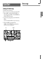
Quick Start .................................................... 7
Explains how to get started using the microKORG (listen to the demos, select
programs, use the arpeggiator and performance functions), and perform basic
editing.
Demo songs ................................................................................. 7
Listening to the demo songs ............................................................................... 7
Synth programs ............................................................................. 8
1. Selecting and playing a program .................................................................... 8
2. Modifying the sound ....................................................................................... 8
Vocoder programs ....................................................................... 10
1. Playing a vocoder program ........................................................................... 10
2. Modifying the sound ..................................................................................... 10
Arpeggiator ................................................................................ 11
Using the arpeggiator ........................................................................................ 11
Editing ........................................................ 12
Explains what you need to know when editing sounds on the microKORG.
Basic editing .............................................................................. 12
Basic editing procedure .................................................................................... 12
Editing each timbre ........................................................................................... 14
Editing a synth program ................................... 15
Explains the functions of the synth program parameters adjusted by edit control
knobs 1–5 for the corresponding setting of the EDIT SELECT 1/2 knobs.
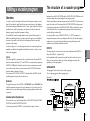
The structure of a synth program ...................................................... 15
Overview ............................................................................................................ 15
Table of Contents
1.
2.
3.
4.
5.
6.
7.
8.
9.
10.
12.
VOICE — SYNTH/VOCODER ............................................................................................ 16
PITCH — SYNTH/VOCODER ............................................................................................ 17
OSC1 (Oscillator 1) — SYNTH/VOCODER .................................................................... 18
OSC2 (Oscillator 2) — SYNTH ...................................................................................... 22
MIXER — SYNTH ............................................................................................................. 23
FILTER — SYNTH ............................................................................................................. 24
FILTER EG — SYNTH ...................................................................................................... 26
AMP — SYNTH ................................................................................................................. 27
AMP EG — SYNTH/VOCODER ......................................................................................... 28
LFO 1, 11. LFO 2 — SYNTH/VOCODER ......................................................................... 29
PATCH 1, 13. PATCH 2, 14. PATCH 3, 15. PATCH 4 — SYNTH ............................ 30
Editing a vocoder program ................................ 31
Explains the function of the vocoder program parameters adjusted by edit control
knobs 1–5 for the corresponding setting of the EDIT SELECT 1/2 knobs.
The structure of a vocoder program .................................................. 31
Overview ............................................................................................................ 31
1. VOICE — SYNTH/VOCODER ............................................................................................... 32
2. PITCH — SYNTH/VOCODER ............................................................................................... 32
3. OSC1 — SYNTH/VOCODER ................................................................................................ 32
4. AUDIO IN 1 — VOCODER .................................................................................................. 33
5. MIXER — VOCODER ........................................................................................................... 34
6. FILTER — VOCODER .......................................................................................................... 35
7. FC MOD — VOCODER ........................................................................................................ 36
8. AMP — VOCODER ............................................................................................................... 37
9. AMP EG — SYNTH/VOCODER ........................................................................................... 37
10. LFO 1, 11. LFO 2 — SYNTH/VOCODER ......................................................................... 37
12. CH LEVEL A, 13. CH LEVEL B — VOCODER .............................................................. 38
14. CH PAN A, 15. CH PAN B — VOCODER ...................................................................... 38
Editing the effects and EQ ................................. 39
Explains the function of the effect and EQ parameters adjusted by edit control
knobs 1–5 for the corresponding setting of the EDIT SELECT 1/2 knobs.
The microKORG's effect structure ..................................................... 39
Overview ............................................................................................................ 39
16. MOD FX — SYNTH/VOCODER ......................................................................................... 40
17. DELAY — SYNTH/VOCODER ............................................................................................ 41
18. EQ — SYNTH/VOCODER ................................................................................................... 42
Editing the arpeggiator .................................... 43
Explains the function of the arpeggiator parameters adjusted by edit control knobs
1–5 for the corresponding setting of the EDIT SELECT 1/2 knobs.
The structure of arpeggiator ........................................................... 43
Overview ............................................................................................................ 43
19. ARPEG. A — SYNTH/VOCODER ...................................................................................... 44
20. ARPEG. B — SYNTH/VOCODER ...................................................................................... 45
Overall settings (GLOBAL) ................................ 46
Explains the function of the Global parameters adjusted by edit control knobs 1–5
for the corresponding setting of the EDIT SELECT 1/2 knobs.
GLOBAL structure ........................................................................ 46
Overview ............................................................................................................ 46
21. GLOBAL .......................................................................................................... 47
v
Table of Contents
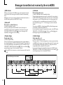
Using the microKORG with other MIDI devices (MIDI).. 48
Explains how to make connections with other MIDI devices, and explains the
function of the MIDI parameters adjusted by edit control knobs 1–5 for the
corresponding setting of the EDIT SELECT 1/2 knobs.
MIDI on the microKORG ................................................................. 48
Overview ............................................................................................................ 48
Connecting MIDI devices/computers ................................................................ 48
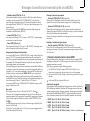
MIDI-related settings after connection ............................................................. 49
22. MIDI ................................................................................................................ 51
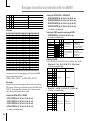
Messages transmitted and received by the microKORG .......................... 52
Saving Data.................................................. 58
Explains how to save a program or Global settings that you edited.
Saving your edited settings ............................................................ 58
Saving a program .............................................................................................. 58
Saving GLOBAL, MIDI, and SHIFT function settings ........................................ 58
SHIFT functions ............................................. 59
Explains functions that use the SHIFT key, such as initializing a program and
restoring the factory settings.
Copying and exchanging timbres — SYNTH .................................................................... 59
Initializing a program ............................................................................................ 59
Initializing CH LEVEL and CH PAN — VOCODER ............................................................ 60
MIDI Filter ............................................................................................................. 60
Assigning control changes .................................................................................... 61
vi
Data dump ............................................................................................................. 62
Restoring the factory settings ............................................................................... 63
Write protect setting ............................................................................................. 63
Other SHIFT key functions .................................................................................... 64
Appendix ..................................................... 65
Provides a troubleshooting checklist, and other information such as the specifications of the microKORG.
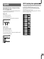
LFO 1/2 and delay time synchronization ............................................................... 65
Troubleshooting .................................................................................................... 66
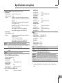
Specifications and options .................................................................................... 67
Index ..................................................................................................................... 68
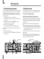
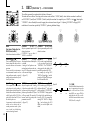
Introduction
Main Features
1. Analog modeling synthesizer
3. 128 built-in programs
The analog modeling system of the microKORG uses DSP technology to
simulate an analog synthesizer. Starting with a variety of different oscillator
algorithms (such as the sawtooth and square waves familiar to users of analog
synthesizers) you can use the various controls located on the front panel to edit
any sound, or to create sounds of your own. All sound parameters are organized
into “sections”. By selecting the appropriate section and turning the appropriate
knob you can edit sounds quickly, easily and intuitively. You can also modify the
sound in realtime as you perform.
The microKORG contains 128 built-in programs. When shipped, the TRANCE–
S.E./HIT banks contain 112 synth programs, and the VOCODER bank contains
16 vocoder programs.
Number of timbres:
Maximum polyphony:
Structure:
maximum 2 (when layer is used)
4 voices
2 oscillators + noise generator: sawtooth wave, square wave,
triangle wave, sine wave, Vox wave, DWGS x 64, Noise,
Audio In (eight types)
PWM function, OSC Sync function, Ring Mod. function, OSC
Sync+Ring Mod. function
Multimode filters: -24 dB/oct LPF, -12 dB/oct LPF, -12 dB/
oct BPF, -12 dB/oct HPF (four types)
Filter EQ, Amp EG, LFO1, LFO2 (LFO: six waveforms, can be
synchronized to the arpeggiator or to external MIDI clock)
2. Vocoder
You can connect a mic to one of the microKORG's AUDIO IN 1 jacks, and use it as
a vocoder – a device that imposes the spectral character of a voice (or other audio
signal) on the sound of an oscillator, producing the impression that the oscillator is
speaking.
The vocoder consists of eight channels (sixteen filters used in pairs). In addition to
simulating the sounds of classic vocoder units, you can change the filter frequency
and adjust the level and pan of each band to create original vocoder sounds.
Maximum polyphony: 4 voices
Structure:
8 channel vocoder, adjustable level/pan for each channel,
Formant Shift function, 1 oscillator + noise generator (eight types)
Filter EG, Amp EG, LFO1, LFO2 (LFO: six waveforms, can be
synchronized to the arpeggiator or to external MIDI clock)
4. Process the waveform of an external input source
The waveform of an external audio source can be input via the AUDIO IN 1 and
2 jacks, and processed in the same way as the internal waveforms.
5. Virtual Patch function
Modulators and controllers such as filter EG, amp EG, LFO 1/2, keyboard
tracking, and wheel can be virtually patched (without using actual patch cables)
to parameters such as pitch, cutoff, and amp. This gives you even more creative
flexibility.
6. Effects to add the finishing touch to your sound
For even greater possibilities, the microKORG provides three types of modulation effect, three types of delay, and an equalizer.
The delay effect can be synchronized with the arpeggiator or an external MIDI
clock, allowing numerous applications in live performance.
7. Step Arpeggiator
The microKORG's arpeggiator lets you produce an arpeggio simply by holding
down a chord.
You can choose from six arpeggio types, and adjust the duration and spacing of
the arpeggiated notes. You can also specify whether a note will be on or off for
each of up to eight steps, letting you create a broad range of modified rhythms
and other effects.
1
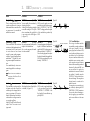
Front and rear panel
○ ○ ○ ○ ○ ○ ○ ○ ○ ○ ○ ○ ○ ○ ○ ○ ○ ○ ○ ○ ○ ○ ○ ○ ○ ○ ○ ○ ○ ○ ○ ○ ○ ○ ○ ○ ○ ○
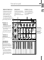
Front panel
Items on the front panel that relate
to the Vocoder are printed in green.
VOLUME knob
Adjusts the volume of the output
from the OUTPUT jacks (L/MONO,
R) and headphone jack.
ARPEGGIATOR ON/OFF key
Switches the arpeggiator on/off.
(When on, the key LED will light.)
ARPEGGIATOR TEMPO LED
Blinks at the tempo of the
arpeggiator performance. If MIDI
CLOCK is set to External and MIDI
Clock data is being received from
the MIDI IN connector, this LED
will blink at that tempo.
OCTAVE SHIFT UP, DOWN keys
Shifts the pitch range of the
keyboard in steps of an octave, over
a range of +/-3 octaves.
PITCH wheel
Controls the pitch.
MOD wheel
Controls the depth of modulation.
2
BANK SELECT dial
Selects the program bank.
BANK SIDE key
Switches between the two sides of each program bank.
(The indicator is dark when side A is selected, and lit
when side B is selected.)
This indicator will blink when the microKORG receives
a MIDI program change, or if the BANK SELECT dial
no longer matches the actual bank.
AUDIO IN 1/2 LEDs
These will light if a signal is being input to the
AUDIO IN jacks. They will light red if an
input overload occurs.
Display
Indicates the current program number,
the value of the selected parameter, or
other various messages.
WRITE key
Saves an edited program or global
setting. (➝p.58)
SHIFT key
By holding down this key and pressing
another key, you can access various
utility functions. (➝p.59)
Also, while this key is lit, it will
function as an EXIT key to exit the
current state and return to normal
operation.
PROGRAM NUMBER
1, 2, 3, 4, 5, 6, 7, 8 keys
Select program numbers (the LED of
the selected key will light).
You can also use these keys to turn each
of the eight steps of the arpeggio
on/off, adding variety to an
arpeggiated performance. (➝p.11)
In addition, you can hold down the
SHIFT key and press one of these keys
to access various utility functions.
(SHIFT function)
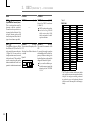
Front and rear panel
TIMBRE SELECT/FORMANT HOLD key
If a Synth program using "layer" is selected,
this key allows you to chose which timbre
will be edited or sounded, or lets you edit
both timbres simultaneously (Sync).
If a Vocoder program is selected, this key
switches Formant Hold on, letting you hold
the tone currently produced by the vocoder
without continuing to speak into the mic.
TIMBRE SELECT 1 LED,
TIMBRE SELECT 2 LED
If a Synth program using Layer is selected,
the LED(s) will light to indicate which
timbre(s) will be edited. If a timbre is being
soloed, its LED will blink.
If a Vocoder program is selected, the 1 LED
will light if the formants are being held.
ORIGINAL VALUE LED
This will light if the value of the parameter
currently being edited matches the value that is
stored in the program. (➝p.13)
(This LED does not function for Performance
Edit.)
EDIT CONTROLS 1, 2, 3, 4, 5 knobs
These knobs edit the Performance Edit
parameters or the parameters of the section
selected by the EDIT SELECT 1 and 2
knobs. (➝p.8, 9, 10)
Vocoder parameters
These are the parameters
for a Vocoder program.
Synth parameters
These are the parameters
for a Synth program.
EDIT SELECT 1 dial,
EDIT SELECT 2 dial
These dials select the section to edit.
(➝p.12)
SYNTH/VOCODER 1 LED,
SYNTH/VOCODER 2 LED
These indicate whether the selected
program is a Synth or a Vocoder program.
If both the SYNTH/VOCODER 1 and 2
LEDs are lit, the Performance Edit function
is enabled.
If only one LED is lit, the EDIT SELECT
knob corresponding to the lit LED will be
the object of your editing. If the object of
editing has not been finalized, the LED will
blink.
3
Front and rear panel
○ ○ ○ ○ ○ ○ ○ ○ ○ ○ ○ ○ ○ ○ ○ ○ ○ ○ ○ ○ ○ ○ ○ ○ ○ ○ ○ ○ ○ ○ ○ ○ ○ ○ ○ ○ ○ ○
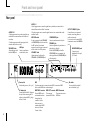
Rear panel
AUDIO IN 2
A Synth program can use an audio signal from an
external device connected here as the oscillator 1
waveform.
A Vocoder program uses this input signal as the
external carrier for the vocoder.
VOLUME 2 knob
Adjusts the input level
from the LINE jack.
4
LINE jack
Connect a synthesizer
or audio device here.
AUDIO IN 1
A Synth program can use an audio signal from a synthesizer or external device
connected here as the oscillator 1 waveform.
A Vocoder program can use an audio signal from a mic etc. connected here as the
modulator audio.
MIC/LINE switch
If a mic is connected to the DYNAMIC
or CONDENSER jack, set this switch to
the MIC position. If an external
sequencer or audio device is connected,
set this switch to the LINE position.
VOLUME 1 knob
Adjusts the input level from the
DYNAMIC or CONDENSER jack.
CONDENSER jack
Connect a condenser mic to this jack.
DYNAMIC jack
Connect a dynamic mic, synthesizer, or
audio device to this jack.
If both the DYNAMIC jack and the
CONDENSER jack are connected, the
audio signal from the CONDENSER jack
will take priority.
Power switch
Switches the power on/off. (➝p.6)
MIDI
Use these connectors to connect the microKORG to an external MIDI
device so that MIDI data can be exchanged.
AC adaptor jack
Connect the included AC adaptor to
this jack. After connecting the AC
adaptor to the microKORG, plug it
into an AC outlet.
MIDI THRU connector
Received MIDI data is
re-transmitted without
change from this
connector. Use this
when you want to
connect multiple MIDI
devices to the same
"stream" of data.
MIDI OUT connector MIDI IN connector
This connector
This connector receives
transmits MIDI data. MIDI data.
OUTPUT L/MONO, R jacks
Connect these to your powered
monitors, stereo amp, mixer, or
multi-track recorder.
If you want to use the microKORG
in monaural, connect the L/MONO
jack.
HEADPHONES jacks
Connect a pair of
headphones to this jack
(1/4" stereo).
Mic holder
You can attach the included
mic to this holder (➝p.5).
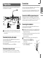
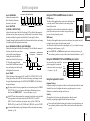
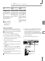
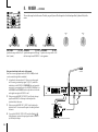
Connections
Preparations
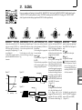
The diagram below shows basic connections for the microKORG. Make substitutions as appropriate for your equipment.
want to use an external sequencer, rhythm machine, or audio source as the carrier
of the vocoder, connect that device to AUDIO IN 2 (➝p.34).
If you want to process the waveform of a synthesizer or sampler, connect a mic or
the output jack of your external device to the AUDIO IN 1 and 2 jacks (➝p.21).
Included mic
○ ○ ○ ○ ○ ○ ○ ○ ○ ○ ○ ○ ○ ○ ○ ○ ○ ○ ○ ○ ○ ○ ○ ○ ○ ○ ○ ○ ○ ○ ○ ○ ○ ○ ○ ○ ○ ○
Connections to MIDI equipment/computers
The keyboard, and controllers etc. of the microKORG can be used to control an
external MIDI tone generator. Conversely, another MIDI keyboard or sequencer can
control the tone generator of the microKORG to produce sound. (➝p.48)
Phones
MIDI OUT
MIDI IN
AC adapter (included)
Connect to an AC outlet
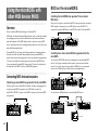
A mic for use with the vocoder is included with the microKORG. Here's how to
attach the included mic to the microKORG.
TAP
1
2
3
4
5
7
8
9
10
11
12
13
14
○ ○ ○ ○ ○ ○ ○ ○ ○ ○ ○ ○ ○ ○ ○ ○ ○ ○ ○ ○ ○ ○ ○ ○ ○ ○ ○ ○ ○ ○ ○ ○ ○ ○ ○ ○ ○ ○
Connecting the included mic
EM-1
15
16
MIDI keyboard, tone generator module, rhythm machine etc.
Powered monitors, etc.
Be sure to turn off the power of all devices before making connections. Failing
to take this precaution may cause your speaker system to be damaged, or may
cause malfunctions.
○ ○ ○ ○ ○ ○ ○ ○ ○ ○ ○ ○ ○ ○ ○ ○ ○ ○ ○ ○ ○ ○ ○ ○ ○ ○ ○ ○ ○ ○ ○ ○ ○ ○ ○ ○ ○ ○
Connections from the audio outputs
Connect the microKORG's OUTPUT L/MONO and R jacks to the input jacks of
your mixer or powered monitor system.
In order to take full advantage of the potential of the microKORG, we recommend
that you use stereo outputs.
If you are making monaural connections, use the L/MONO jack.
Do not apply excessive force to the neck of the mic, or repeatedly bend it back
and forth any more than necessary. Doing so may cause malfunctions such as
breakage of the internal wiring.
1 Grasp the base of the included mic, align the protrusion of the mic with the slit
of the mic holder, and push it into the holder.
Do not use excessive force.
When removing the included mic, grasp it by the base and pull it out.
2 Turn the rear panel AUDIO IN VOLUME 1 knob
Neck
to the MIN position, and set the MIC/LINE switch
to the MIC position.
3 Connect the plug of the included mic to the
Protrusion
Mic base
AUDIO IN 1 CONDENSER jack.
○ ○ ○ ○ ○ ○ ○ ○ ○ ○ ○ ○ ○ ○ ○ ○ ○ ○ ○ ○ ○ ○ ○ ○ ○ ○ ○ ○ ○ ○ ○ ○ ○ ○ ○ ○ ○ ○
Connections to the audio inputs
Slit
If you want to use the microKORG as a vocoder, connect a mic or other audio
source to AUDIO IN 1, and use that audio source as the modulator (➝p.10). If you
5
Turning the power on
○ ○ ○ ○ ○ ○ ○ ○ ○ ○ ○ ○ ○ ○ ○ ○ ○ ○ ○ ○ ○ ○ ○ ○ ○ ○ ○ ○ ○ ○ ○ ○ ○ ○ ○ ○ ○ ○
○ ○ ○ ○ ○ ○ ○ ○ ○ ○ ○ ○ ○ ○ ○ ○ ○ ○ ○ ○ ○ ○ ○ ○ ○ ○ ○ ○ ○ ○ ○ ○ ○ ○ ○ ○ ○ ○
1. The power supply
2. Turning the power on
Before you connect the power supply, make sure that the power switch is turned off
(i.e., in the outward position).
Connecting the AC adaptor
Firmly insert the plug of the included AC adaptor into the jack. Then connect the
AC adaptor to an AC outlet.
Never use any AC adaptor other than the included one.
Inserting/exchanging batteries
The microKORG can also be operated on batteries.
Batteries are not included. You will need to purchase them
separately.
Before you turn on the microKORG’s power, you should lower the level of your
monitor system or other connected output device.
1 Turn the microKORG's VOLUME knob all the way toward the left.
2 Press the power switch to turn on the power.
The display will indicate the program number.
3 Turn the microKORG's VOLUME knob toward the right to an appropriate
position.
4 Adjust the volume of your external output device.
1, 3
2
1 Make sure that the power switch on the microKORG is turned off.
Then open the battery cover located on the bottom of the case.
2 Insert six AA alkaline batteries.
Be careful to observe the correct polarity of the batteries.
3 Close the battery cover.
Low battery display “
”
When the batteries run low, the display will indicate "
," and the "." at the far
right will begin blinking. If you continue using the microKORG, the Protect setting
will be turned on automatically, and you will be unable to edit program or global
settings. We recommend that you install new batteries or switch to the AC adaptor
as soon as possible. If this state occurs while you are editing, and you want to save
your settings, connect the AC adaptor and execute the Write operation.
You can cancel the "
" display by pressing the SHIFT key.
Batteries that have become unusable should be removed from the microKORG
as soon as possible. Leaving such batteries installed may cause malfunctions
(due to battery leakage, etc.). You should also remove the batteries if you will
not be using the microKORG for an extended period of time.
6
○ ○ ○ ○ ○ ○ ○ ○ ○ ○ ○ ○ ○ ○ ○ ○ ○ ○ ○ ○ ○ ○ ○ ○ ○ ○ ○ ○ ○ ○ ○ ○ ○ ○ ○ ○ ○ ○
3. Turning the power off
After saving any necessary data (such as a program you have edited) turn the
power off using the reverse order of the power-on procedure.
Never turn the power off while data is being saved (i.e., while Write is executing). Doing so may damage the internal data.
Demo songs
Quick Start
○ ○ ○ ○ ○ ○ ○ ○ ○ ○ ○ ○ ○ ○ ○ ○ ○ ○ ○ ○ ○ ○ ○ ○ ○ ○ ○ ○ ○ ○ ○ ○ ○ ○ ○ ○ ○ ○
Listening to the demo songs
The microKORG contains several demo songs.
Here's how to listen to the demo songs and hear the sounds of the microKORG.
1 Hold down the SHIFT key and press the ARPEGGIATOR ON/OFF key.
The demo will begin playing. The SHIFT , OCTAVE SHIFT DOWN, UP , and
PROGRAM NUMBER key LEDs will light.
2 To switch the demo song during playback, press the OCTAVE SHIFT UP or
DOWN key.
You can also use the PROGRAM NUMBER 1 –8 keys to select a demo song.
3 When you press the SHIFT key, demo playback will stop.
The SHIFT , OCTAVE SHIFT DOWNand UP key will go dark, and the
microKORG will return to normal playing mode.
1
2
1, 3
2
7
Synth programs
○ ○ ○ ○ ○ ○ ○ ○ ○ ○ ○ ○ ○ ○ ○ ○ ○ ○ ○ ○ ○ ○ ○ ○ ○ ○ ○ ○ ○ ○ ○ ○ ○ ○ ○ ○ ○ ○
○ ○ ○ ○ ○ ○ ○ ○ ○ ○ ○ ○ ○ ○ ○ ○ ○ ○ ○ ○ ○ ○ ○ ○ ○ ○ ○ ○ ○ ○ ○ ○ ○ ○ ○ ○ ○ ○
1. Selecting and playing a program
2. Modifying the sound
The microKORG contains 128 programs that you can select and play immediately.
Programs are arranged in Banks. Each bank contains two “Sides”, and each side
contains eight programs. To select different programs, use the front panel PROGRAM SELECT knob and PROGRAM NUMBER keys. As an example, here's how
to select program "b.26".
On the microKORG, you can modify the sound to add expression to your performance by turning the edit control knobs 1 –5 , by moving the PITCH or MOD
wheels, or by the way that you play the keyboard.
Try out various ways to modify the selected program.
1 Press the BANK SIDE key to select "b" as the program side.
The BANK SIDE key will light when side B is selected, and will be dark when
side A is selected.
2 Turn the PROGRAM SELECT knob to the TECHNO/HOUSE
position.
The display will indicate "2" as the program bank.
Notice that the SYNTH/VOCODER LED for the SYNTH position is lit.
The program will change at the moment you switch either the Side, Bank, or
Number.
4 Play the keyboard to hear the sound.
5 You can use the OCTAVE SHIFT UP or DOWNkeys to shift the pitch range of
the keyboard. (➝p.9)
5
8
1
3
When both the upper and lower SYNTH/VOCODER LEDs are lit, the Performance
Edit function is active. In this state, the edit control knobs 1 –5 are automatically
assigned to control the parameters listed below. Turn these knobs to control the
sound in realtime.
When using Performance Edit, the display shows the program number.
3 Press the 6 key to select the program number.
2
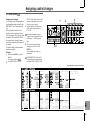
Using the Performance Edit function to modify the sound
Program Side
SYNTH/VOCODER
LED
Program Bank
Program Number
EDIT SELECT 2
Performance Edit will be cancelled if you turn the EDIT SELECT 1 or EDIT
SELECT 2 knob to select a different section, or if you hold down the SHIFT key
and press the BANK SIDE key. To enable the Performance Edit function, press
the PROGRAM NUMBER key that is lit.
When Performance Edit is active, you can edit the sound in the following ways.
Knob 1: CUTOFF
Adjusts the cutoff frequency of the filter. This will affect the brightness of the
sound. Normally, turning the knob toward the left will darken the sound, and
turning it toward the right will brighten the sound.
SYNTH/VOCODER LED
TIMBRE SELECT
PROGRAM NUMBER keys 1–8
Edit control knobs 1–5
Synth programs
Knob 2: RESONANCE
Adjusts the resonance of the
filter. This adds a distinctive
character to the sound.
In the case of a LPF (Low Pass Filter)
Cutoff
Cutoff
Using the PITCH and MOD wheels for control
Cutoff
Cutoff
Low resonance value
High resonance value
Knob 3: EG ATTACK
(FILTER EG + AMP EG ATTACK)
Adjusts the attack time of the filter EG and amp EG. This will affect the amount of
time from note-on (when you press a key) until the attack level is reached. Turning
this knob will adjust the speed at which the filter EG and amp EG will rise.
Normally, turning the knob toward the left will shorten the attack time, and turning
it toward the right will lengthen the attack time.
Knob 4: EG RELEASE (FILTER EG + AMP EG RELEASE)
Adjusts the release time of the filter EG and amp EG. This will affect the amount of
time from note-off (when you release
[3]: Attack Time
[4]: Release Time
Cutoff
a key) until the sound disappears.
+
a: Decay Time
b: Sustain Level
Level
Turning this knob will adjust the
Note off
Note on
release time of the filter EG and amp
EG. Normally, turning the knob
Attack Level
b
toward the left will shorten the release
0
Time
time, and turning it toward the right
[3] a
[4]
will lengthen the release time.
Knob 5: TEMPO
Adjusts the tempo of the arpeggiator, LFO, and DELAY (if "TEMPO SYNC" is ON).
Turning the knob toward the left will slow down the tempo, and turning it toward
the right will speed up the tempo. The ARPEGGIATOR TEMPO LED will blink at
the specified tempo.
If you have selected a Layer program that uses two timbres (one of the TIMBRE
SELECT LEDs is lit), you can choose which timbre will be affected by your
edits. Press the TIMBRE SELECT
key to switch timbres. (➝p.14)
In the EDIT mode, the parameters that are assigned to each knob are also be edited
via the parameters of the section selected by the EDIT SELECT 1 and EDIT
SELECT 2 knobs. For details on each function, refer to p.24 for CUTOFF and
RESONANCE, p.26 and 28 for EG ATTACK and EG RELEASE, or p.44 for TEMPO.
A sound modified modify using Performance Edit can be written into memory
if desired. (➝p.58)
PITCH wheel:
The effect will be applied when you move the wheel away from
or toward yourself. When the wheel is in the center position,
there will be no effect.
Normally this wheel is used as the pitch bender, so that the
pitch will rise when you move the wheel away, and fall when
you move the wheel toward yourself.
0
0
MOD wheel:
The effect will be applied when you move the wheel away from yourself, and will
not apply when you move the wheel toward yourself.
You can use this wheel to control the vibrato depth (➝p.17), or to adjust the tone by
controlling the cutoff frequency (➝p.30).
Since the PITCH and MODwheels can be used as virtual patch sources, you
can use them to produce a variety of effects other than described above. (➝p.30)
Using the OCTAVE SHIFT UP and DOWN keys for control
You can use these keys to shift the
pitches assigned to the keyboard,
in one-octave units over a range of
+/-3 octaves. (➝p.8, 52)
Key operation
Press
DOWN key
Keyboard range
C6–C9
C5–C8
C4–C7
C3–C6
C2–C5
C1–C4
C0–C3
Key LED
UP lit red
UP lit orange
UP lit green
dark
DOWN lit green
DOWN lit orange
DOWN lit red
Key operation
Press UP key
Using the keyboard for control
Keyboard Tracking:
Keyboard tracking uses the position of the note on the keyboard to affect the sound.
Normally, this is used to brighten the sound as you play upward, or to create
differences in volume between high and low notes.
Velocity:
The strength with which you play the keyboard can affect the sound.
Normally, your playing strength will affect the tone and volume.
Since velocity and keyboard tracking can be used as a virtual patch source, you
can use them to produce a variety of effects other than those described above.
(➝p.30)
9
Vocoder programs
○ ○ ○ ○ ○ ○ ○ ○ ○ ○ ○ ○ ○ ○ ○ ○ ○ ○ ○ ○ ○ ○ ○ ○ ○ ○ ○ ○ ○ ○ ○ ○ ○ ○ ○ ○ ○ ○
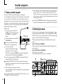
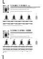
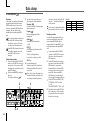
1. Playing a vocoder program
Here's how to connect the included mic and play a vocoder program.
A vocoder applies the spectral character of an externally-input voice (the "modulator") to an oscillator or other sound (the "carrier"), and outputs the result. In the
most popular use of a vocoder, you can speak or sing into a mic and play chords on
the keyboard, to create the impression that an instrument is speaking or singing.
Alternatively, you can create a variety of interesting effects by inputting audio
signals other than a human voice (such as
rhythm sounds).
Included mic
1 On the rear panel, turn the AUDIO IN 1
VOLUME 1 knob to the MIN position, and
set the MIC/LINE
switch to the MIC
position.
2
1 1, 4 2
Connect the included mic to the AUDIO IN
1 CONDENSER jack.
If you use a mic other than the included
one, connect it to the appropriate jack.
3 Select a vocoder program.
Using the procedure described on page 8,
select program "A.84" for this example.
With the factory settings, the VOCODER bank contains vocoder programs.
Notice that the SYNTH/VOCODER LED VOCODER is lit.
6 While vocalizing into the mic and using the keyboard to play vocoder sounds,
you can "freeze" the current tone of the vocoder by pressing the FORMANT
HOLD key. This allows you to continue to play the current vocoder sound, even
when you are not vocalizing. This tone will be remembered when you Write the
vocoder program to memory.
Several of the VOCODER bank programs will sound even if you simply play
the keyboard. These programs were written with FORMANT HOLD turned on.
○ ○ ○ ○ ○ ○ ○ ○ ○ ○ ○ ○ ○ ○ ○ ○ ○ ○ ○ ○ ○ ○ ○ ○ ○ ○ ○ ○ ○ ○ ○ ○ ○ ○ ○ ○ ○ ○
2. Modifying the sound
In the same way as for a synth program, you can modify the sound of a vocoder
program by turning the edit control knobs 1 –5 , by moving the PITCH and MOD
wheels, and by the way that you play the keyboard. As described on the preceding
pages, try out various changes for the selected program.
The following Performance Edit operations work differently than for a synth
program.
Knob 1: CUTOFF, Knob 2: RESONANCE:
These control the carrier by adjusting the band pass filter cutoff frequency of the
carrier. See page 35.
Knob 3: EG ATTACK, Knob 4: EG RELEASE:
Only the amp EG can be controlled.
Also, a vocoder program does not allow you to switch timbres.
4 Vocalize into the mic, and turn the VOLUME 1 knob toward MAX without
4
allowing the AUDIO IN 1 LED to light red.
Raising the AMP "DIRECT LEVEL" value will cause the input sound to be
output directly, so raise the level if you want to hear the input sound while you
make adjustments. (➝p.37)
5 While vocalizing into the mic, play the keyboard.
Try pronouncing different words and changing the chords you play, and listen
to the vocoder effect.
If you cannot hear the effect, try adjusting the AMP "LEVEL" (knob 1 ) (➝p.37)
or MIXER "OSC 1 LEVEL" (knob 1 ) (➝p.34).
10
3
6
SYNTH/VOCODER
LED
Edit control knobs 1–5
Arpeggiator
○ ○ ○ ○ ○ ○ ○ ○ ○ ○ ○ ○ ○ ○ ○ ○ ○ ○ ○ ○ ○ ○ ○ ○ ○ ○ ○ ○ ○ ○ ○ ○ ○ ○ ○ ○ ○ ○
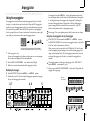
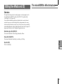
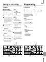
Using the arpeggiator
The arpeggiator is a function that automatically arpeggiates the notes of a chord
you play; i.e., sounds the notes one after the other. The microKORG's arpeggiator
provides six types of arpeggio pattern, and lets you adjust the duration (gate time)
of the notes that are sounded. The microKORG also provides a "step arpeggiator"
that lets you specify the on/off status of each note in the chord for as many as eight
steps, letting you create an even wider range of arpeggio patterns.
For example if you selected ARPEG.A in step 4, the parameters shown in the
lower left diagram (below) will be selected as the knob functions. Turning knob
1 will change the tempo of the arpeggio, and turning knob 3 will change the
duration of the arpeggiated notes. Turning knob 4 will switch the arpeggio
pattern, changing the order in which the notes are sounded (➝p.44). (For
details on each parameter, refer to the appropriate page.)
Refer to page 13 for a note regarding cases in which the value does not change.
Using the step arpeggiator to vary the arpeggio
6 If the EDIT SELECT 2 knob is turned to the ARPEG.A or ARPEG.B
When you play the chord shown above on the keyboard,
the notes will be sounded as shown at the right. (TYPE: UP)
1 Select a program. (➝p.8)
You can use the arpeggiator with either a synth program or a vocoder program,
but let's select synth program b.58 for this explanation.
To change the number of valid steps in the arpeggio, set the EDIT SELECT 2
knob to ARPEG.B and turn knob 4 . (➝p.45)
2 Press the ARPEGGIATOR ON/OFF key to make the key LED light.
3 Hold down a chord on the keyboard, and the arpeggiator will run.
7 When you press the ARPEGGIATOR ON/OFF
Modifying the arpeggio
key (the key LED goes dark), the
arpeggio will stop playing.
4 Turn the EDIT SELECT 2 knob to the ARPEG.A or ARPEG.B position.
5 Turn the edit control 1 –5 knobs to adjust the arpeggiator parameters, changing
the way that the arpeggiator is sounded.
2, 7
position,
the PROGRAM NUMBER 1 –5 keys will act as arpeggiator step keys, and will be
lit (the "on" state) for the number of valid steps.
When you press a step key to make the key LED blink (the "off" state), the note
of the corresponding step will change to a rest, and the resulting arpeggio will
change (see the diagram below). The Step Arpeggiator function lets you switch
each step of the arpeggio on/off in this way to modify the arpeggio that is
sounded.
4, 6
TYPE: UP
LAST STEP: 8
5
6
11
Basic editing
Editing
○ ○ ○ ○ ○ ○ ○ ○ ○ ○ ○ ○ ○ ○ ○ ○ ○ ○ ○ ○ ○ ○ ○ ○ ○ ○ ○ ○ ○ ○ ○ ○ ○ ○ ○ ○ ○ ○
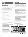
Basic editing procedure
All of the editable parameters are organized into "sections". Each section contains
up to five parameters, which are controlled using the edit control knobs 1 – 5. The
two knobs labelled EDIT SELECT 1 and EDIT SELECT 2 are used to select a
section. Notice the six columns of text under the five knobs. The first column
identifies the name of each section, and the following five columns show the
parameter assigned to each of the knobs above. The text to the left side indicates the
parameters used for a synth program. The text to the right side (in green) indicates
the parameters available for a vocoder program.
On the microKORG there are two basic ways for you to create a sound.
•
Select the program that is closest to the sound you want to create, and edit that
program as necessary to change it as desired
•
Start from an initialized program ("blank slate"), and create the sound from
scratch
Broadly speaking, the procedure is as follows.
1 Select the program that you want to start from. (➝p.8)
If you want to start from scratch, execute the Initialize operation. (➝p.59)
2 Turn the EDIT SELECT 1 or EDIT SELECT 2 knob to select the section that
includes the parameter you want to edit. (The SYNTH/VOCODER LED for the
side you are editing will light.)
Consider how the current program differs from the sound you have in mind,
and select the parameter that you want to edit.
If you are creating the sound from scratch, note that the
EDIT SELECT 1 and EDIT SELECT 2 knobs access
parameter sections in a logical order for creating the
sound. You can turn the dials in sequence to step through
these parameter sections in the appropriate order.
By holding down the SHIFT key and pressing the BANK
SIDE key, you can switch between EDIT SELECT 1 and
EDIT SELECT 2 as the section to edit.
12
4
3 Turn edit control knob 1, 2, 3, 4, or 5 to edit the assigned parameters.
For example if you are editing a synth program and set the EDIT SELECT 1
knob to FILTER, the parameters shown below the diagram at the bottom of this
page will be selected as the function of the five edit control knobs. (The left
parameter of each pair is the synth program parameter, and the right parameter
– in green – is the vocoder program parameter.)
Turning knob 2 will change the cutoff frequency value, affecting the tone.
Turning knob 3 will change the resonance value, adding a distinctive character
to the tone. (➝p.24)
Go ahead and try editing the AMP EG parameters "ATTACK" and "DECAY"
(➝p.28), the PITCH parameter "PORTAMENTO" (➝p.17), or the MOD FX
(➝p.40) or DELAY (➝p.41) parameters to hear the result. (For details on each
parameter, refer to the appropriate page.)
4 If you want to make precise adjustments to a value, hold down the SHIFT key
and press the OCTAVE SHIFT UP or DOWN key (UP, DOWN, and SHIFT keys
will light). Now you can use the UP and DOWN octave keys to step through
the values for the selected parameter.
To cancel this function, press the lit SHIFT key.
If you press the UP and DOWN keys simultaneously, that parameter will return
to the value it had when you selected it.
5 Repeat steps 2–4 as necessary to create the desired sound.
6 Write the program into memory. (➝p.58)
BANK SIDE
4
2
SYNTH/VOCODER LED
ORIGINAL VALUE
3
Basic editing
If you select another program or turn the power off before you write, your edits
will be lost.
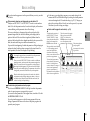
If the parameter value does not change when you turn knobs 1–5
When you use EDIT SELECT 1 or EDIT SELECT 2 to select a section and turn
knobs 1–5 to edit the parameter values, the value in the display will sometimes
continue blinking, and the parameter value will not change.
This occurs when there is a discrepancy between the actual value of the
parameter being edited (the value that is blinking in the display) and the
position of the knob. If the actual value is significantly different from the
position of the knob, and the value changed immediately when you moved the
knob, the sound would change in a sudden and unnatural way.
To prevent this from happening, the knob and parameter will begin changing in
tandem only when the knob position corresponds to the actual value of the
edited parameter (the value in the display will stop blinking).
For example, suppose that you turn knob 1 to edit a parameter,
so that the knob is in the position shown at left.
Then you use the EDIT SELECT 1 knob to switch to a different
parameter section, and want to edit the parameter assigned to
knob 1. The actual value of this parameter is at the position of
the triangle in the diagram at left. (The actual value will blink
when you turn the knob slightly.) The parameter value will not
change until you turn the knob all the way to that position.
When the knob reaches the position of the actual value, the knob
and parameter value will begin changing in tandem, so that you
can edit the value. (When the knob reaches the actual value, the
value in the display will stop blinking.)
In the same way as when editing a program, you can make settings for the
entire microKORG or MIDI-related settings by selecting the desired parameter
section and turning knobs 1–5 to make the settings (➝p.47, 51). Changes you
make to these settings will also be lost if you turn the power off, so you must
Write them if you want to keep your changes.
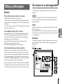
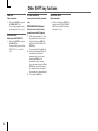
How to read the pages for each section (➝p.16–)
This indicates the position of
the EDIT SELECT 1/2 knob.
The EDIT SELECT 1/2 knob
selects the section that will be
edited. In this example, the
FILTER section is selected.
These are the edit control knobs
1—5. The markings printed
around each knob are the
values that will be selected
when you turn that knob. These
positions are approximate.
This is the name of the section.
When you have set the EDIT
SELECT 1 or 2 knob to the
FILTER position and would like
to see an explanation of the
parameters, refer to this page. This section applies to
synth programs.
A summary of this section
is given here.
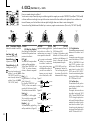
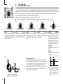
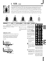
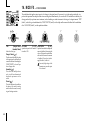
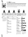
6. FILTER
— SYNTH
The filter removes unwanted frequency regions of the sound produced by the oscillator. It determines the tone by allowing only the desired
portion of the sound to pass. "TYPE" (knob 1) selects the type of filter (i.e., the way in which it will cut the frequency). "CUTOFF" (knob 2) sets
the frequency at which the cut will occur. Normally, turning this knob toward the right will brighten the sound, and turning it toward the left
will darken the sound. "RESONANCE" (knob 3) emphasizes the frequency region near the cutoff frequency, adding a distinctive character to
the sound. Other parameters in this section let you specify the depth of the modulation applied by the filter EG, and the way in which keyboard
tracking will affect the cutoff frequency.
This area lists the parameters
that are edited by edit control
knobs 1—5 when the above
section is selected. The range of
values for each parameter is
given in square brackets [ ].
Explanations of each parameter
and its values are given below.
TYPE
[-24dB LPF, -12dB LPF,
-12dB BPF, -12dB HPF]
Selects the type of filter
24dB LPF (
):
The -24 dB LPF (-24 dB/octave Low
Pass Filter) is the most common
type of filter; it passes the frequencies that are below the cutoff frequency, and cuts the frequencies
that are above (➝Figure 6-1). Lowering the cutoff frequency will
make the tone darker and more
mellow.
-12dB LPF (
):
The -12 dB LPF (-12 dB/octave Low
Pass Filter) has a more gentle slope
than the -24 dB LPF, producing a
more natural-sounding effect.
(➝"-24 dB LPF")(➝Figure 6-1)
CUTOFF
[0...127]
Sets the cutoff frequency.
Increasing this value will raise the
cutoff frequency.
"CUTOFF" can be varied by
time-variant change produced
by Filter EG, by keyboard playing dynamics (velocity), and by
note location (keyboard tracking).
If the "CUTOFF" value is lowered, the volume may be extremely low, or you may hear no
sound at all.
RESONANCE
[0...127]
Sets the resonance of the filter.
This will emphasize the overtones
near the cutoff frequency specified
by "Cutoff," adding a distinctive
character to the sound. Increasing
Figure
6-4 the effect.
this value will
increase
(➝Figure 6-4)
Since movement of the "CUTOFF"
knob will affect the overtones that
are boosted by resonance, it is best
to adjust "CUTOFF" and "RESONANCE" in conjunction with each
other.
The effect of resonance
LPF
Figure 6-1
LPF (Low Pass Filter)
HPF
-12dB/oct
-24dB/oct
BPF
Frequency
Cutoff
Low resonance value
FILTER EG INT
[-63...63]
This specifies how time-variant
modulation from the Filter EG will
be applied to the cutoff frequency
(➝Figure 6-5). The cutoff frequency
will change over time according to
the Filter EG settings, modifying
the tone. For example, you can use
this to create a sound that gradually begins to brighten when you
press the key, and then gradually
becomes darker.
This INT (Intensity) parameter
specifies the depth (sensitivity) to
which the Filter EG will affect the
cutoff frequency.
With a setting of 0, the Filter EG will
not affect the cutoff frequency. Increasingly positive (+) settings will
allow the Filter EG to have a correspondingly greater effect on the
cutoff frequency. (➝Figure 6-6)
Increasingly negative (-) settings
will allow a correspondingly
greater effect in the opposite direction. (➝Figure 6-7)
FILTER KEY TRACK
[-63...63]
This specifies how keyboard tracking (the keyboard location that you
play) will affect the cutoff frequency.
For example if the sound played by
the C4 key has the desired tone but
higher notes no longer have resonance or are too mellow-sounding,
you can adjust keyboard tracking to
make compensations so that the
cutoff frequency will rise for higher
notes.
With positive (+) settings, the cutoff frequency will rise as you play
upward from the C4 note, and fall
as you play downward. With negative (-) settings, the cutoff frequency
will fall as you play upward from
the C4 note, and rise as you play
downward.
With a setting of +48, the change
in cutoff frequency will be proportionate to the change in
pitch. With a setting of 0, keyboard tracking will not affect the
cutoff frequency.
High resonance value
24
To return to the original parameter values of a program
The edit control ORIGINAL VALUE LED will light to indicate the parameter
values of a preset program or a program that you saved.
If you want to return parameters to their original values, turn knobs 1–5 so that
the ORIGINAL VALUE LED is lit.
If you select another program or re-select the same program while you are
editing, all parameters will return to the values of the preset program or the
previously-saved program.
13
Basic editing
○ ○ ○ ○ ○ ○ ○ ○ ○ ○ ○ ○ ○ ○ ○ ○ ○ ○ ○ ○ ○ ○ ○ ○ ○ ○ ○ ○ ○ ○ ○ ○ ○ ○ ○ ○ ○ ○
Editing each timbre
Synth programs can have up to two timbres.
A timbre consists of the parameters of EDIT SELECT 1 VOICE (except for
"SYNTH/VOCODER" and "SINGLE/LAYER") through LFO2 sections, and the
parameters of EDIT SELECT 2 PATCH 1–4 sections.
The VOICE section parameters "SYNTH/VOCODER" and "SINGLE/LAYER"
apply to the entire program.
Using both timbres (Layer)
Listening to only one timbre (Solo)
For a program that uses both timbres, you can use the Solo function to hear just one
timbre. This is convenient when you want to hear just one timbre while you edit.
1 Hold down the SHIFT key and press the TIMBRE SELECT key.
The TIMBRE SELECT LED for the timbre selected for editing will start blinking,
and only that timbre will sound.
2 If you want to hear only the other timbre, once again hold down the SHIFT key
and press the TIMBRE SELECT key.
The TIMBRE SELECT LED for the other timbre will start blinking, and only that
timbre will sound. The timbre selected for editing will also change at this time.
❍ Set the EDIT SELECT 1 knob to VOICE, and turn knob 2 to select
).
LAYER (
3 To cancel the Solo function, press the TIMBRE SELECT key.
Selecting the timbre to edit
Exchanging and copying the settings of the timbres
(SHIFT function)
If you are editing a program that uses both timbres, here's how to select the timbre
to edit.
❍ Press the EDIT SELECT TIMBRE SELECT key to select the timbre that you
want to edit. (The corresponding TIMBRE SELECT LED will light.)
Your editing will affect the selected timbre.
The Solo state cannot be memorized.
You can exchange the settings of the two timbres, or copy the timbre settings from
another program. (➝p.59)
You can also edit both timbres simultaneously (Edit Sync).
1 Press and hold the TIMBRE SELECT key for at least two seconds.
Both TIMBRE SELECT LEDs will light, and editing will be synchronized for the
two timbres. The display will indicate the value for timbre 1. The value of
timbre 1 will also be used as the value at which editing begins.
2 To cancel edit sync, press the TIMBRE SELECT key.
Edit sync will be cancelled, and timbre 1 will be the object of
editing.
You can use the Solo function even while editing is
synchronized.
The state of the edit sync function is not saved.
14
SHIFT
TIMBRE SELECT
Editing a synth program
○ ○ ○ ○ ○ ○ ○ ○ ○ ○ ○ ○ ○ ○ ○ ○ ○ ○ ○ ○ ○ ○ ○ ○ ○ ○ ○ ○ ○ ○ ○ ○ ○ ○ ○ ○ ○ ○
The structure of a synth program
Overview
As shown in figure 0-1, a synth program consists of timbres 1/2, effects, and the
arpeggiator.
The three attributes of sound: pitch, tone, and volume
TIMBRE 1/2
Sound has three basic attributes; pitch, tone, and volume.
To control these attributes, the microKORG analog modeling synthesizer provides
"oscillator," "filter," and "amp (amplifier)" sections, just as on the analog synthesizers of the past.
The "oscillator" settings vary the pitch, the "filter" settings modify the tone, and the
"amp" settings modify the volume.
Each timbre consists of OSC, FILTER, AMP, EG, LFO, and Virtual Patch blocks. You
can create more complex programs by using two timbres together in one program
using the Layer feature.
The microKORG's "oscillator," "filter," and "amp"
On the microKORG, the OSC1, OSC2, and PITCH sections control the "oscillator".
The PITCH section specifies the pitch of the waveform that is the basis of the
sound, and the OSC1 and OSC2 sections select the waveforms. The waveforms
generated here are mixed by the MIXER section.
The microKORG's FILTER section modifies the tone. Then the AMP section
modifies the volume and outputs the final sound.
These three sections determine the basic sound of the program.
EG, LFO, keyboard tracking, virtual patch, controllers
In addition to the sections described above, the microKORG provides ways in
which the sound can be varied according to time, key range, or various types of
performance expression. These are controlled by modulators and controllers such
as EG (envelope generator), LFO (Low Frequency Oscillator), keyboard tracking,
Virtual Patch, and the PITCH and MOD wheels. You can use these modulators and
controllers to apply change to the basic sound of the program.
Figure 0-1 (at right) shows the structure of a synthesizer sound on the microKORG.
Look at TIMBRE 1, and notice how the signal flows in the order of OSC ➝ FILTER
➝ AMP. Also notice how modulators such as EG and LFO can affect these blocks.
EFFECTS
The output of timbres 1/2 is sent to the modulation effect (MOD FX) ➝ delay effect
(DELAY) ➝ equalizer (EQ).
For the modulation effect you can choose from three types of effect such as chorus.
For the delay, you can choose from three types of delay such as stereo delay. The EQ
is a two-band equalizer.
ARPEGGIATOR
You can apply the arpeggiator to a timbre. If the program uses two timbres, you can
apply the arpeggiator to either or both timbres. This is a step arpeggiator with six
arpeggio types.
Figure 0-1
(in the case of Layer)
Free Assign
KBD Track
Velocity
Mod. wheel
Pitch bend
15
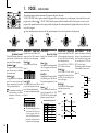
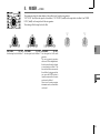
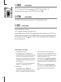
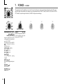
1.
VOICE
— SYNTH/VOCODER
These settings determine the basic character of the program, and how it will sound.
"SYNTH/VOCODER" (knob 1) specifies whether the program will be a synth program or a vocoder program. If you want this to be a synth
program, select Synthesizer (
). "SINGLE/LAYER" (knob 2) specifies whether both timbres will be used (Layer) in the case of a synth
program. Other parameters in this section specify whether the program will sound monophonically/polyphonically/unison, and how the
notes will be triggered.
If you simultaneously press more keys than the specified number of voices, the last-pressed key will take priority.
SYNTH/VOCODER
[Synthesizer, Vocoder]
Switches the currently selected program between a Synthesizer program and a Vocoder program.
SINGLE/LAYER
[Single, Layer] VOICE ASSIGN
Specifies how many timbres the
[Mono, Poly, Unison]
program will use. This cannot be Specifies how the timbre will be
selected for a vocoder program.
sounded.
Single (
):
Mono (
):
Only one timbre will be used.
The timbre will sound monophoniSynthesizer (
):
cally. The program will play only
The program will be a synth pro- Figure 1-1
one note at a time.
gram. You can use two oscillators
Timbre1
to create the sound.
Poly (
):
The program will sound polyphoniVocoder (
):
cally, allowing you to play chords.
The program will be a vocoder proThe maximum polyphony is four
gram. You can use sound input Layer (
):
from a connected mic to produce Two timbres will be used. When voices.
"talking" instrument effects.
you play the keyboard, both tim- Unison (
):
All four voices will sound in uniThe parameters for editing will bres will sound simultaneously.
vary depending on whether You can edit each timbre individually. son at the same pitch. Use "UNISON DETUNE" to specify the pitch
Synthesizer or Vocoder is se- Figure 1-2
difference in steps of one cent.
lected here.
Timbre2
Timbre1
The maximum polyphony is four
voices (four notes). In the case of
a Layer program, these four
voices are divided between timbres 1 and 2, so only two keys can
be played in a layered program.
16
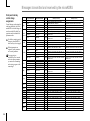
"VOICE ASSIGN" and polyphony for
a Layer program
Timbre 1 Timbre 2
VOICE ASSIGN Mono
Poly
Polyphony 1 voice
3 voices
VOICE ASSIGN Poly
Poly
Polyphony 2 voices
2 voices
VOICE ASSIGN Unison
Mono
Polyphony 2 voices
1 voices
TRIGGER MODE [Single, Multi]
Specifies whether the EG and LFO
will be retriggered when you play
the next key while still holding
down the previous key.
You can edit this if "VOICE ASSIGN" is Mono or Unison.
Single (
):
The EG and LFO will not be
retriggered by the second or subsequent key. Use this setting if you
want to play legato.
Multi (
):
The EG and LFO will be retriggered
each time you press a key.
Figure 1-3
UNISON DETUNE
[0...99]
Specifies the amount of detuning
(in steps of one cent) between the
notes sounded by Unison mode.
You can edit this if "VOICE ASSIGN" is set to Unison.
The detuning method will depend
on the number of unison voices.
Figure 1-4
2 voice
99
0
4 voice
99
0
Note on
EG
Single
Trigger
EG
Multi
Trigger
Note on
Unison
Detune
Unison
Detune
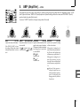
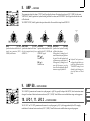
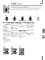
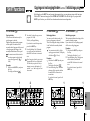
2.
PITCH
— SYNTH/VOCODER
These settings specify the pitch of the oscillator.
Use "TRANSPOSE" (knob 1) and "TUNE" (knob 2) to set the desired pitch. These settings are shared by oscillators 1 and 2. In this section you
can also set the portamento time, and specify how the PITCH and MOD wheels will affect the pitch.
TRANSPOSE
[-24...24] TUNE
[-50...50]
Adjusts the pitch of the oscillator in Adjusts the pitch of the oscillator in
semitone (100 cent) steps.
one-cent steps.
The range is two octaves upward or
downward.
Changes made by the front
panel OCTAVE SHIFT buttons
actually shift the pitches assigned to the keyboard (or keys)
in one-octave steps, and do not
affect the pitch of the oscillator
that is sounding. Nor are such
settings saved by the Write operation. If you wish to change
the pitch of the oscillator itself,
you must use this "TRANSPOSE" setting to specify the
pitch.
PORTAMENTO
[0...127]
Specifies the speed of the
portamento effect (a smooth change
in pitch from one note to the next
note of a different pitch).
With a setting of 0, there will be no
portamento effect. Increasing this
value will cause the pitch change to
occur over a longer time.
BEND RANGE
[-12...12]
Specifies the amount of pitch
change in semitones that will occur
when the pitch wheel is operated.
This value specifies the amount of
change that will occur when you
move the pitch wheel all the way
to the away from you.
VIBRATO INT
[-63...63]
Specifies the depth of vibrato that
will be applied when you move the
MOD (modulation) wheel all the
way away from yourself.
The LFO2 modulates the pitch of
the oscillator, raising and lowering it to create vibrato.
If "VOICE ASSIGN" is set to
Mono or Unison, and if "Trigger"
is set to Single, portamento will
not apply to the first-sounded
note.
17
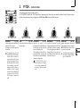
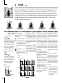
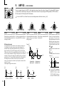
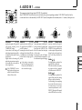
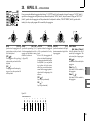
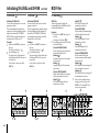
3.
OSC1 (Oscillator 1)
— SYNTH/VOCODER
The oscillator generates the waveform that is the basis of the sound.
The timbre has two oscillators. The settings in this section are for oscillator 1. "WAVE" (knob 1) selects the basic waveform for oscillator 1,
and "CONTROL 1" (knob 2) and "CONTROL 2" (knob 3) modify the waveform. For example if you set "WAVE" to Saw (
), adjusting the
"CONTROL 1" value will modify the sound, changing the waveform as shown in figure 3-1. Adjusting "CONTROL 2" will apply LFO1
modulation to the waveform specified by "CONTROL 1," producing additional change.
18
WAVE
[Saw, Square, Triangle, Sine, Vox,
DWGS, Noise, Audio In]
Selects the waveform for oscillator 1.
CONTROL 1
[0...127/– – –] CONTROL 2
[0...127/1...64]
Adjusts a parameter specific to the Adjusts a parameter specific to the
selected waveform.
selected waveform.
CONTROL 1 has no effect if
"WAVE" is set to DWGS.
Saw Wave (
):
This is a sawtooth wave. This waveform is shaped like the tooth of a
saw, and contains a rich overtone
spectrum.
You can use this to create numerous instrumental sounds such as
string and brass sounds, or typical
analog synth sounds such as synth
bass or synth brass.
CONTROL 1
[0...127]:
Adjusting this value will modify the
waveform.
A setting of 0 will produce a conventional sawtooth wave, and a setting of 127 will produce a sawtooth
wave one octave higher.
(➝Figure 3-1)
CONTROL 2
[0...127]: Figure 3-1
LFO1 is used to apply modulation
to the waveform specified by
"CONTROL 1." The "CONTROL 2"
0
setting specifies the depth of the
modulation produced by LFO1.
For example by setting LFO1
"WAVE" to Triangle (
) and adjusting the LFO speed, you can produce a detune-like effect.
Square Wave (
):
This is a square wave. It has a rectangular shape, and strictly speaking is
actually square only when the top and
bottom of the waveform have the same
width (a "pulse width" of 50%). If the
pulse width is other than 50%, this is
also called a pulse wave.
A square wave is used for woodwind
sounds such as clarinet, and for
wooden percussion sounds. A pulse
wave is used for plucked-string
sounds and reed-type sounds.
CONTROL 1
[0...127]:
Adjusts the pulse width. A setting
of 0 produces a pulse width of 50%
(square wave), and a setting of 127
produces a pulse width of 0% (there
will be no sound). The sound will
become "harder" as you adjust this
parameter toward 0%.
(➝Figure 3-2)
CONTROL 2
[0...127]: Figure 3-2
LFO1 is used to apply PWM (pulse
width modulation)* 3-1 to the pulse
width specified by "CONTROL 1."
The "CONTROL 2" setting specifies
0
the depth of the modulation produced by LFO1. For example by
setting LFO1 "WAVE" to Triangle
(
) and adjusting the LFO
speed, you can add depth to the
sound.
63
63
127
127
*3-1: PWM
Pulse Width Modulation refers to the
use of a separate signal to vary the
pulse width over time. On the
microKORG, you can use PWM to
modify the tone via LFO1, or via Virtual Patch from modulation sources
LFO2, Filter EG, or Amp EG.
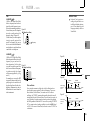
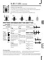
3.
OSC1 (Oscillator 1)
— SYNTH/VOCODER
WAVE
CONTROL 1
CONTROL 2
Triangle Wave (
):
This is a triangle wave, which has
weaker overtones and a stronger
fundamental than a sawtooth wave
or square wave. It is suitable for
mellow bass sounds.
CONTROL 1
[0...127]:
You can modify the waveform by
adjusting this value.
A setting of 0 will produce a triangle
wave, and a setting of 127 will produce a waveform with a pitch that
is one octave and a fifth higher.
(➝Figure 3-3)
CONTROL 2
[0...127]: Figure 3-3
LFO1 is used to apply wave form
modulation to the waveform specified by "CONTROL 1." The "CON0
TROL 2" setting specifies the depth
of the modulation produced by
LFO1.
Sine Wave (
):
This is a sine wave. This waveform
contains only the fundamental, and
no overtones at all. It can be used
to create claves or bass drum
sounds. In some synth programs,
oscillator 2 is used to perform cross
modulation*3-2 (➝Figure 3-4), creating a more complex overtone structure.
Cross modulation by a sine wave
cannot be applied to a vocoder program.
CONTROL 1
[0...127]:
On a synth program, this adjusts the
depth of cross modulation.
On a vocoder program, this modifies the waveform.
CONTROL 2
[0...127]: Figure 3-4
On a synth program, this adjusts the
OSC2
depth of additional modulation
applied by LFO1 to the cross modu- OSC1
lation specified by "CONTROL 1."
On a vocoder program, this adjusts
the depth of modulation applied by
LFO1 to the waveform that you selected by "CONTROL 1."
63
127
X-mod Depth + X-mod Depth Mod
OSC1 Output
Since a sine wave contains no
overtones, the filter will not
modify its tone.
):
CONTROL 1
[0...127]:
This simulates a waveform similar Adjusting this value will modify the
to human vocal cords. Even if the waveform. (➝Figure 3-5)
oscillator pitch is changed, the frequency spectrum will be maintained, which makes this effective
when used for vocal-type sounds or
as a vocoder oscillator.
Select HPF or BPF as the filter, and
adjust "Cutoff" to create a vocaltype sound.
Vox Wave (
CONTROL 2
[0...127]:
LFO1 is used to apply modulation
to the waveform specified by
"CONTROL 1." CONTROL 2 sets
the depth of the modulation applied by LFO1.
Figure 3-5
0
63
127
*3-2: Cross Modulation
This is a type of oscillator modulation available on analog synthesizers
of the past. Normally, a low-frequency signal (such as from an LFO)
is used as the modulation source for
an oscillator, but Cross Modulation
lets you use another oscillator as the
modulation source, creating sounds
with a complex overtone structure
that would not normally be produced
otherwise. On the microKORG, you
can use oscillator 2 to apply cross
modulation if a sine wave is selected
for oscillator 1. Gradually raise the
"CONTROL 1" level, and notice how
the sound changes. This can produce
distorted sounds, or sounds with a
metallic character.
You can produce an even wider variety of effects by adjusting the OSC2
"SEMITONE" or "TUNE" parameters.
You can also achieve interesting results by applying sync modulation
and cross modulation at the same
time.
19
3.
WAVE
CONTROL 1
DWGS (
)
(Digital Waveform Generator System):
CONTROL 1
This is waveform data created by
harmonic additive synthesis.
Choose this when you want to create sounds with a distinctive "digital-synth" character, such as synth
bass, electric piano, bell, or horn. 64
types of waveform are provided.
Noise (
):
This generates white noise. Within
the oscillator, a LPF (Low Pass Filter) is provided to process the noise.
(➝Figure 3-6). You can use this to
create percussion sounds, or sound
effects such as surf. This can also be
used in conjunction with another
timbre to simulate the "breath" component of a wind instrument sound.
20
OSC1 (Oscillator 1)
CONTROL 2
[– – –]:
–––
CONTROL 1
[0...127]:
This sets the cutoff frequency of the
LPF.
Adjusting this will affect the noise
waveform.
Figure 3-6
Resonance
Noise
Genarator
— SYNTH/VOCODER
LPF
Cutoff
CONTROL 2
[1...64]:
Selects the DWGS waveform.
(➝Table 3-1)
DWGS waveform data was first
used in the Korg DW-6000
(which went on sale in 1984),
and has continued to be developed since that time.
CONTROL 2
[0...127]:
This controls the resonance of the
LPF.
If you raise this enough to produce
an identifiable pitch, the cutoff frequency will move according to the
keyboard location you play, and the
change will be heard as a pitch.
If you want the oscillation produced by resonance to match the
reference pitch, set "CONTROL
1" to 24.
Table 3-1
DWGS List
No.
1
2
3
4
5
6
7
8
9
10
11
12
13
14
15
16
17
18
19
20
21
22
23
Name
SynSine1
SynSine2
SynSine3
SynSine4
SynSine5
SynSine6
SynSine7
SynBass1
SynBass2
SynBass3
SynBass4
SynBass5
SynBass6
SynBass7
SynWave1
SynWave2
SynWave3
SynWave4
SynWave5
SynWave6
SynWave7
SynWave8
SynWave9
No.
24
25
26
27
28
29
30
31
32
33
34
35
36
37
38
39
40
41
42
43
44
45
46
Name
5thWave1
5thWave2
5thWave3
Digi1
Digi2
Digi3
Digi4
Digi5
Digi6
Digi7
Digi8
Endless*
E.Piano1
E.Piano2
E.Piano3
E.Piano4
Organ1
Organ2
Organ3
Organ4
Organ5
Organ6
Organ7
No.
47
48
49
50
51
52
53
54
55
56
57
58
59
60
61
62
63
64
Name
Clav1
Clav2
Guitar1
Guitar2
Guitar3
Bass1
Bass2
Bass3
Bass4
Bass5
Bell1
Bell2
Bell3
Bell4
Voice1
Voice2
Voice3
Voice4
*: The 35 Endless waveform simulates an endless
scale, in which notes one octave apart have the identical pitch. You can play an ascending or descending scale as far as you wish, producing the sensation that a scale of the same pitch is continuing infinitely.
3.
WAVE
Audio In (
):
The waveform of the audio signal
input from the AUDIO IN 1 or 2
jacks will be used instead of an oscillator.
This lets you apply filtering to a
drum phrase, or synthesize a vocal
or guitar sound together with oscillator 2.
OSC1 (Oscillator 1)
— SYNTH/VOCODER
CONTROL 1
CONTROL 2
CONTROL 1
[0...127]:
This adjusts the volume balance
between AUDIO IN 1 and AUDIO
IN 2. With a setting of 127 only AUDIO IN 1 will be output. With a setting of 0, only AUDIO IN 2 will be
output.
CONTROL 2
[0...127]:
LFO1 is used to apply modulation
to the volume balance between
AUDIO IN 1 and AUDIO IN 2 that
you set by "CONTROL 1." The
"CONTROL 2" setting sets the
depth of this modulation produced
by LFO1.
This lets you create effects in which
the AUDIO IN 1 and 2 inputs are
alternated.
The parameters of the PITCH
section have no effect on the
waveform that is input from the
AUDIO IN 1 or 2 jacks.
Processing an external input audio signal
You can use the filter, amp, EG, and LFO etc. to process the signal from a external
synthesizer, rhythm machine, or audio device in the same way as an oscillator waveform.
Before you connect an external device, turn off the power of the microKORG and of
any external output devices and power amps.
1
2
3
Turn the rear panel AUDIO IN 2 VOLUME 2 knob to the MIN position.
4
Select a program to initialize, and initialize it.
Connect the output jack of your external device to the AUDIO IN 2 LINE jack.
After making connections, turn the power on in the order of your external device, the
microKORG, and finally your powered monitor speaker system.
In this example, you could connect the microKORG's MIDI OUT to the MIDI IN of
your external MIDI device and set the MIDI channels to match, so that your sound
module or other external MIDI device will produce sound when you play the
keyboard of the microKORG (➝p.49). You can use the microKORG's keyboard to play
the sounds of your external device, and use the EDIT SELECT 1/2 knobs and the edit
control knobs 1–5 to modify the sound.
You can use an external input as the carrier of the vocoder. (➝p.34)
For this example, select any synth program, and initialize the program as described
on page 59.
5
Turn the EDIT SELECT 1 knob to the OSC 1 position, and turn knob 1 ("WAVE") to
select "
" (Audio In).
6
Input an audio signal from your external device, and turn the VOLUME 2 knob
toward MAX as far as possible without allowing the AUDIO IN 2 LED to light red.
7
8
While inputting an audio signal, play the keyboard.
MIDI OUT
MIDI IN
LINE OUT
EM-1
As described in "Basic editing procedure" (➝p.12), edit the FILTER, AMP, EG, LFO,
and effects to modify the sound.
The PITCH-related parameters have no effect on the sound from the AUDIO IN jacks.
TAP
1
2
3
4
5
7
8
9
10
11
12
13
14
15
16
tone generator module, rhythm machine,
or audio device
21
4. OSC2 (Oscillator 2)
— SYNTH
Here you can make settings for oscillator 2.
You can create a variety of sounds by using two oscillators together. For example you can adjust "SEMITONE" (knob 3) and "TUNE (knob 4)
so that one oscillator acts as though it were part of the overtone structure of the other oscillator, set the pitches of the two oscillators to an
interval of harmony, or set both oscillators to the same pitch but slightly detune one of them to create a detuning effect.
You can also use Ring Modulation and Oscillator Sync to create very complex overtone structures. (This is set by "OSC MOD" (knob 2).)
WAVE
[Saw, Square, Triangle] OSC MOD
Selects the waveform for oscillator
[OFF, Ring, Sync, RingSync]
2.
Selects the type of oscillator modulation that will be produced in conSaw Wave (
):
junction with oscillator 1.
A sawtooth wave. (➝p.18)
SEMITONE
[-24...24]
Specifies the detuning (pitch difference) relative to oscillator 1, in
semitone steps over a range of 2
octaves upward or downward.
TUNE
[-63...63]
Specifies the amount of detune for
OSC2 relative to OSC1.
A setting of ±63 produces a pitch
difference of ±2 octaves, and ±48
produces a pitch difference of ±1
If you want to use the sound of
octave. A value near 0 will make
oscillator 2 as a component in
fine adjustments in the pitch.
the oscillator 1 overtone struc-
OFF (
):
The sound will be output without
applying oscillator modulation.
Triangle Wave (
):
ture, try setting it one octave or
You can adjust "SEMITONE" and
A triangle wave. (➝p.19)
a fifth higher than oscillator 1. If
"TUNE" to produce harmony,
you want to use oscillator 2 in
If you do not hear the sound of detune, or harmonic-component
harmony, you can try intervals
oscillator 2, raise the MIXER effects.
such as a third, fourth, or fifth.
"OSC2 LEVEL" (knob 2). If you Ring (
):
want to hear only the sound of Ring modulation * 4-1 will be ap- Figure 4-1
oscillator 2, lower the MIXER plied. (➝Figure 4-1)
OSC2 Wave
OSC2 Output
"OSC 1 LEVEL" (knob 1).
By adjusting "SEMITONE" and
Square Wave (
):
A square wave. (➝p.18)
"TUNE" you can create metallic OSC1 Wave
sounds with little sense of pitch.
This is effective for sound effects. Figure 4-2
OSC2 Wave
Sync (
):
Oscillator sync *4-2 will be applied.
Sync
This is useful for creating synth- OSC1 Wave
lead sounds. (➝Figure 4-2)
Figure 4-3
RingSync (
):
This simultaneously applies Ring OSC2 Wave
and Sync modulation. (➝Figure 4-3)
Sync
OSC1 Wave
22
OSC1 Output
OSC2 Output
OSC1 Output
OSC2 Output
OSC1 Output
If "OSC MOD" is set to Sync,
adjustments in "Semitone" or
"Tune" will change the pitch of
the overtones. The pitch of the
fundamental will not change.
*4-1: Ring Modulation:
This modulation generates a sum and
difference of the oscillator 1 and 2
waveforms.
For example you can select a square
wave for the oscillator, set "TRANSPOSE" to 0, "SEMITONE" to 24, and
adjust "TUNE" to produce a clear
bell-like sound. The effect will be
easier to detect if you lower "OSC 1
LEVEL" and raise "OSC 2 LEVEL."
You can also create interesting effects
by using Virtual Patch to modulate
OSC 2 TUNE from LFO or EG.
*4-2: Oscillator Sync:
This modulation forcibly synchronizes the phase of oscillator 2 to the
phase of oscillator 1.
For example, select sawtooth wave
for oscillator 1 and raise the "OSC 2
LEVEL." Then, edit "SEMITONE" and
"TUNE" to change the pitch, and notice the result. The effect will be more
noticeable if the oscillator 2 pitch is
raised above the oscillator 1 pitch.
You can also produce interesting effects by using Virtual Patch to modulate OSC 2 Tune from LFO or EG.
5.
MIXER
— SYNTH
These parameters adjust the volume balance of the oscillator 1 and 2, and the noise generator.
"OSC 1 LEVEL" (knob 1) sets the output level of oscillator 1, "OSC 2 LEVEL" (knob 2) sets the output level of oscillator 2, and "NOISE
LEVEL" (knob 3) sets the output level of the noise generator.
These settings will be the input level to the filter.
OSC 1 LEVEL
[0...127] OSC 2 LEVEL
[0...127] NOISE LEVEL
[0...127]
Sets the output level of oscillator 1. Sets the output level of oscillator 2. Sets the output level of the noise
generator.
This noise generator generates
white noise. This is independent of
the white noise that can be selected
as a waveform for oscillator 1. This
does not have filter or resonance (as
the oscillator 1 noise generator, but
you can use the FILTER section to
create the same results as the noise
waveform of oscillator 1.
Noise is used to create percussion
instrument sounds, or sound effects
such as surf.
23
6.
FILTER
— SYNTH
The filter controls the tonal character of the sound produced by the oscillator. It determines the tone by allowing only the desired portion of
the sound to pass. "TYPE" (knob 1) selects the type of filter (i.e., the way in which it will cut the frequency). "CUTOFF" (knob 2) sets the
frequency at which the cut will occur. Normally, turning this knob toward the right will brighten the sound, and turning it toward the left
will darken the sound. "RESONANCE" (knob 3) emphasizes the frequency region near the cutoff frequency, adding a distinctive character to
the sound. Other parameters in this section let you specify the depth of the modulation applied by the filter EG, and the way in which
keyboard tracking will affect the cutoff frequency.
TYPE
[-24dB LPF, -12dB LPF,
-12dB BPF, -12dB HPF]
Selects the type of filter
-24dB LPF (
):
The -24 dB LPF (-24 dB/octave Low
Pass Filter) is the most common
type of filter; it passes the frequencies that are below the cutoff frequency, and cuts the frequencies
that are above (➝Figure 6-1). Lowering the cutoff frequency will
make the tone darker and more
mellow.
-12dB LPF (
):
The -12 dB LPF (-12 dB/octave Low
Pass Filter) has a more gentle slope
than the -24 dB LPF, producing a
more natural-sounding effect.
(➝"-24 dB LPF")(➝Figure 6-1)
CUTOFF
[0...127]
Sets the cutoff frequency.
Increasing this value will raise the
cutoff frequency.
"CUTOFF" can be varied by
time-variant change produced
by Filter EG, by keyboard playing dynamics (velocity), and by
note location (keyboard tracking).
RESONANCE
[0...127]
Sets the resonance of the filter.
This will emphasize the overtones
near the cutoff frequency specified
by "CUTOFF," adding a distinctive
character to the sound. Increasing
this value will increase the effect.
(➝Figure 6-4)
Since movement of the "CUTOFF"
knob will affect the overtones that
are boosted by resonance, it is best
If the "CUTOFF" value is set too
to adjust "CUTOFF" and "RESOlow, the volume may be exNANCE" in conjunction with each
tremely low, or you may hear no
other.
sound at all.
Figure 6-4
The effect of resonance
LPF
Figure 6-1
LPF (Low Pass Filter)
HPF
-12dB/oct
-24dB/oct
BPF
Frequency
Cutoff
24
Low resonance value
High resonance value
FILTER EG INT
[-63...63]
This specifies how time-variant
modulation from the Filter EG will
be applied to the cutoff frequency
(➝Figure 6-5). The cutoff frequency
will change over time according to
the Filter EG settings, modifying
the tone. For example, you can use
this to create a sound that gradually begins to brighten when you
press the key, and then gradually
becomes darker.
This INT (Intensity) parameter
specifies the depth (sensitivity) to
which the Filter EG will affect the
cutoff frequency.
With a setting of 0, the Filter EG will
not affect the cutoff frequency. Increasingly positive (+) settings will
allow the Filter EG to have a correspondingly greater effect on the
cutoff frequency. (➝Figure 6-6)
Increasingly negative (-) settings
will allow a correspondingly
greater effect in the opposite direction. (➝Figure 6-7)
FILTER KEY TRACK
[-63...63]
This specifies how keyboard tracking (the keyboard location that you
play) will affect the cutoff frequency.
For example if the sound played by
the C4 key has the desired tone but
higher notes no longer have resonance or are too mellow-sounding,
you can adjust keyboard tracking to
make compensations so that the
cutoff frequency will rise for higher
notes.
With positive (+) settings, the cutoff frequency will rise as you play
upward from the C4 note, and fall
as you play downward. With negative (-) settings, the cutoff frequency
will fall as you play upward from
the C4 note, and rise as you play
downward.
With a setting of +48, the change
in cutoff frequency will be proportionate to the change in
pitch. With a setting of 0, keyboard tracking will not affect the
cutoff frequency.
6.
FILTER
— SYNTH
TYPE
FILTER KEY TRACK
Keyboard Track operates according to the pitch that is controlled by pitch bend, and transpose. It is not affected by pitch
changes produced by vibrato or
Virtual Patch.
Frequency
-12dB HPF (
):
-12dB/oct HPF (High Pass Filter)
allows frequencies above the cutoff
frequency to pass, and cuts the
lower frequencies. Use this when
Figure 6-3
you wish to make the sound thinHPF (High Pass Filter)
ner. However if the cutoff frequency
is raised excessively, the volume
will decrease significantly. (➝Figure 6-3)
For example you can use the HPF
Frequency
to purposely attenuate the low-freCutoff
quency region of a sound that will
be played together with other lowFilter oscillation
frequency instruments, in order to
If you raise the resonance to a high value, it will oscillate (produce a
differentiate that sound from the
sound) at the frequency specified by the cutoff frequency. You can use
other instruments.
filter oscillation ("self-oscillation") as a sound source. If the filter is
oscillating, the "CUTOFF" parameter that normally adjusts the tone will
instead control the pitch of the oscillation. This can be used in a variety of
ways. Whistling is a typical example, and can be produced by adjusting
the ADSR parameters of the filter EG. You can also try setting "FILTER EG
INT" to a negative value. Another possibility is to select the MOD wheel
or LFO 1/2 as a source in Virtual Patch, and use it to control "CUTOFF" as
a destination.
Figure 6-5
Note off
Note on
Sustain Level
Cutoff
-12dB BPF (
):
-12dB/oct BPF (Band Pass Filter)
allows a frequency band in the region of the cutoff frequency to pass,
and cuts the remaining frequencies. Figure 6-2
It is used when you wish to emphaBPF (Band Pass Filter)
size only a specific portion of the
frequency range.(➝Figure 6-2)
Use this when you want to emphasize just a specific region of the
sound. For example, you can use
Cutoff
this to create a bandwidth-limited
sound similar to sound heard from
a small radio or a telephone.
Attack
Time
Decay
Time
Release Time
Time
Figure 6-6
Cutoff
Int=+32
Note on
Note off
Int=+63
Note on Note off
Cutoff frequency
specified by
“Cutoff”
Int=0
Time
Figure 6-7
Cutoff frequency
specified by
“Cutoff”
Cutoff
Int=–32
Int=–63
Int=0
Note off
Note on
Note on
Note off
Time
25
7.
FILTER EG
— SYNTH
Here you can make settings for the filter EG, which applies time-variant change to the tone (➝Figure 7-1). Make these settings to specify the
"shape" of the EG, and use the FILTER parameter "FILTER EG INT" to specify the amount of effect that the EG will have (➝p.24). By making
FILTER EG settings, you can make the tone change as time passes. Create the desired tonal curve by adjusting the ADSR parameters;
ATTACK (knob 1), DECAY (knob 2), SUSTAIN (knob 3), RELEASE (knob 4).
For details on how an EG (Envelope Generator) works, refer to AMP EG (➝p.28).
You can use the FILTER EG as a Virtual Patch source modulate a parameter other than the filter cutoff frequency. (➝p.30)
ATTACK
[0...127]
Specifies the time from note-on
(when the key is pressed) until the
attack level (maximum value of the
envelope) is reached.
DECAY
[0...127]
Specifies the time from when the attack level is reached until the sustain level (SUSTAIN) is reached.
SUSTAIN
[0...127]
Specifies the cutoff frequency that
will be maintained after the decay
time has elapsed, until you release
the key.
RELEASE
[0...127]
Specifies the time from note-off
(when the key is released) until the
level reaches 0.
EG RESET
[OFF, ON]
Specifies whether or not the EG will
be reset for the second and subsequent note-on. If a new note is
played before the previous note has
finished its release stage, the envelope can either start over from zero,
or continue from the current value.
OFF (
):
The note will start from the current
EG level.
ON (
):
The second note-on will start from
a level of 0.
Note on
Figure 7-1
Cutoff
Note off
Note on
Attack Level
[3]
Time
0
[1] [2]
[1]: Attack Time
[2]: Decay Time
26
[4]
[3]: Sustain Level
[4]: Release Time
Filter EG and Amplifier EG
When the Filter EG changes the cutoff frequency, the tone will change.
However depending on the volume changes produced by the Amplifier
EG, this can be heard in different ways. For example by changing the
speed at which the tone and volume begin (attack) or decay, you can
significantly vary the character of the tonal change. It is a good idea to
adjust the changes of both the Filter EG (tone) and the Amplifier EG
(volume) as you proceed with editing.
Note off
Note on (Retrigger)
OFF
ON
The "EG RESET" parameter is
only available if "VOICE ASSIGN" is set to Poly, or if "VOICE
ASSIGN" is set to Mono or Unison and "TRIGGER" is set to
Multi.
8.
AMP (Amplifier)
— SYNTH
These parameters specify the volume. The sound that is created by passing through the oscillator and filter is amplified by the amp. "LEVEL"
(knob 1) adjusts the volume. "KBD TRACK" (knob 4) adjusts how keyboard tracking will affect the volume, and "DISTORTION" (knob 3)
specifies whether the sound will be distorted.
You can use "PANPOT" (knob 2) to set the pan (stereo position of the sound).
LEVEL
[0...127]
Adjusts the volume of the timbre.
PANPOT
[L63...Center...R63] DISTORTION
[OFF, ON]
Adjusts the location of the sound in Specifies whether distortion will be
applied to the output of the timbre.
If the "SINGLE/LAYER" is Layer, the stereo field.
this setting will adjust the volume L63(
) is far left, Center (
) The degree of distortion is adjusted
balance between timbre 1 and tim- is center, and R63 (
) is far right. by the output level of each oscillator in the MIXER.
bre 2.
OFF (
):
Distortion is off.
ON (
):
Distortion is on.
KBD TRACK
[-63...63]
Specifies how keyboard tracking
will affect the volume.
With positive (+) settings, the volume will increase as you play above
the C4 note on the keyboard, and
will decrease as you play below C4.
With negative (-) settings, the volume will decrease as you play
above the C4 note on the keyboard,
and will increase as you play below
C4.
Keyboard Track operates according to the pitch that is controlled by pitch bend, and transpose. It is not affected by pitch
changes produced by vibrato or
Virtual Patch.
27
9.
AMP EG
— SYNTH/VOCODER
Here you can make settings for the AMP EG, which applies time-variant change to the volume (➝Figure 9-1). By making AMP EG settings,
you can make the volume change as time passes. Create the desired volume curve by adjusting the ADSR parameters; ATTACK (knob 1),
DECAY (knob 2), SUSTAIN (knob 3), RELEASE (knob 4).
You can use AMP EG as a Virtual Patch source to modulate parameters other than volume. (➝p.30)
ATTACK
[0...127]
Specifies the time from note-on
(when the key is pressed) until the
attack level (maximum value of the
envelope) is reached.
DECAY
[0...127]
Specifies the time from when the attack level is reached until the sustain level (SUSTAIN) is reached.
SUSTAIN
[0...127]
Specifies the volume that will be
maintained after the decay time has
elapsed, as long as you continue
holding the key.
EG (Envelope Generator)
To a significant extent, each sound has its own distinctive volume curve.
For example when you play a note on a piano, the note begins at the
maximum volume, and gradually diminishes. When you release your
finger from the key, the sound will disappear quickly with a brief decay.
Volume curves such as this are an important aspect of how we identify the
sound of a specific instrument. This type of change also occurs in the tone
and pitch, as well as in the volume. On a synthesizer, this type of change is
produced by an EG. The microKORG has dedicated EGs for the filter and
for the amp. However since these EGs can be used as Virtual Patch
sources, you are also free to use them to vary the pitch or numerous other
aspects of the sound.
Some example settings are shown below.
Figure 9-1
Piano
Strings
RELEASE
[0...127]
Specifies the time from note-off
(when the key is released) until the
level reaches 0.
Level
OFF (
):
The note will start from the current
EG level.
Note off
Note on
Attack Level
EG RESET
[OFF, ON]
Specifies whether or not the EG will
be reset for the second and subsequent note-on. If a new note is
played before the previous note has
finished its release stage, the envelope can either start over from zero,
or continue from the current value.
[3]
Time
0
ON (
):
The second note-on will start from
a level of 0.
Note on
[1] [2]
[1]: Attack Time
[2]: Decay Time
Note off
Note on (Retrigger)
[4]
[3]: Sustain Level
[4]: Release Time
OFF
ON
Organ
Level
Level
Note on
Note off
Time
0
Attack: 0
Decay: 100 – 127
28
Sustain: 0
Release: 5–25
Level
Note on
Note off
Note on
Time
0
Attack: 0
Decay: —
Sustain: 127
Release: 0
Note off
Time
0
Attack: 40
Decay: 50
Sustain: 75
Release: 50
The "EG RESET" parameter is
available only when "VOICE
ASSIGN" is Poly, or when
"VOICE ASSIGN" is Mono or
Unison and "TRIGGER" is Multi.
10. LFO 1, 11. LFO 2
— SYNTH/VOCODER
The timbre has two LFOs (Low Frequency Oscillator).
The cyclic change produced by an LFO can modulate various aspects of the sound such as the pitch, tone, or volume.
Use "WAVE" (knob 1) to select the LFO waveform, knob 2 to select the key sync method, "TEMPO SYNC" (knob 3) to synchronize the LFO
cycle to the tempo, and "FREQUENCY"/"SYNC NOTE" (knob 4) to specify the frequency.
LFO1 and LFO2 can be used as Virtual Patch sources to apply modulation to a variety of parameters. (➝p.30)
WAVE (LFO1)
[Saw, Square1,
Triangle, Sample&Hold]
WAVE (LFO2)
[Saw, Square2,
Sine, Sample&Hold]
Selects the LFO waveform.
Figure 10-1
Saw (
):
Square1 (
):
Square2 (
):
Triangle (
):
Sine (
):
Sample&Hold (
):
Amplitude changes
irregularly
(sample & hold)
KEY SYNC [OFF, Timbre, Voice]
Specifies how the LFO will be applied to a voice when note-on occurs.
OFF (
):
The LFO phase will not be reset
when note-on occurs.
(➝Figure 10-2)
Timbre (
):
The LFO phase will be reset at the
first note-on that occurs from a state
of no keys pressed. Subsequently,
modulation will continue to be applied at the same LFO phase even
for subsequent note-on's.
(➝Figure 10-3)
Voice (
):
The LFO phase will be reset at each
note-on, and modulation of differing phases will apply to each voice.
(➝Figure 10-4)
TEMPO SYNC
[OFF, ON]
Specifies whether the LFO cycle
will be synchronized to the tempo
or MIDI Clock.
FREQUENCY
[0...127]
Specifies the frequency of the LFO. Figure 10-2
Note on
Increasing this value will result in
a faster frequency.
This parameter will be displayed
OFF (
):
The LFO will not be synchronized. and can be set if "TEMPO SYNC" is Figure 10-3
Note on
It will operate at the frequency OFF.
specified by the "FREQUENCY"
parameter.
SYNC NOTE
[1.1...1.32]
Note all off
Specifies the proportion of the LFO
ON (
):
The LFO will be synchronized to cycle relative to the tempo specified
Figure 10-4
the ARPEG.A "TEMPO" or to MIDI by ARPEG.A "TEMPO." (➝p.65)
Clock messages from an external This parameter will be displayed
and can be set if "TEMPO SYNC" is 1VOICE
device.
ON.
If "TEMPO SYNC" is ON, selecting LFO2 Frequency (
) as
"DEST" in PATCH 1–4 will have
no effect.
1/1(
1/2(
1/4(
1/8(
LFO (Low Frequency Oscillator)
The LFO (Low Frequency Oscillator) is an oscillator that produces a relatively slow (lowfrequency) oscillation, and is used to apply cyclic modulation to various aspects of the sound.
Some typical ways to use LFO are vibrato (use LFO to raise and lower the pitch), wah (use LFO
to raise and lower the cutoff frequency), and tremolo (use LFO to raise and lower the
): Four beats will be one
cycle.
): Four beats will be two
cycles.
): One beat will be one
cycle.
): One beat will be two
cycles.
Note on
Note on
Note on
2VOICE
volume).You can select LFO as a Virtual Patch source, select the desired parameter as the
destination, and apply modulation to produce various effects.
The microKORG provides some dedicated parameters for applying modulation from the LFO;
for LFO1 you can use OSC1 "CONTROL 2," and for LFO2 you can use PITCH "VIBRATO INT."
29
12. PATCH 1, 13. PATCH 2, 14. PATCH 3, 15. PATCH 4
— SYNTH
The microKORG provides four Virtual Patch routes that let you create more sophisticated sounds. Each patch lets you select a modulation
"SOURCE" (knob 1) and modulation destination "DEST" (knob 2), and specify the intensity of modulation "MOD INT" (knob 3). By using
various patchings you can create a wide variety of changes in the sound.
For example if you set the modulation source "SOURCE" (knob 1) to LFO2 (
) and set the modulation destination "DEST" (knob 2) to
CutOff (
), and use "MOD INT" (knob 3) to adjust the depth of the effect, LFO2 will create a cyclic change in tone (a "wah" effect).
SOURCE
[FILTER EG, AMP EG,
LFO 1, LFO 2, Velocity, KBD Track,
Pitch Bend, MOD.Wheel]
Selects a modulation source.
For example if you select Filter EG
(
), the Filter EG will be the
modulation source.
FILTER EG (
): FILTER EG
): AMP EG
AMP EG (
): LFO 1
LFO 1 (
LFO 2 (
): LFO 2
):
Velocity (
Velocity (keyboard playing
strength)
KBD Track (
):
Keyboard tracking (keyboard position)
Keyboard Track operates according to the pitch that is controlled by pitch bend, and transpose. It is not affected by pitch
changes produced by vibrato or
Virtual Patch.
Pitch Bend (
MOD.Wheel (
wheel
30
): PITCH wheel
): MOD
DEST [Pitch, OSC2 Tune, OSC1
Control 1, Noise Level, CutOff,
Amp, Pan, LFO2 Frequency]
Selects the parameter (destination)
that will be controlled by the modulation.
For example if you select Pitch
(
), modulation will be applied
to the overall pitch of the timbre.
Pitch (
): Overall pitch of the
timbre
OSC2 Tune (
): OSC2
"TUNE"
OSC1 Control 1 (
):
OSC1 "CONTROL 1"
):
Noise Level (
MIXER "NOISE LEVEL"
CutOff (
): FILTER "CUTOFF"
): AMP "LEVEL"
Amp (
Pan (
): AMP "PAN"
):
LFO2 Frequency (
LFO2 "FREQUENCY"
If LFO "TEMPO SYNC" is ON,
selecting LFO2 Frequency will
have no effect.
MOD INT
[-63...63]
Specifies the depth of the effect produced by the modulation source.
With a setting of 0, there will be no
modulation.
Virtual Patch
On modular analog synthesizers, the input or output of each module
(oscillator, filter, amp, EG, LFO, and other controllers) was connected
("patched") by a patch cord as desired, allowing you a great deal of
freedom in creating the sound. The Korg MS-20 (which went on sale in
1978) also allowed a limited degree of this type of patching.
The microKORG lets you perform this patching "virtually" (i.e., without
using physical patch cords), so you can assign sources such as EG or LFO
to the most important parameters (destinations).
Setting example for "SOURCE" and "DEST"
SOURCE [1]
DEST [2]
Filter EG/Amp EG
Pitch
The Filter EG or Amp EG will vary the pitch of the entire timbre over time.
Filter EG/Amp EG
Pan
The Filter EG or Amp EG will vary the pan over time. By setting two patches to "MOD
INT" settings with the opposite (+/-) value you can create more complex panning.
LFO 1/LFO 2
Pitch
Vibrato will be applied at the LFO1 or LFO2 frequency.
LFO 1/LFO 2
CutOff
Wah will be applied at the LFO1 or LFO2 frequency .
LFO 1/LFO 2
Amp
Tremolo will be applied at the LFO1 or LFO2 frequency.
LFO 1/LFO 2
Pan
Auto pan will be applied at the LFO1 or LFO2 frequency.
Velocity
Amp
Velocity (keyboard playing strength) will affect the volume.
Keyboad Track
Pan
Keyboard position will gradually change the pan; lower notes at the left,
and higher notes at the right.
Pitch Bend
Pan
PITCH wheel operations or pitch bend change will move the sound between
left and right.
Modulation Wheel
CutOff
MOD wheel operations or CC#1 will vary the cutoff frequency.
Modulation Wheel
LFO2 Frequency MOD wheel operations or CC#1 will vary the LFO2 speed.
Editing a vocoder program
○ ○ ○ ○ ○ ○ ○ ○ ○ ○ ○ ○ ○ ○ ○ ○ ○ ○ ○ ○ ○ ○ ○ ○ ○ ○ ○ ○ ○ ○ ○ ○ ○ ○ ○ ○ ○ ○
Overview
A vocoder is a device that analyzes the character (the frequency response of each
band) of a "modulator" signal (typically a human voice from a mic), and applies a
filter with the analyzed characteristics to the "carrier" signal (typically a waveform
produced by an oscillator), imposing a vocal character on that waveform, and
making it seem as though the instrument is talking.
The microKORG contains an eight-channel vocoder (sixteen filters in pairs). In
addition to simulating the classic vocoder sounds of the past, you can modify the
character of the sound, or edit the level of each frequency band to create truly
original vocoder sounds.
As shown in figure v0-1, a vocoder program consists of a carrier (the signal that is
modified), a modulator (the signal that modulates the carrier), a vocoder section,
effects, and arpeggiator.
Carrier
The carrier signal that is processed by the vocoder effect can be the microKORG's
internal waveform selected by OSC 1 and NOISE, or a waveform that is input from
AUDIO IN 2 (LINE jack). Suitable choices for the carrier waveform are sawtooth
waves which contain a rich array of overtones, and the VOX WAVE which has a
character similar to human vocal cords.
The volumes of OSC1/NOISE/AUDIO 2 IN are adjusted by the MIXER, and the
combined signal is output to the Vocoder section.
The structure of a vocoder program
bandpass filters (ANALYSIS FILTER), and the ENVELOPE FOLLOWER detects the
volume envelope (time-variant change) of each frequency band.
Then, the signal from the internal tone generator or the AUDIO IN 2 jack (carrier) is
input to the other set of 16 band-pass filters (SYNTHESIS FILTER), and processed
by the envelopes detected by the ENVELOPE FOLLOWER to modulate the carrier
with the features of the voice, producing the impression that the instrument or
sound is talking (vocoder effect).
It is also possible to use the "FORMANT SHIFT" or "CUTOFF" parameters to
change each frequency of the carrier band-pass filter. This will cause the frequency
response curve to be raised or lowered while preserving the character of the
modulator, and will dramatically affect the tone.
EFFECTS
The output from the vocoder section is sent to the modulation effect (MOD FX) ➝
delay effect (DELAY) ➝ equalizer (EQ).
For the modulation effect you can choose from three effects such as chorus. For
delay, you can choose from three types of delay, including stereo delay. The
equalizer is a two-band equalizer.
ARPEGGIATOR
The arpeggiator can be used to play a vocoder program.
This is a step arpeggiator with six arpeggio types.
Figure v0-1
Modulator
The signal that is input to the AUDIO IN 1 (CONDENSER jack or DYNAMIC jack)
will be the modulator. In general, it is most common for a voice to be input to the
modulator, but you can create unique effects by inputting rhythm sounds or other
waveforms.
Vocoder section (Vocoder sec.)
This consists of two sets of 16 band-pass filters (ANALYSIS FILTER and SYNTHESIS FILTER) and the ENVELOPE FOLLOWER.
The audio signal from the AUDIO IN 1 jack (modulator) is input to sixteen
31
1. VOICE
— SYNTH/VOCODER
The "1. VOICE" parameters are the same as for a synth program with a "SINGLE/LAYER" setting of Single (➝p.16).
To use the program as a vocoder program, set "SYNTH/VOCODER" (knob 1) to Vocoder (
)).
2. PITCH
— SYNTH/VOCODER
The "2. PITCH" parameters are the same as for a synth program (➝p.17). They specify the pitch of the carrier.
3. OSC1 — SYNTH/VOCODER
Here you can select the waveform of the carrier.
The "3. OSC1" parameters are the same as for a synth program (➝p.18).
By selecting a different waveform for "WAVE" (knob 1) you can change the depth of the effect. Normally, you will set OSC 1 "WAVE" to be a
triangle wave which contains a rich set of overtones, or VOX WAVE which simulates a waveform similar to that produced by human vocal
cords. Alternatively, you can select DWGS (
), and use "CONTROL 2" to select waveform number 26 (5th Wave3: a fifth interval), and
play a chord to obtain rich sounds.
Editing example for a vocoder program
32
1
Adjust the audio from the mic input.
Turn the EDIT SELECT 1 knob to the AUDIO IN 1 position.
Turn knob 2 ("THRESHOLD"). As you turn the knob toward the right,
the sound will be cut more readily. Adjust this so that noise is not
obtrusive when you are not speaking into the mic. Then adjust knob 1
("GATE SENSE") so that the vocoder sound that is output is not cut
off in an unnatural way.
Turning knob 4 ("HPF GATE") toward the right will emphasize the
consonants (e.g., "s" sounds) of the input voice. (➝p.33)
2
Make filter settings.
Turn the EDIT SELECT 1 knob to the FILTER position.
Turn knob 4 ("EF SENSE") to adjust the sensitivity of the envelope
follower. As you turn the knob toward the right, the vocoder output
will rise more smoothly, and the release will become longer.
Turning knob 2 ("CUTOFF") or knob 1 ("FORMANT SHIFT") will vary
the cutoff frequency of the band pass filter for the carrier, changing
the character of the vocoder output. (➝p.35)
Turn the EDIT SELECT 2 knob to the CH LEVEL A or CH LEVEL B
position. Turn knobs 1–4 for CH LEVEL A or CH LEVEL B to adjust
the band pass filter output levels for each of the eight channels of the
carrier.
Turn the EDIT SELECT 2 knob to the CH PAN A or CH PAN B
position. Turn knobs 1–4 for CH PAN A or CH PAN B to adjust the
band pass filter output pan for each of the eight channels of the
carrier.
4. AUDIO IN 1
— VOCODER
These parameters adjust the input from AUDIO IN 1 (the modulator).
Adjust "THRESHOLD" (knob 2) so that noise is not heard when you are not speaking, and adjust "GATE SENSE" (knob 1) so that the
vocoder sound is not cut off unnaturally. Use "HPF LEVEL" (knob 3) to emphasize the consonants (such as "s" sounds) of the input voice.
GATE SENSE
[0...127]
Specifies the speed of the gate that
will operate according to the
"THRESHOLD" setting.
Lower values for this setting will
make the gate operate more quickly,
causing the vocoder sound to decay
more quickly.
Higher values for this setting will
make the gate operate more gradually, causing the vocoder sound to
have a longer decay.
If the "THRESHOLD" value is
high, this effect will apply more
readily. If the threshold value is
0, there will be no effect.
THRESHOLD
[0...127]
Specifies the level at which the audio signal from the AUDIO IN 1
jack will be silenced.
Increasing this value will cause the
audio signal to be silenced. This lets
you eliminate any noise that might
be heard when no input signal is
present.
If this setting is set excessively
high, the audio signal will also
be cut, and it will be difficult for
the vocoder effect to apply.
HPF LEVEL
[0...127]
Adjusts the amount of the high-frequency portion of the audio signal
input from the AUDIO IN 1 jack
that will be mixed into the output
of the vocoder.
Increasing this value will emphasize the portion that corresponds to
the consonants of speech or singing.
HPF GATE
[Disable, Enable]
Specifies whether the high-frequency portion of the signal from
AUDIO IN 1 that is mixed into the
vocoder output will be passed only
during the key-on (note-on) duration, or will always be allowed to
pass.
Disable (
):
The high-frequency portion of the
signal will always be passed.
This is effective when you are playing a guitar etc. that is connected
via an effect unit to AUDIO IN 2.
Enable (
):
The high-frequency portion of the
signal will be passed only during
the key-on (note-on) duration.
Use this setting if you are applying
the vocoder effect only to an internal sound source, or if you have
connected a synthesizer etc. to AUDIO IN 2. (The signal will be passed
when a MIDI note-on is received.)
33
5.
MIXER
— VOCODER
This sets the output level of the carrier. The level you specify here will be the input level to the band-pass filter (Synthesis Filter) of the
carrier.
OSC 1 LEVEL
[0...127] INST LEVEL
[0...127] NOISE LEVEL
[0...127]
Specifies the output level of Oscil- Specifies the output level of the sig- Specifies the output level of the
lator 1 (carrier).
nal that is input from AUDIO IN 2. noise generator.
Using an external input as the carrier of the vocoder
Here's how to use a signal input from the AUDIO IN 2 LINE jack as the
vocoder carrier (the signal that is modulated).
1
As described in the connections for "1. Playing a vocoder program"
and "Processing an external input signal" (➝p.10, 21), connect the
included mic to the AUDIO IN 1 CONDENSER jack, and connect the
output jack of your external device to the AUDIO IN 2 LINE jack. Use
the VOLUME 1 and VOLUME 2 knobs to adjust the levels so that the
audio signals are output to AUDIO IN 1 and 2.
2
When you raise the MIXER "INST LEVEL" (knob 2) value, the input
signal from AUDIO IN 2 will be input to the band pass filter
(synthesis filter) of the carrier.
3
When you raise the MIXER "OSC 1 LEVEL" (knob 1) and play the
keyboard, the OSC 1 waveform will be input to the band pass filter of
the carrier.
4
34
If you set the AUDIO IN 1 "HPF GATE" (knob 4) to Disable (
),
the high-frequency portion of the input signal from the AUDIO IN 1
jack will always be output.
Included mic
MIDI OUT
MIDI IN
EM-1
TAP
1
2
3
4
5
7
8
9
10
11
12
13
14
15
16
MIDI keyboard, tone generator module, rhythm machine etc.
6.
FILTER
— VOCODER
By using "FORMANT SHIFT" (knob 1) and "CUTOFF" (knob 2) to shift the cutoff frequency of each band pass filter of the carrier (the
"synthesis filter"), you can raise or lower the frequency response while maintaining the character of the modulator, thus varying the
character of the vocoder output. Both of these knobs do the same thing, and have the same range. FORMANT SHIFT is indexed to shift
from filter to filter, and CUTOFF is continously variable. In addition, you can use "E.F. SENSE" (knob 4) to adjust the sensitivity of the
Envelope Follower for the modulator, in order to vary the smoothness of the attack and the length of the release for the vocoder output.
FORMANT SHIFT
[0, 1, 2, -1, -2]
Shifts the cutoff frequency of each
band-pass filter of the carrier, in
units of filters.
CUTOFF
[-63...63]
This continuously shifts the cutoff
frequency of each band-pass filter
of the carrier.
"FORMANT SHIFT" and "CUTOFF"
Each parameter allows you to vary the character over a range of two steps
upward or downward (a total of four steps upward or downward when
used together). If both of these parameters are at 0, the character will
match the cutoff frequencies of the modulator band pass filters (the
analysis filter).
BPF
7
BPF
8
BPF
9
Frequency
-63
0
+63
Cutoff (range in which BPF 8 will change)
Formant Shift:+2
BPF
7
BPF
8
BPF
9
Frequency
-63
+63
0
Cutoff (range in which BPF 8 will change)
RESONANCE
[0...127]
Specifies the amount of resonance
for each band-pass filter of the carrier.
Increasing this value will emphasize the regions near each cutoff frequency.
E.F.SENSE
[0...126, Hold] Table 6-1
Frequency
Band (CH)
Specifies the sensitivity of the En[Hz]
Formant shift 0 Formant shift +2 Formant shift -2
39
velope Follower for the modulator.
50
Lower settings of this value will al65
1
(CH1)
80
2
low the attacks of the input signal
125
1
3
(CH1)
(CH2)
to be detected more rapidly.
185
2
4
If you set this to Hold (
), the
270
3
1
5
(CH2)
(CH1)
(CH3)
350
4
2
6
character of the signal that is being
430
5
3
7
(CH3)
(CH2)
(CH4)
input at that moment will be held.
530
6
4
8
630
7
5
9
Subsequently, the sound will retain
(CH4)
(CH3)
(CH5)
780
8
6
10
that character regardless of whether
950
9
7
11
(CH5)
(CH4)
(CH6)
1150
10
8
12
there is any input.
The signal information that is
maintained in the Hold state can
be saved in the program by writing the program.
If you set this to Hold when
there is no input signal present,
there will be no output even if
an audio signal is subsequently
input.
This value will automatically be
set to Hold if you press the
FORMANT HOLD key. Hihger
values will retain more of the
sound’s natural decay.
1380
1680
2070
2780
3800
5000
6400
8100
10510
12600
11
9
13
(CH6)
(CH5)
(CH7)
12
10
14
13
11
15
(CH7)
(CH6)
(CH8)
14
12
16
15
13
(CH8)
(CH7)
16
14
15
(CH8)
16
Although the microKORG's editable
band-pass filter has eight channels,
it internally contains sixteen bandpass filters. These sixteen filters are
arranged in pairs (a pair for each
channel). Table 6-1 shows how the
frequencies adjusted by "FORMANT
SHIFT" and "CUTOFF" correspond to
the frequencies of the sixteen filters.
35
7.
FC MOD
— VOCODER
These parameters select the modulation source that will vary the cutoff frequency of the carrier band-pass filter (the synthesis filter), and
specify the depth of the modulation. For example if you set the modulation source "SOURCE" (knob 1) to AMP EG (A.EG) and use "INTENSITY" (knob 2) to adjust the depth of the effect, the AMP EG will produce tonal changes.
SOURCE [AMP EG, LFO 1, LFO 2,
Velocity, KBD Track,
Pitch Bend, MOD.Wheel]
Selects the modulation source that
will be applied to the carrier bandpass filter "CUTOFF."
For example if you select AMP EG
(
), the Amp EG will be the
modulation source.
AMP EG (
): AMP EG
LFO 1 (
): LFO 1
LFO 2 (
): LFO 2
):
Velocity (
Velocity (keyboard
strength)
playing
KBD Track (
):
Keyboard tracking (keyboard position)
Pitch Bend (
PITCH wheel
MOD.Wheel (
MOD wheel
36
):
):
INTENSITY
[-63...63]
Specifies the depth of the modulation that is applied to the carrier
band-pass filter "CUTOFF."
8.
AMP
— VOCODER
These parameters adjust the volume. "LEVEL" (knob 1) specifies the volume of the internal sound source (OSC 1, NOISE) for the carrier.
"KBD TRACK" (knob 4) specifies how keyboard tracking will affect the volume, and "DISTORTION" (knob 3) specifies whether the sound
will be distorted.
The "DIRECT LEVEL" (knob 2) specifies the output volume level of the sound that is input from AUDIO IN 1.
LEVEL
[0...127]
Specifies the volume level of the internal tone generator (OSC1,
NOISE) for the carrier.
DIRECT LEVEL
[0...127]
Specifies the volume level of the audio that is output directly from
AUDIO IN 1.
DISTORTION
[OFF, ON]
Specifies whether distortion will be
applied to the OSC 1, NOISE, and
AUDIO IN 2 signal.
OFF (
):
Distortion is off
ON (
):
Distortion is on
9.
AMP EG
KBD TRACK
[-63...63]
Specifies how keyboard tracking
will affect the volume.
With positive (+) settings, the volume will increase as you play above
the note C4 on the keyboard, and
will decrease as you play below C4.
With negative (-) settings, the volume will decrease as you play
above C4 on the keyboard, and will
increase as you play below C4.
Keyboard Track operates according to the pitch that is controlled by pitch bend and the
"TRANSPOSE" setting. It is not
affected by pitch changes produced by vibrato or Virtual
Patch.
— SYNTH/VOCODER
The "9. AMP EG" parameters are the same as for a synth program (➝p.28). They specify the shape of the AMP EG, which creates time-variant
change in the volume of the internal carrier sound source (OSC 1, NOISE). Virtual Patches are not available when using vocoder programs.
10. LFO 1, 11. LFO 2
— SYNTH/VOCODER
The "10. LFO1" and "11. LFO2" parameters are the same as for a synth program (➝p.29). Cyclic change produced by the LFO can apply
modulation to the internal carrier sound source (OSC 1, NOISE). Virtual Patches are not available when using vocoder programs.
37
12. CH LEVEL A, 13. CH LEVEL B
— VOCODER
These parameters set the level for each of the eight band-pass filter channels (SYNTHESIS FILTER) of the carrier (➝p.35).
This lets you adjust the output level of the internal carrier sound source (OSC 1, NOISE).
If desired, you can initialize (127) the level of all band-pass filter channels in a single step. (➝p.60)
CH 1 LEVEL
[0...127]
CH 2 LEVEL
[0...127]
CH 3 LEVEL
[0...127]
CH 4 LEVEL
[0...127]
CH 5 LEVEL
[0...127] CH 6 LEVEL
[0...127] CH 7 LEVEL
[0...127]
These parameters set the output level for each of the eight band-pass filter channels of the carrier.
CH 8 LEVEL
[0...127]
14. CH PAN A, 15. CH PAN B — VOCODER
These parameters set the pan for each of the eight band-pass filter channels (SYNTHESIS FILTER) of the
carrier (➝p.35).
This lets you adjust the stereo position of the internal carrier sound source (OSC 1, NOISE).
If desired, you can initialize (center) the pan of all band-pass filter channels in a single step. (➝p.60)
CH 1 PAN
[L63...Center...R63]
CH 2 PAN
[L63...Center...R63]
CH 3 PAN
[L63...Center...R63]
CH 4 PAN
[L63...Center...R63]
CH 5 PAN
[L63...Center...R63] CH 6 PAN
[L63...Center...R63] CH 7 PAN
[L63...Center...R63] CH 8 PAN
[L63...Center...R63]
These parameters set the pan for each of the eight band-pass filter channels of the carrier. L63 (
) is far left, Center (
) is center, and R63
(
) is far right.
38
Editing the effects and EQ
The microKORG's effect structure
○ ○ ○ ○ ○ ○ ○ ○ ○ ○ ○ ○ ○ ○ ○ ○ ○ ○ ○ ○ ○ ○ ○ ○ ○ ○ ○ ○ ○ ○ ○ ○ ○ ○ ○ ○ ○ ○
Overview
The output from the amp section of a synth program or vocoder program is sent to
the modulation effect (MOD FX) ➝delay effect (DELAY FX) ➝equalizer (EQ).
(➝p.15 Figure 0-1, ›p.31 Figure v0-1)
You can edit the modulation type effect and the delay effect to create the desired
sound in the same way as when editing the filter or amp parameters. You can use
effects to modify the sound in a variety of ways. Then you can use the two-band EQ
to make final adjustments to the tone, before the sound is sent to the L/R outputs. To
bypass any of the effects, set the FX depth (or EQ gain) value to zero.
Modulation-type effect (MOD FX)
Choose one of three effects: Chorus/Flanger, Ensemble, or Phaser.
Delay effect (DELAY FX)
Choose one of three effects: Stereo Delay, Cross Delay, or L/R Delay.
Equalizer (EQ)
This is a two-band EQ.
39
16. MOD FX
— SYNTH/VOCODER
The modulation effect applies various types of cyclic change to the original sound. You can use it to give the sound greater depth, or to
produce the impression that multiple sound sources are being heard simultaneously. You can also use LFO modulation to simulate cyclic
changes produced by a performer on an instrument, such as breathing on a wind instrument or the strings of a string instrument. "TYPE"
(knob 1 ) selects the type of modulation effect, "EFFECT DEPTH" (knob 3 ) sets the depth and the amount of feedback for the modulation
effect. "LFO SPEED" (knob 2 ) sets the speed of modulation.
TYPE
[Flanger/Chorus,
Ensemble, Phaser]
Selects the effect type.
LFO SPEED
[0...127] EFFECT DEPTH
[0...127]
Specifies the speed of the modula- Specifies the modulation depth and
tion effect LFO.
amount of feedback. Increasing this
value will deepen the modulation
Flanger/Chorus (
):
effect and also increase the amount
This effect modulates the delay time
of feedback. If you do not wish to
of the input signal to add depth and
apply the effect, set this to 0.
warmth to the sound. Increasing the
Excessively high settings of this
"EFFECT DEPTH" value will proparameter may cause the output
duce a flanger effect.
Ensemble (
):
This effect uses multiple chorus
units to add three-dimensional
depth and spaciousness to the
sound.
Phaser (
):
This effect continuously modulates
the phase of the sound, creating
motion within the sound, a sweeping and twisting sensation.
40
to be distorted.
17. DELAY
— SYNTH/VOCODER
The delay effect simulates the delays that occur when sound travels through air.
"TYPE" (knob 1 ) selects the type of delay effect. "DELAY DEPTH" (knob 4 ) sets the delay depth and the amount of feedback. "TEMPO SYNC"
(knob 2 ) specifies whether the delay time will be synchronized to the tempo set by the arpeggiator or by an external MIDI clock.
TYPE
[Stereo Delay,
Cross Delay, L/R Delay]
Selects the delay type.
Stereo Delay (
):
This is a stereo delay.(➝Figure 17-1)
Cross Delay (
):
This is a stereo delay where the left
and right channels of feedback are
interchanged. In a Layer program,
it is effective to set the pan of the
two timbres to left and right respectively. (➝Figure 17-2)
L/R Delay (
):
This is a delay where the delay
sound is output to left and right alternately. (➝Figure 17-3)
TEMPO SYNC
[OFF, ON] DELAY TIME
[0...127]
Specifies whether the delay time Sets the delay time.
will be synchronized to the tempo. This parameter is available only if
OFF (
):
"TEMPO SYNC" is OFF.
Delay off (not synchronized). The
delay will operate according to the
"DELAY TIME" value you specify.
SYNC NOTE
[1.32...1.1]
ON (
):
Specifies the ratio of the delay time
Delay on (synchronized). The delay relative to the ARPEG.A "TEMPO"
will synchronize to the ARPEG.A value. (➝p.65)
"TEMPO" setting or to MIDI Clock
This parameter is available only if
data from an external device.
"TEMPO SYNC" is ON.
Figure 17-1
Figure 17-2
Figure 17-3
Stereo Delay
Cross Delay
L/R Delay
FEEDBACK
DELAY
DELAY
DELAY
FEEDBACK
Excessively high settings of this
parameter may cause the output
to be distorted.
FEEDBACK
FEEDBACK
DELAY
DELAY DEPTH
[0...127]
Specifies the delay depth and feedback amount. Increasing this value
will make the delay louder and will
also increase the amount of feedback.
If you do not wish to apply a delay,
set this to 0.
DELAY
DELAY
FEEDBACK
FEEDBACK
41
18. EQ
— SYNTH/VOCODER
This is a two-band equalizer. Use EQ FREQ (knobs 1 and 3 to specify the frequency that you want to adjust, and use knobs 2 and 4 to adjust
the gain of each frequency band.
Excessively raising the equalizer gain parameters may cause the output to be distorted.
LOW EQ FREQ. [40Hz...1.00kHz] LOW EQ GAIN
[-12...12] HI EQ FREQ.[1.00kHz...18.0kHz] HI EQ GAIN
[-12...12]
Sets the frequency of the low-range Sets the amount of boost or cut for Sets the frequency of the high-range Sets the amount of boost or cut for
equalizer.
the low-range equalizer.
equalizer.
equalizer.
42
Editing the arpeggiator
The structure of arpeggiator
○ ○ ○ ○ ○ ○ ○ ○ ○ ○ ○ ○ ○ ○ ○ ○ ○ ○ ○ ○ ○ ○ ○ ○ ○ ○ ○ ○ ○ ○ ○ ○ ○ ○ ○ ○ ○ ○
Overview
The microKORG's arpeggiator provides six arpeggio types. You can adjust the
duration (gate time) and spacing of the notes played by the arpeggiator. The
arpeggiator settings are adjusted by the ARPEG.A and ARPEG.B parameters.
Each of the up to eight steps produced by the ARPEG.A and ARPEG.B settings can
be switched on/off using the "step arpeggiator," for even more performance
possibilities. (➝Refer to page 11 for more information about using the step
arpeggiator.)
Selecting the timbre(s) that will be played by the arpeggiator
In a synth program that uses two timbres (Layer), you can select the timbre(s) that
will be sounded by the arpeggiator. This is specified by ARPEG.B "TARGET
TIMBRE" (knob 5 ). You can arpeggiate both timbres, or only timbre 1 or 2.
Synchroning the rate of LFO 1/2 or the delay time of the delay
effect to the arpeggiator tempo
By synchronizing the LFO 1/2 rate to the tempo of the arpeggio, you can apply
modulation that is synchronized to the tempo. You can also specify the time
parameter of the delay effect to be a ratio of the tempo, so that the delay time will
remain appropriate even if you change the tempo of the arpeggio. This is particularly convenient for live performances. (➝p.65)
Since the microKORG's arpeggiator can be synchronized to an external MIDI
sequencer, you can control the LFO 1/2 rate or the delay time from an external MIDI
sequencer. (➝p.50)
43
19. ARPEG. A
— SYNTH/VOCODER
Here you can make various arpeggio-related settings. "TYPE" (knob 4 ) selects the arpeggio type. "TEMPO" sets the tempo of the arpeggiator,
and "RESOLUTION" (knob 2 ) specifies the spacing of the notes relative to the tempo. "GATE (knob 3 ) sets the duration of the arpeggiated
notes, and "RANGE" (knob 5 ) specifies the range of pitch (one to four octaves, in one-octave steps) in which the arpeggio will be played. You
may hold down as many keys as you like to create an arpeggiated program.
TEMPO
[20...300]
Specifies the tempo of the arpeggio.
Increasing this value will speed up
the arpeggio tempo.
If MIDI "CLOCK" is set to External, or if it is set to Auto when
there is an external input, this
setting will be ignored and the
arpeggiator will synchronize to
the external MIDI Clock.
RESOLUTION
[1/24...1/4]
Specifies the resolution (spacing of
the notes) relative to the tempo
specified by "TEMPO." (➝p.65)
GATE
[0...100]
Specifies the duration (gate time) of
the arpeggiated notes, as a percentage (%).
With a setting of 0, each note will
1/24 (
):
The arpeggio will be played as six- be extremely short.
teenth note triplets of the specified With set to 100, each note will continue playing until the next step.
tempo.
1/16 (
):
The arpeggio will be played as sixteenth notes of the specified tempo.
1/12 (
):
The arpeggio will be played as
eighth note triplets of the specified
tempo.
1/8 (
):
The arpeggio will be played as
eighth notes of the specified tempo.
1/6 (
):
The arpeggio will be played as
quarter note triplets of the specified
tempo.
1/4 (
):
The arpeggio will be played as
quarter notes of the specified
tempo.
44
TYPE
[Up, Down, Alternate 1,
Alternate 2, Random, Trigger]
Selects the arpeggio type. (➝Figure
19-1)
RANGE
[1...4]
Specifies the range of octaves over
which the arpeggio will be played.
Up (
):
Notes will be played consecutively
from low to high pitches.
Up
Down (
):
Notes will be played consecutively
from high to low pitches.
Down
Alternate 1 (
):
Up and Down will be alternated.
(The highest and lowest notes will
be sounded once.)
Alternate 1
Alternate 2 (
):
Up and Down will be alternated.
(The highest and lowest notes will
be sounded twice.)
Random (
):
Notes will be played randomly.
Trigger (
):
The notes you are holding down will
be played simultaneously at the tempo
and "RESOLUTION" timing. The
"RANGE" setting will be ignored.
If you are holding down more notes (➚)
Figure 19-1
Alternate 2
Random
Trigger
(➘) than the maximum polyphony of
the timbre, the lowest pitches you are
holding down will be played, up to the
maximum polyphony.
20. ARPEG. B
— SYNTH/VOCODER
Here you can make additional arpeggio-related settings. "LAST STEP" (knob 4 ) sets the number of steps in the arpeggio. "LATCH" (knob 1 )
specifies how the arpeggiator will operate when you release the keyboard, "SWING" (knob 2 ) adjusts the sense of swing, and "KEY SYNC"
(knob 3 ) specifies how the arpeggiator will be synchronized to the keyboard. In addition, "TARGET TIMBRE" (knob 5 ) specifies which
timbre(s) of a Layer synth program will be sounded by the arpeggiator.
LATCH
[OFF, ON]
Specifies how the arpeggiator will
operate when you take your hand
off of the keyboard.
SWING
[-100...100]
Specifies the percentage (%) by
which even-numbered notes of the
arpeggio will be shifted in timing
relative to the first note.
OFF (
):
The arpeggiator will stop playing (➝Figure 20-1)
when you take your hand off of the
keyboard.
ON (
):
The arpeggiator will continue playing even if you take your hand off
of the keyboard.
KEY SYNC
[OFF, ON]
Specifies whether the arpeggiator
will be synchronized to the keyboard.
If this is ON, the arpeggiator will
always start from the beginning of
the arpeggio pattern when you play
the keyboard. If you are performing together with other instruments, you can use this function to
ensure that the arpeggio pattern is
aligned with the beginning of the
measure.
OFF (
):
Sync off (not synchronized).
LAST STEP
[1...8] TARGET TIMBRE
Specifies the number of valid steps
[Both, Timbre 1, Timbre 2]
(maximum number of steps) for the Selects the timbre(s) that will be
step arpeggiator.
sounded by the arpeggiator. This
can be set only for a Layer program.
Both (
):
Both timbres will be sounded by the
arpeggiator.
Timbre 1 (
):
Only timbre 1 will be sounded by
the arpeggiator.
Timbre 2 (
):
Only timbre 2 will be sounded by
the arpeggiator.
ON (
):
Sync on (synchronized).
Figure 20-1
When Resolution =1/8
1
Swing
2
–50
3
4
–25
5
6
+25
7
8
9
+50
45
Overall settings (GLOBAL)
○ ○ ○ ○ ○ ○ ○ ○ ○ ○ ○ ○ ○ ○ ○ ○ ○ ○ ○ ○ ○ ○ ○ ○ ○ ○ ○ ○ ○ ○ ○ ○ ○ ○ ○ ○ ○ ○
Overview
The GLOBAL section lets you can make overall settings for the microKORG.
For example, although it is possible to individually adjust the pitch of each synth or
vocoder program, you can use the GLOBAL pitch settings ("MASTER TUNE" and
"MASTER TRANSPOSE") to adjust the pitch of all programs. When you are playing
the microKORG together with other instruments, use "MASTER TUNE" to match
the pitch. If you want to transpose the pitch of the song you are playing, you can
adjust "MASTER TRANSPOSE." In cases such as when you use multiple programs
in a single song, it is convenient to simply adjust the GLOBAL setting instead of
adjusting the pitch of each individual program.
Here you can also adjust the way in which your keyboard playing dynamics will
affect the velocity. If you want your playing dynamics to affect parameters such as
volume, set "VELOCITY CURVE" to Curve (
). Alternatively, you can specify a
constant velocity so that volume etc. will not be affected by your playing dynamics.
In addition, GLOBAL settings let you specify the MIDI IN/OUT routing within the
microKORG, or specify whether the signal input from AUDIO IN will be passed to
the output without modification.
46
GLOBAL structure
21. GLOBAL
Here you can make overall settings for the microKORG. "MASTER TUNE" (knob 1) and "MASTER TRANSPOSE" (knob 2) adjust the pitch.
"VELOCITY CURVE" (knob 3) specifies the velocity, "POSITION" (knob 4) specifies the MIDI IN/OUT routing, and "AUDIO IN THRU"
(knob 5) specifies whether the input signal from AUDIO IN will be output directly.
MASTER TUNE
[30.0...50.0]
Adjusts the overall pitch in 0.1 Hz
steps over a range of 430.0 Hz to
450.0 Hz, in terms of A4 as the reference pitch. (The highest digit "4"
is not displayed.)
Use this when you need to tune the
pitch of the microKORG to other instruments.
MASTER TRANSPOSE [-12...12]
Adjusts the overall pitch in steps of
a semitone (100 cents) over a range
of one octave upward or downward.
Use this when you wish to transpose to suit the song you are playing.
Figure 21-1
Figure 21-2
MAX
(127)
Keyboad
Velocity
(64)
Curve (CrV)
MIN (1)
ppp
(1)
Strength
(MIDI Velocity)
fff
(127)
Figure 21-3
Keyboad
VELOCITY CURVE [Curve, 1...127]
Selects how velocity (keyboard
playing dynamics) will affect volume and tone.
Use the setting that is appropriate
for your situation.
Curve (
):
The normal curve. (➝Figure 21-1)
POSITION
[Post KBD, Pre TG]
Specifies the internal MIDI IN/
OUT routing within the microKORG. This setting will affect the
way in which MIDI data is transmitted and received, and how the
arpeggiator data is handled.
AUDIO IN THRU
[OFF, ON]
Specifies whether the signal input
from AUDIO IN will be output directly.
OFF (
):
The signal will not be output.
ON (
):
Post KBD (
):
The signal will be output.
In this position, incoming MIDI
1...127:
This setting is not memorized by
The fixed velocity you specify here data will be sent to the timbres
the Write operation. When the
without
being
affected
by
the
glowill be output regardless of how
power is turned on, it will albal or front paneltranspose controls,
strongly you play the keyboard.
ways be turned OFF. While you
and will not trigger the arpeggiator.
are editing, ORIGINAL VALUE
Data produced by the keyboard will
will always remain lit.
be
converted
according
to
the
interMIDI IN
nal settings, routed through the
Timbre 2
arpeggiator (arpeggiator notes are
GLOBAL: Master Transpose
Arpeggiator
Timbre 1
FRONT PANEL: Octave
sent as MIDI data), and then sent
GLOBAL: Velocity Curve
to the MIDI OUT connector.
MIDI OUT
(➝Figure 21-2)
MIDI IN
GLOBAL: Master Transpose
GLOBAL: Velocity Curve
FRONT PANEL: Octave
MIDI OUT
Timbre 2
Timbre 1
Arpeggiator
Pre TG (
):
Incoming MIDI data will be affected
by by the global settings, and will
act as trigger notes for the (➘) affected by any setting other
arpeggiator. Data produced by the than OCTAVE SHIFT (arpeggiator
keyboard will be sent to the MIDI notes are NOT sent via MIDI).
OUT connector without being (➚) (➝Figure 21-3)
47
Using the microKORG with
other MIDI devices (MIDI)
○ ○ ○ ○ ○ ○ ○ ○ ○ ○ ○ ○ ○ ○ ○ ○ ○ ○ ○ ○ ○ ○ ○ ○ ○ ○ ○ ○ ○ ○ ○ ○ ○ ○ ○ ○ ○ ○
Overview
MIDI on the microKORG
Controlling the microKORG's tone generator from an external
MIDI device
When you wish to play or control the microKORG's tone generator from an external
MIDI keyboard or sequencer etc., use a MIDI cable to connect the MIDI OUT
connector of the external MIDI device to the MIDI IN connector of the microKORG.
Here you can make MIDI-related settings for the microKORG.
MIDI stands for Musical Instrument Digital Interface, and is a world-wide standard
for exchanging various types of musical data between electronic musical instruments and computers. When MIDI cables are used to connect two or more MIDI
devices, performance data can be exchanged between the devices, even if they were
made by different manufacturers.
The microKORG lets you assign control change numbers to the major parameters
that affect the sound, and control these parameters from an external MIDI sequencer while you play the tone generator. You can also operate the assigned knobs
1–5 or keys to transmit these control changes to control an external MIDI device.
You can synchronize the microKORG's arpeggiator, LFO rate, or the delay time of
the delay effect to the MIDI Clock of an external MIDI sequencer.
microKORG
MIDI IN
MIDI OUT
MIDI keyboard
Controlling two or more external MIDI tone generators from the
microKORG
You can use the MIDI THRU connector to simultaneously control multiple MIDI
devices. (This type of connection should be used to connect no more than three
devices. If you wish to connect a larger number of MIDI devices, we recommend
that you use a MIDI patch bay as shown in the second diagram below.)
○ ○ ○ ○ ○ ○ ○ ○ ○ ○ ○ ○ ○ ○ ○ ○ ○ ○ ○ ○ ○ ○ ○ ○ ○ ○ ○ ○ ○ ○ ○ ○ ○ ○ ○ ○ ○ ○
Connecting MIDI devices/computers
microKORG
MIDI OUT
MIDI IN
MIDI IN
MIDI THRU
EM-1
Controlling an external MIDI tone generator from the microKORG
When you wish to use the microKORG's keyboard, controllers, and arpeggiator etc.
to play an external MIDI tone generator, use a MIDI cable to connect the
microKORG's MIDI OUT connector to the MIDI IN connector of the external MIDI
tone generator.
TAP
1
MIDI OUT
3
4
5
7
8
9
10
11
12
13
14
15
16
MIDI tone generator
You can also use a MIDI patch bay to control multiple MIDI devices.
microKORG
microKORG
2
MIDI keyboard
MIDI OUT
MIDI IN
MIDI IN
MIDI OUT
MIDI IN
EM-1
MIDI patch bay
MIDI OUT
MIDI IN
TAP
1
2
3
4
5
7
8
9
10
11
12
13
14
15
16
EM-1
MIDI tone generator
MIDI tone generator
TAP
1
48
2
3
4
5
7
8
9
10
11
12
13
14
15
16
MIDI keyboard
MIDI on the microKORG
Connecting an external MIDI sequencer or computer etc.
You can play the microKORG's keyboard and record your performance on an
external MIDI sequencer/computer (connected via a MIDI interface), and then play
back the recorded performance to sound the microKORG's tone generator (i.e.,
using the microKORG as an input keyboard and MIDI tone generator). To do this,
connect the MIDI OUT and MIDI IN connectors of the microKORG and your
external MIDI sequencer/computer to each other.
Some USB-MIDI interface devices may not be able to transmit/receive the
microKORG's MIDI exclusive messages.
computer
MIDI interface
MIDI OUT
MIDI IN
MIDI OUT
MIDI IN
"MASTER TRANSPOSE," "VELOCITY CURVE," OCTAVE SHIFT, and arpeggiator
settings. (➝p.47)
• Normally when controlling an external MIDI tone generator from the
microKORG, you will set "POSITION" to Post KBD (
). The various settings
listed above will affect the MIDI data that is transmitted.
The received data will be processed as "MASTER TRANSPOSE": 0, "VELOCITY
CURVE": Curve (
), and OCTAVE SHIFT: 0.
• Normally when controlling the microKORG's tone generator from an external
MIDI device, you will set "POSITION" to Pre TG (
). The various settings
listed above will affect the MIDI data that is received (with the exception of
"OCTAVE SHIFT," which will be processed as 0).
The transmitted data will be processed as "MASTER TRANSPOSE": 0 and
"VELOCITY CURVE": Curve (
).
SHIFT function "MIDI FILTER" settings
microKORG
○ ○ ○ ○ ○ ○ ○ ○ ○ ○ ○ ○ ○ ○ ○ ○ ○ ○ ○ ○ ○ ○ ○ ○ ○ ○ ○ ○ ○ ○ ○ ○ ○ ○ ○ ○ ○ ○
MIDI-related settings
MIDI channel setting
In order to exchange data with a connected external MIDI device, you must set the
microKORG's MIDI channel to match the MIDI channel of the external MIDI
device.
1 Set the MIDI channel of the microKORG.
Set the EDIT SELECT 2 dial to the MIDI position, and use knob 1 ("MIDI CH")
to set the MIDI channel. (➝p.51)
2 Set the MIDI channel of the connected external MIDI device.
(➝For information on setting the MIDI channel of the external MIDI device,
refer to the owner's manual of that device.)
GLOBAL "POSITION" setting
The microKORG's GLOBAL "POSITION" lets you specify how MIDI IN/OUT will
be internally routed. This will affect how the MIDI data will be affected by the
You can specify whether program change, pitch bend, control change, and system
exclusive messages will be transmitted or received. (➝p.60)
SHIFT function "CONTROL CHANGE" settings
You can assign control change numbers to the major parameters that affect the
sound, and use an external MIDI device to perform the same operations as when
the knobs and keys of the microKORG are operated. Conversely, you can operate
the microKORG's knobs and keys to control an external MIDI device. (➝p.61)
MIDI "LOCAL" setting when connecting an external MIDI
sequencer or computer
If notes are sounding doubled when the microKORG is connected to an external
MIDI sequencer or computer, turn the Local setting off (MIDI "LOCAL" OFF).
(➝p.51)
If the microKORG is connected to an external MIDI sequencer or computer, and the
Echo Back setting of the external MIDI sequencer or computer is turned on while
the microKORG's Local Control setting is also on, the performance data generated
when you play the microKORG's keyboard will be sent to the external MIDI
sequencer, and will also be echoed-back to sound the microKORG's tone generator
49
MIDI on the microKORG
a second time. To prevent each note from being sounded twice, once directly from
the keyboard and once from the echoed-back note, you must turn the microKORG's
Local Control setting off.
Recording the MIDI output from the microKORG's arpeggiator
onto an external MIDI sequencer or computer
Connect the microKORG's MIDI OUT connector to the MIDI IN connector of your
external MIDI sequencer / computer, and connect the microKORG's MIDI IN
connector to the MIDI OUT connector of your external MIDI sequencer / computer.
(➝p.49)
Then turn the microKORG's Local Control off (MIDI "LOCAL" OFF), and turn on
the echo back setting of your external MIDI sequencer / computer.
Recording the note data from the arpeggiator onto an external MIDI sequencer /
computer
Set the microKORG's GLOBAL "POSITION" to Post KBD (
).
Turn on the microKORG's arpeggiator, play the keyboard, and record the note data
on your external MIDI sequencer / computer. If the GLOBAL "POSITION" is set to
Post KBD, the MIDI note data produced by the arpeggiator will be output from the
microKORG, and recorded. (➝p.47)
Turn the microKORG's arpeggiator off during playback.
Recording only the arpeggio-triggering notes on an external MIDI sequencer /
computer, and running the microKORG's arpeggiator during playback
Set the microKORG's GLOBAL "POSITION" to Pre TG (
).
Turn on the microKORG's arpeggiator, play the keyboard, and record the note data
on your external MIDI sequencer / computer. If GLOBAL "POSITION" is set to Pre
TG (
), only the notes you actually play on the keyboard will be transmitted as
MIDI data, and the MIDI note data generated by the arpeggiator will not be
transmitted. However, the MIDI note data echoed back from the external MIDI
sequencer / computer (whose echo back setting is turned on) will trigger the
microKORG's arpeggiator, producing an arpeggio. (➝p.47)
Turn the microKORG's arpeggiator on during playback.
50
Synchronizing the arpeggiator
The MIDI "CLOCK" setting specifies whether the microKORG's arpeggiator will be
the master (the controlling device) or slave (the controlled device).
For information on synchronization-related settings of your external MIDI
device, refer to the manual of your device.
Using the microKORG as master and the external MIDI device as slave
Connect the microKORG's MIDI OUT connector to the external MIDI device's MIDI
IN connector (➝p.48). If you set MIDI "CLOCK" to Internal (
), the microKORG
will be the master, and will transmit MIDI timing clock messages.
Make settings on your external MIDI device so it will receive external MIDI clock
data. The external MIDI device (sequencer, rhythm machine, etc.) will operate at the
tempo specified by the ARPEG.A "TEMPO" setting.
Using the external MIDI device as master and the microKORG as slave
Connect the microKORG's MIDI IN connector to the external MIDI device's MIDI
OUT connector (➝p.48). If you set MIDI "CLOCK" to External (
), the
microKORG will be the slave.
The microKORG's arpeggiator will operate at the tempo of the external MIDI device
(sequencer, rhythm machine, etc.).
If you set MIDI "CLOCK" to Auto (
), the microKORG will automatically
function using the External setting if MIDI clock is being received from an
external MIDI device connected to the MIDI IN connector. Otherwise, the
microKORG will function using the Internal setting.
22. MIDI
Here you can make MIDI-related settings for the microKORG.
MIDI CH
[1...16]
Specifies the MIDI channel.
When you wish to transmit program changes or system exclusive
messages via MIDI, set the global
MIDI channel to match the MIDI
channel of the connected MIDI device.
LOCAL
[OFF, ON]
Switch the local on/off setting.
OFF (
):
With this setting, controllers such as
the keyboard and modulation
wheel will be internally disconnected from the tone generator section.
This setting prevents notes from
being sounded in duplicate when a
sequencer is connected and the performance data is echoed back from
the sequencer. (Echo back is when
the performance data transmitted
by playing the microKORG is retransmitted back to the microKORG
from the sequencer.)
CLOCK [Internal, External, Auto]
Specifies how the microKORG will
synchronize with a connected external MIDI device (sequencer, rhythm
machine, etc.). If the LFO 1/2 or
DELAY "TEMPO SYNC" is ON, the
LFO rate and delay time will also
synchronize in the same way as the
arpeggiator.
Internal (
):
The arpeggiator will be determined
by the internal clock (specified by
"TEMPO"). Select this setting if you
are using the microKORG by itself,
or if you are using the microKORG
as the master (controlling device) so
that an external MIDI device will
ON (
):
synchronize to the MIDI clock mesSelect this setting when you are us- sages from the microKORG.
ing the microKORG by itself.
External (
):
The microKORG's arpeggiator will
synchronize to the MIDI clock messages received from an external
MIDI device connected to the MIDI
IN connector.
(➚)
(➘)
Auto (
):
The microKORG will automatically
function using the External setting
if MIDI clock messages are being
received from an external MIDI device connected to the MIDI IN connector. Normally it will function using the Internal setting.
When making settings for synchronizing external MIDI devices, refer to the owner's manuals for the devices you are using.
51
Messages transmitted and received by the microKORG
❏ MIDI channels
❏ Pitch bend
MIDI uses sixteen channels (1-16). MIDI messages can be transmitted and received
when the channel of the receiving device matches the channel of the transmitting
device.
MIDI messages such as note-on/off and pitch bend are transmitted and received on
the MIDI channel specified by the MIDI "MIDI CH" setting.
Note-on [9n, kk, vv], Note-off [8n, kk, vv]
(n: channel, kk: note number, vv: velocity)
When you play the keyboard of the microKORG, note-on/off messages are
transmitted.The note-off velocity is transmitted at a fixed 64, but is not received.
If the GLOBAL "POSITION" is Post KBD (
), note-on/off messages will be
transmitted by the arpeggiator when it is running.
Pitch bend change [En, bb, mm]
(n: channel, bb: lower digits of value, mm: upper digits of value)
When pitch bend change messages are received, a pitch bend will occur according to
the PITCH "BEND RANGE" value. Pitch bend can also be used in a Virtual Patch for a
synth program, or as an FC MOD modulation source for a vocoder program. In this
case, the message will act as a modulation source where mm=64, bb=00 will be 0
(center value) for the range of -127 - +127. (This message is received on the timbre
channel.)
When you move the PITCH wheel on the microKORG, pitch bend change messages
are transmitted on the MIDI channel("MIDI CH").
If you want pitch bend changes to be transmitted and received, set the SHIFT function
"MIDI FILTER" to PITCH BEND Enable (
). If this is set to Disable (
), pitch
bend change messages will not be transmitted or received.
❏ Program change
❏ Control changes
Program change [Cn, pp]
(n: channel, pp: program number)
When you switch programs, a program change message with a program number for
the corresponding program 1–128 (A.11–b.88) will be transmitted. (➝Voice Name List)
If you want program changes to be transmitted and received, set the SHIFT function
"MIDI FILTER" to PROGRAM CHANGE Enable (
). If this is set to Disable (
),
program change messages will not be transmitted or received.
Control changes [Bn, cc, vv]
(n: channel, cc: control change no., vv: value)
When you use knobs 1 –5 to edit certain parameters, or when you operate certain keys
or the MOD wheel, the assigned control change will be transmitted. Conversely, when
control change numbers corresponding to the knob 1 –5 settings are received, the
corresponding controller or parameter will be controlled.
If you want control changes to be transmitted and received, set the SHIFT function
"MIDI FILTER" to CONTROL CHANGE Enable (
). If this is set to Disable (
),
control change messages will not be transmitted or received.
❏ Note-on/off
The microKORG does not transmit or receive bank select messages ([Bn, 00, mm], [Bn,
20, bb]).
Octave Shift settings and note numbers
C-1
(0)
C0
(12)
C1
(24)
Middle C on a
piano is C4 (MIDI
note number 60)
C2
(36)
C3
(48)
C4
(60)
C5
(72)
C6
(84)
C7
(96)
-1 octave
C9
(120)
G9
(127)
+3 octaves
-2 octaves
+2 octaves
-3 octaves
+1 octave
Octave Shift not used
52
C8
(108)
C#8
C9
(116) (120)
Messages transmitted and received by the microKORG
• Modulation depth (CC#01) [Bn, 01, vv]
When a modulation depth message is received, the LFO2 vibrato depth will change
according to the value specified for PITCH "VIBRATO INT." If the value of the
received message is the maximum value (127), vibrato will be applied over the full
pitch range specified by "VIBRATO INT." If the value of the received message is 0, no
vibrato will apply.
When you move the microKORG's MOD wheel, modulation depth messages are
transmitted on the MIDI channel ("MIDI CH").
• Volume (CC#07) [Bn, 07, vv]
If you assign control change (CC#07 – volume) to AMP "LEVEL," volume messages
can be received to control the volume.
• Panpot (CC#10) [Bn, 0A, vv]
If you assign control change (CC#10 – pan) to AMP "PANPOT," pan messages can be
received to control the stereo position of the sound.
Assigning control changes to knobs and keys
You can use the SHIFT function "CONTROL CHANGE" to assign a control change in the
range of CC#00–CC#95 to principal parameters that corr espond to panel knobs and
keys. When you operate the assigned knob or key, the corresponding control change will
be transmitted. If the Performance Edit function is enabled, the control change for the
corresponding parameter will be transmitted.
When control changes are received from an external device, the microKORG will behave
according to the value of the control change, just as when the corresponding knob or key
is operated (➝p.56 "Control change assignments for the microKORG's knobs and keys").
In addition, when you use the front panel TIMBRE SELECT key to switch timbres, a
message (Timbre Select) indicating which timbre is selected will be transmitted. When
the microKORG receives a Timbre Select message, it will switch timbres according to the
value of the message. (0: Timbre 1, 1: Timbre 1&2 (Sync), 2–127: Timbre 2).
You can use the SHIFT function "CONTROL CHANGE" TimbSelect to assign a control
change to Timbre Select as well.
Sync control
The first-played note-on will sync a LFO whose "KEY SYNC" = Timbre(
).
However in order to distinguish manually played note-on/off's from those that are
repeated automatically by the arpeggiator, the microKORG's arpeggiator will transmit
a Sync Control message at the time of note-on (when GLOBAL "POSITION" is Post
KBD(
)).
A control change message is used for this Sync Control message as specified by Shift
function "Control Change."
By using Sync Control to apply sync to a LFO, you can cause each arpeggiated note to
advance the random LFO by one step.
Silencing all notes of a given channel
• All note off (CC#123) [Bn, 7B, 00] (value is 00)
When an All Note Off message is received, all currently-sounding notes of that
channel will be turned off. Some sound may linger due to the envelope settings.
• All sound off (CC#120) [Bn, 78, 00] (value is 00)
When an All Sound Off message is received, all notes currently sounding on that
channel will be silenced. While All Note Off allows the decay of a note to continue, the
All Sound Off will silence the sound immediately.
However, this message is intended for use in emergencies, and is not for use during a
performance.
Resetting all controllers of a given channel
• Reset all controllers (CC#121) [Bn, 79, 00] (value is 00)
When a Reset All Controllers message is received, all controller values currently
operating on that channel will be reset. Some parameters assigned using Virtual Patch
will not be reset.
❏ Parameters transmitted and received via NRPN
Front panel knobs and keys other than the controls listed above are assigned NRPN
(Non Registered Parameter No.). NRPN messages can be used freely by any musical
instrument manufacturer or model.
NRPN editing is performed using the following procedure.
1
2
Use NRPN MSB (CC#99) [Bn, 63, mm] and NRPN LSB (CC#98) [Bn, 62, rr] (n:
channel, mm, rr: parameter no. upper and lower bytes) to select the parameter.
Use data entry MSB (CC#6) [Bn, 06, mm] (n: channel, mm: parameter value) to specify
the value.
On the microKORG, only data entry MSB is used.
Controlling the arpeggiator
When arpeggiator settings are modified by the front panel keys or knobs, the following
NRPN messages are transmitted. When these NRPN messages are received, the corresponding arpeggiator settings will change accordingly. These messages are transmitted
and received on the MIDI channel(“MIDI CH”). For the correspondence between the
values of the message and the values of the microKORG parameter, refer to the table.
•
•
•
•
•
ON/OFF:
RANGE:
LATCH:
TYPE:
GATE:
[Bn, 63, 00, Bn, 62, 02, Bn, 06, mm]
[Bn, 63, 00, Bn, 62, 03, Bn, 06, mm]
[Bn, 63, 00, Bn, 62, 04, Bn, 06, mm]
[Bn, 63, 00, Bn, 62, 07, Bn, 06, mm]
[Bn, 63, 00, Bn, 62, 0A, Bn, 06, mm] (n: channel, mm: parameter value)
53
Messages transmitted and received by the microKORG
MSB (Hex) LSB (Hex)
Value (transmitted)
Value (received)
ON/OFF 00(00) 02(02) 0: OFF, 127: ON
0...63: OFF, 64...127: ON
RANGE
00(00) 03(03) 0: 1 Octave, 1: 2 Octave, 2: 3 Octave, 3: 4 Octave
0: 1 Octave, 1: 2 Octave, 2: 3 Octave, 3...127: 4 Octave
LATCH
00(00) 04(04) 0: OFF, 127: ON
0...63: OFF, 64...127: ON
TYPE
00(00) 07(07) 0: Up, 26: Down, 51: Alt1, 77: Alt2, 102: Random, 127: Trigger 0...21: Up, 22...42: Down, 43...63: Alt1, 64...85: Alt2, 86...106: Random, 107...127: Trigger
GATE
00(00) 10(0A) Refer to separate table (GATE values)
Refer to separate table (GATE values)
GATE values
Value (transmitted, received)
0, 1
2
3
4, 5
6
7
8
9, 10
11
12
13
14, 15
16
17
18, 19
20
21
22
23, 24
25
26
Gate Time [%]
000
001
002
003
004
005
006
007
008
009
010
011
012
013
014
015
016
017
018
019
020
Value (transmitted, received)
27
28, 29
30
31
32
33, 34
35
36
37, 38
39
40
41
42, 43
44
45
46
47, 48
49
50
51
52, 53
Gate Time [%]
021
022
023
024
025
026
027
028
029
030
031
032
033
034
035
036
037
038
039
040
041
Value (transmitted, received)
54
55
56, 57
58
59
60
61, 62
63
64
65
66, 67
68
69
70
71, 72
73
74
75, 76
77
78
79
Gate Time [%]
042
043
044
045
046
047
048
049
050
051
052
053
054
055
056
057
058
059
060
061
062
Value (transmitted, received)
80, 81
82
83
84
85, 86
87
88
89
90, 91
92
93
94, 95
96
97
98
99, 100
101
102
103
104, 105
106
Gate Time [%]
063
064
065
066
067
068
069
070
071
072
073
074
075
076
077
078
079
080
081
082
083
Value (transmitted, received)
107
108
109, 110
111
112
113, 114
115
116
117
118, 119
120
121
122
123, 124
125
126
127
Gate Time [%]
084
085
086
087
088
089
090
091
092
093
094
095
096
097
098
099
100
For example if you want to switch the arpeggiator on/off from an external MIDI
sequencer, make the following settings.
Off: CC#99: 0, CC#98: 2, CC#6: 0...63
On: CC#99: 0, CC#98: 2, CC#6: 64...127
Other controls
Panel knobs and keys other than the arpeggiator transmit and receive the following
NRPN messages. These messages are transmitted and received on the MIDI channel
("MIDI CH"). For the correspondence between the values of the message and the
values of the microKORG parameter, refer to the table.
Controlling the VIRTUAL PATCH 1–4 DESTINATION
• PATCH1 DESTINATION: [Bn, 63, 04, Bn, 62, 08, Bn, 06, mm ]
• PATCH2 DESTINATION: [Bn, 63, 04, Bn, 62, 09, Bn, 06, mm]
• PATCH3 DESTINATION: [Bn, 63, 04, Bn, 62, 0A, Bn, 06, mm]
• PATCH4 DESTINATION: [Bn, 63, 04, Bn, 62, 0B, Bn, 06, mm]
(n: channel, mm: parameter value)
Controlling the FC MOD source of a vocoder program FILTER
• FC MOD SOURCE: [Bn, 63, 04, Bn, 62, 00, Bn, 06, mm]
(n: channel, mm: parameter value)
Synth Parameter
Vocoder Parameter
MSB (Hex) LSB (Hex)
PATCH 1 SOURCE
FC MOD SOURCE
04(04) 00(00)
PATCH 2 SOURCE
04(04) 01(01)
PATCH 3 SOURCE
04(04) 02(02)
PATCH 4 SOURCE
04(04) 03(03)
PATCH 1 DESTINATION
04(04) 08(08)
PATCH 2 DESTINATION
04(04) 09(09)
0: PITCH, 18: OSC2 PITCH
36: OSC1 CTRL1, 54: NOISE LEVEL
72: CUTOFF, 90: AMP, 108: PAN
04(04) 10(0A)
126: LFO2 FREQ
04(04) 11(0B)
PATCH 3 DESTINATION
PATCH 4 DESTINATION
54
Value (received)
0...15: F.EG, 16...31: A.EG(FC MOD SOURCE
will be transmitted 0...31: A.EG),
32...47: LFO1, 48...63: LFO2,
64...79: VELOCITY, 80...95: KBD TRACK,
96...111: [MOD], 112...127: [PITCH]
0...15: PITCH, 16...31: OSC2 PITCH
32...47: OSC1 CTRL1
48...63: NOISE LEVEL, 64...79: CUTOFF
80...95:AMP, 96...111: PAN
112...127: LFO2 FREQ
Controlling CH PARAM
The CH PARAM (CH LEVEL and CH PAN) of the synthesis filter can be controlled.
• Channel Level 1...16ch: [Bn, 63, 04, Bn, 62, 10...1F, Bn, 06, mm]
(n: channel, mm: parameter value)
Vocoder Parameter MSB (Hex) LSB (Hex)
CH [01] LEVEL
04(04)
16(10)
CH [02] LEVEL
04(04)
18(12)
CH [03] LEVEL
04(04)
20(14)
CH [04] LEVEL
04(04)
22(16)
CH [05] LEVEL
04(04)
24(18)
CH [06] LEVEL
04(04)
26(1A)
CH [07] LEVEL
04(04)
28(1C)
CH [08] LEVEL
04(04)
30(1E)
Value (transmitted)
CH LEVEL: 0...127
Value (received)
CH LEVEL: 0...127
• Channel Pan 1...16ch: [Bn, 63, 04, Bn, 62, 20...2F, Bn, 06, mm]
(n: channel, mm: parameter value)
Vocoder Parameter MSB (Hex) LSB (Hex)
Controlling the VIRTUAL PATCH 1–4 SOURCE
• PATCH 1 SOURCE: [Bn, 63, 04, Bn, 62, 00, Bn, 06, mm]
• PATCH 2 SOURCE: [Bn, 63, 04, Bn, 62, 01, Bn, 06, mm]
• PATCH 3 SOURCE: [Bn, 63, 04, Bn, 62, 02, Bn, 06, mm]
• PATCH 4 SOURCE: [Bn, 63, 04, Bn, 62, 03, Bn, 06, mm]
(n: channel, mm: parameter value)
Value (transmitted)
0: F.EG(will not be tranmitted FC MOD SOURCE),
18: A.EG, 36: LFO1, 54: LFO2
72: VELOCITY, 90: KBD TRACK
108: [MOD], 126: [PITCH]
Value (transmitted)
CH [01] PAN
04(04)
32(20)
CH [02] PAN
04(04)
34(22)
CH [03] PAN
04(04)
36(24)
CH [04] PAN
04(04)
CH [05] PAN
04(04)
CH PAN:
38(26) 0/1: L63, 2: L62...63: L01
40(28) 64: CNT, 65: R01...127: R63
CH [06] PAN
04(04)
42(2A)
CH [07] PAN
04(04)
44(2C)
CH [08] PAN
04(04)
46(2E)
Value (received)
CH PAN:
0/1: L63, 2: L62...63: L01
64: CNT, 65: R01...127: R63
Messages transmitted and received by the microKORG
If you are transmitting these parameters between two microKORG units, set both
units to the same program settings.
•
1PROG will dump only the data of the selected program. When the microKORG
receives such a data dump, the settings of the currently selected program will be
rewritten by the data that was received.
In this case, the data will not be saved unless you perform the Write operation.
PROG will dump the data for all programs saved in memory.
GLOBAL will dump the global data (GLOBAL, MIDI, and some of the SHIFT function
settings ➝p.58).
ALL will dump all programs as well as global data.
❏ System exclusive messages
microKORG format
F0: exclusive status
42: Korg ID
3n: [n=0—F] MIDI channel
58: microKORG model ID (same as MS2000/MS2000R)
ff: function ID (type of message)
—
F7: end of exclusive
Universal system exclusive
System exclusive messages include a special category of messages whose purpose is
officially defined. These are called universal system exclusive messages.
Of these universal system exclusive messages, the microKORG supports Master
Volume and Master Fine Tuning.
Master volume [F0, 7F, nn, 04, 01, vv, mm, F7]
(vv: lower byte of value, mm: upper byte of value, [mm, vv=7F, 7F] is Max, [mm,
vv=00, 00] is 0)
When a Master Volume message is received, the microKORG will adjust its overall
volume.
If GLOBAL "AUDIO IN THRU" is ON, the input signal of AUDIO IN 1/2 will not be
affected by Master Volume.
Master fine tuning [F0, 7F, nn, 04, 03, vv, mm, F7]
(A value of 8192 [mm, vv=40, 00] is center (0 cent, A4=440.0Hz), 4096 [mm, vv=20,
00] is -50 cents, and 12288 [mm, vv=60, 00] is +50 cents.)
When master fine tuning is received, the value specified for the microKORG's
GLOBAL "MASTER TUNE" will be ignored, and the overall pitch will be specified by
the data that was received.
Transmitting sound settings etc. (Data Dump)
Program data and global data can be transmitted as a MIDI exclusive data. The action
of transmitting MIDI exclusive data to an external MIDI device is called a data dump.
By performing a data dump, you can store various types of data on an external MIDI
device, or rewrite the sounds or settings of a second microKORG.
Data dumps can be performed on the microKORG as follows.
Use the SHIFT function "MIDI DATA DUMP" to select the data that you want to
transmit (1PROG, PROG, GLOBAL, ALL), and dump the data.
If PROG, GLOBAL, or ALL dumps are received by the microKORG, the data will be
written directly into internal memory; you do not need to perform the Write
operation.
•
When a dump request is received from an external device, the microKORG will
transmit the data dump that was requested.
If you want the microKORG to receive a data dump, turn the SHIFT function "WRITE
PROTECT" OFF (
), and set the MIDI FILTER setting "SYSTEM EXCLUSIVE" to
Enable (
). If this is set to Disable (
), data dumps can not be received.
If you wish to obtain the "MIDI Implementation" which includes details of the MIDI
exclusive format, please contact a Korg dealer.
The microKORG maintains data compatibility only for parameters that it shares with
the MS2000/MS2000R. This data can be exchanged via data dump. For details on the
compatible parameters, refer to "MIDI Implementation."
❏ Realtime Messages
Starting/stopping the arpeggiator
When the microKORG's arpeggiator is synchronized to a connected external MIDI
device, system realtime messages Start and Stop will control the arpeggiator.
Start [FA]
When a Start [FA] message is received, the arpeggiator will start from the pitch of the
first played note.
Stop [FC]
When a Stop [FC] message is received, the arpeggiator will stop. (It will not be turned
off; the arpeggiator will start again when additional notes are played.)
55
Messages transmitted and received by the microKORG
Front panel knob/key
control change
assignments
Control changes can be assigned to
each front panel knob/key of the
microKORG so that the changes in
sound as controlled by knob/key
operations can be transmitted as
performance data.
For details on assigning control
changes to the microKORG's
knobs and keys, refer to page 61.
Different parameters are
assigned to synth parameters
and vocoder parameters.
If you are using two
microKORG units to transmit
and receive these parameters,
you must set the transmitting
and receiving programs to the
same settings.
Synth Parameter
PITCH
OSC 1
OSC 2
Audio in 1
MIXER
FILTER
F.EG
AMP
A.EG
LFO 1
LFO 2
PATCH 1
PATCH 2
PATCH 3
PATCH 4
MOD FX
DELAY
(MIDI)
56
Portamento
Vocoder Parameter
Portamento
Initial
CC#05
Wave
Wave
CC#77
Control1
Control2
Wave
OSC Mod
Control1
Control2
–––––––––––
–––––––––––
CC#14
CC#15
CC#78
CC#82
Semitone
HPF Level
CC#18
Tune
Threshold
CC#19
OSC 1 Level
OSC 2 Level
Noise Level
OSC 1 Level
Inst Level
Noise Level
CC#20
CC#21
CC#22
Type
Formant Shift
CC#83
Cutoff
Cutoff
CC#74
Resonance
Filter EG Int
Resonance
Mod Int
CC#71
CC#79
Value (transmitted)
0...127
0:Saw, 18: Square, 36: Tri, 54: Sin, 72: Vox Wave
90: DWGS, 108: Noise, 126: Audio In
0...127
0...127 * OSC 1 Wave=DWGS; see p.57
0: Saw, 64: Squ, 127: Tri
0: OFF, 43: Ring, 85: Sync, 127: RingSync
Synth; see p.57
Vocoder; 0... 127
Synth; 0 / 1: –63, 2: –62...63: –1, 64: 0, 65: +1...127: +63
Vocoder; 0... 127
KBD Track
E.F.Sense
CC#85
Attack
Decay
Sustain
Release
Level
–––––––––––
–––––––––––
–––––––––––
–––––––––––
Level
CC#23
CC#24
CC#25
CC#26
CC#07
Panpot
Direct Level
CC#10
Distortion
Attack
Decay
Sustain
Release
Wave
Frequency
Wave
Frequency
Intensity
Intensity
Intensity
Intensity
LFO Speed
Depth
Delay Time
Depth
Distortion
Attack
Decay
Sustain
Release
Wave
Frequency
Wave
Frequency
–––––––––––
–––––––––––
–––––––––––
–––––––––––
LFO Speed
Depth
Delay Time
Depth
CC#92
CC#73
CC#75
CC#70
CC#72
CC#87
CC#27
CC#88
CC#76
CC#28
CC#29
CC#30
CC#31
CC#12
CC#93
CC#13
CC#94
0...127
0...127
0...127
Synth; 0: –24LPF, 43: –12LPF, 85: –12BPF, 127: –12HPF
Vocoder; 0: 0, 32: +1, 63: +2, 95: –1, 126: –2
Synth; 0...127
Vocoder; 0 / 1: –63, 2: –62...63: –1, 64: 0, 65: +1...127: +63
0...127
0 / 1: –63, 2: –62...63: –1, 64: 0, 65: +1...127: +63
Synth; 0 / 1: –63, 2: –62...63: –1, 64: 0, 65: +1...127: +63
Vocoder; 0...127
0...127
0...127
0...127
0...127
0...127
Synth; 0 / 1: L63, 2: L62...63: L01, 64: CNT, 65: R01...127: R63
Vocoder; 0...127
0: OFF, 127: ON
0...127
0...127
0...127
0...127
0: Saw, 43: Squ1, 85: Tri, 127: S/H
0...127, Tempo Sync=ON; see p.57
0: Saw, 43: Squ2, 85: Sin, 127: S/H
0...127, Tempo Sync=ON; see p.57
0 / 1: –63, 2: –62...63: –1, 64: 0, 65: +1...127: +63
0 / 1: –63, 2: –62...63: –1, 64: 0, 65: +1...127: +63
0 / 1: –63, 2: –62...63: –1, 64: 0, 65: +1...127: +63
0 / 1: –63, 2: –62...63: –1, 64: 0, 65: +1...127: +63
0...127
0...127
0...127, Tempo Sync=ON; see p.57
0...127
Timbre Select
Sync Ctrl
–––––––––––
Sync Ctrl
CC#95
CC#90
0:Timbre1, 1:Timbre1&2(Sync), 127:Timbre2
0:OFF, 127:ON
Value (received)
0...127
0...15: Saw, 16...31: Square, 32...47: Tri, 48...63: Sin, 64...79: Vox
Wave, 80...95: DWGS, 96...111: Noise, 112...127: Audio In
0...127
0...127 * OSC 1 Wave=DWGS; see p.57
0...42: Saw, 43...85: Squ, 86...127: Tri
0...31: OFF, 32...63: Ring, 64...95: Sync, 96...127: RingSync
Synth; see p.57
Vocoder; 0... 127
Synth; 0 / 1: –63, 2: –62...63: –1, 64: 0, 65: +1...127: +63
Vocoder; 0... 127
0...127
0...127
0...127
Synth; 0...31: –24LPF, 32...63: –12LPF, 64...95: –12BPF, 96...127: –12HPF
Vocoder; 0...25: 0, 26...51: +1, 52...76: +2, 77..102: –1, 103...127: –2
Synth; 0...127
Vocoder; 0 / 1: –63, 2: –62...63: –1, 64: 0, 65: +1...127: +63
0...127
0 / 1: –63, 2: –62...63: –1, 64: 0, 65: +1...127: +63
Synth; 0 / 1: –63, 2: –62...63: –1, 64: 0, 65: +1...127: +63
Vocoder; 0...127
0...127
0...127
0...127
0...127
0...127
Synth; 0 / 1: L63, 2: L62...63: L01, 64: CNT, 65: R01...127: R63
Vocoder; 0...127
0...63: OFF, 64...127: ON
0...127
0...127
0...127
0...127
0...31: Saw, 32...63: Squ1, 64...95: Tri, 96...127: S/H
0...127, Tempo Sync=ON; see p.57
0...31: Saw, 32...63: Squ2, 64...95: Sin, 96...127: S/H
0...127, Tempo Sync=ON; see p.57
0 / 1: –63, 2: –62...63: –1, 64: 0, 65: +1...127: +63
0 / 1: –63, 2: –62...63: –1, 64: 0, 65: +1...127: +63
0 / 1: –63, 2: –62...63: –1, 64: 0, 65: +1...127: +63
0 / 1: –63, 2: –62...63: –1, 64: 0, 65: +1...127: +63
0...127
0...127
0...127, Tempo Sync=ON; see p.57
0...127
0:Timbre1, 1:Timbre1&2(Sync), 2...127:Timbre2
0...63:OFF, 64...127:ON
Messages transmitted and received by the microKORG
Control 2 values when OSC 1 Wave = DWGS
OSC 2 Semitone values
When the synth parameter OSC 1 "WAVE" is set to DWGS, the "CONTROL 2" (knob 3 )
will select the DWGS waveform. The value of the control change transmitted/received
by operating the "CONTROL 2" (knob 3 ) corresponds to the parameter value as
follows.
The value of the control change transmitted/received by operating OSC 2
"SEMITONE" (knob 3 ) of a synth program corresponds to the parameter value as
follows.
Value
(transmitted, received)
0, 1
2, 3
4, 5
6, 7
8, 9
10, 11
12, 13
14, 15
16, 17
18, 19
20, 21
22, 23
24, 25
26, 27
28, 29
30, 31
32, 33
34, 35
36, 37
38, 39
40, 41
42, 43
44, 45
46, 47
48, 49
50, 51
52, 53
54, 55
56, 57
58, 59
60, 61
62, 63
DWGS Wave
1
2
3
4
5
6
7
8
9
10
11
12
13
14
15
16
17
18
19
20
21
22
23
24
25
26
27
28
29
30
31
32
Value
(transmitted, received)
64, 65
66, 67
68, 69
70, 71
72, 73
74, 75
76, 77
78, 79
80, 81
82, 83
84, 85
86, 87
88, 89
90, 91
92, 93
94, 95
96, 97
98, 99
100, 101
102, 103
104, 105
106, 107
108, 109
110, 111
112, 113
114, 115
116, 117
118, 119
120, 121
122, 123
124, 125
126, 127
DWGS Wave
33
34
35
36
37
38
39
40
41
42
43
44
45
46
47
48
49
50
51
52
53
54
55
56
57
58
59
60
61
62
63
64
Value (transmitted, received)
0...2
3...5
6, 7
8...10
11...13
14, 15
16...18
19, 20
21...23
24...26
27, 28
29...31
32, 33
34...36
37...39
40, 41
42...44
45...47
48, 49
50...52
53, 54
55...57
58...60
61, 62
63...65
OSC 2 Semitone
–24
–23
–22
–21
–20
–19
–18
–17
–16
–15
–14
–13
–12
–11
–10
–9
–8
–7
–6
–5
–4
–3
–2
–1
0
Value (transmitted, received)
66, 67
68...70
71...73
74, 75
76...78
79, 80
81...83
84...86
87, 88
89...91
92...94
95, 96
97...99
100, 101
102...104
105...107
108, 109
110...112
113, 114
115...117
118...120
121, 122
123...125
126, 127
OSC 2 Semitone
+1
+2
+3
+4
+5
+6
+7
+8
+9
+10
+11
+12
+13
+14
+15
+16
+17
+18
+19
+20
+21
+22
+23
+24
"SYNC NOTE" value when LFO 1/2 or DELAY "TEMPO SYNC" = ON
If "TEMPO SYNC" is ON, the parameter that is set by the LFO 1/2 "FREQUENCY"
(knob 4 ) or the DELAY "DELAY TIME" (knob 3 ) will change to "SYNC NOTE." In this
case, the value of the control change message transmitted by knob operations (or
received) will correspond to the parameter value as shown below.
Value (transmitted, received)
0...8
9...17
18...25
26...34
35...42
43...51
52...59
60...68
69...76
77...85
86...93
94...102
103...110
111...119
120...127
LFO Sync Note DELAY Sync Note
1/1
1/32
3/4
1/24
2/3
1/16
1/2
1/12
3/8
3/32
1/3
1/8
1/4
1/6
3/16
3/16
1/6
1/4
1/8
1/3
3/32
3/8
1/12
1/2
1/16
2/3
1/24
3/4
1/32
1/1
57
Saving your edited settings
Saving Data
If you have edited a program, your edited settings will be lost if you turn the power off or select
another program before saving (writing). If you want to use the edited program later, you must save
(write) it. Changes you make to the GLOBAL, MIDI, or SHIFT functions (described later in this
manual) will also be lost if you turn off the power before saving (writing). If you want to reuse the
modified settings, you must save them.
Never turn off the power while data is being written. Doing so may destroy the data.
○ ○ ○ ○ ○ ○ ○ ○ ○ ○ ○ ○ ○ ○ ○ ○ ○ ○ ○ ○ ○ ○ ○ ○ ○ ○ ○ ○ ○ ○ ○ ○ ○ ○ ○ ○ ○ ○
○ ○ ○ ○ ○ ○ ○ ○ ○ ○ ○ ○ ○ ○ ○ ○ ○ ○ ○ ○ ○ ○ ○ ○ ○ ○ ○ ○ ○ ○ ○ ○ ○ ○ ○ ○ ○ ○
Saving a program
Saving GLOBAL, MIDI, and SHIFT function settings
Settings that will be saved
• All parameters VOICE–ARPEG.B
(FORMANT HOLD key on/off)
• ARPEGGIATOR ON/OFF key
• OCTAVE SHIFT UP, DOWN keys
Procedure
1 Press the WRITE key.
The currently selected program number
will blink in the display. The WRITE
key LED will also blink, and the SHIFT
key LED will light.
If the display blinks "
" (Protect)
when you press the WRITE key, the
write protect setting is turned on, so
that programs cannot be written. Press
the SHIFT key to return to the normal
state, and turn write protect off.
(➝p.63)
If the display blinks "
" (Global)
when you press the WRITE key, a
GLOBAL or MIDI parameter is
selected for saving. Press the SHIFT
key to return to the normal state, and
use the EDIT SELECT 1 or EDIT
SELECT 2 dial to select a position other
than GLOBAL or MIDI.
2 Select the program number where you
want to save the current program
settings.
58
Use the PROGRAM SELECT BANK
SIDE key, the PROGRAM SELECT
dial, and the PROGRAM NUMBER
keys to select the program number
where you want to save the current
program settings. The display will
indicate the save-destination number.
Settings that will be saved (Global data)
If you decide to cancel without saving,
press the lit SHIFT key.
Procedure
3 Press the WRITE key once again to
save the data (execute the Write
operation).
," and
The display will indicate "
the data will be written. Then the
microKORG will return to the normal
operating state.
Writing program data
2
2
2 1, 3
• GLOBAL parameters other than AUDIO
IN THRU
• All MIDI parameters
• SHIFT functions
MIDI FILTER, CONTROL CHANGE,
WRITE PROTECT
1 Press the WRITE key.
The display will blink "
," the
WRITE key LED will blink, and the
SHIFT key LED will light.
If you decide to cancel without saving,
press the lit SHIFT key.
If a program number such as "
"
blinks in the display when you press the
WRITE key, a program is selected for
saving. Press the SHIFT key to return to
the normal state, and turn the EDIT
SELECT 2 dial to the GLOBAL or MIDI
position.
2 Press the WRITE key once again to
save the data (execute the Write
operation).
," and
The display will indicate "
the data will be written. Then the
microKORG will return to its normal
state.
Writing global data
1, 2
Copying and exchanging timbres –SYNTH / Initializing a program
SHIFT functions
By holding down the SHIFT key and pressing the appropriate key, you can perform various utility functions.
While a SHIFT function is being used, the SYNTH and VOCODER LEDs will both light. If you press the lit
SHIFT key at this time, you will exit these functions and return to normal operation.
1-1. COPY TIMBRE (
)
2-1. SWAP TIMBRE (
Copying a timbre
You can access this function only if a
synth program is selected.
Timbre settings from another program
will be copied to the timbre of the
currently selected program. In the case of
a Layer program, the settings of the
currently-edited timbre will be copied.
You cannot execute this function if a
vocoder program is selected as the
":
copy-source program (2). ("
Error)
Procedure
1 Hold down the SHIFT key and press
the 1 key.
The display will indicate "
."
1
1, 3
2 Turn knob 1 to select the copy-source
program (A.11–B.88).
The 1 key will begin blinking.
If you decide to cancel this operation,
press the lit SHIFT key.
3 Press the blinking 1 key. The timbre
copy will be executed, and then the
microKORG will return to its normal
state.
If you have not selected a copy-source
program (2), the 1 key will remain lit.
If in this state you press the 1 key to
attempt to execute, the display will
," and the copy will not
indicate "
be executed.
)
3-1. INIT PROGRAM (
Exchanging timbres
You can access this function only if a
Layer synth program is selected.
This will exchange the settings of timbres
1 and 2 within the currently selected
program.
You cannot execute this if a Single
synth program is selected. (The display
": Error.)
will indicate "
Procedure
1 Hold down the SHIFT key and press
the 2 key.
The display will indicate "
."
2 Press the blinking 2 key. The timbre
exchange will be executed, and then
the microKORG will return to its
normal state.
If you decide to cancel, press the lit
SHIFT key.
2
Initializing a program
This function initializes the settings of the
currently selected program.
If you execute this on a synth program, it
will be set as a Single program.
Procedure
1 Hold down the SHIFT key and press
the 3 key.
."
The display will indicate "
2 Press the blinking 3 key. The program
will be initialized, and then the
microKORG will return to its normal
state.
If you decide to cancel, press the lit
SHIFT key.
1
1, 2
)
1
1, 2
59
Initializing CH LEVEL and CH PAN
1-2. INIT LEVEL (
)
2-2. INIT PAN (
)
Initializing CH PAN A/B
You can access this function if a vocoder
program is selected.
This will simultaneously initialize the pan
of the eight band-pass filter channels for
the carrier (SYNTHESIS FILTER). When
you initialize the pan settings, each filter
channel will be set to Center.
Procedure
1 Hold down the SHIFT key and press
the 1 key.
."
The display will indicate "
2 Press the blinking 1 key.
The output levels will be initialized,
and then the microKORG will return to
its normal state.
If you decide to cancel, press the lit
SHIFT key.
Procedure
1 Hold down the SHIFT key and press
the 2 key.
."
The display will indicate "
2 Press the blinking 2 key.
The pan settings will be initialized, and
then the microKORG will return to its
normal state.
If you decide to cancel, press the lit
SHIFT key.
1, 2
MIDI Filter
4-1. MIDI FILTER (
Initializing CH LEVEL A/B
You can access this function if a vocoder
program is selected.
This will simultaneously initialize the
output levels of the eight band-pass filter
channels for the carrier (SYNTHESIS
FILTER). When you initialize the levels,
all output levels will be set to 127.
1
60
–VOCODER
MIDI Filter
These settings specify whether the
corresponding types of MIDI data will be
received and transmitted.
Procedure
1 Hold down the SHIFT key and press
the 4 key.
."
The display will indicate "
2 Turn the appropriate knob 1–4 to make
the desired settings.
[1] knob: PROGRAM CHANGE
Selects whether program changes will
be transmitted and received.
):
Disable (
Program changes will not be transmitted or received.
):
Enable (
Program changes will be transmitted
and received.
[2] knob: CONTROL CHANGE
Selects whether MIDI control changes
will be transmitted and received.
):
Disable (
MIDI control changes will not be
transmitted or received.
1
1, 2
)
1
1, 3
Enable (
):
MIDI control changes will be
transmitted and received.
[3] knob: PITCH BEND
Selects whether pitch bend messages
will be transmitted and received.
):
Disable (
Pitch bend messages will not be
transmitted or received.
):
Enable (
Pitch bend messages will be
transmitted and received.
[4] knob: SYSTEM EXCLUSIVE
Selects whether MIDI system
exclusive messages will be transmitted and received.
):
Disable (
MIDI system exclusive messages will
not be transmitted or received.
):
Enable (
MIDI system exclusive messages will
be transmitted and received.
3 When you have finished making
settings, press the lit 4 key or the
SHIFT key. The microKORG will
return to its normal state.
2
Assigning control changes
5-1. CONTROL CHANGE (
)
Assigning control changes
You can assign control change numbers to
the principal parameters accessed by the
EDIT SELECT 1 and 2 knobs and knobs
1–5.
When you operate a knob that corresponds to one of the parameters shown
below, the assigned control change will be
transmitted. If the microKORG receives
the assigned control change, the parameter value corresponding to that knob will
be adjusted.
The default settings of these parameters
are shown on page 56.
Procedure
1 Hold down the SHIFT key and press
the 5 key.
."
The display will indicate "
2 Turn the EDIT SELECT 1 or EDIT
3
SELECT 2 dial to select the section that
contains the parameter whose control
change you want to specify.
Turn each knob to select the desired
MIDI control change number (oFF,
C.00..C.95).
1
2
3
If the specified number is currently
assigned to another parameter, the last
decimal point "." in the display will
light.
4 When you have finished making
1, 4
settings, press the lit 5 key or the
SHIFT key.
The microKORG will return to its
normal state.
The MIDI "MIDI CH" knobs 1 and 2
will select the control change number
for TIMBRE SELECT and SYNC CTRL.
Parameters for which you can assign a control change
(TIMBRE SELECT)
(SYNC CTRL)
(SYNC CTRL)
61
Data dump
6-1. MIDI DATA DUMP (
)
Data dump
"Data dump" is a function that transmits
program or global data in the form of
MIDI exclusive data, so that it can be
saved on a connected MIDI data filer or
computer. This can also be used to
transmit data to another microKORG
unit.
Do not touch the knobs or keyboard of
the microKORG while data is being
transmitted or received. Also, never
turn the power off during this time.
Some USB-MIDI interface devices may
not be able to transmit/receive the
microKORG's MIDI exclusive
messages.
Transmission procedure
1 Connect the microKORG's MIDI OUT
connector to the MIDI IN connector of
a device that is able to receive a MIDI
data dump, and set both devices to the
same MIDI channel.
2 Hold down the SHIFT key and press
the 6 key.
."
The display will indicate "
2
3 Turn the 1 knob to select the type of
the 6 key in this state, the display will
indicate "---" and the data dump will
not be executed.
data dump that will be transmitted.
):
1Program (
Data for the currently selected program
will be transmitted.
):
Program (
Data for all programs will be
transmitted.
Global (
):
Global data will be transmitted.
(→p.58)
):
All (
All programs and global data will be
transmitted.
For the size of the dumped data and the
time required for each, refer to table s61.
Reception procedure
Use the following procedure when you
want to return previously-saved data
from a connected MIDI data filer or
computer back to the microKORG, or to
receive data from another microKORG
unit.
1 Connect the microKORG's MIDI IN
The 6 key will begin blinking.
If you decide to cancel, press the lit
SHIFT key.
2
4 Press the blinking 6 key.
The data dump will be executed, and
then the microKORG will return to its
normal state.
If you did not select a data dump to be
transmitted, the 6 key will remain lit. If
you attempt to transmit by pressing
3
3
4
2, 4
62
connector to the MIDI OUT connector
of the device that will transmit the
MIDI dump data.
Set the MIDI channel of the transmitting device to match the microKORG's
MIDI channel. If you previously
transmitted data to an external MIDI
device and want to receive it into the
microKORG, set the microKORG's
MIDI channel to the same setting as
when it originally transmitted the data.
Set the SHIFT function MIDI FILTER
"SYSTEM EXCLUSIVE" to Enable.
(➝p.60)
Turn "WRITE PROTECT" OFF (➝p.63).
Transmit the data from the MIDI data
filer or other device. For the transmission procedure, refer to the manual of
the device you are using.
table s6-1
Data to dump
1Program
Program
Global
All
Data size (Bytes)
291
37,157
229
37,386
Time required (Seconds)
Less than one second
approximately 15
Less than one second
approximately 15
Restoring the factory settings
Write protect setting
7-1. PRELOAD (
8-1. WRITE PROTECT (
)
Restoring the factory settings
This operation restores the microKORG's
programs and global data settings to the
factory-set condition. The factory-set
settings are referred to as the "preload
data."
When you restore the Preload settings,
the data within the microKORG will be
rewritten to the factory settings. Be
sure that you don’t mind losing your
current data before you restore the
factory settings.
Do not touch the microKORG's knobs
or keyboard while the Preload
operation is being executed, and never
turn the power off.
Preload cannot be executed if the
SHIFT function "WRITE PROTECT is
on. You must turn "WRITE PROTECT"
off beforehand.
Procedure
1 Hold down the SHIFT key and press
the 7 key.
."
The display will indicate "
Turn
the
1
knob
to
select
the
data
that
2
will be restored to its factory-set
1
1, 4
condition.
):
1Program (
Load only data for one program.
Program (
):
Load data for all programs (128
programs).
):
Global (
Load global data. (→p.58)
To cancel, press the lit SHIFT key.
3 If you selected 1Program (
) in step
2, turn knob 2 to select the program
(A.11–b.88) that will be restored to its
factory-set condition.
4 ress the blinking 7 key. The Preload
operation will be executed, and the
microKORG will return to its normal
state.
If you have not selected the data to be
restored to the factory-set condition
(steps 2 or 3), the 7 key will be lit. If
you attempt to execute by pressing the
7 key in this state, the display will
indicate "---" and the operation will not
be executed.
2 3
)
Write protect setting
The microKORG provides a write protect
setting that disables writing to memory,
letting you prevent data from being
rewritten accidentally. If you want to save
data that you have edited, you must first
turn write protect off.
3 When you have made the desired
setting, press the lit 8 key or SHIFT
key. The microKORG will return to its
normal state.
Procedure
1 Hold down the SHIFT key and press
the 8 key.
."
The display will indicate "
2 Turn the 1 knob to switch write protect
on/off.
):
OFF (
Data can be written to internal memory.
):
ON (
The following writing operations will
be prohibited.
• Writing a program
• Loading the factory data
• Receiving a data dump
1
2
1, 3
63
Other SHIFT key functions
TIMBRE SOLO
Timbre solo function
•
Hold down the SHIFT key and press
the TIMBRE SELECT key.
If a Layer synth program is selected,
only one timbre will sound. (➝p.14)
SWITCH EDIT SELECT
Switch between EDIT SELECT 1/2
• Hold down the SHIFT key and press
the BANK SIDE key.
The object of editing will switch from
EDIT SELECT 1 to 2, or from 2 to 1.
(➝p.12)
INC/DEC PARAM VALUE
Increment or decrement the parameter
value
RETURN PARAM VALUE (Compare)
Return to the value at the time the
parameter was selected (Compare)
1 While editing a parameter (i.e., when
2
3
64
the parameter value is shown in the
display), hold down the SHIFT key
and press the OCTAVE SHIFT UP or
DOWN key.
The corresponding LED will light red.
In this state, pressing the UP key will
increment the currently-edited
parameter value by one step, and
pressing the DOWN key will
decrement the value by one step.
If you simultaneously press the UP and
DOWN keys, the value will return to
the setting it had when you selected
that parameter (the Compare function).
To exit, press the SHIFT key.
ENTER DEMO MODE
Enter demo mode
•
When you hold down the SHIFT key
and press the ARPEGGIATOR ON/
OFF key, the microKORG will enter
Demo mode. (➝p.7)
Appendix
Synchronizing the LFO 1/2 rate or the delay time of the delay
effect to the arpeggiator tempo
You can synchronize the LFO 1/2 rate or the delay time of the delay effect to the
arpeggiator tempo. (When "TEMPO SYNC"=ON)
Example 1. LFO1
LFO1 "TEMPO SYNC" (knob 3): ON
LFO1 "SYNC NOTE (knob 4): 1/4 (1.4)
In this case, one LFO cycle will occupy the same time as one quarter note.
Triangle
LFO 1/2 and delay time synchronization
How "SYNC NOTE" and "RESOLUTION" settings correspond to note values
The following table shows how LFO or DELAY "SYNC NOTE" settings and ARPEG.A
"RESOLUTION" settings correspond to note values.
The parameters will function according to the tempo specified by ARPEG.A "TEMPO" and
the note value corresponding to its setting.
Note
Value
LFO, DELAY “SYNC NOTE”
ARPEGGIO “RESOLUTION”
1/32
1/24
1/24
1/16
1/16
1/12
1/12
3/32
1/8
1/8
1/6
1/6
3/16
1/4
Example 2. Delay time
DELAY "TYPE" (knob 1): Cross Delay
DELAY "TEMPO SYNC" (knob 2): ON
DELAY "SYNC NOTE" (knob 3): 1/8 (1.8)
In this case, the delay time will be set to a time interval of an eighth note, and will
alternate between left and right channels.
Dry
Wet
1/4
1/3
3/8
1/2
2/3
3/4
1/1
Cross Delay
Lch
Wet
Rch
65
Troubleshooting
Before you suspect a malfunction, please check the following points.
Power does not turn on
❏ Is the AC adaptor connected to an AC outlet? ➝p.6
❏ Is the POWER switch turned on (pressed inward)? ➝p.6
❏ If you are using batteries, are batteries installed? Have the batteries run down?
➝p.6
No sound
❏ If your powered monitor system or headphones connected to the correct
jack(s)? ➝p.5
❏ Is the connected monitor system powered-on, and is the volume raised?
❏ Is the VOLUME knob set to a position where sound will be output? →p.6
❏ Is the MIDI "LOCAL" setting turned ON? →p.51
❏ Were any volume-related parameters set to a value of 0? →p.23, 27, 34, 37
❏ Was the FILTER "CUTOFF" set to 0? →p.24
❏ Did you turn the FORMANT HOLD key on ("E.F. SENSE" HOLD) while there
was no input to AUDIO IN 1? ➝p.10, 35
Can’t input sound
❏ Is the input source connected to the AUDIO IN 1 CONDENSOR jack or
DYNAMIC jack, or to the AUDIO IN 2 LINE jack? ➝p.10, 21, 34
❏ If you are inputting to AUDIO IN 1 or AUDIO IN 2, is the VOLUME 1 or
VOLUME 2 knob turned up? ➝p.10, 21, 34
❏ If you are inputting to AUDIO IN 1, is the MIC/LINE switch set appropriately?
➝p.4
❏ If using a vocoder program, have you connected the modulator audio source to
the AUDIO IN 1 CONDENSER jack or DYNAMIC jack? ➝p.10
❏ If you have connected an input device to the AUDIO IN 1 CONDENSER jack and
also to the DYNAMIC jack, the input from the CONDENSER jack will take
priority, and no signal can be input from the DYNAMIC jack. ➝p.4
Can't edit
❏ If the display does not switch to the parameter indication when you turn the
edit control knobs 1–5, Performance Edit may be active. ➝p.8, 12
❏ If you are unable to use the edit control knobs 1–5 to edit the parameter value,
did you remember to turn the knob to a position that matches the displayed
value? ➝p.13
66
❏ If you are unable to edit timbre 2 of a synth program, has VOICE "SINGLE/
LAYER" been set to LAYER? ➝p.14, 16
❏ If you are unable to edit timbre 1 or 2 of a synth program, is the TIMBRE SELECT
1/2 LED lit for the timbre you want to edit? ➝p.14
❏ If the changes you made to a program or to the global settings have not been
remembered, did you turn the power off before executing the Write operation? In
the case of a program, your edits will also be lost if you select a different program.
Execute the Write operation to save your edits before you switch programs or turn
off the power. ➝p.58
Can't write programs or global settings
❏ Is Shift function “MEMORY PROTECT” turned OFF? →p.63
❏ If an edited program or edited GLOBAL, MIDI, or SHIFT settings you thought
you had saved have not actually been saved, did you set the EDIT SELECT 1 or
EDIT SELECT 2 knob to one of the VOICE–ARPEG.B position when you
attempted to save the program, or to the GLOBAL or MIDI position when you
attempted to save the global data? ➝p.58
Arpeggios do not start
❏ Is the arpeggiator turned on (ON/OFF key lit)? →p.11
❏ Is the MIDI "CLOCK" setting correct? ➝p.51
No response to MIDI messages sent from an external device
❏ Is the MIDI cable connected correctly? →p.48
❏ Does the MIDI channel of the data transmitted from the external MIDI device
match the MIDI channel of the microKORG? →p.49
Does not respond correctly to MIDI messages sent from an external device
❏ Is the SHIFT function "MIDI FILTER" for that type of MIDI message set to Enable?
➝p.60
Transpose, velocity curve, and arpeggiator data is not recognized correctly
❏ Is Global "POSITION" set appropriately? →p.47
Can't control two timbres on separate MIDI channels
❏ The microKORG uses only one MIDI channel to transmit and receive. You cannot
use two MIDI channels to play the two timbres independently.
Specifications and options
Tone generator system: Analog modeling synthesis system
• Synth programs:
Number of timbres: maximum 2 (when using Layer)
Maximum polyphony: 4 voices
Structure:
2 oscillators + noise generator: sawtooth wave, square wave,
triangle wave, sine wave, Vox wave, DWGS x 64, Noise, Audio
In (8 types)
PWM function, OSC Sync function, Ring Mod. function, OSC
Sync + Ring Mod. function
Multimode filters: -24 dB/oct LPF, -12 dB/oct LPF, -12 dB/oct
BPF, -12 dB/oct HPF (4 types)
Filter EG, Amp EG, LFO1, LFO2 (LFO: six waveforms,
synchronizable to arpeggiator or external MIDI clock)
• Vocoder programs:
Maximum polyphony: 4 voices
Structure:
8 channel vocoder, adjustable level and pan for each channel,
Formant Shift function
1 oscillator + noise generator (8 types)
Filter EG, Amp EG, LFO1, LFO2, (LFO: six waveforms,
synchronizable to arpeggiator or external MIDI clock)
Keyboard: 37 notes (mini keyboard, velocity sensitive, no aftertouch)
Effects:
Modulation effect: flanger/chorus, phaser, ensemble (3 types),
Delay: stereo, cross, L/R (3 types), Equalizer
Arpeggiator:UP, DOWN, ALT1/2, Random, Trigger (6 types), Step Arpeggiator
function
Programs: total 128 programs (A/B side x 8 banks x 8 programs)
Inputs
• AUDIO IN 1 CONDENSER jack (with MIC/LINE switch)
Connector +5V mini-phone jack
AUDIO IN 1 (LINE)
Input impedance:
39 [kΩ]
Maximum input level:
-3.5 [dBu] (VOLUME 1: Max)
AUDIO IN 1 (MIC)
Input impedance:
22 [kΩ]
Maximum input level:
-33 [dBu] (VOLUME 1: Max)
• AUDIO IN 1 DYNAMIC jack (with MIC/LINE switch)
Connector
1/4" phone jack (unbalanced)
AUDIO IN 1 (LINE)
Input impedance:
39 [kΩ]
Maximum input level:
-3.5 [dBu] (VOLUME 1: Max)
Input impedance:
600 [Ω]
AUDIO IN 1 (MIC)
Input impedance:
22 [kΩ]
Maximum input level
-33 [dBu] (VOLUME 1: Max)
Input impedance:
600 [Ω]
• AUDIO IN 2 LINE jack
Connector
1/4" phone jack (unbalanced)
Input impedance:
39 [kΩ]
Maximum input level
-3.5 [dBu] (VOLUME 2: Max)
Input impedance:
600 [Ω]
Outputs
• L/MONO, R jacks
Output impedance:
1.1 [kΩ] (MONO: 550Ω)
Maximum output level: +0.0 [dBu] or more
Load impedance:
100 [kΩ]
• Headphone jack
Output impedance:
10 [Ω]
Maximum output level: 35 [mW]
Load impedance:
33 [Ω]
MIDI:
IN, OUT, THRU connectors
Display:
3-digit x 1 line eight-segment LED
Power supply: when using AC adaptor: DC9V, 6.5 W
when using batteries: six AA batteries, 9 V
Battery life:
approximately 4 hours or more (when using alkaline batteries)
Dimensions: 524 x 232 x 70 mm / Inches: 20.63" x 9.13" x 2.76" (W x D x H)
Weight:
2.2kg / 4.85 lbs. (without batteries and included microphone)
Included items: condenser microphone, AC adaptor (DC9V)
*
Appearance and specifications of this product are subject to change without
notice.
67
Index
Symbols
-12dB BPF 25
-12dB HPF 25
-12dB LPF 24
-24dB LPF 24
A
AC adaptor 6
ADSR 26, 28
Amp 15, 27
AMP EG 28
Analog modeling system 1
ANALYSIS FILTER 31
Arpeggiator 11, 43, 50, 53
Arpeggio type 44
Assigning control changes 61
Attack time 9
Audio in 21
B
Band-pass filter 31, 35
bAt 6
Battery 6
C
Carrier 31
Compare 64
Computer 50
Connection 5, 48
Consonant 33
68
Control change 52, 56
Copying a timbre 59
Create a sound 12
Cross Modulation 19
Cutoff 8, 20, 24, 35
D
Data dump 62
Delay effect 41
Demo song 7
Destination 30
Detuning 16, 22
Distortion 27, 37
DWGS 20
E
Edit Sync 14
Editing 12
Editing each timbre 14
Editing example for a vocoder
program 32
Effect 39
EG 28
Envelope Follower 31, 35
Envelope Generator 28
EQ 42
Equalizer 42
Exchanging timbres 59
F
Filter 15, 24
Filter EG 26
Filter oscillation 25
FORMANT HOLD key 35
G
Gain 42
GLOBAL 46
Global data 58
I
Increment or decrement the
parameter value 64
Initializing a program 59
Initializing CH LEVEL A/B 60
Initializing CH PAN A/B 60
Internal MIDI IN/OUT routing
47
LFO2 17
Local Control 50
local on/off 51
Low battery 6
Output level 23
Output level of the carrier 34
M
Pan 27, 38
Parameter value does not change
13
Performance Edit 8, 10
Pitch 17, 47
Pitch bend 52
Pitch wheel 9, 17
Polyphonically 16
Portamento 17
Power on 6
Processing an external input
audio signal 21
Program change 52
Pulse width modulation 18
PWM 18
Mic 5, 10
MIDI 48
MIDI channel 49, 51, 52
MIDI Filter 60
MIDI sequencer 50
MOD wheel 9, 17
Modulation 40
Modulator 31, 33
Monophonically 16
N
Noise 20, 23
Note-on/off 52
NRPN 53
K
O
Keyboard tracking 9, 24, 27, 37
OCTAVE SHIFT UP and DOWN
keys 9
Original parameter values of a
program 13
OSC1 18
OSC2 22
Oscillator 15, 18
Oscillator Sync 22
Output 47
L
Layer program 16
Legato 16
Level 38
LFO 29
LFO1 18
P
R
Realtime Messages 55
Release time 9
Resonance 9, 20, 24, 35
Restoring the factory settings 63
Retrigger 16
Ring Modulation 22
Index
S
U
Saving 58
Sawtooth wave 18, 22
SHIFT functions 59
Sine wave 19
Solo 14
Source 30, 36
Square wave 18, 22
Step 45
Step arpeggiator 11
Switch between EDIT SELECT
1/2 64
Synchronize 29, 41, 45, 51, 65
Synth program 8, 16
SYNTHESIS FILTER 31
System exclusive messages 55
Unison 16
Using an external input as the
carrier of the voco 34
T
Tempo 9, 44
Three attributes of sound 15
Timbre 15, 16
Timbre solo function 64
Timbre(s) that will be sounded
by the arpeggiator 45
Transpose 47
Tremolo 29
Triangle wave 19, 22
V
Velocity 9, 47
Vibrato 29
Virtual Patch 30
Vocoder 31
Vocoder program 10, 16
Volume 27, 37
Volume balance 23
Vox wave 19
W
Wah 29
Write protect setting 63
69
IMPORTANT NOTICE TO CONSUMERS
This product has been manufactured according to strict specifications and voltage requirements that are
applicable in the country in which it is intended that this product should be used. If you have purchased this
product via the internet, through mail order, and/or via a telephone sale, you must verify that this product is
intended to be used in the country in which you reside.
WARNING: Use of this product in any country other than that for which it is intended could be dangerous and
could invalidate the manufacturer's or distributor's warranty.
Please also retain your receipt as proof of purchase otherwise your product may be disqualified from the
manufacturer's or distributor's warranty.
E
KORG INC.
15-12, Shimotakaido 1-chome, Suginami-ku, Tokyo, Japan
1
2002 KORG INC.
Printed in China
Voice Name List
BANK
TRANCE
TECHNO/HOUSE
ELECTRONICA
D'n'B/BREAKS
HIPHOP/VINTAGE
RETRO
S.E./HIT
VOCODER
No. (MIDI)
A.11 (0)
A.12 (1)
A.13 (2)
A.14 (3)
A.15 (4)
A.16 (5)
A.17 (6)
A.18 (7)
A.21 (8)
A.22 (9)
A.23(10)
A.24(11)
A.25(12)
A.26(13)
A.27(14)
A.28(15)
A.31(16)
A.32(17)
A.33(18)
A.34(19)
A.35(20)
A.36(21)
A.37(22)
A.38(23)
A.41(24)
A.42(25)
A.43(26)
A.44(27)
A.45(28)
A.46(29)
A.47(30)
A.48(31)
A.51(32)
A.52(33)
A.53(34)
A.54(35)
A.55(36)
A.56(37)
A.57(38)
A.58(39)
A.61(40)
A.62(41)
A.63(42)
A.64(43)
A.65(44)
A.66(45)
A.67(46)
A.68(47)
A.71(48)
A.72(49)
A.73(50)
A.74(51)
A.75(52)
A.76(53)
A.77(54)
A.78(55)
A.81(56)
A.82(57)
A.83(58)
A.84(59)
A.85(60)
A.86(61)
A.87 (62)
A.88 (63)
Name
Trancey Arpeg.
Acid Saw Bass
Unison Saw Lead
Unison HPF+LPF
Weepy Lead
Slippy Pad
Sweep Poly Pad
Filter Strings
Auto House
Burnin' Rave
X-Mod Perc.
House Bass
Distorted Bass
Acid Square Bass
Sync Bass
Hard House Lead
Sequence Pad
Bleeps Perc.
Gated Sync Bass
Flap & Sweep
Reverse Lead
IDM Pad
Flanger 5th Pad
Voice /A/
2 Step Bass
Techstep Ring Bass
Valve Kick Bass
Drive Bass
Blade Bass
Sweep Sync Lead
Science Lead
Gated Chord
Dirty Bass
MG Bass 1
R&B Lead
PWM Strings
Reed Piano
British Organ
Synth Clav
Tape Choir
Elektric Arpeg.
Water Edge
80's Synth Bass
Reverse Sync Lead
Bright Poly Synth
Poly Synth
Warm 4th Pad
Octave Strings
Killa Beez
Diginator
Stutter
Invaders
Ring Chord
Sweep min Chord
Noisy Hit
4 OSC m7 Chord
Male-Ahhh
Male-Eeee
Male-Ahhh 5th
Vocoder Ensemble
Vocoder Chorus
Vocoder 5th
Bass Vocoder
Voice Changer
Category
Arpeggio
Bass
Synth Lead
Synth Lead
Synth Lead
Synth
Synth
Strings/Pad
Arpeggio
Arpeggio
Arpeggio
Bass
Bass
Bass
Bass
Synth Lead
Arpeggio
Arpeggio
Bass
Arpeggio
Synth Lead
Strings/Pad
Strings/Pad
Strings/Pad
Bass
Bass
Bass
Bass
Bass
Synth Lead
Synth Lead
Synth
Bass
Bass
Synth Lead
Strings/Pad
KBD
KBD
KBD
Strings/Pad
Arpeggio
Arpeggio
Bass
Synth Lead
Synth
Synth
Strings/Pad
Strings/Pad
S.E.
S.E.
S.E.
S.E.
Hit
Hit
Hit
Hit
Vocoder
Vocoder
Vocoder
Vocoder
Vocoder
Vocoder
Vocoder
Vocoder
Single/Layer
Layer
Single
Single
Layer
Single
Single
Single
Single
Layer
Layer
Single
Single
Single
Single
Single
Single
Layer
Single
Single
Single
Single
Single
Single
Single
Layer
Single
Layer
Single
Layer
Single
Single
Single
Layer
Single
Single
Single
Single
Single
Single
Single
Single
Layer
Single
Single
Single
Single
Single
Single
Single
Layer
Single
Single
Single
Single
Layer
Layer
Vocoder
Vocoder
Vocoder
Vocoder
Vocoder
Vocoder
Vocoder
Vocoder
Tempo
138
138
138
138
138
138
138
138
140
143
124
128
130
130
130
145
130
94
102
135
130
120
160
100
136
170
170
170
140
170
130
130
90
90
90
90
114
184
120
90
118
140
103
140
120
134
100
90
120
240
120
80
135
135
142
148
120
120
120
120
120
120
120
120
Arpeggio
On
On
Off
On
Off
Off
Off
Off
On
On
On
Off
Off
Off
Off
Off
On
On
Off
On
Off
Off
Off
Off
Off
Off
Off
Off
Off
Off
Off
Off
Off
Off
Off
Off
Off
Off
Off
Off
On
On
On
Off
Off
Off
Off
Off
Off
On
Off
Off
Off
Off
Off
Off
Off
Off
Off
Off
Off
Off
Off
Off
BANK
TRANCE
TECHNO/HOUSE
ELECTRONICA
D'n'B/BREAKS
HIPHOP/VINTAGE
RETRO
S.E./HIT
VOCODER
No. (MIDI)
B.11 (64)
B.12 (65)
B.13 (66)
B.14 (67)
B.15 (68)
B.16 (69)
B.17 (70)
B.18 (71)
B.21 (72)
B.22 (73)
B.23 (74)
B.24 (75)
B.25 (76)
B.26 (77)
B.27 (78)
B.28 (79)
B.31 (80)
B.32 (81)
B.33 (82)
B.34 (83)
B.35 (84)
B.36 (85)
B.37 (86)
B.38 (87)
B.41 (88)
B.42 (89)
B.43 (90)
B.44 (91)
B.45 (92)
B.46 (93)
B.47 (94)
B.48 (95)
B.51 (96)
B.52 (97)
B.53 (98)
B.54 (99)
B.55(100)
B.56(101)
B.57(102)
B.58(103)
B.61(104)
B.62(105)
B.63(106)
B.64(107)
B.65(108)
B.66(109)
B.67(110)
B.68(111)
B.71(112)
B.72(113)
B.73(114)
B.74(115)
B.75(116)
B.76(117)
B.77(118)
B.78(119)
B.81(120)
B.82(121)
B.83(122)
B.84(123)
B.85(124)
B.86(125)
B.87(126)
B.88(127)
Name
Synth Harp
Acid Ring Bass
Unison Ring Lead
Phaser Lead
Synth Pizz
Euphoric Synth
Flashin' Pad
Stream Pad
S&H Signal
Dirty Motion
Short Ring Perc.
Organ Bass
Unison SQU Bass
Detune Bass
Short Synth Bass
NRG Stab
Noize Blasts
Future Perc.
Rhythmic Pad
Pump Organ
Lazy Pitch
BPF 4th Pad
Future Pad
Shadow Pad
X-Mod Bass
Pipe Bass
Reverse Bass
RingSync Bass
HPF Sweep Bass
Nu Skool Drop
Modulation Lead
Grimey Storm
Dark Bass
MG Bass 2
Sub Bass
70's Funk Lead
Rock Organ
Perc. Organ
Phaser Clav
String Machine
Analog Bell
Stairs Pad
Triangle Lead
Random Comp
Stab Saw
Square Comp
Detuned Comp
Old Strings
Time Zone SFX
Domin8or
Thunder
Cry
HPF m7 Chord
M3rd Chord
Hardcore Hit
Artcore M7 Chord
Female-Ahhh
Kid-Eeey
Kid-Ahhh (Wow)
Vocoder Pulse
Vocoder SQU
Vocoder Wah
Vocoder Vox Wave
Vocoder DWGS
Category
Arpeggio
Bass
Synth Lead
Synth Lead
Synth
Synth
Strings/Pad
Strings/Pad
Arpeggio
Arpeggio
Arpeggio
Bass
Bass
Bass
Bass
Synth Lead
Arpeggio
Arpeggio
Synth
Synth
Synth
Strings/Pad
Strings/Pad
Strings/Pad
Bass
Bass
Bass
Bass
Bass
Bass
Synth Lead
Arpeggio
Bass
Bass
Bass
Synth Lead
KBD
KBD
KBD
Strings/Pad
Arpeggio
Arpeggio
Synth Lead
Synth
Synth
Synth
Synth
Strings/Pad
S.E.
S.E.
S.E.
S.E.
Hit
Hit
Hit
Hit
Vocoder
Vocoder
Vocoder
Vocoder
Vocoder
Vocoder
Vocoder
Vocoder
Single/Layer
Single
Single
Single
Single
Layer
Single
Single
Single
Single
Layer
Layer
Single
Single
Single
Single
Layer
Layer
Single
Single
Single
Single
Single
Single
Single
Layer
Single
Single
Single
Single
Single
Single
Single
Single
Single
Single
Single
Single
Single
Single
Single
Single
Layer
Single
Single
Single
Single
Single
Single
Single
Single
Layer
Single
Layer
Layer
Layer
Layer
Vocoder
Vocoder
Vocoder
Vocoder
Vocoder
Vocoder
Vocoder
Vocoder
Tempo
138
138
138
138
138
138
138
138
138
124
140
132
145
130
134
130
140
97
130
82
128
148
110
122
136
85
136
134
133
125
130
136
90
90
90
87
120
120
120
120
139
140
135
144
140
144
178
127
134
125
34
137
120
130
139
176
120
120
120
120
120
200
120
120
Arpeggio
On
Off
On
Off
Off
Off
Off
Off
On
On
On
Off
Off
Off
Off
Off
On
On
Off
Off
Off
Off
Off
Off
Off
Off
Off
Off
Off
Off
Off
On
Off
Off
Off
Off
Off
Off
Off
Off
On
On
Off
Off
Off
Off
Off
Off
Off
Off
Off
Off
Off
Off
Off
Off
Off
Off
Off
Off
Off
Off
Off
Off
Parameter List
EDIT SELECT 1/2
Type
1
VOICE
SYNTH/VOCODER
SYNTH/VOCODER
PITCH
SYNTH/VOCODER
(➝p.16)
(➝p.17)
OSC1
(➝p.18)
OSC2
(➝p.22)
AUDIO IN 1
(➝p.33)
MIXER
(➝p.23)
MIXER
(➝p.34)
FILTER
(➝p.24)
FILTER
(➝p.35)
FILTER EG
(➝p.26)
FC MOD
(➝p.36)
AMP
(➝p.27)
AMP
(➝p.37)
AMP EG
(➝p.28)
LFO 1
(➝p.29)
LFO 2
(➝p.29)
SYNTH/VOCODER
SYNTH
VOCODER
SYNTH
VOCODER
SYNTH
VOCODER
SYNTH
VOCODER
SYNTH
VOCODER
SYNTH/VOCODER
SYNTH/VOCODER
SYNTH/VOCODER
PATCH 1, 2, 3, 4 SYNTH
(➝p.30)
CH LEVEL A
(➝p.38)
CH LEVEL B
(➝p.38)
CH PAN A
(➝p.38)
CH PAN B
(➝p.38)
MOD FX
(➝p.40)
DELAY
(➝p.41)
EQ
(➝p.42)
ARPEG. A
(➝p.44)
ARPEG. B
(➝p.45)
GLOBAL
(➝p.47)
MIDI
(➝p.51)
VOCODER
VOCODER
VOCODER
VOCODER
SYNTH/VOCODER
SYNTH/VOCODER
SYNTH/VOCODER
SYNTH/VOCODER
SYNTH/VOCODER
GLOBAL
MIDI
2
3
4
5
SINGLE/LAYER
VOICE ASSIGN
TRIGGER MODE
UNISON DETUNE
Synthesizer, Vocoder
Single, Layer
Mono, Poly, Unison
Single, Multi
0...99
TRANSPOSE
TUNE
PORTAMENTO
BEND RANGE
VIBRATO INT
-24...24
-50...50
0...127
-12...12
-63...63
WAVE
CONTROL 1
CONTROL 2
—
—
Saw, Square, Triangle, Sine, Vox,
DWGS
Noise, Audio In
0...127
—
0...127
0...127
1...64
0...127
—
—
—
—
—
—
WAVE
OSC MOD
SEMITONE
TUNE
—
Saw, Square, Triangle
OFF, Ring, Sync, RingSync
-24...24
-63...63
—
GATE SENSE
THRESHOLD
HPF LEVEL
HPF GATE
—
0...127
0...127
0...127
Disable, Enable
—
OSC 1 LEVEL
OSC 2 LEVEL
NOISE LEVEL
—
—
0...127
0...127
0...127
—
—
OSC 1 LEVEL
INST LEVEL
NOISE LEVEL
—
—
0...127
0...127
0...127
—
—
TYPE
CUTOFF
RESONANCE
FILTER EG INT
FILTER KEY TRACK
-24dB LPF, -12dB LPF, -12dB BPF, -12dB HPF
0...127
0...127
-63...63
-63...63
FORMANT SHIFT
CUTOFF
RESONANCE
E.F.SENSE
—
0, 1, 2, -1, -2
-63...63
0...127
0...126, Hold
—
ATTACK
DECAY
SUSTAIN
RELEASE
EG RESET
0...127
0...127
0...127
0...127
OFF, ON
SOURCE
INTENSITY
—
—
—
AMP EG, LFO 1, LFO 2, Velocity, KBD Track,
Pitch Bend, MOD.Wheel
-63...63
—
—
—
LEVEL
PANPOT
DISTORTION
KBD TRACK
—
0...127
L63...Center...R63
OFF, ON
-63...63
—
LEVEL
DIRECT LEVEL
DISTORTION
KBD TRACK
—
0...127
0...127
OFF, ON
-63...63
—
ATTACK
DECAY
SUSTAIN
RELEASE
EG RESET
0...127
0...127
0...127
0...127
OFF, ON
WAVE
KEY SYNC
TEMPO SYNC
FREQUENCY/SYNC NOTE
—
Saw, Square1, Triangle, Sample&Hold
OFF, Timbre, Voice
OFF, ON
0...127/1.1...1.32
—
WAVE
KEY SYNC
TEMPO SYNC
FREQUENCY/SYNC NOTE
—
Saw, Square2, Sine, Sample&Hold
OFF, Timbre, Voice
OFF, ON
0...127/1.1...1.32
—
SOURCE
DEST
MOD INT
—
—
FILTER EG, AMP EG, LFO 1, LFO 2,
Velocity, KBD Track, Pitch Bend, MOD.Wheel
Pitch, OSC2 Tune, OSC1 Control1, Noise
Level, CutOff, Amp, Pan, LFO2 Frequency
-63...63
—
—
CH 1 LEVEL
CH 2 LEVEL
CH 3 LEVEL
CH 4 LEVEL
—
0...127
0...127
0...127
0...127
—
CH 5 LEVEL
CH 6 LEVEL
CH 7 LEVEL
CH 8 LEVEL
—
0...127
0...127
0...127
0...127
—
CH 1 PAN
CH 2 PAN
CH 3 PAN
CH 4 PAN
—
L63...Center...R63
L63...Center...R63
L63...Center...R63
L63...Center...R63
—
CH 5 PAN
CH 6 PAN
CH 7 PAN
CH 8 PAN
—
L63...Center...R63
L63...Center...R63
L63...Center...R63
L63...Center...R63
—
TYPE
LFO SPEED
EFFECT DEPTH
—
—
Chorus/Flanger, Ensemble, Phaser
0...127
0...127
—
—
TYPE
TEMPO SYNC
DELAY TIME/SYNC NOTE
DELAY DEPTH
—
Stereo Delay, Cross Delay, L/R Delay
OFF, ON
0...127/1.32...1.1
0...127
—
LOW EQ FREQ.
LOW EQ GAIN
HI EQ FREQ.
HI EQ GAIN
—
40...1.00
-12...12
1.00...18.0
-12...12
—
TEMPO
RESOLUTION
GATE
TYPE
RANGE
20...300
1/24...1/4
0...100
Up, Down, Alternate 1, Alternate 2,
Random, Trigger
1...4
LATCH
SWING
KEY SYNC
LAST STEP
TARGET TIMBRE
OFF, ON
-100...100
OFF, ON
1...8
Both, Timbre 1, Timbre 2
MASTER TUNE
MASTER TRANSPOSE
VELOCITY CURVE
POSITION
AUDIO IN THRU
30.0...50.0
-12...12
Curve, 1...127
Post KBD, Pre TG
OFF, ON
MIDI CH
LOCAL
CLOCK
—
—
1...16
OFF, ON
Internal, External, Auto
—
—
SHIFT Function List
SHIFT Function
COPY TIMBRE (CP.t)
INIT LEVEL (in.L)
SWAP TIMBRE (Sw.t)
INIT PAN (in.P)
INIT PROGRAM (ini)
MIDI FILTER (FLt)
Type
SYNTH
VOCODER
SYNTH
VOCODER
SYNTH/VOCODER
SYNTH/VOCODER
Operation
1
[SHIFT]+[1]key
[SHIFT]+[1]key
[SHIFT]+[2]key
[SHIFT]+[2]key
[SHIFT]+[3]key
[SHIFT]+[4]key
CONTROL CHANGE (C.Cg)
MIDI DATA DUMP (dmP)
PRELOAD (PLd)
SYNTH/VOCODER
SYNTH/VOCODER
SYNTH/VOCODER
WRITE PROTECT (wt.P)
TIMBRE SOLO
SWITCH EDIT SELECT
INC PARAM VALUE
DEC PARAM VALUE
ENTER DEMO MODE
SYNTH/VOCODER
—
—
—
—
—
[SHIFT]+[5]key
[SHIFT]+[6]key
select Dest Prog, [SHIFT]+[7]key
[SHIFT]+[7]key
[SHIFT]+[8]key
[SHIFT]+[TIMBRE SELECT]key
[SHIFT]+[BANK SIDE]key
[SHIFT]+[UP]key
[SHIFT]+[DOWN]key
[SHIFT]+ARPEGGIATOR[ON/OFF]key
DEMO Song List
No.
Name
1
2
3
4
5
6
7
8
"TRANCE" DEMO
"TECHNO/HOUSE" DEMO
"ELECTRONICA" DEMO
"D'n'B/BREAKS" DEMO
"HIPHOP/VINTAGE" DEMO
"RETRO" DEMO
"S.E./HIT" DEMO
"VOCODER" DEMO
All Demo Songs: © 2002 KORG Inc. — all rights reserved.
2
[1] knob
[1] key
[2] key
[2] key
[3] key
[1] knob
[2] knob
[3] knob
[4] knob
[EDIT SELECT 1/2]+[1]...[5]
[1] knob
[1] knob
[1] knob
[1] knob
—
—
—
—
—
(Value)
A.11 ... b.88
—
—
—
—
Program Change Enable/Disable
Control Change Enable/Disable
Pitch Bend Enable/Disable
System Exclusive Enable/Disable
OFF, CC#00...CC#95
1Program, Program, Global, All
1Program
Program, Global
OFF, ON
—
—
—
—
—
3
[1]
—
—
—
—
—
—
—
—
—
[6]
[2]
[7]
—
—
—
—
—
—
key
key
knob
key
(Value)
—
—
—
—
—
—
—
—
—
—
—
A.11 ... b.88
—
—
—
—
—
—
—
4
—
—
—
—
—
—
—
—
—
—
—
[7] key
—
—
—
—
—
—
—