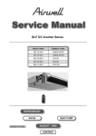
1
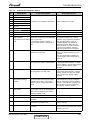
GCD 030 Series
Indoor Units
Outdoor Units
PNX 30 DCI
SX 30 DCI
GCD 030
CKD 30 DCI
DLS 30 DCI
REFRIGERANT
R410A
SM GCD030 1-A.0 GB
HEAT PUMP
JULY 2009
CONTENTS
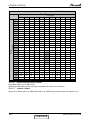
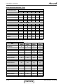
LIST OF EFFECTIVE PAGES
LIST OF EFFECTIVE PAGES
Note: Changes in the pages are indicated by a “Revision#” in the footer of each effected page
(when none indicates no changes in the relevant page). All pages in the following list represent
effected/ non effected pages divided by chapters.
Dates of issue for original and changed pages are:
Original ....... 0 ........ April 2009
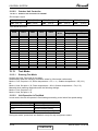
Total number of pages in this publication is 95 consisting of the following:
Page
No.
Revision
No. #
Page
No.
Revision
No. #
Page
No.
Revision
No. #
Title .......................0
A ...........................0
i .............................0
1-1 - 1-4 ................0
2-1 - 2-4 ................0
3-1 ........................0
4-1 - 4-3 ................0
5-1 - 5-20 ..............0
6-1 ........................0
7-1 - 7-3 ................0
8-1 ........................0
9-1 - 9-4 ................0
10-1-10-4 ..............0
11-1 .......................0
12-1- 2-19 .............0
13-1-13-11 ............0
14-1-14-9 ..............0
15-1 ......................0
•
Zero in this column indicates an original page.
* Due to constant improvements please note that the data on this service manual can be modified with out notice.
** Photos are not contractual.
SM GCD030 1-A.0 GB
A
CONTENTS
TABLE OF CONTENTS
Table of Contents
1.
INTRODUCTION ...................................................................................................1-1
2.
PRODUCT DATA SHEET ......................................................................................2-1
3.
RATING CONDITIONS ..........................................................................................3-1
4.
OUTLINE DIMENSIONS .......................................................................................4-1
5.
PERFORMANCE DATA & PRESSURE CURVES ................................................5-1
6.
AIRFLOW CURVES ..............................................................................................6-1
7.
SOUND LEVEL CHARACTERISTICS ..................................................................7-1
8.
ELECTRICAL DATA ..............................................................................................8-1
9.
WIRING DIAGRAMS .............................................................................................9-1
10. REFRIGERATION DIAGRAMS .............................................................................10-1
11.
TUBING CONNECTIONS......................................................................................11-1
12. CONTROL SYSTEM .............................................................................................12-1
13. TROUBLESHOOTING ..........................................................................................13-1
14. EXPLODED VIEWS AND SPARE PARTS LISTS .................................................14-1
15. APPENDIX A .........................................................................................................15-1
SM GCD030 1-A.0 GB
i
INTRODUCTION
1.
INTRODUCTION
1.1
General
The GCD 030 R410A can be matched to the following models:
● PNX 30 DCI
● SX 30 DCI
● CKD 30 DCI
● DLS 30 DCI
Remote control compatibility
The PNX, SX, CKD, DLS units are compatible with remote controls RC3, RC4, RCW1,
RCW2.
1.2
Main Features
The GCD 030 benefits from the most advanced technological innovations, namely:
● Sine wave form in both OFAN and Compressor drives.
● Partial switching PFC control.
● Fuzzy Logic Control (automatic control)
● R410A
● High COP (“A” class energy rating)
● Low noise levels
● Networking connectivity.
● Pre-charged system.
● Dry contact inputs and outputs:
▪
▪
▪
▪
▪
▪
STBY
Night mode
Power Shedding
Forced Mode operation
Dry contact output – Alarm.
Base heater
● Cooling operation at outdoor temperature down to -10°C
● Heating operation at outdoor temperature down to -15°C
● Up to 30m (DLS 50m) pipe length between indoor and outdoor units
● Up to 15m vertical high between indoor and outdoor units
● Support HMI Display Board (Human-Machine Interface) – 3x7-segment display
shows system status and settings.
● Easy installation and maintenance.
SM GCD030 1-A.0 GB
1-1
CONTENTS
INTRODUCTION
1.3
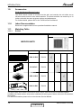
Indoor Units
The DLS 30 indoor unit is a low silhouette ducted unit, and can be easily fitted to many
types of
residential and commercials applications.
It includes:
• High technology plastic fan and fan housing.
• A drain pool that is under the entire unit with internal downward slope.
• An over-flow switch, stops compressor operation in case of is blocked drainage.
• A bended coil with treated aluminium fins.
• 3-speed fan motor an extra speed in case a higher external static pressure isneeded.
• Advanced electronic control box assembly.
• All the tubing connections are in the back of the unit to allow easy outlet to left or right
side of the unit.
• Field options:
(1) External water pump
(2) Airconet connection
(3) Plenum kit for connection of flexible hoses at air outlet.
1.3.1
Indoor Unit: CKD 30
The indoor unit is ceiling mounted, and can be easily fitted to residential and
commercial applications
It includes:
• A large diameter centrifugal fan, allowing low noise level operation
• Motorized flaps
• Bended indoor coil with hydrophilic aluminum fins.
• Advanced electronic control boc assembly.
1.3.2
Indoor Unit: SX 30
The indoor unit is cellingl mounted, and can be easily fitted to many types of residential
and commercials applications.
It includes:
• Coil with hydrophilic aluminum fins.
• Motorized flaps (two step motors)
• Advanced electronic control box assembly (DCI storm)
1.3.3
• Mounting plate
Indoor Unit: PNX 30
The indoor unit is wall mounted, and can be easily fitted to many types of residential
and commercials applications.
Indoor Unit features:
SM GCD030 1-A.0 GB
1-2
CONTENTS
INTRODUCTION
1.4
Feature
PNX 30
Display
Ionizer
ESF
Fresh air
Indoor fan motor
Horizontal motorized louver
Vertical motorized louver
Heating element
M2L Cable port
Dry contact
LCD
Yes
Yes
No
Variable Speed (PG)
Yes
Yes
No
Yes
Presence detector or (Jumper selected) power shedding
Filtration
• The unit is equipped with pre filters.
• Easy and versatile access, rear or bottom, can be easily adjusted by the installer.
1.5
Ionizer (Optional)
A special design Ioniser protected by unique patents integrated into the indoor unit,
generating negative ions to the room providing comfort and upgraded indoor air quality.
1.6
Control
The microprocessor indoor controller, and an infrared remote control, supplied as
standard, provide complete operating function and programming.
For further details, please refer to the Operation Manual, Appendix A.
1.7
Outdoor Unit
The GCD 030 outdoor units can be installed as floor or wall mounted units by using a wall
supporting bracket. The metal sheets are protected by anti- corrosion paint work allowing
long life resistance. All outdoor units are pre-charged. For further information, please
refer to the Product Data Sheet, Chapter 2.
It includes:
● Compressor mounted in a soundproofed compartment :
Dual Rotary – for GCD 030
● Improved 3- blades axial fans for noise reduction.
● Fan grill air outlet.
● Service valves ”flare” type connection.
● Service ports for high/ low pressure measurement.
● Advanced controller.
● Outdoor coil with hydrophilic louver fins.
Feature
Diagnostics Display
Outdoor Fan
M2L cable Port
1.8
GCD 030
3 LED`s
Variable speed DC Inverter
No
Tubing Connections
Flare type-interconnecting tubing to be produced on site.
All the units from 7KW and up can be installed with 50-meter tubing length and 25-meter
height difference without oil traps.
For further details, please refer to the Installation Manual, Appendix A.
SM GCD030 1-A.0 GB
1-3
CONTENTS
INTRODUCTION
1.9
Accessories
RCW Wall Mounted Remote Control
The RCW remote control is mounted on the wall, and controls the unit either as an
infrared remote control or as a wired controller. The wired controller can control up to 10
Indoor units with the same program settings and adjustments.
For further details, please refer to the Technical Service Manual.
1.10
Inbox Documentation
Each unit is supplied with its own operation/installation manual.
1.11
Matching Table
1.11.1
R410A
OUTDOOR UNIT
INDOOR UNITS
MODEL
REFRIGER.
PNX 30 DCI
R410A
SX 30 DCI
R410A
CKD 30 DCI
R410A
DLS 30 DCI
R410A
GCD 030
√
√
√
√
The above table lists outdoor units and DLS/DCI indoor units which can be matched together.
In addition the listed outdoor units can be matched with other types of indoor units such as cassettes,
floor/ceiling.
For further information please refer to the relevant Service Manual.
SM GCD030 1-A.0 GB
1-4
CONTENTS
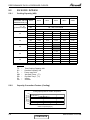
PRODUCT DATA SHEET
2.
PRODUCT DATA SHEET
2.1
PNX 30 DCI / GCD 030
PNX 30 DCI
GCD 030 R410A
Model Indoor Unit
Model Outdoor Unit
Installation Method of Pipe
Characteristics
Flared
Units
Btu/hr
kW
kW
W/W
Capacity (4)
Power input (4)
EER (Cooling) or COP(Heating) (4)
Energy efficiency class
Power supply
OUTDOOR
INDOOR
Rated current
Power factor
Prated (IDU)
Prated (IDU+ODU)
Starting current
Circuit breaker rating
Fan type & quantity
Fan speeds
H/M/L
H/M/L
Air flow (1)
External static pressure
Min
H/M/L
Sound power level (2)
H/M/L
Sound pressure level (3)
Moisture removal
Condenstate drain tube I.D
Dimensions
WxHxD
Net Weight
Package dimensions
WxHxD
Packaged weight
Units per pallet
Stacking height
Refrigerant control
Compressor type,model
Fan type & quantity
Fan speeds
H
Air flow
H
Sound power level
H
H
Sound pressure level (3)
Dimensions
WxHxD
Net Weight
Package dimensions
WxHxD
Packaged weight
Units per pallet
Stacking height
Refrigerant type
Standard charge
Additional charge
Liquid line
Suction line
Connections
Max.tubing length
between units
Max.height
difference
Operation control type
Heating elements (Option)
Others
(1)
(2)
(3)
(4)
In.(mm)
In.(mm)
m.
Heating
29010(5100~32420)
8.5(1.5~9.5)
2.65(0.5~3.2)
3.21
C
220-240
1
50
11.3
11.5
0.97
0.97
105
3200
15
25
Crossflow x 1
1300/1150/1000
1250/1050/900
0
66/61/57
51/48/44
3
16
1200x340x236
18.5
1304x430x325
24
12
6 levels
EEV
Two Rotary,Sanyo(Sheny) C-7RVN153H0W
Propeller(direct) x 1
850
3600
66
56
1040x864x412
66
1140x930x510
73.5
4
2 levels
R410A
2.5
7.5m<Length≤20m:+0g; 20m<Length≤30m:+250g
3/8"(9.53)
5/8"(15.88)
Max.30
m.
Max.15
V
Ph
Hz
A
W
W
A
A
RPM
m3/hr
Pa
dB(A)
dB(A)
l/hr
mm
mm
kg
mm
kg
units
units
RPM
m3/hr
dB(A)
dB(A)
mm
kg
mm
kg
Units
units
kg(7.5m)
Cooling
26620(5100~30035)
7.8(1.5-8.8)
2.59(0.5-3.1)
3.01
B
Remote control
kW
Rating conditions in accordance with ISO 5151 and ISO 13253 (for ducted units).
Airflow in ducted units; at nominal external static pressure.
Sound power in ducted units is measured at air discharge.
Sound pressure level measured at 1.4 meter distance from unit.
SM GCD030 1-A.0 GB
2-1
CONTENTS
PRODUCT DATA SHEET
2.2
SX 30 DCI / GCD 030
SX 30 DCI
GCD 030 R410A
Model Indoor Unit
Model Outdoor Unit
Installation Method of Pipe
Characteristics
Units
Btu/hr
kW
kW
W/W
Capacity (4)
Power input (4)
EER (Cooling) or COP(Heating) (4)
Energy efficiency class
Power supply
OUTDOOR
INDOOR
Rated current
Power factor
Prated (IDU)
Prated (IDU+ODU)
Starting current
Circuit breaker rating
Fan type & quantity
Fan speeds
H/M/L
H/M/L
Air flow (1)
External static pressure
Min
H/M/L
Sound power level (2)
H/M/L
Sound pressure level (3)
Moisture removal
Condenstate drain tube I.D
Dimensions
WxHxD
Net Weight
Package dimensions
WxHxD
Packaged weight
Units per pallet
Stacking height
Refrigerant control
Compressor type,model
Fan type & quantity
Fan speeds
H
Air flow
H
Sound power level
H
H
Sound pressure level (3)
Dimensions
WxHxD
Net Weight
Package dimensions
WxHxD
Packaged weight
Units per pallet
Stacking height
Refrigerant type
Standard charge
Additional charge
Liquid line
Suction line
Connections
between units
Max.tubing length
Max.height difference
Operation control type
Heating elements (Option)
Others
(1)
(2)
(3)
(4)
V
Ph
Hz
A
W
W
A
A
RPM
m3/hr
Pa
dB(A)
dB(A)
l/hr
mm
mm
kg
mm
kg
units
units
RPM
m3/hr
dB(A)
dB(A)
mm
kg
mm
kg
Units
units
kg(7.5m)
In.(mm)
In.(mm)
m.
m.
Flared
Cooling
Heating
25590(5460~29340)
29680(6140~33440)
7.5(1.6-8.6)
8.7(1.8~9.8)
2.49(0.5-3.1)
2.55(0.5~2.8)
3.01
3.41
B
B
220-240
1
50
11.1
11.4
0.97
0.97
125
3200
15
25
Centifugal x 2
1300/1200/1050
1020/950/800
0
66/63/58
54/51/46
3.0
16
1200x630x190
32.0
1300x726x273
36
7
7 levels
EEV
Two Rotary,Sanyo(Sheny) C-7RVN153H0W
Propeller(direct) x 1
850
3600
69
58
950x864x413
66
1140x930x510
73.5
4
2 levels
R410A
2.5
7.5mLength≤20m:+0g; 20m<Length≤30m:+250g
3/8"(9.53)
5/8"(15.88)
Max.30
Max.15
Remote control
kW
Rating conditions in accordance with ISO 5151 and ISO 13253 (for ducted units).
Airflow in ducted units; at nominal external static pressure.
Sound power in ducted units is measured at air discharge.
Sound pressure level measured at 1.4 meter distance from unit.
SM GCD030 1-A.0 GB
2-2
CONTENTS
PRODUCT DATA SHEET
2.3
CKD 30 DCI / GCD 030
Model Indoor Unit
Model Outdoor Unit
CKD 30 DCI
GCD 030 R410A
Installation Method of Pipe
Characteristics
Units
Btu/hr
kW
kW
W/W
Capacity (4)
Power input (4)
EER (Cooling) or COP(Heating) (4)
Energy efficiency class
Power supply
OUTDOOR
INDOOR
Rated current
Power factor
Prated (IDU)
Prated (IDU+ODU)
Starting current
Circuit breaker rating
Fan type & quantity
Fan speeds
H/M/L
H/M/L
Air flow (1)
External static pressure
Min
H/M/L
Sound power level (2)
H/M/L
Sound pressure level (3)
Moisture removal
Condenstate drain tube I.D
Dimensions
WxHxD
Net Weight
Package dimensions
WxHxD
Packaged weight
Units per pallet
Stacking height
Refrigerant control
Compressor type,model
Fan type & quantity
Fan speeds
H
Air flow
H
Sound power level
H
H
Sound pressure level (3)
Dimensions
WxHxD
Net Weight
Package dimensions
WxHxD
Packaged weight
Units per pallet
Stacking height
Refrigerant type
Standard charge
Additional charge
Liquid line
Connections between Suction line
Max.tubing length
units
Max.height difference
Operation control type
Heating elements (Option)
Others
(1)
(2)
(3)
(4)
V
Ph
Hz
A
W
W
A
A
RPM
m3/hr
Pa
dB(A)
dB(A)
l/hr
mm
mm
kg
mm
kg
units
units
RPM
m3/hr
dB(A)
dB(A)
mm
kg
mm
kg
Units
units
kg(7.5m)
In.(mm)
In.(mm)
m.
m.
Flared
Cooling
Heating
27280(6800~30000)
30690(5110~34100)
8.0(2.0-8.8)
9.0(1.5~10.0)
2.49(0.5-3.2)
2.49(0.5~3.1)
3.21
3.61
A
A
220-230
1
50
11.1
11.1
0.97
0.97
140
3200
15
25
Centrifugal x 1
610/570/540
1170/1080/990
0
56/53/51
44/42/40
3
32
840x840x300
32
955x955x317
40
6
6 levels
EEV
Two Rotary,Sanyo(Sheny) C-7RVN153H0W
Propeller(direct) x 1
850
3600
69
58
950x864x413
66
1140x930x510
73.5
4
2 levels
R410A
2.5
7.5m<Length≤20m:+0g; 20m<Length≤30m:+250g
3/8"(9.53)
5/8"(15.88)
Max.30
Max.15
Remote control
kW
Rating conditions in accordance with ISO 5151 and ISO 13253 (for ducted units).
Airflow in ducted units; at nominal external static pressure.
Sound power in ducted units is measured at air discharge.
Sound pressure level measured at 1.4 meter distance from un
SM GCD030 1-A.0 GB
2-3
CONTENTS
PRODUCT DATA SHEET
2.4
DLS 30 DCI / GCD 030
DLS 30 DCI
GCD 030 R410A
Model Indoor Unit
Model Outdoor Unit
Installation Method of Pipe
Characteristics
Units
Btu/hr
kW
kW
W/W
Capacity (4)
Power input (4)
EER (Cooling) or COP(Heating) (4)
Energy efficiency class
V
Ph
Hz
A
Power supply
OUTDOOR
INDOOR
Rated current
Power factor
Prated (IDU)
Prated (IDU+ODU)
Starting current
Circuit breaker rating
Fan type & quantity
Fan speeds
Air flow (1)
External static pressure
Sound power level (2)
Sound pressure level (3)
Moisture removal
Condenstate drain tube I.D
Dimensions
Net Weight
Package dimensions
Packaged weight
Units per pallet
Stacking height
Refrigerant control
Compressor type,model
Fan type & quantity
Fan speeds
Air flow
Sound power level
Sound pressure level (3)
Dimensions
Net Weight
Package dimensions
Packaged weight
Units per pallet
Stacking height
Refrigerant type
Standard charge
W
W
A
A
T/H/M/L
T/H/M/L
Min
H/M/L
H/M/L
WxHxD
WxHxD
H
H
H
H
WxHxD
WxHxD
RPM
m3/hr
Pa
dB(A)
dB(A)
l/hr
mm
mm
kg
mm
kg
units
units
RPM
m3/hr
dB(A)
dB(A)
mm
kg
mm
kg
Units
units
kg(7.5m)
Additional charge
Liquid line
Connections between Suction line
Max.tubing length
units
Max.height difference
Operation control type
Heating elements (Option)
Others
(1)
(2)
(3)
(4)
In.(mm)
In.(mm)
m.
m.
Flared
Cooling
Heating
25590(5460-30710)
29340(6140-35830)
7.5(1.6-9.0)
8.6(1.8-10.5)
2.48(0.55-3.15)
2.68(0.5-2.8)
3.02
3.21
B
C
220-240
1
50
11.1
12.0
0.97
0.97
260
3200
15
25
Centrifugal x 1
800/670/550
1320/1150/935
25
64/61/58
48/44/40
1.5
22
770x690x260
31
959x854x315
33
6
6
EEV
Two Rotary,Sanyo(Sheny) C-7RVN153H0W
Propeller(direct) x 1
850
3600
66
56
1040x864x412
66
1140x930x510
73.5
4
2 levels
R410A
2.5
7.5m<Length≤20m:+0g;
20m<Length≤30m:+250g;
30m<Length≤50m:+1450g;
3/8"(9.53)
5/8"(15.88)
Max.50
Max.25
Remote control
kW
Rating conditions in accordance with ISO 5151 and ISO 13253 (for ducted units).
Airflow in ducted units; at nominal external static pressure.
Sound power in ducted units is measured at air discharge.
Sound pressure level measured at 1.4 meter distance from unit.
SM GCD030 1-A.0 GB
2-4
CONTENTS
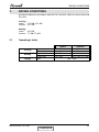
RATING CONDITIONS
3.
RATING CONDITIONS
Standard conditions in accordance with ISO 5151 and ISO 13253 (for ducted units) and
EN 14511.
Cooling:
Indoor:
27oC DB 19oC WB
Outdoor: 35 oC DB
Heating:
Indoor:
20oC DB
Outdoor: 7oC DB 6oC WB
3.1
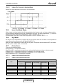
Operating Limits
Indoor
Cooling
Heating
Voltage
Upper limit
Lower limit
Upper limit
Lower limit
1PH
SM GCD030 1-A.0 GB
Outdoor
32oC DB 23oC WB 46oC DB
21oC DB 15oC WB -10oC DB
27oC DB
24oC DB 18oC WB
10oC DB
-15oC DB -16oC WB
198 – 264V
3-1
CONTENTS
OUTLINE DIMENSIONS
4.
OUTLINE DIMENSIONS
4.1
Indoor Unit: DLS 30 DCI
Model
DLS 30
A
B
C
790 653 749
D
758
E
797
SM GCD030 1-A.0 GB
F
256
G
195
H
702
I
599
J
K
L
684 162 242
4-1
CONTENTS
OUTLINE DIMENSIONS
Indoor Unit: PNX 30 DCI
4.3
Indoor Unit: SX 30 DCI
5 mm1 0
4.2
630
0
120
190
SM GCD030 1-A.0 GB
4-2
CONTENTS
OUTLINE DIMENSIONS
4.4
Indoor Unit: CKD 30 DCI
KN 60 DCIǃKN 72 DCI: B=240mm
KN 80 DCI: B=310mm
Remark: KN 60 DCI is the same as KN 72 DCI
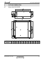
4.4
Outdoor Unit: GCD 030
SM GCD030 1-A.0 GB
4-3
CONTENTS
PERFORMANCE DATA & PRESSURE CURVES
5.
PERFORMANCE DATA & PRESSURE CURVES
5.1
PNX 30 DCI / GCD 030
5.1.1
Cooling Capacity (kW)
ID COIL ENTERING AIR DB/WB TEMPERATURE [C0]
OD COIL
ENTERING AIR DB
TEMPERATURE [C0]
DATA
-10 - 20
(protection range)
25
30
35
40
46
22/15
24/17
27/19
29/21
TC
80 - 110 % of nominal
SC
80 - 105 % of nominal
PI
25 - 50 % of nominal
32/23
TC
7.54
8.03
8.53
9.02
9.51
SC
5.36
5.47
5.57
5.68
5.79
PI
2.04
2.07
2.11
2.15
2.19
TC
7.18
7.67
8.16
8.66
9.15
SC
5.22
5.33
5.66
2.27
2.31
5.44
2.35
5.55
PI
2.39
2.43
TC
6.81
7.31
8.29
8.79
SC
5.09
5.19
5.41
5.52
PI
2.51
2.55
7.80
5.30
2.59
2.63
2.67
TC
6.45
6.94
8.42
4.95
5.06
7.44
5.17
7.93
SC
5.28
5.39
PI
2.75
2.79
2.83
2.87
2.91
TC
6.02
6.51
7.00
7.50
7.99
SC
4.79
3.04
4.90
3.08
5.01
3.11
5.12
3.15
5.22
3.19
PI
LEGEND
TC
SC
PI
WB
DB
ID
OD
5.1.2
–
–
–
–
–
–
–
Total Cooling Capacity, kW
Sensible Capacity, kW
Power Input, kW
Wet Bulb Temp., (oC)
Dry Bulb Temp., (oC)
Indoor
Outdoor
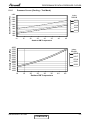
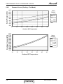
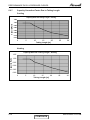
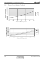
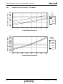
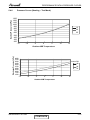
Capacity Correction Factors (Cooling)
Capacity Ratio
Cooling Capacity Ratio Vs. Outdoor Temperature
1.20
1.10
1.00
0.90
0.80
0.70
0.60
0.50
20
25
30
35
40
45
Outdoor Temperature [deg C]
SM GCD030 1-A.0 GB
5-1
CONTENTS
PERFORMANCE DATA & PRESSURE CURVES
5.1.3
Heating
ID COIL ENTERING AIR DB TEMPERATURE [C0]
OD COIL ENTERING
AIR DB/WB
TEMPERATURE [C0]
-15/-16
-10/-12
-7/-8
-1/-2
2/1
7/6
10/9
15/12
DATA
15
20
25
TC
PI
5.41
1.59
5.03
1.75
4.65
1.91
TC
6.02
5.64
5.27
PI
1.92
2.08
2.24
TC
6.48
6.10
5.72
PI
2.16
2.32
2.49
TC
6.71
6.33
5.95
PI
2.28
2.45
2.61
TC
6.86
6.49
2.53
6.11
PI
2.37
TC
8.88
PI
2.49
TC
9.37
PI
2.69
8.50
2.65
8.12
8.61
2.64
8.99
2.80
2.96
TC
9.86
9.48
9.10
PI
2.79
2.95
3.11
2.81
15-24
TC
85 - 105 % of nominal
(Protection Range)
PI
80 - 120 % of nominal
LEGEND
TH
PI
WB
DB
ID
OD
5.1.4
–
–
–
–
–
–
Total Heating Capacity, kW
Power Input, kW
Wet Bulb Temp., (oC)
Dry Bulb Temp., (oC)
Indoor
Outdoor
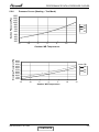
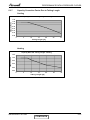
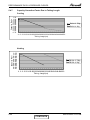
Capacity Correction Factors (Heating)
Capacity Ration
Heating Capacity Ratio Vs. Outdoor Temperature
1.20
1.10
1.00
0.90
0.80
0.70
0.60
0.50
-15
-10
-5
0
5
10
15
Outdoor WB Temperature [deg C]
SM GCD030 1-A.0 GB
5-2
CONTENTS
PERFORMANCE DATA & PRESSURE CURVES
Pressure Curves (Cooling – Test Mode)
5.1.5
Suction Pressure [kPa]
1400
Indoor
DB/WB
1300
1200
22/15
1100
24/17
1000
900
27/19
29/21
800
32/23
700
600
500
10
15
20
25
30
35
40
45
Discharge Pressure [kPa]
Outdoor DB Temperature
4000
3750
3500
3250
3000
2750
2500
2250
2000
1750
1500
1250
1000
Indoor
DB/WB
22/15
24/17
27/19
29/21
32/23
10
15
20
25
30
35
40
45
Outdoor DB Temperature
SM GCD030 1-A.0 GB
5-3
CONTENTS
PERFORMANCE DATA & PRESSURE CURVES
Pressure Curves (Heating – Test Mode)
5.1.6
Suction Pressure [kPa]
1300
1200
1100
1000
900
800
700
600
500
400
300
200
15
20
25
-15
-10
-5
0
5
10
15
Discharge Pressure [kPa]
Outdoor WB Temperature
4000
3750
3500
3250
3000
2750
2500
2250
2000
1750
1500
Indoor DB
15
20
25
-15
-10
-5
0
5
10
15
Outdoor WB Temperature
SM GCD030 1-A.0 GB
5-4
CONTENTS
PERFORMANCE DATA & PRESSURE CURVES
5.1.7
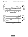
Capacity Correction Factor Due to Tubing Length
Cooling
Capacity Ratio VS.Tubing Length - Cooling
Capacity Ratio
1.02
1.00
0.98
0.96
0.94
0.92
0.90
0.88
0
5
10
15
20
Tubing Length [m]
25
30
Heating
Capacity Ratio VS. Tubing Length - Heating
Capacity Ratio
1.02
1.00
0.98
0.96
0.94
0.92
0.90
0.88
0
5
10
15
20
Tubing Length [m]
SM GCD030 1-A.0 GB
25
30
5-5
CONTENTS
PERFORMANCE DATA & PRESSURE CURVES
5.2
SX 30 DCI / GCD 030
5.2.1
Cooling Capacity (kW)
ID COIL ENTERING AIR DB/WB TEMPERATURE [C0]
OD COIL
ENTERING AIR DB
TEMPERATURE [C0]
DATA
-10 - 20
(protection range)
22/15
24/17
30
35
40
46
29/21
TC
80 - 110 % of nominal
SC
80 - 105 % of nominal
PI
25
27/19
32/23
25 - 50 % of nominal
TC
7.25
7.72
8.20
8.67
9.15
SC
5.15
5.26
5.36
5.47
5.57
PI
1.98
2.02
2.05
2.09
2.13
TC
6.90
7.37
7.85
8.32
8.80
SC
5.02
5.12
5.44
2.21
2.25
5.23
2.29
5.34
PI
2.32
2.36
TC
6.55
7.03
7.97
8.45
SC
4.89
4.99
5.21
5.31
PI
2.44
2.48
7.50
5.10
2.52
2.56
2.59
TC
6.20
6.68
7.63
8.10
SC
4.76
4.86
7.15
4.97
5.08
5.18
PI
2.67
2.71
2.75
2.79
2.83
TC
5.78
6.26
6.73
7.21
7.68
SC
4.60
2.95
4.71
2.99
4.81
3.03
4.92
3.07
5.02
3.10
PI
LEGEND
TC
SC
PI
WB
DB
ID
OD
5.2.2
–
–
–
–
–
–
–
Total Cooling Capacity, kW
Sensible Capacity, kW
Power Input, kW
Wet Bulb Temp., (oC)
Dry Bulb Temp., (oC)
Indoor
Outdoor
Capacity Correction Factors (Cooling)
Capacity Ratio
Cooling Capacity Ratio Vs. Outdoor Temperature
1.20
1.10
1.00
0.90
0.80
0.70
0.60
0.50
20
25
30
35
40
45
Outdoor Temperature [deg C]
SM GCD030 1-A.0 GB
5-6
CONTENTS
PERFORMANCE DATA & PRESSURE CURVES
5.2.3
Heating
ID COIL ENTERING AIR DB TEMPERATURE [C0]
OD COIL ENTERING
AIR DB/WB
TEMPERATURE [C0]
-15/-16
-10/-12
-7/-8
-1/-2
2/1
7/6
10/9
15/12
DATA
15
20
25
TC
PI
5.54
1.57
5.15
1.73
4.76
1.89
TC
6.16
5.78
5.39
PI
1.90
2.06
2.22
TC
6.63
6.25
5.86
PI
2.14
2.30
2.46
TC
6.87
6.48
6.09
PI
2.26
2.42
2.58
TC
7.03
6.64
2.50
6.25
8.70
2.62
8.31
PI
2.34
TC
9.09
PI
2.46
TC
9.59
PI
2.66
2.78
8.81
2.61
9.20
2.77
2.93
TC
10.09
9.70
9.32
PI
2.76
2.92
3.08
15-24
TC
85 - 105 % of nominal
(Protection Range)
PI
80 - 120 % of nominal
LEGEND
TH
PI
WB
DB
ID
OD
5.2.4
–
–
–
–
–
–
Total Heating Capacity, kW
Power Input, kW
Wet Bulb Temp., (oC)
Dry Bulb Temp., (oC)
Indoor
Outdoor
Capacity Correction Factors (Heating)
Capacity Ration
Heating Capacity Ratio Vs. Outdoor Temperature
1.20
1.10
1.00
0.90
0.80
0.70
0.60
0.50
-15
-10
-5
0
5
10
15
Outdoor WB Temperature [deg C]
SM GCD030 1-A.0 GB
5-7
CONTENTS
PERFORMANCE DATA & PRESSURE CURVES
Pressure Curves (Cooling – Test Mode)
5.2.5
Suction Pressure [kPa]
1400
Indoor
DB/WB
1300
1200
22/15
1100
24/17
1000
900
27/19
29/21
800
32/23
700
600
500
10
15
20
25
30
35
40
45
Discharge Pressure [kPa]
Outdoor DB Temperature
4000
3750
3500
3250
3000
2750
2500
2250
2000
1750
1500
1250
1000
Indoor
DB/WB
22/15
24/17
27/19
29/21
32/23
10
15
20
25
30
35
40
45
Outdoor DB Temperature
SM GCD030 1-A.0 GB
5-8
CONTENTS
PERFORMANCE DATA & PRESSURE CURVES
Pressure Curves (Heating – Test Mode)
Suction Pressure [kPa]
5.2.6
1300
1200
1100
1000
900
800
700
600
500
400
300
200
15
20
25
-15
-10
-5
0
5
10
15
Discharge Pressure [kPa]
Outdoor WB Temperature
4000
3750
3500
3250
3000
2750
2500
2250
2000
1750
1500
Indoor DB
15
20
25
-15
-10
-5
0
5
10
15
Outdoor WB Temperature
SM GCD030 1-A.0 GB
5-9
CONTENTS
PERFORMANCE DATA & PRESSURE CURVES
5.2.7
Capacity Correction Factor Due to Tubing Length
Cooling
Capacity Ratio VS. Tubing Length - Cooling
1.05
Capacity Ratio
1.00
0.95
0.90
0.85
0.80
0.75
0.70
0
5
10
15
20
25
30
25
30
Tubing Length [m]
Heating
Capacity Ratio VS. Tubing Length - Heating
Capacity Ratio
1.05
1.00
0.95
0.90
0.85
0.80
0
5
10
15
20
Tubing Length [m]
SM GCD030 1-A.0 GB
5-10
CONTENTS
PERFORMANCE DATA & PRESSURE CURVES
5.3
CKD 30 DCI / GCD 030
5.3.1
Cooling Capacity (kW)
ID COIL ENTERING AIR DB/WB TEMPERATURE [C0]
OD COIL
ENTERING AIR DB
TEMPERATURE [C0]
DATA
22/15
24/17
27/19
29/21
32/23
-10 - 20
(protection range)
TC
80 - 110 % of nominal
SC
80 - 105 % of nominal
PI
25 - 50 % of nominal
TC
7.73
8.24
8.74
9.25
9.76
25
SC
5.49
5.61
5.72
5.83
5.94
PI
1.96
1.99
2.03
2.07
2.11
TC
7.36
7.87
8.37
8.88
9.38
SC
5.35
5.47
5.58
2.26
5.69
5.80
2.30
2.34
8.00
5.44
2.49
8.51
9.01
5.55
5.66
2.53
2.56
7.63
5.30
8.13
8.64
5.41
5.53
30
35
40
46
PI
2.19
2.22
TC
6.99
7.49
SC
5.22
5.33
PI
2.42
2.45
TC
6.62
7.12
SC
5.08
5.19
PI
2.64
2.68
2.72
2.76
2.79
TC
6.17
6.68
7.18
7.69
8.19
SC
4.91
2.92
5.02
2.96
5.13
2.99
5.25
3.03
5.36
3.07
PI
LEGEND
TC
SC
PI
WB
DB
ID
OD
5.3.2
–
–
–
–
–
–
–
Total Cooling Capacity, kW
Sensible Capacity, kW
Power Input, kW
Wet Bulb Temp., (oC)
Dry Bulb Temp., (oC)
Indoor
Outdoor
Capacity Correction Factors (Cooling)
Capacity Ratio
Cooling Capacity Ratio Vs. Outdoor Temperature
1.20
1.10
1.00
0.90
0.80
0.70
0.60
0.50
20
25
30
35
40
45
Outdoor Temperature [deg C]
SM GCD030 1-A.0 GB
5-11
CONTENTS
PERFORMANCE DATA & PRESSURE CURVES
5.3.3
Heating
ID COIL ENTERING AIR DB TEMPERATURE [C0]
OD COIL ENTERING
AIR DB/WB
TEMPERATURE [C0]
-15/-16
-10/-12
-7/-8
-1/-2
2/1
7/6
10/9
15/12
DATA
15
20
25
TC
PI
5.73
1.49
5.33
1.65
4.93
1.80
TC
6.38
5.98
5.58
PI
1.80
1.95
2.11
TC
6.86
6.46
6.06
PI
2.03
2.18
2.34
TC
7.11
6.71
6.30
PI
2.15
2.30
2.45
TC
7.27
6.47
PI
2.22
6.87
2.37
TC
9.40
8.60
PI
2.34
9.00
2.49
2.64
TC
9.92
PI
2.48
9.52
2.63
2.78
TC
10.44
10.04
9.64
PI
2.62
2.77
2.92
2.53
9.12
15-24
TC
85 - 105 % of nominal
(Protection Range)
PI
80 - 120 % of nominal
LEGEND
TH
PI
WB
DB
ID
OD
5.3.4
–
–
–
–
–
–
Total Heating Capacity, kW
Power Input, kW
Wet Bulb Temp., (oC)
Dry Bulb Temp., (oC)
Indoor
Outdoor
Capacity Correction Factors (Heating)
Capacity Ration
Heating Capacity Ratio Vs. Outdoor Temperature
1.20
1.10
1.00
0.90
0.80
0.70
0.60
0.50
-15
-10
-5
0
5
10
15
Outdoor WB Temperature [deg C]
SM GCD030 1-A.0 GB
5-12
CONTENTS
PERFORMANCE DATA & PRESSURE CURVES
Pressure Curves (Cooling – Test Mode)
5.3.5
Suction Pressure [kPa]
1400
Indoor
DB/WB
1300
1200
22/15
1100
24/17
1000
900
27/19
29/21
800
32/23
700
600
500
10
15
20
25
30
35
40
45
Discharge Pressure [kPa]
Outdoor DB Temperature
4000
3750
3500
3250
3000
2750
2500
2250
2000
1750
1500
1250
1000
Indoor
DB/WB
22/15
24/17
27/19
29/21
32/23
10
15
20
25
30
35
40
45
Outdoor DB Temperature
SM GCD030 1-A.0 GB
5-13
CONTENTS
PERFORMANCE DATA & PRESSURE CURVES
Pressure Curves (Heating – Test Mode)
Suction Pressure [kPa]
5.3.6
1300
1200
1100
1000
900
800
700
600
500
400
300
200
15
20
25
-15
-10
-5
0
5
10
15
Discharge Pressure [kPa]
Outdoor WB Temperature
4000
3750
3500
3250
3000
2750
2500
2250
2000
1750
1500
Indoor DB
15
20
25
-15
-10
-5
0
5
10
15
Outdoor WB Temperature
SM GCD030 1-A.0 GB
5-14
CONTENTS
PERFORMANCE DATA & PRESSURE CURVES
5.3.7
Capacity Correction Factor Due to Tubing Length
Cooling
Capacity Ratio VS.Tubing Length - Cooling
Capacity Ratio
1.02
1.00
0.98
0.96
0.94
0.92
0.90
0.88
0
5
10
15
20
Tubing Length [m]
25
30
25
30
Heating
Capacity Ratio VS. Tubing Length - Heating
Capacity Ratio
1.05
1.00
0.95
0.90
0.85
0.80
0
5
10
15
20
Tubing Length [m]
SM GCD030 1-A.0 GB
5-15
CONTENTS
PERFORMANCE DATA & PRESSURE CURVES
5.4
DLS 30 DCI / GCD 030
5.4.1
Cooling Capacity (kW)
ID COIL ENTERING AIR DB/WB TEMPERATURE [C0]
OD COIL
ENTERING AIR DB
TEMPERATURE [C0]
DATA
-10 - 20
(protection range)
TC
80 - 110 % of nominal
SC
80 - 105 % of nominal
PI
25 - 50 % of nominal
25
30
35
40
46
22/15
24/17
27/19
29/21
32/23
TC
7.25
7.72
8.20
8.67
9.15
SC
5.15
5.26
5.36
5.47
5.57
PI
1.95
1.99
2.02
2.06
2.10
TC
6.90
7.37
7.85
8.32
8.80
SC
5.02
5.12
5.34
5.44
PI
2.18
2.21
5.23
2.25
2.29
2.33
TC
6.55
7.03
7.97
8.45
SC
4.89
4.99
7.50
5.10
2.48
5.21
5.31
2.52
2.55
7.63
8.10
5.08
5.18
PI
2.41
2.44
TC
6.20
6.68
SC
4.76
4.86
7.15
4.97
PI
2.63
2.67
2.71
2.75
2.78
TC
5.78
6.26
6.73
7.21
7.68
SC
4.60
2.91
4.71
2.94
4.81
2.98
4.92
3.02
5.02
3.06
PI
LEGEND
TC
SC
PI
WB
DB
ID
OD
5.4.2
–
–
–
–
–
–
–
Total Cooling Capacity, kW
Sensible Capacity, kW
Power Input, kW
Wet Bulb Temp., (oC)
Dry Bulb Temp., (oC)
Indoor
Outdoor
Capacity Correction Factors (Cooling)
Capacity Ratio
Cooling Capacity Ratio Vs. Outdoor Temperature
1.20
1.10
1.00
0.90
0.80
0.70
0.60
0.50
20
25
30
35
40
45
Outdoor Temperature [deg C]
SM GCD030 1-A.0 GB
5-16
CONTENTS
PERFORMANCE DATA & PRESSURE CURVES
5.4.3
Heating
ID COIL ENTERING AIR DB TEMPERATURE [C0]
OD COIL ENTERING
AIR DB/WB
TEMPERATURE [C0]
-15/-16
-10/-12
-7/-8
-1/-2
2/1
7/6
10/9
15/12
DATA
15
20
25
TH
PI
5.47
1.61
5.09
1.77
4.71
1.94
TH
6.09
5.71
5.33
PI
1.94
2.10
2.27
TH
6.56
6.17
5.79
PI
2.19
2.35
2.51
TH
6.79
6.41
6.02
PI
2.31
2.47
2.64
TH
6.94
2.39
6.56
2.56
6.18
PI
TH
8.98
8.22
PI
2.52
8.60
2.68
TH
9.48
8.71
2.99
2.72
2.84
PI
2.67
9.10
2.83
TH
9.97
9.59
9.21
PI
2.82
2.98
3.14
15-24
TH
85 - 105 % of nominal
(Protection Range)
PI
80 - 120 % of nominal
LEGEND
TH
PI
WB
DB
ID
OD
5.4.4
–
–
–
–
–
–
Total Heating Capacity, kW
Power Input, kW
Wet Bulb Temp., (oC)
Dry Bulb Temp., (oC)
Indoor
Outdoor
Capacity Correction Factors (Heating)
Capacity Ration
Heating Capacity Ratio Vs. Outdoor Temperature
1.20
1.10
1.00
0.90
0.80
0.70
0.60
0.50
-15
-10
-5
0
5
10
15
Outdoor WB Temperature [deg C]
SM GCD030 1-A.0 GB
5-17
CONTENTS
PERFORMANCE DATA & PRESSURE CURVES
Pressure Curves (Cooling – Test Mode)
5.4.5
Suction Pressure [kPa]
1400
Indoor
DB/WB
1300
1200
22/15
1100
24/17
1000
900
27/19
29/21
800
32/23
700
600
500
10
15
20
25
30
35
40
45
Discharge Pressure [kPa]
Outdoor DB Temperature
4000
3750
3500
3250
3000
2750
2500
2250
2000
1750
1500
1250
1000
Indoor
DB/WB
22/15
24/17
27/19
29/21
32/23
10
15
20
25
30
35
40
45
Outdoor DB Temperature
SM GCD030 1-A.0 GB
5-18
CONTENTS
PERFORMANCE DATA & PRESSURE CURVES
Pressure Curves (Heating – Test Mode)
Suction Pressure [kPa]
5.4.6
1300
1200
1100
1000
900
800
700
600
500
400
300
200
15
20
25
-15
-10
-5
0
5
10
15
Discharge Pressure [kPa]
Outdoor WB Temperature
4000
3750
3500
3250
3000
2750
2500
2250
2000
1750
1500
Indoor DB
15
20
25
-15
-10
-5
0
5
10
15
Outdoor WB Temperature
SM GCD030 1-A.0 GB
5-19
CONTENTS
PERFORMANCE DATA & PRESSURE CURVES
5.4.7
Capacity Correction Factor Due to Tubing Length
&DSDFL W \ 5DW L R
Cooling
5$ .J
5$ .J
7XEL QJ /HQJW K P
&DSDFL W \ 5DW L R
Heating
5$ .J
5$ .J
7XEL QJ /HQJW K P
SM GCD030 1-A.0 GB
5-20
CONTENTS
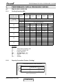
AIRFLOW CURVES
6.
AIRFLOW CURVES
6.1
Model: DLS 30 DCI
37
6.2
DLS UNITS RANGE AIR FLOW CORRECTION FACTORS
(at nominal rating conditions — Test mode).
Air Flow Rate [% of nominal]
Cooling
Heating
TC
SC
PI
PI
TC
60%
0.88
0.78
0.95
1.07
0.90
70%
0.91
0.84
0.97
1.05
0.92
80%
0.94
0.89
0.98
1.03
0.95
90%
0.97
0.95
0.99
1.02
0.97
100%
1
1
1
1
1
* Permissible Air flow Rate - according to model Air Flow Curves
SM GCD030 1-A.0 GB
6-1
CONTENTS
SOUND LEVEL CHARACTERISTICS
7.
SOUND LEVEL CHARACTERISTICS
7.1
Sound Pressure Level
7.2
Soud Pressure Level Spectrum
PNX 30
OCTAVE BAND SOUND PRESSURE LEVEL, dB re 0.002 MICRO BAR
DLS 30
NC-70
NC-60
NC-50
NC-40
NC-30
APPROXIMATE
THRESHOLD OF
HEARING FOR
CONTINUOUS
NOISE
NC-20
BAND CENTER FREQUENCIES, Hz
FAN SPEED
LINE
HI
ME
LO
SM GCD030 1-A.0 GB
7-1
CONTENTS
SOUND LEVEL CHARACTERISTICS
SX 30
FAN SPEED
CKD 30
LINE
HI
ME
LO
SM GCD030 1-A.0 GB
7-2
CONTENTS
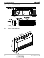
SOUND LEVEL CHARACTERISTICS
7.3
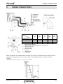
Outdoor units
Unit
1m
Mic.
Ground
Figure 2
7.4
Sound Pressure Level Spectrum (Measured as Figure 2)
GCD 030 Heating
-70NC
-60NC
-50NC
-40NC
-30NC
APPROXIMATE
THRESHOLD OF
HEARING FOR
CONTINUOUS
NOISE
-20NC
MICRO BAR0.002 dB re , OCTAVE BAND SOUND PRESSURE LEVEL
MICRO BAR0.002 dB re , OCTAVE BAND SOUND PRESSURE LEVEL
GCD 030 Cooling
Hz, BAND CENTER FREQUENCIES
SM GCD030 1-A.0 GB
-70NC
-60NC
-50NC
-40NC
-30NC
APPROXIMATE
THRESHOLD OF
HEARING FOR
CONTINUOUS
NOISE
-20NC
Hz, BAND CENTER FREQUENCIES
7-3
CONTENTS
ELECTRICAL DATA
8.
ELECTRICAL DATA
8.1
Single Phase Units
Model
PNX 30
Power Supply
Connected to
Maximum Current
Inrush Current
Starting Current
Circuit Breaker
Power Supply Wiring no х cross section
Interconnecting cable no х cross section
SX 30
CKD 30
DLS 30
1 PH ,220-240VAC ,50HZ
Outdoor
15A
15 A
15A
15A
45 A
15A
15A
25 A
3 X 2.5 mm²
4X 2.5 mm²
15A
15A
(a) Inrush current is the current when power is up (charging the DC capacitorsat outdoor unit
controller).
(b) Starting current is the current when starting the compressor.
NOTE:
Power wiring cord should comply with local lows and electrical regulations requirements.
SM GCD030 1-A.0 GB
8-1
CONTENTS
WIRING DIAGRAMS
9.
WIRING DIAGRAMS
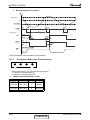
9.1
Indoor Unit: PNX 30 DCI
INDOOR UNIT
SM GCD030 1-A.0 GB
9-1
CONTENTS
WIRING DIAGRAMS
9.2
Indoor Unit: SX 30 DCI
SM GCD030 1-A.0 GB
9-2
CONTENTS
WIRING DIAGRAMS
9.3
Indoor Unit: CKD 30 DCI
9.4
Indoor Unit: DLS 30 DCI
SM GCD030 1-A.0 GB
9-3
CONTENTS
WIRING DIAGRAMS
9.5
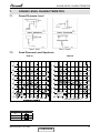
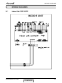
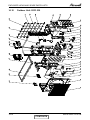
Outdoor Unit: GCD 030
OUTDOOR UNIT CIRCUIT DIAGRAM
P404
P405
P406
RED
WHITE
TO AC MAINS (FOR POWER
SOURCE FROM ODU)
P108
P107
CCH
FUSE
RV
4
3
M2L
P103
2
CN802
ON
P104
ODU3
1
ODU2
ODU1
MODEL_SET
DIP
P102
SELF
TEST
ODU0
CN801
2 4 6 8 101214
1 3 5 7 9 1113
FLASH_PORT
HMI
FB
L0
N0
LI
NI
TO IDU
COM
ODU MODEL SETTING
CN601
5 43 2 1 W V U U V W
BU
RD
BN
BK
EEV
OFAN
WH
RD
BLUE
BLUE
BROWN
BROWN
P106
P104
P103
P105
BLUE
P503
P502
P501
AUX
P601
65 43 2 1
N L P201 P202
P101
ODU0 ODU1 ODU2 ODU3 ODU MODEL
OFF OFF OFF OFF P(DCI80)
P604
P603
P602
HST CTT OCT OAT OMT
P701
P401
P804 P802 P803 P801
1 2 3 4 5 6 7 8 9 10 2 1 3 2 1 2 1 4 3 2 1 4 3 2 1
ODU
MSMP
-PWR
P403
3 2 1 432 1
P106 P105
P402
NIGHT
STANDBY PWR-SHED FORCED ALARM
COMP
WHITE
NOTE: WIRING SCHEME WITHIN
DASHED LINE BORDERS ARE
RELEVANT FOR SINGLE SPLIT
APPLICATIONS ONLY, FOR MULTI
SPLIT WIRING REFER TO MSMP
WIRING DIAGRAM.
SM GCD030 1-A.0 GB
9-4
CONTENTS
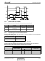
REFRIGERATION DIAGRAMS
10.
REFRIGERATION DIAGRAMS
10.1
Heat Pump Models
10.1.1
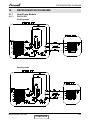
PNX 30 DCI
Cooling mode
Heating mode
SM GCD030 1-A.0 GB
10-1
CONTENTS
REFRIGERATION DIAGRAMS
10.2
Heat Pump Models
10.2.1
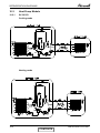
SX 30 DCI
Cooling mode
EEV
Heating mode
EEV
SM GCD030 1-A.0 GB
10-2
CONTENTS
REFRIGERATION DIAGRAMS
10.3
Heat Pump Models
10.3.1
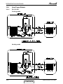
CKD 30 DCI
Cooling mode
EEV
Heating mode
EEV
SM GCD030 1-A.0 GB
10-3
CONTENTS
REFRIGERATION DIAGRAMS
10.4
Heat Pump Models
10.4.1
DLS 30 DCI
Cooling mode
EEV
EEV
Heating mode
EEV
EEV
SM GCD030 1-A.0 GB
10-4
CONTENTS
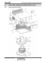
TUBING CONNECTIONS
11.
TUBING CONNECTIONS
TUBE (Inch)
¼”
⅜”
½”
⅝”
¾”
15-18
13-20
11-13
40-45
13-20
11-13
60-65
18-25
11-13
70-75
18-25
11-13
80-85
40-50
11-13
TORQUE (Nm)
Flare Nuts
Valve Cap
Service Port Cap
1.
2.
3.
4.
5.
6.
7.
8.
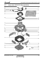
Valve Protection Cap-end
Refrigerant Valve Port (use Allen wrench to open/close)
Valve Protection Cap
Refrigerant Valve
Service Port Cap
Flare Nut
Unit Back Side
Copper Tube
When the outdoor unit is installed above the indoor unit an oil trap is required every 5m along the suction
line at the lowest point of the riser. Incase the indoor unit is installed above the outdoor, no trap is
required.
*Applicable for DLS18 only, for DLS24 – 44 oil traps are not required.
SM GCD030 1-A.0 GB
11-1
CONTENTS
CONTROL SYSTEM
12.
CONTROL SYSTEM
12.1
General Functions and Operating Rules
The DCI software is fully parametric.
All the model dependent parameters are shown in Blue color and with Italic style [parameter].
The parameters values are given in the last section of this control logic chapter of the service
manual.
12.1.1
System Operation Concept
The control function is divided between indoor and outdoor unit controllers. Indoor unit is the system
‘Master’, requesting the outdoor unit for cooling/heating capacity supply. The outdoor unit is the
system ‘Slave’ and it must supply the required capacity unless it enters into a protection mode
avoiding it from supplying the requested capacity.
The capacity request is transferred via indoor to outdoor communication, and is represented by
aparameter called ‘NLOAD’. NLOAD is an integer number with values between 0 and 127, and it
represents the heat or cool load felt by the indoor unit.
12.1.2
12.1.2.1
Compressor Frequency Control
NLOAD setting
The NLOAD setting is done by the indoor unit controller, based on a PI control scheme.
The actual NLOAD to be sent to the outdoor unit controller is based on the preliminary LOADcalculation,
the indoor fan speed, and the power shedding function.
NLOAD limits as a function of indoor fan speed:
12.1.3
12.1.3.1
Target Frequency Setting
Target Frequency Setting for GCD 030
During normal operation (excluding protections) the compressor target frequency is set according to
the ODU NLOAD number received from the indoor unit.
For single split channel the ODU NLOAD = IDU NLOAD
ODU NLOAD
Target Frequency [Hz]
0
0 < ODU NLOAD ≤ MinFreq
0
MinFreq
>MinFreq
MaxFreq MinFreq
{min (ODU NLOAD, LoadDeadZone) MinFreq} MinFreq
LoadDeadZone MinFreq
Refer to the following diagram for the above description:
SM GCD030 1-A.0 GB
12-1
CONTENTS
CONTROL SYSTEM
LoadDeadZone Seting:
Model P (DCI80)
Communication Channel
Cooling
127
90
Single Spit Channel
Multi Split Channel
12.1.4
Heating
127
127
Frequency Changes Control
When the unit is running normally , the compressor frequency change rate is 1 Hz/sec.
12.1.5
12.1.5.1
Compressor Starting Control
Compressor starting control for GCD 030
When started, compressor frequency must reach 30 Hz, and not go down below 30 Hz during the
first 5 minutes of compressor operation, except when compressor should be stopped (see next
sections for explanation).
When Reaching Step1Freq Hz and Step2Freq Hz (for the first time during one continuous compressor
operation) during compressor acceleration, compressor acceleration will be stopped for one minute
and then continue.
Note: If compressor is working constantly at a frequency between the step frequency and step
frequency – 10 Hz, then it will remain in its current frequency until one minute is over. After that
minute is over, there is no need to stop compressor acceleration again at the step frequency.
When compressor frequency is equal or higher than Step2Freq Hz, further increasing of compressor
frequency will be done in steps of HzDown1 Hz every one minute.
The Normal acceleration/deceleration rate will be kept during these steps.
Decelartion does not require steps.
The steps limitation is ignored during Deicing protection.
This logic should be followed every time frequency should be increased over Step2Freq, and not
only once.
Compressor frequency can not go over Step3Freq Hz during the first 10 minutes of continues
compressor operation (excluding Deicing).
12.1.6
Minimum On and Off Time
3 minutes
12.1.7
Indoor Fan Control
8 Indoor fan speeds are determined for each model. 4 speeds for cool/dry/fan modes and 4 speeds
for heat mode.
When user sets the indoor fan speed to a fixed speed (Low/ Medium/ High), unit will operate constantly
at set speed.
When Auto Fan is selected, indoor unit controller can operate in all speeds. The actual speed is set
according to the cool/heat load.
12.1.7.1
Turbo Speed
The Turbo speed is activated during the first 30 minutes of unit operation when auto fan speed is
selected and under the following conditions:
Difference between set point and actual room temperature is bigger then 3 degrees.
Room temperature > 22 for cooling, or < 25 for heating.
12.1.8
12.1.8.1
Outdoor Fan Control
Outdoor Fan Control for DCI 80 Z
OFAN operates between OFMinRPM to OFMaxRPM.
The OFAN will be off when the compressor is off.
when compressor is OFF, and HST>55 or faulty, OFAN will remain ON in 500 rpm for up to three
minutes.
IF HST falls below 55, OFAN will be switched off immediately.
12-2
CONTENTS
SM GCD030 1-A.0 GB
CONTROL SYSTEM
The fan speed level (to be set for h-com), is defined according to the following table:
OFAN Speed range
OFAN speed level
h-com
1 ~ 250
251 ~ 500
501~ 750
751 ~
Low
Med
High
Max
1
2
3
4
In cooling mode:
The OFAN speed is controlled according to the following objectives:
Mdoe
OFAN Target
Implementation
Cool Mode
Keep the condensation temperature
Keep OMT as low as possible down to 27°C.
to the minimum possible value
The following table describes the open loop of outdoor fan speed, at cool mode, related to the
outdoor air temperature and the frequency (ROM table):
Freq
~-10
0
80
160
250
300
350
0
20
40
60
80
100~
0
0
120
210
310
400
490
Outdoor air temperature (OAT)
10
20
30 or faulty
0
0
0
220
460
600
330
730
730
550
730
730
730
730
730
7 30 730
730
40
0
730
750
750
750
750
50~
0
730
750
750
750
750
In heating mode:
The outdoor fan will always be running at OFNNoiseMaxRPM during heating operation mode.
12.1.9
EEV (Electronic Expansion Vavle) Control
12.1.9.1
EEV Control for GCD 030
The target EEV value is the sum of open loop value (OL) and a result of the accumulative
correction values (CV).
EEV
EEVOL ¦ EEVCV
The EEV initial value (open loop) is determined according the following:
EEVOLi = EEVBase + EEVCpctyCrct + 0* EEVOATCrct + EEVFreqCrct
EEVBase
Base open loop
(Nominal Conditions/Capacity Code=1/MaxFrequency)
Single
Cool
250
Heat
200
SM GCD030 1-A.0 GB
12-3
CONTENTS
CONTROL SYSTEM
Correction by OAT (EEVOATCrct):
ODU Mode
EEVOATCrct
OAT
> 35
<=35
Faulty
>7
<=7
Faulty
Cool
Heat
Single Split
Multi Split
3*(OAT-35)
1*(OAT-35)
0
3*(OAT-7)
2*(OAT-7)
0
5*(OAT-35)
2*(OAT-35)
0
3*(OAT-7)
2*(OAT-7)
0
Correction by actual compressor frequency:
ODU Mode
EEVFreqCrct (Single)
EEVFreqCrct (multi)
Cool
-1*(MaxFreqC-Actual Frequency)
0*(MaxFreqC-Actual Frequency)
Heat
-1*(MaxFreqH-Actual Frequency)
0*(MaxFreqH-Actual Frequency)
The following table describes the time calculations for the Open loop and the Correction value:
EEV Open Loop
During BalanceTime
minutes after
compressor starts up
After BalanceTime minutes
Yes, continuously (always)
Yes, continuously (always)
Single
EEVCV
Yes, every EEVTime seconds from the last calculation point.
No (set to 0)
Multi
Yes, every EEVTime seconds from the last calculation point,
OR whenever the number of active IDUs is changed
For EEVTime parameter refer to the relevant each section described below.
12-4
CONTENTS
SM GCD030 1-A.0 GB
CONTROL SYSTEM
The following table represents the EEV correction according to the discharge superheat:
The discharge super heat correction for cooling mode (ROM table)
SHDischargeC
Der SHDischargeC
58~
56,57
54,55
52,53
50,51
48,49
46,47
44,45
42,43
40,41
38,39
36,37
~-5
10
8
6
5
4
3
2
1
0
-1
-2
-3
-4
12
10
8
6
5
4
3
2
1
0
-1
-2
-3
14
12
10
8
6
5
4
3
2
1
0
-1
-2
16
14
12
10
8
6
5
4
3
2
1
0
-1
18
16
14
12
10
8
6
5
4
3
2
1
34,35
-4
-3
-2
0
0
32,33
-4
-3
-2
0
0
30,31
28,29
26,27
24,25
22,23
20,21
-4
-4
-5
-5
-5
-6
-3
-3
-4
-4
-4
-5
-2
-2
-3
-3
-3
-4
-1
-1
-2
-2
-2
-3
0
0
-1
-1
-2
-2
18,19
-6
-5
-4
-3
-2
16,17
-6
-5
-4
-3
-2
14,15
12,13
10,11
8,9
6,7
4,5
2,3
~1
-7
-8
-9
-9
-10
-10
-10
-11
-6
-7
-8
-8
-9
-9
-9
-10
-5
-6
-7
-7
-8
-8
-8
-9
-4
-5
-6
-6
-7
-7
-7
-8
-3
-4
-5
-6
-6
-6
-6
-7
0
20
18
16
14
12
10
8
6
5
4
3
2
1
1
22
20
18
16
14
12
10
8
7
6
5
4
2
24
22
20
18
16
14
12
10
9
8
7
6
3
26
24
22
20
18
16
14
12
11
10
9
8
4
28
26
24
22
20
18
16
14
13
12
11
10
3
5
7
9
11
0
0
0
0
0
0
0
0
2
4
6
8
10
2
1
1
0
0
0
3
2
1
1
1
1
5
4
3
2
1
1
7
6
5
4
3
2
9
8
7
6
5
4
0
0
1
1
3
-1
-2
-3
-4
-5
-6
-6
-6
-6
-1
0
0
0
2
-1
-2
-3
-3
-4
-4
-4
-5
0
0
-1
-2
-2
-2
-2
-3
0
0
0
0
-1
-2
-2
-2
0
0
0
0
0
0
-1
-1
1
0
0
0
0
0
0
-1
SM GCD030 1-A.0 GB
5~
30
28
26
24
22
20
18
16
15
14
13
12
12-5
CONTENTS
CONTROL SYSTEM
The discharge superheat correction for heating mode (ROM table)
SHDischargeH
Der SHDischxargeH
57~
55,56
53,54
51,52
49,50
47,48
45,46
43,44
41,42
39,40
37,38
35,36
33,34
31,32
29,30
27,28
25,26
23,24
21,22
19,20
17,18
15,16
13,14
11,12
9,10
7,8
5,6
3,4
1,2
~0
12.1.10
~-5
12
10
8
6
5
4
3
2
1
0
-1
-2
-3
-4
-4
-4
-4
-5
-5
-5
-6
-6
-6
-7
-8
-9
-9
-10
-10
-10
-4
14
12
10
8
6
5
4
3
2
1
0
-1
-2
-3
-3
-3
-3
-4
-4
-4
-5
-5
-5
-6
-7
-8
-8
-9
-9
-9
-3
16
14
12
10
8
6
5
4
3
2
1
0
-1
-2
-2
-2
-2
-3
-3
-3
-4
-4
-4
-5
-6
-7
-7
-8
-8
-8
-2
18
16
14
12
10
8
6
5
4
3
2
1
0
0
0
-1
-1
-2
-2
-2
-3
-3
-3
-4
-5
-6
-6
-7
-7
-7
-1
20
18
16
14
12
10
8
6
5
4
3
2
1
0
0
0
0
-1
-1
-2
-2
-2
-2
-3
-4
-5
-6
-6
-6
-6
0
22
20
18
16
14
12
10
8
6
5
4
3
2
1
0
0
0
0
0
0
0
0
-1
-2
-3
-4
-5
-6
-6
-6
1
24
22
20
18
16
14
12
10
8
7
6
5
4
3
2
2
1
1
0
0
0
0
-1
-1
-2
-3
-3
-4
-4
-4
2
26
24
22
20
18
16
14
12
10
9
8
7
6
5
4
3
2
1
1
1
1
0
0
0
0
-1
-2
-2
-2
-2
3
28
26
24
22
20
18
16
14
12
11
10
9
8
7
6
5
4
3
2
1
1
1
0
0
0
0
0
-1
-2
-2
4
30
28
26
24
22
20
18
16
14
13
12
11
10
9
8
7
6
5
4
3
2
1
0
0
0
0
0
0
0
-1
5~
32
30
28
26
24
22
20
18
16
15
14
13
12
11
10
9
8
7
6
5
4
3
2
1
0
0
0
0
0
0
RV(Reversing Valve) Control
Reversing valve is on in heat mode.
Switching of RV state is done only after compressor is off for over 3 minutes.
12.1.11
Ioniser Control
Ioniser is on when unit is on ,AND indoor fan is on ,AND Ioniser power switch (on Ioniser) is on.
12-6
CONTENTS
SM GCD030 1-A.0 GB
CONTROL SYSTEM
12.1.12
Base Heater Control
The base heater will be working only when RV is “ON” according to the following graph:
Base
Heater
OFF
ON
0
2
OAT
When OAT is faulty the base heater will be “ON” continuously in HEAT mode.
12.2
Fan Mode
In high/ medium/ low indoor fan user setting, unit will operate fan in selected speed.
In AutoFan user setting, fan speed will be adjusted automatically according to the differencebetween
actual room temperature and user set point temperature.
12.3
Cool Mode
NLOAD is calculated according to the difference between actual room temperature and user set
point temperature by PI control.
In high/ medium/ low indoor fan user setting, unit will operate fan in selected speed.
In AutoFan user setting, fan speed will be adjusted automatically according to the calculated
NLOAD
12.4
Heat Mode
NLOAD is calculated according to the difference between actual room temperature and user set
point temperature by PI control.
In high/ medium/ low indoor fan user setting, unit will operate fan in selected speed.
In AutoFan user setting, fan speed will be adjusted automatically according to the calculated
NLOAD.
12.4.1
Temperature Compensation
In wall mounted, ducted, and cassette models, 3 degrees are reduced from room temperature
reading (except when in I-Feel mode), to compensate for temperature difference between high and
low areas in the heated room, and for coil heat radiation on room thermistor.
The temperature compensation can be enabled/disabled by shortening of J2 on the indoor unit
Controller
Model
J2 Shorted
J2 Opened
Wall mounted
Cassette
Compensation Disabled
Compensation Enabled
Compensation Enabled
Compensation Disabled
Ducted
Floor/Ceiling
Compensation Enabled
Compensation Disabled
Compensation Disabled
Compensation Enabled
SM GCD030 1-A.0 GB
12-7
CONTENTS
CONTROL SYSTEM
12.4.2
Indoor Fan Control in Heating Mode
Indoor fan speed depends on the indoor coil temperature:
12.5
Auto Cool/Heat Mode
When in auto cool heat mode unit will automatically select between cool and heat mode according
to the difference between actual room temperature and user set point temperature (.T). Unit will
switch from cool to heat when compressor is off for 3 minutes, and .T < -3.
Unit will switch from heat to cool when compressor is off for 5 minutes, and .T < -3.
12.6
Dry Mode
As long as room temperature is higher then the set point, indoor fan will work in low speed and
compressor will work between 0 and MaxNLOADIF1C Hz.
When the room temperature is lower than the set point, compressor will be switched OFF and indoor
fan will cycle 3 minutes OFF, 1 minute ON.
12.7
Protections
There are 5 protection codes.
Normal (Norm) – unit operate normally.
Stop Rise (SR) – compressor frequency can not be raised but does not have to be decreased.
HzDown1 (D1) – Compressor frequency is reduced by 2 to 5 Hz per minute.
HzDown2 (D2) – Compressor frequency is reduced by 5 to 10 Hz per minute.
Stop Compressor (SC) – Compressor is stopped.
12.7.1
Indoor Coil Defrost Protection
12.7.1
Indoor Coil Defrost Protection
ICT Trend
ICT
Fast
Increasing
Increasing
No Change
Decreasing
Fast
Decreasing
ICT< -2
-2 ≤ ICT<0
0 ≤ ICT < 2
2 ≤ ICT< 4
4 ≤ ICT < 6
6 ≤ ICT ≤ 8
ICT> 8
SC
D1
SR
SR
Norm
Norm
SC
D1
SR
SR
Norm
Norm
SC
D2
D1
SR
SR
Norm
Norm
SC
D2
D2
D1
SR
SR
SC
D2
D2
D2
D1
SR
12-8
CONTENTS
SM GCD030 1-A.0 GB
CONTROL SYSTEM
12.7.2
12.7.2.1
Indoor Coil Overheating Protection
Indoor Coil Overheating Protection
ICT Trend
ICT
Fast
Decreasing
Decreasing
No Change
Increasing
Fast
Increasing
ICT >62
60 ≤ ICT < 62
55≤ ICT <60
52≤ ICT < 55
48≤ ICT < 52
45≤ ICT ≤ 48
ICT <45
SC
D1
SR
SR
Norm
Norm
SC
D1
SR
SR
Norm
Norm
SC
D2
D1
SR
SR
Norm
Norm
SC
D2
D2
D1
SR
SR
SC
D2
D2
D2
D1
SR
12.7.2.2
Indoor Coil Overheating Protection
ICT
ICT Trend
<-2
-2
-1,0,1
2
>2
ICT >62
SC
SC
SC
SC
SC
60 ≤ ICT < 62
D1
D1
D2
D2
D2
58≤ ICT <60
SR
SR
D1
D2
D2
56≤ ICT < 58
SR
SR
SR
D1
D2
54≤ ICT < 56
Norm
Norm
SR
SR
D1
52≤ ICT ≤ 54
Norm
Norm
Norm
SR
SR
ICT <52
12.7.3
12.7.3.1
Norm
Compressor Overheating Protection
Compressor Overheating Protection for GCD 030
There are 4 control statuses for the protection: P1, P2, P3, Stop Compressor according to
the following chart.
CTT
105
100
95
90
Stop-Compressor
P3
P2
P1
Normal
SM GCD030 1-A.0 GB
12-9
CONTENTS
CONTROL SYSTEM
DerCTT = current CTT – CTT of last decision time point
Control Status
DerCTT>1 or when protection
Else
status is increased
P1
Normal
Stop Rise
P2
HzDown 1
Stop Rise
P3
HzDown 2
HzDown 1
Stop Compressor
Stop Compressor
12.7.4
Compressor Over Current Protection
CCR
Stop-Compresor
CCROC4
HzDown2
CCROC3
HzDown1
CCROC2
Stop-Rise
CCROC1
Normal
12.7.5
Heat Sink Overheating Protection
12.7.5.1
Heat Sink Overheating Protection For GCD 030
HSTn is the current reading of HST and HSTn-1 is the last reading of HST.
HSTn-HSTn-1
12.7.6
HSTn
<-1
HSTn ≥ 88
84 ≤ HSTn < 88
80 ≤ HSTn < 84
76 ≤ HSTn <80
72 ≤ HSTn <76
HSTn < 72
SC
D1
SR
SR
Norm
<0
≥ -1
SC
D1
SR
SR
Norm
>0
≤1
SC
D2
D2
D1
SR
0
SC
D2
D1
SR
Norm
Norm
>1
SC
D2
D2
D1
SR
Outdoor Coil Overheating Protection For GCD 030
OMTn is the current reading of OMT and OMTn-1 is the last reading of OMT.
OMTn
OMTn ≥ 66
64 ≤ OMTn < 66
62 ≤ OMTn <64
60 ≤ OMTn < 62
58 ≤ OMTn <60
OMTn < 58
OMTn-OMTn-1
<-1
-1
SC
D2
D1
SR
Norm
SC
D2
D1
SR
Norm
12-10
CONTENTS
0
SC
D2
D1
SR
Norm
Norm
1
>1
SC
D2
D1
SR
Norm
SC
D2
D1
SR
Norm
SM GCD030 1-A.0 GB
CONTROL SYSTEM
12.7.7
System Over Power Protection Only For GCD 030
A new control status will be set according to the following graph every 5 seconds
Powern is the current reading of system power and Powern-1 is the last reading of System Power.
Powern-Powern-1
Powern
<-50
[-50,-1]
0
[1,50]
>50
Powern > OVRPWR5
SC
SC
SC
SC
SC
OVRPWR4 ≤ Powern < OVRPWR5
D1
D1
D2
D2
D2
OVRPWR3 ≤ Powern < OVRPWR4
SR
SR
D1
D2
D2
OVRPWR2 ≤ Powern < OVRPWR3
SR
SR
SR
D1
D1
OVRPWR1 ≤ Powern < OVRPWR2
Norm
Norm
Norm
SR
SR
Powern < OVRPWR1
Norm
There are two sets of OVRPWR values, the selection of the values are set according to the state of
the Power-Shed input:
Variable
OVRPWR1 =
OVRPWR2 =
OVRPWR3 =
OVRPWR4 =
OVRPWR5 =
12.7.8
12..7.8.1
Parameter
Parameter
(Power Shedding input is open) (Power Shedding input is close)
3050
3150
3200
3300
3400
2300
2450
2600
2750
2900
Outdoor Coil Deicing Protection
Outdoor coil Deicing Protection For GCD 030
● Entering Deicing Conditions
Deicing operation will start when either one of the following conditions exist:
Case 1: OCT < OAT – 8 AND TLD > DI
Case 2: OCT < OAT – 12 AND TLD > 30 minutes.
Case 3: OCT is Invalid AND TLD > DI
Case 4: Unit is just switched to STBY AND OCT < OAT – 8
Case 5: NLOAD = 0 AND OCT < OAT -8
Case 6: OCT<-4 AND TLD>100 minutes
All this condition will exist during 10 seconds
OCT – Outdoor Coil Temperature
OAT – Outdoor Air Temperature
TLD – Time from Last Deicing
DI – Deicing Interval (Time Interval Between Two Deicing)
Deicing interval time when compressor is first started in heat mode, is 10 minutes if OCT < -2, and
is 40 minutes in other cases.
Deicing interval time is changed (increased/ decreased in 10 minutes steps) as a function of deicing
time. If deicing time is shorter then former deicing time, the deicing interval time will be increased. If
deicing time is longer then former deicing time, the deicing interval time will be decreased.
SM GCD030 1-A.0 GB
12-11
CONTENTS
CONTROL SYSTEM
●
Deicing Operation Procedure
T1=60 secondes;T2=36 secondes;T3=6 secondes
12.7.9
Condensate Water Over Flow Protection
Each of the pins P1, P2, P3 can have two options:
1 – When it is shorted with P4
0 – When it is not shorted to P4
Water Level Protection-1 level
●
P1
P2
P3
Level
Don’t care
Don’t care
1
Normal
Don’t care
Don’t care
0
Overflow
12-12
CONTENTS
SM GCD030 1-A.0 GB
CONTROL SYSTEM
Overflow when
unit is ON
Overflow
Water Level
Overflow when
unit is OFF
Normal
ON
OPER
LED
OFF
BLINK
ANY
NLOAD
NLOAD is
forced to 0
0
ON
PUMP
OFF
8 min
12.8
8 min
8 min
Indoor Unit Dry Contact
Indoor unit Dry contact has two alternative functions that are selected by J9.
Function
Contact=open
Contact=short
J9=open
Presence Detector
Connection
No limit
Force to STBY
J9=short
Power Shedding Function
No limit
Limit NLOAD
12.9
Operating the Unit from Mode Button
Forced operation allows to start, stop and operate in Cooling or Heating, in pre-set temperature
according to the following table:
Forced operation Mode
Pre-set Temperature
Cooling
20°C
Heating
28°C
12.10
Exceeding operation conditions For DCI 80Z
In order to protect the compressor from exceeding its normal operation range, the system will
behave according to the following whenever operation range is exceeded:
Exceeding limits state
Indoor Mode request
Cooling
Cooling
Heating
Heating
Outdoor conditions
A=47
B=-11
B=-18
A=30
Normal state (default)
0
1
0 (or OAT faulty)
Idle
Idle
Idle
Idle
Cooling
Cooling
Heating
Heating
SM GCD030 1-A.0 GB
Outdoor mode
Cool
Cool
Heat
Heat
12-13
CONTENTS
CONTROL SYSTEM
12.11
On Unit Controls and Indicators
12.11.1
Indoor Unit controller Controls and Indicatiors for All Models Except for
Floor/Ceiling model
During OFF, Fan, Cool, Heat, Dry, and Auto modes (for operation in other modes, see at the
relevant spec paragraph):
STAND BY
INDICATOR
1. Lights up when the Air Conditioner is connected to power
and ready to receive the R/C commands
OPERATION
INDICATOR
1. Lights up during operation.
2. Blinks for 300 msec., to announce that a R/C infrared
signal has been received and stored.
3. Blinks continuously during protections (according to the
relevant spec section).
TIMER INDICATOR
Lights up during Timer and Sleep operation.
FILTER INDICATOR
Lights up when Air Filter needs to be cleaned.
COOLING INDICATOR
Lights up when system is switched to Cool Mode by using the
Mode Switch on the unit.
HEATING INDICATOR
Lights up when system is switched Heat Mode by using the Mode
Switch on the unit.
Mode SWITCH
(COOL/HEAT/OFF)
Every short pressing , the next operation mode is selected, in this
order :
SB → Cool Mode → Heat Mode → SB → …
In long pressing system enters diagnostic mode.
For short pressing:
RESET / FILTER
SWITCH
When Filter LED is on - turn off the FILTER INDICATOR
after a clean filter has been reinstalled.
When Filter LED is off – enable/disable the buzzer
announcer, if selected.
In long pressing system enters set up mode (if in SB).
12.11.2
Outdoor Unit controller Indicatiors
Unit has three LED’s.
SB LED is ON when power is ON (230 VAC, even when no communication).
STATUS LED is ON when COMP is ON, and Blinks according to diagnostics mode definitions when
either fault or protection occurs.
FAULT LED Blinks according to diagnostics mode definitions when either fault or protection occurs.
12-14
CONTENTS
SM GCD030 1-A.0 GB
CONTROL SYSTEM
12.12
Jumper Settings
12.12.1
Indoor Unit Controller
0 = Open Jumper (disconnect jumper).
1 = Close Jumper (connect jumper).
Self test Jumper – J1
OPERATION
SELF-TEST
NORMAL
J1
1
0
Compensation Jumper – J2
Model
J2 (Default)
Compensation
0
1
1
Activated
Deactivated
Activated
PNX/PNX18/PNX30/WSA
SX/AC/NSX
LS/K/KS/AS/AD/DLS/KN
DLS series are defined by “family+ model”:
Family + model
KS+A
LS+A
KS+C
KS+D
J8
0
0
1
1
J7
0
0
0
1
Jumper setting
J6
0
0
0
0
J5
1
1
1
1
J4
0
1
0
0
J3
1
0
1
1
New family definition Model definition
DLS
DLS
DLS
DLS
A
B
C
D
Model selection Jumper – J7, J8
Model
J8
J7
A
B
C
D
0
0
1
1
0
1
0
1
J9- Presence Detector /Power Shedding
OPERATION
Presence Detector
Power Shedding
J9
0
1
Jumper – J10
OPERATION
PNX DCI LCD
LED
J10
0
1
SM GCD030 1-A.0 GB
12-15
CONTENTS
CONTROL SYSTEM
12.12.2
Outdoor Unit Controller
12.12.2.1 Outdoor Unit Controller For DCI80Z
JP9 Jumper Layout
ODU4 (PIN 9)
GND (PIN 10)
ODU3 (PIN 7)
GND (PIN 8)
ODU2 (PIN 5)
GND (PIN 6)
ODU1 (PIN 3)
GND (PIN 4)
ODU0 (PIN 1)
GND
(PIN 2)
ODU Model Selection
ODU4
ODU3
ODU2
ODU1
ODU0
ODU
Model
ON
ON
ON
ON
ON
ON
ON
ON
ON
ON
ON
ON
ON
ON
ON
ON
OFF
OFF
OFF
OFF
OFF
OFF
OFF
OFF
ON
ON
ON
ON
ON
ON
ON
ON
OFF
OFF
OFF
OFF
ON
ON
ON
ON
OFF
OFF
OFF
OFF
ON
ON
ON
ON
OFF
OFF
ON
ON
OFF
OFF
ON
ON
OFF
OFF
ON
ON
OFF
OFF
ON
ON
OFF
ON
OFF
ON
OFF
ON
OFF
ON
OFF
ON
OFF
ON
OFF
ON
OFF
ON
P (DCI80)
Q
R
S
T
U
V
W
X
Y
Z
AA
AB
AC
AD
AE
12.13
Test Mode
12.13.1
Entering Test Mode
Compressor Type
Single Split
Multi Split
Sanyo
Mitsubishi
System can enter Test mode in two ways:
Automatically when the following conditions exists for 30 minutes continuously:
Mode = Cool, Set point = 16, Room temperature = 27, Outdoor temperature = 35(+2/-1)
Or
Mode = Heat, Set point = 30, Room temperature = 20±1, Outdoor temperature = 7±(+1/-2)
Manually when entering diagnostics with the following settings:
Mode = Cool, Set point = 16
Mode = Heat, Set point = 30
12.13.2
Unit Operation in Test Mod
In test mode, the unit will operate in fixed settings according to the indoor fan speed setting:
Indoor FAN Speed Setting
Unit Setting
Low
Minimum Capacity Setting
Turbo
Auto
Nominal Capacity Setting
Maximum Capacity Setting
During test mode, protections are disabled, except for stop compressor status.
12-16
CONTENTS
SM GCD030 1-A.0 GB
CONTROL SYSTEM
12.14
SW Parameters
12.14.1
Indoor Units SW Parameters
Model dependent parametes - KLX
Cap .Group
NomLoadC
NomLoadH
MaxNLOADIF1C
MaxNLOADIF2C
MaxNLOADIF3C
MaxNLOADIF4C
MaxNLOADIF5C
MinRTC
MaxNLOADRTC
MaxNLOADIF1H
MaxNLOADIF2H
MaxNLOADIF3H
MaxNLOADIF4H
MaxNLOADIF5H
MaxNLOADRTH
MaxRTH
MaxNLOADPSC
MaxNLOADPSH
A
(KLX 24)
B
(KLX 30)
4
61
59
44
50
120
127
127
20
127
127
127
127
127
127
127
27
61
59
4
67
67
85
102
120
127
127
20
127
127
127
127
127
127
127
27
67
67
Model dependent parameters - DLS
Unit
Cap .Group
NomLoadC
NomLoadH
ICTSTSpeed
ICTVLSpeed
ICTLSpeed
ICTHSpeed
ICTTSpeed
MaxNLOADIF1C
MaxNLOADIF2C
MaxNLOADIF3C
MaxNLOADIF4C
MaxNLOADIF5C
MinRTC
MaxNLOADRTC
MaxNLOADIF1H
MaxNLOADIF2H
MaxNLOADIF3H
MaxNLOADIF4H
MaxNLOADIF5H
MaxNLOADRTH
MaxRTH
MaxNLOADPSC
MaxNLOADPSH
A
(DLS50)
B
(DLS60)
C
(DLS72)
D
(DLS80)
3
62
74
22
28
30
32
40
50
63
120
127
127
20
127
127
127
127
127
127
127
27
62
74
3
77
80
22
28
30
32
40
50
63
120
127
127
20
127
127
127
127
127
127
127
27
77
80
4
57
55
22
28
30
32
40
63
85
115
127
127
20
127
127
127
127
127
127
127
27
57
55
4
60
63
22
28
30
32
40
78
100
127
127
127
20
127
127
127
127
127
127
127
27
60
63
SM GCD030 1-A.0 GB
12-17
CONTENTS
CONTROL SYSTEM
Model dependent parameters - PNX
Parameter name
(PNX) Wall Mounted Models
25
35
50
60
72
80
53
68
NLOAD limits as a function of selected indoor fan speed
MaxNLOADIF1C
40
40
45
50
MaxNLOADIF2C
53
53
62
85
75
90
MaxNLOADIF3C
120
120
120
120
105
120
MaxNLOADIF4C
127
127
127
127
127
127
MaxNLOADIF5C
127
127
127
127
127
127
Indoor Fan speeds
IFVLOWC
700
700
700
800
850
850
IFLOWC
800
800
900
1000
1000
1000
IFMEDC
900
950
1050
1100
1150
1150
IFHIGHC
1050
1100
1200
1250
1350
1300
IFTURBOC
1150
1200
1250
1300
1400
1350
IFVLOWH
700
700
700
800
900
900
IFLOWH
800
850
900
950
1050
1050
IFMEDH
950
1000
1100
1150
1200
1200
IFHIGHH
1100
1150
1250
1250
1350
1300
IFTURBOH
1200
1250
1300
1300
1400
1350
Model dependent parameters - SX
A
(SX50)
B
(SX60)
C
(SX72)
D
(SX80)
Cap .Group
3
3
NomLoadC
68
80
NomLoadH
77
82
MaxNLOADIF1C
40
50
MaxNLOADIF2C
60
85
MaxNLOADIF3C
90
127
MaxNLOADIF4C
90
127
MaxNLOADIF5C
90
127
MinRTC
20
20
MaxNLOADRTC
127
127
MaxNLOADIF1H
127
127
MaxNLOADIF2H
127
127
MaxNLOADIF3H
127
127
MaxNLOADIF4H
127
127
MaxNLOADIF5H
127
127
MaxNLOADRTH
127
127
MaxRTH
27
27
MaxNLOADPSC
68
80
MaxNLOADPSH
77
82
4
60
60
127
127
127
127
127
20
127
127
127
127
127
127
127
27
60
60
4
63
67
127
127
127
127
127
20
127
127
127
127
127
127
127
27
63
67
Unit
12-18
CONTENTS
SM GCD030 1-A.0 GB
CONTROL SYSTEM
12.14.2
Outdoor Units SW Parameters
Model dependent parameters for GCD 030
#
1.
2.
3.
4.
5.
6.
7.
8.
9.
10.
11.
12.
13.
14.
15.
16.
17.
18.
19.
20.
21.
22.
23.
24.
25.
26.
27.
28.
29.
30.
31.
32.
33.
34.
35.
36.
37.
38.
39.
40.
41
42.
43.
44.
45.
46.
47.
48.
49.
50.
51
52.
53.
54.
55.
56.
57.
58.
59.
60.
61
62.
63.
64.
Name
MinFreqC
MaxFreqC
MinFreqH
MaxFreqH
LoadDeadZone
ODUCodeC
ODUCodeH
EEVBase
EEVCpctyCrct
Step1Freq
Step2Freq
Step3Freq
OFMinRPM
OFMaxRPM
NightRPM
OFNNoiseMaxRPM
CTTOH1
CTTOH2
CTTOH3
CTTOH4
CCROC1
CCROC2
CCROC3
CCROC4
EEVMinOperOpenC
EEVMaxOperOpenC
EEVMinOperOpenH
EEVMaxOperOpenH
EEVMinOperOpenHInactive
EEVMaxOperOpenHInactive
HeaterDisableFlag
NormAccel
NormDecel
OCTExitDeicer
MaxDeicerTime
EEVDecierOpenSingle
EEVDecierOpenMulti
DeicerCoef
EEV_Active_H_Isotherm
EEV_Active_H_SC
EEV_Active_H_SC_Crct
EnableExceedCond
OVRPWR1
OVRPWR2
OVRPWR3
OVRPWR4
OVRPWR5
OVRPWRPS1
OVRPWRPS2
OVRPWRPS3
OVRPWRPS4
OVRPWRPS5
OVRPWRTcnst
MinSumCapCode1
MinSumCapCode2
MinSumCapCode3
MinSumCapCode4
MaxSumCapCode1e
MaxSumCapCode2
MaxSumCapCode3
MaxSumCapCode4
Max_IDU_Number
InstTestCompSpeed
InstTestEEV
P
(DCI 80)
15
75
15
90
In Text
In Text
In Text
In Text
In Text
40
60
75
16
90
60
78
90
95
100
105
13.5
14
15.0
15.6
50
480
50
480
130
130
0
1
1
12
15
480
160
0.8
4
10
1
0
3050
3150
3200
3300
3400
2300
2450
2600
2750
2900
5
2
2
2
2
2
4
5
6
4
35
180
SM GCD030 1-A.0 GB
12-19
CONTENTS
TROUBLESHOOTING
13
TROUBLESHOOTING FOR GC030
WARNING!!!
When Power Up – the whole outdoor unit controller, including the wiring, is under
HIGH VOLTAGE!!!
Never open the Outdoor unit before turning off the Power!!!
When turned off, the system is still charged (400V)!!!
It takes about 1 Min. to discharge the system.
Touching the controller before discharging may cause an electrical shock!!!
For safe handling of the controller please refer to section 14.1.5 below
13.1
No
General System Failures and Corrective Actions
Symptom
Probable Cause
Corrective Action
No power supply
Check power supply. If OK,
check display and display
wiring. if OK, replace
controller
2
Indoor unit does not respond to
remote control message
Remote control
message not reached
the indoor unit
Check remote control
batteries, if OK, check
display and display wiring,
if OK, replace display
PCB. If still not OK replace
controller
3
Indoor unit responds to remote
control message but Operate
indicator (Green LED) does not
light up
Problem with display
PCB
Replace display PCB.
If still not OK replace
controller
Unit in heat mode and
coil is still not warm
Change to cool mode
Outdoor unit is in
opposite mode
Change operation mode
Problem with controller
or capacitor
Change to high speed
and Check power supply
to motor is higher than
130VAC (for triack
controlled motor) or higher
than 220VAC for fixed
speed motors, if OK replace
capacitor, if not OK replace
controller
5
Indoor fan works when unit is
OFF, and indoor fan speed is
not changed by remote control
command.
Controller problem
Replace controller
6
Water leakage from indoor unit
Indoor unit drainage
tube is blocked
Check and open drainage
tube
1
4
Indoor unit power supply indicator
(Red LED) does not light up.
Indoor fan does not start (louvers
are opened and Green LED is
ON)
SM GCD030 1-A.0 GB
13-1
CONTENTS
TROUBLESHOOTING
No
7
8
Symptom
Probable Cause
Outdoor unit display board and
leds are off
Compressor operates but no
capacity
No power supply
Check the connections
and the wiring on the main
terminal - Repair if needed.
PFC Chock coil
Check the PFC Chock coil
Burnt fuse
Check 20A fuse on the Filter
EEV problem
Check EEV
Refrigerant leakage
Check refrigeration system
Indoor coil block
Outdoor coil block
EEV problem
Refrigerant leakage
9
Compressor is over heated and
unit does not generate capacity
10
Compressor stops during
operation
11
Unit is not operating
Corrective Action
Indoor coil block
Clean filters and/or remove
block
Remove block and/or avoid
air by-pass
Check EEV
Check refrigeration system)
Clean filters and/or remove
block
Outdoor coil block
Remove block and/or avoid
air by-pass
Electronic control
Check diagnostics
Refrigerant leakage
Check refrigeration system
Communication
problems
Electronics control
problem or protection
Check diagnostics
12
Compressor does not start
13
Unit works in wrong mode (cool
instead of heat or heat instead of
cool)
Electronics or RV
problem
Check RV
14
All components are operating
properly but no cooling or no
heating
Refrigerant leak
Check refrigeration system
15
Compressor motor is generating
noise and no suction occurs
Phase order to
compressor is wrong
Check compressor phase
order
16
Freezing of outdoor unit in heat
mode and outdoor unit base is
blocked with ice
17
The unit stop suddenly during
operation
18
Indoor unit(s) Indicator(s) leds
may flicker
Connect base heater
EMC interference to the
A/C unit
13-2
CONTENTS
Check for EMC problems
SM GCD030 1-A.0 GB
TROUBLESHOOTING
No
Symptom
Probable Cause
21
Other home appliances operation
is faulty such as noise appears
EMC interference by
in the television picture, or the
the A/C unit
picture is distorted or static occurs
in the radio sound
22
All others
13.1.2
Specific problems of
indoor or outdoor units
Corrective Action
Check for EMC problems
Check diagnostics
Checking the refrigeration system
Checking system pressures and other thermodynamic measures should be done when system is
in technician Mode where the system operates as in fixed settings. The performance curves given
in this manual are given for unit performance in Technician mode when high indoor fan speed is
selected.
13.1.3
Diagnostics
13.1.3.1
Outdoor unit diagnostics
If any fault exists in the system, it will be shown according to tIf no fault exists in the system, no
fault code will be displayed during normal operation mode, and the status led will be on while the
compressor is enable.he following coding method.
Two LEDs display the system diagnostics on real time as follows:
STATUS LED is blinking 5 times in 5 seconds, and shut off for the next 5 seconds.
FAULT LED will blink during the same 5 seconds according to the following table:
13.1.3.1.1 LED’s Indicators - single split only
If any fault exists in the system, its fault will be shown according to the following coding method.
The last fault occurred in the system will be stored in the EEPROM.
If no fault exist in the system, no fault code will be displayed during normal operation mode.
When system enters diagnostics mode(through IDU communication), the last fault code will be displayed even
if the system has recover from that fault. The last fault will be deleted from the EEPROM after the system has
exit diagnostics mode (through IDU communication). The current system operation mode (cool/ heat/ off) will
not be changed when system enters diagnostics.
The coding method is as follow:
STATUS LED is blinking 5 times in 5 seconds, and shut off for the next 5 seconds.
FAULT LED will blink during the same 5 seconds according to the following table.
No
1
2
3
4
5
6
7
8
9
10
11
12
13
14
15
16
17
18
Problem
OCT is shorted/disconnected
CTT is shorted/disconnected
HST is shorted/disconnected
OAT is shorted/disconnected
OMT is shorted/disconnected
RGT is shorted/disconnected
RLT is shorted/disconnected
Reserved
Reserved
Reserved
Compressor IPM Fault / IPM Driver Pin / Compressor Current
Sensor Fault
Bad EEPROM
DC under voltage
DC over voltage
AC under voltage/AC over Voltage/Zero Crossing detection
Mismatch between IDU & ODU models
No Communication
System Over Power
SM GCD030 1-A.0 GB
AO
5
4
3
2
1
Yes
Yes
Yes
Yes
Yes
Yes
Yes
No
No
No
0
0
0
0
0
0
0
0
0
0
0
0
0
0
0
0
0
1
1
1
0
0
0
1
1
1
1
0
0
0
0
1
1
0
0
1
1
0
0
1
1
0
1
0
1
0
1
0
1
0
Yes
0
1
0
1
1
No
Yes
Yes
Yes
Yes
Yes
Yes
0
0
0
0
1
1
1
1
1
1
1
0
0
0
1
1
1
1
0
0
0
0
0
1
1
0
0
1
0
1
0
1
0
1
0
13-3
CONTENTS
TROUBLESHOOTING
No
19
20
21
22
23
24
25
26
27
28
29
30
31
Problem
PFC Current sensor
Heat sink Over Heating
Deicing
Compressor Over Heating
Compressor Over Current
No OFAN Feedback
OFAN IPM fault / OFAN IPM Driver Pin
Compressor Lock
Bad Communication
Missing ODU configuration
Undefined ODU Model
Outdoor/Indoor Coil Overheating
Operation conditions are exceeded
AO
5
4
3
2
1
Yes
No
No
No
No
Yes
Yes
Yes
No
Yes
Yes
No
Yes
1
1
1
1
1
1
1
1
1
1
1
1
1
0
0
0
0
0
1
1
1
1
1
1
1
1
0
1
1
1
1
0
0
0
0
1
1
1
1
1
0
0
1
1
0
0
1
1
0
0
1
1
1
0
1
0
1
0
1
0
1
0
1
0
1
1 – ON, 0 – OFF
Only one code is shown. Order of priority is 1-24. Diagnostics is continuously ON as long power is on.
13.1.3.1.2 ODU Alarm'
1. AO stands for 'Alarm Output
2. When a fault, marked with AO=Yes, occur, then the 'ODU Alarm' bit will be on. Otherwise it will be off.
3. For Faults that are marked with AO=No, even if these faults occur, then the 'ODU alarm' bit will be
always Off.
4. For the multi split units, whenever the outdoor looses communication with any indoor unit looses
communication, the alarm output will be on. When the communication is back it normal, the alarm
will be off.
No
Problem
5
4
3
2
1
1
2
3
4
5
6
7
11
13
14
15
16
17
18
19
24
25
26
28
29
31
OCT is shorted/disconnected
CTT is shorted/disconnected
HST is shorted/disconnected
OAT is shorted/disconnected
OMT is shorted/disconnected
RGT is shorted/disconnected
RLT is shorted/disconnected
Compressor IPM Fault / IPM Driver Pin / Compressor Current Sensor Fault
DC under voltage
DC over voltage
AC under voltage/AC over Voltage/Zero Crossing detection
Mismatch between IDU & ODU models
No Communication
System Over Power
PFC Current sensor
No OFAN Feedback
OFAN IPM fault / OFAN IPM Driver Pin
Compressor Lock
Missing ODU configuration
Undefined ODU Model
Operation conditions are exceeded
0
0
0
0
0
0
0
0
0
0
0
1
1
1
1
1
1
1
1
1
1
0
0
0
0
0
0
0
1
1
1
1
0
0
0
0
1
1
1
1
1
1
0
0
0
1
1
1
1
0
1
1
1
0
0
0
0
0
0
0
1
1
1
0
1
1
0
0
1
1
1
0
1
1
0
0
1
1
0
0
1
0
0
1
1
0
1
0
1
0
1
1
1
0
1
0
1
0
1
0
1
0
0
1
1
Notes:
1 - ON, 0 - OFF
Whenever this table is updated, the installation test procedure, and the alarm output function should be updated.
Only one code is shown.
Order of priority is 1-32. Diagnostics is continuously ON as long as power is on.
Heat Sink Over Heating Protection, Compressor Over Heating Protection, and System Over Power Protection are declared
only whenever in ‘Stop-Compressor’ status.
All faults, except the thermistor faults, will remain at least 10 seconds. This rule comes to serve the monitoring utilities, in
a case the fault is released quickly it will be still shown under the monitoring utilities.
Thermistor faults are reported only when they are enabled.
When the outdoor unit is in fault (not protection), an in-fault signal is sent to the indoor. When all the outdoor unit faults are
cleared, ‘no-fault’ signal is sent to the indoor.
13-4
CONTENTS
SM GCD030 1-A.0 GB
TROUBLESHOOTING
13.1.3.2
Outdoor fault corrective actions
No
Fault Name
1
OCT bad
2
CTT bad
3
HST bad
4
OAT bad
5
OMT bad
6
RGT bad
7
RLT bad
8
9
Fault Description
Corrective Action
Thermistor not connected or damaged
Check Thermistor (13.1.4.8)
Reserved
NA
NA
Reserved
NA
NA
10
11
Reserved
Compressor IPM Fault
/ IPM Driver Pin /
Compressor Current Sensor
Fault
NA
NA
PM module detect shoot-through current Disconnect the the compressor plug
/ IPM driver control pin is unconditionally and measure between U-V, U-W for
latch to high state /
resistance using multimeter. Resistance
The quiescent reference voltage of
value should be below 1 OHM. If
sensor resistor is either too high or too
multimeter display high resistance,
replace compressor. Make sure the
low.
phase sequence of U-V-W is correctly
plug into the compressor, othewise
replace controller if error is persistent
12
Bad EEPROM
Writing to EEPROM is impossible or
EEPROM IC is damage
13
DC under voltage
The capacitor bank DC voltage supply for Check AC input line voltage RMS value,
the compressor is below operable value it should read above 198VAC. If voltage
is above 198VAC, and DC under voltage
error is continuous display, replace
controller.
14
DC over voltage
The capacitor bank DC voltage supply for Check AC input line voltage RMS value,
the compressor is too high value
it should read below 264VAC. If voltage
is below 264VAC, and DC over voltage
error is continuously display, replace
controller.
15
AC under voltage/AC over
Voltage/Zero Crossing
detection
The AC input supply voltage is below
the limit of 198V / The AC input supply
voltage is above 264V / The AC line
frequency is out of range from 45Hz to
55Hz.
16
Mismatch between IDU &
ODU models
Miss-match between the IDUs connected Change configuration if needed.
to port A,B,C or D, or the total capacity
code of IDUs is higher than the ODU
maximum capacity code
17
18
No Communication
System Over Power
No signals in lineA,B,C,D
Compressor stopped due to over power
protection
Check communication (13.1.4.9)
No action required
19
PFC Current sensor
Controller cannot detect valid AC line
current after compressor start
If error is continuously being display,
replace controller.
20
Heat sink Over Heating
Compressor stopped due to heatsink
protection
Check that the airflow around the ODU
is free and the fan is running free. Check
fan motor (13.1.4.4)
SM GCD030 1-A.0 GB
There is no electrinonic corrective
action, just replace controller if error is
persistent.
Note: A/C still be able to operate, but
no event logging and mode restore on
power up
Check AC input line voltage RMS value,
it should read in the range of 198VAC –
264VAC. Check AC input line operating
frequency, it should be in the range from
45Hz to 55Hz. If error is continuously
being display, replace controller.
13-5
CONTENTS
TROUBLESHOOTING
No
Fault Name
Fault Description
Corrective Action
21
22
Deicing
Compressor Over Heating
During deicing procedure
Compressor stopped due to over heat
protection
No action required
Check if gas is missing in the system
23
Compressor Over Current
24
No OFAN Feedback
Compressor stopped due to over current No action required
protection
No encoder signal can be detected from Check DC-FAN hall sensor connection/
the OFAN
plug for damage. Check DC-FAN for any
blockage. Measure between U-V, U-W for
resistance using multimeter. Resistance
value should be below 1 OHM. If
multimeter display high resistance,
replace DC-FAN motor, otherewise
replace controller.
25
OFAN IPM fault / OFAN
IPM Driver Pin
OFAN IPM module detect shoot-through
current / OFAN IPM driver control pin is
unconditionally latch to high state
Check DC-FAN hall sensor connection/
plug for damage. Check DC-FAN for any
blockage. Measure between U-V, U-W for
resistance using multimeter. Resistance
value should be below 1 OHM. If
multimeter display high resistance,
replace DC-FAN motor. Return controller
if error is persistent.
26
Compressor Lock
No correct drive current can be detected
from the compressor
Check compressor cable or compressor
wire assembly. Make sure the phase
sequence of U-V-W is correctly plug into
the compressor.
27
Bad Communication
Lost of communication from indoor unit
Check communication wire between
indoor and outdoor unit
28
Missing ODU configuration
All the DIP is set to 0 (the DIP are not
configured).
This problem cannot happen in DCI80.
Previously, this fault is used to detect
model plug that fall down.
29
Undefined ODU Model
The outdoor model is not defined in the
software.
30
Outdoor/Indoor Coil
Overheating
31
Operation conditions are
exceeded
Wrong Outdoor DIP setting.
Too old outdoor software. Update
software
Improper ventilation of the coils
This protection combines the following:
Over charged system
1.
Overheating in cooling mode (based
on OMT reading).
Problem with ICT sensors or OMT
2.
Overheating in heating mode based
sensor (fake up).
on ICT.
Illegal too small indoor unit’s
installation (heating).
For cooling:
This is not a fault but information on the
ambient operation:
The unit operates outside the defined
operation range.
The OAT fakes and cause false alarm.
For Heating:
13-6
CONTENTS
SM GCD030 1-A.0 GB
TROUBLESHOOTING
13.1.3.3
Fault Code for Indoor unit
Pressing Mode button for long will activate diagnostic mode by the acknowledgment of 3 short beeps
and lighting of COOL and HEAT LED’s.
Entering diagnostics in STBY mode allows only viewing of status (fault-display).
In diagnostic mode, system problems / information will be indicated by blinking of Heat & Cool
LED’s.
The coding method will be as follows:
Heat led will blink 5 times in 5 seconds, and then will be shut off for the next 5 seconds. Cool Led will
blink during the same 5 seconds according to the following table:
No
Fault Name
5
4
3
2
1
1
RT-1 is disconnected
0
0
0
0
1
2
RT-1 is shorted
0
0
0
1
0
3
RT-2 is disconnected
0
0
0
1
1
4
RT-2 is shorted
0
0
1
0
0
…
Reserved
0
0
1
0
1
7
Communication mismatch
0
0
1
1
1
8
No Communication
0
1
0
0
0
9
No Encoder
0
1
0
0
1
10
Reserved
0
1
0
1
0
11
Outdoor Unit Fault
0
1
0
1
1
…
Reserved
17
Defrost protection
1
0
0
0
1
18
Deicing Protection
1
0
0
1
0
19
Outdoor Unit Protection
1
0
0
1
1
20
Indoor Coil HP Protection
1
0
1
0
0
21
Overflow Protection
1
0
1
0
1
…
Reserved
24
EEPROM Not Updated
1
1
0
0
0
25
Bad EEPROM
1
1
0
0
1
26
Bad Communication
1
1
0
1
0
27
Using EEPROM data
1
1
0
1
1
28
Model A
1
1
1
0
0
29
Model B
1
1
1
0
1
30
31
Model C
Model D
1
1
1
1
1
1
1
1
0
1
1 - ON,
0 - OFF
Only one code is shown. Order of priority is lower to the higher number. Diagnostics is continuously
ON as long power is on.
SM GCD030 1-A.0 GB
13-7
CONTENTS
TROUBLESHOOTING
13.1.3.4
No.
Indoor unit diagnostics and corrective actions
Fault
Probable Cause
Corrective Action
1-4
Sensor failures
Sensors not connected or
damaged
Check sensor connections
or replace sensor
7
Communication
mismatch
Indoor and Outdoor controllers
are with different versions
Replace Indoor controller
8
No Communication
Communication or grounding
wiring is not good
Check Indoor to Outdoor
wiring and grounding
9
No Encoder
Indoor electronics or motor
Check motor wiring, if ok,
replace motor, if still not ok,
replace Indoor controller.
11
Outdoor Unit Fault
Outdoor controller problem
Switch to Outdoor
diagnostics.
Protections
Indication
No action
EEPROM Not
Updated
System is using ROM
parameters and not EEPROM
parameters
No action, unless special
parameters are required for
unit operation.
17-21
24
No action, unless special
parameters are required for
unit operation.
25
Bad EEPROM
26
Bad Communication
Communication quality is low
reliability
27
Using EEPROM data
No problem
28-31
Check Indoor to Outdoor
wiring and grounding
IDU model
13.1.4
Procedures for checking Main Parts
13.1.4.1
Checking Mains Voltage
Confirm that the Mains voltage is between 198 and 264 VAC. If Mains voltage is out of this range,
abnormal operation of the system is expected. If in range check the Power (Circuit) Breaker and look
for broken or loosed cable lugs or wiring mistake(s).
13.1.4.2
Checking Main fuse
Check 20A fuse on the Filter Board - If burnt – check the compressor, fan or any other peripheral that
can cause a short. In case of a problematic peripheral - replace it.
In case no problematic peripheral, check the resistance on the DC bank (B+ & B- on the Power
board), if it is less than 30Ω, replace the controller. Otherwise replace the burnt fuse. In case of
frequent burning fuse, replace the controller.
13.1.4.3
Checking PFC Chock coil
Check PFC chock connection – repair if needed.
Dis-connect the chock from the controller wire extensions, check if the 2 wires of the chock are
shorted. If shorted (OK) check between each wire and the metal box. If shorted replace chock, if
not (OK), open the controller top cover and check if the wire extensions are connected well and if
shorted. If not shorted, replace wires, if shorted (OK) than might be a controller problem – replace
controller.
13-8
CONTENTS
SM GCD030 1-A.0 GB
TROUBLESHOOTING
13.1.4.4
Checking the Outdoor Fan Motor
Check FAN-Power and FAN-Halls connections - Repair if needed.
Rotate the fan slowly by hand. If the fan does not rotate easily, check whether something is obstructing
the fan, or if the fan itself is coming into contact with the outer case, preventing it from rotating.
Correct if necessary - otherwise, the fan motor bearings have seized. Replace the motor.
If the fan rotates easily, use a current probe (“Clamp”) to assure AC current on each phase and it is
less than 1A.
In case there is no current, check the resistance between the three poles. Assure the three coil
resistances are almost the same.
The normal value should be between 10Ω to 20Ω.
Change to Stand-by or Power OFF and re-start - If the fault is still active - replace controller.
13.1.4.5
Checking the Compressor
Check Compressor connections - Repair if needed.
Use a current probe (“Clamp”) to assure that there is an AC current on each phase – no more than
15A.
In case there is no current, check the resistance between the three poles. Assure the three coil
resistances are almost the same (between 0.8Ω to 1.5Ω).
Change to Stand-by or Power OFF and re-start - If the fault is still “Active” - replace controller.
13.1.4.6
Checking the Reverse Valve (RV)
The RV has two parts, Solonoid and valve.
Solonoid - Running in heating mode, check the voltage between two pins of reverse valve connector,
normal voltage is 230VAC. if no power supply to RV, Check RV operation with direct 230VAC power
supply, if OK, replace outdoor controller.
Valve - if RV solonoid is OK (as above) but still no heating operation while compressor is On, replace
the valve.
13.1.4.7
Checking the electrical expansion valve (EEV)
The EEV has two parts, drive and valve.
When Outdoor unit is powered on, EEV shall run and have click and vibration.
For assuring the problem is of the EEV parts, perform the installation test and if fails and no other
indications in the diagnostics, than the problem is with the EEV (one or more).
Drive - a step motor; ringed on the valve. Check the drive voltage, should be12VDC.
Valve – if drive is OK (as above) but still the indoor unit perform no conditioning replace the valve (no
need to take out the refrigerant, just pump down and shut off the main valves).
13.1.4.8
Checking the termistors
Check Thermistor connections and wiring - Repair if needed.
Check Thermistor resistance – between 0ºC and 40ºC should be between 35KΩ and 5KΩ.
13.1.4.9
Checking the communication
Change to Stand-by or Power OFF and re-start - If the fault is still “Active” check Indoor to Outdoor.
Communication wiring and grounding connections (should be less than 2.0Ω) - Repair if needed.
If IDU failure – replace IDU controller that does not respond.
If ODU failure – replace ODU.
SM GCD030 1-A.0 GB
13-9
CONTENTS
TROUBLESHOOTING
13.1.4.10 Checking for electromagnetic interferance (EMC problems)
13.1.4.10.1 EMC troubles to the A/C unit
Locations most susceptible to noise :
1. Locations near broadcast stations where there are strong electromagnetic waves.
2. Locations near amateur radio (short wave) stations.
3. Locations near electronic sewing machines and arc-welding machines.
Trouble :
Either of the following trouble may occur:
1. The unit may stop suddenly during operation.
2. Indicator lamps may flicker
Correction :
The fundamental concept is to make the system less susceptible to noise
(insulate for noise or distance from the noise source):
1. Use shielded wires.
2. Move unit away from the noise source.
13.1.4.10.2 EMC troubles to near by home appliances
Locations most susceptible to noise :
1. A television or radio is located near the A/C and A/C wiring.
2. The antenna cable for a television or radio is located close to the A/C and A/C wiring.
3. Locations where television and radio signals are weak.
Trouble :
1. Noise appears in the television picture, or the picture is distorted.
2. Static occurs in the radio sound.
Correction
1. Select a separate power source.
2. Keep the A/C and A/C wiring at least 1 meter away from wireless devices and antenna
cables.
3. Change the wireless device’s antenna to a high sensitivity antenna.
4. Change the antenna cable to a BS coaxial cable.
5. Use a noise filter (for the wireless device).
6. Use a signal booster.
13.1.5
Precaution, Advise and Notice Items
13.1.5.1
High voltage in Outdoor unit controller
Whole controller, including the wires, connected to the Outdoor unit controller may have the potential
hazard voltage when power is on. Touching the Outdoor unit controller may cause an electrical
shock.
Advise: Don’t touch the naked lead wire and don’t insert finger, conductor or anything else into the
controller when power is on.
13.1.5.2
Charged Capacitors
Three large-capacity electrolytic capacitors are used in the Outdoor unit controller. Therefore,
charging voltage (380VDC) remains after power down. Discharging takes about one minute after
turned off. Touching the Outdoor unit controller before discharging may cause an electrical shock.
When open the Outdoor unit controller cover, don’t touch the soldering pin by hand or by any
conductive material.
13-10
CONTENTS
SM GCD030 1-A.0 GB
TROUBLESHOOTING
13.1.6.
Advise:
Open the Outdoor unit controller cover only after one minute from power off.
Measure the electrolytic capacitors voltage before farther checking controller.
Additional advises
When disassemble the controller or the front panel, turn off the power supply.
When connecting or disconnecting the connectors on the PCB, hold the whole housing, don’t pull the
wire, there are sharp fringes and sting on shell. Use gloves when disassemble the A/C units.
SM GCD030 1-A.0 GB
13-11
CONTENTS
EXPLODED VIEWS AND SPARE PARTS LISTS
14.
EXPLODED VIEWS AND SPARE PARTS LISTS
14.1
Indoor Unit: DLS 30 DCI
SM GCD030 1-A.0 GB
14-1
CONTENTS
EXPLODED VIEWS AND SPARE PARTS LISTS
14.2
No.
Indoor Unit: DLS 30 DCI
Part No. Description
Qty
1
473419
IU COIL GR/HDR
1
2
473231
FLOAT SUPPORT
1
3
473900
DLS METAL FILTER
1
4
473246
INSULATED DRAIN POOL ASSY
1
5
473700
DLS OVER FLOW SWITCH
1
6
473210
COIL SUPPORT
1
7
433605
DCI IDU CONTROL BOX
1
8
402713
WIRED DISPLAY BOX EMD/ELD
1
9
473905
FAN HOUSING ASSY
1
11
473248
AIR FILTER FRAME ASSY
1
12
473250
MOTOR LEG ASSY
3
16
436673
REMOTE CONTROL RC4/RC
1
17
430535
TERMINAL BLOCK P6/90
1
18
442019
CAPACITOR 8mF 400V P1/P2
1
19a
473720
THERMISTOR+CAP WITH CONNECTOR
1
19b
473710
THERMISTOR WITH CONNECTOR L235
1
7a
402730
CABLE 8 WIRES 7M WITH CONNECTOR
1
9a
473007
MOTOR
1
9b
473300
CENTRIFUGAL FAN DLS300/100
1
28
473415
ELECTRICAL COVER
1
14-2
CONTENTS
SM GCD030 1-A.0 GB
EXPLODED VIEWS AND SPARE PARTS LISTS
14.3
Indoor Unit: PNX 30 DCI
SM GCD030 1-A.0 GB
14-3
CONTENTS
EXPLODED VIEWS AND SPARE PARTS LISTS
14.4
No.
1
2
3
4
5
6
7
8
9
10
11
12
13
14
15
16
17
18
19
20
21
22
23
24
25
26
27
28
29
30
31
32
33
34
35
36
37
38
39
40
41
Indoor Unit: PNX 30 DCI
Part No.
4525902
4523299
4523303
4518113
4525610
4523301
4523302
462350007
4525112
4525612
4524962
4524965
4518664
4516204
4524954
4525611
433133
4523306
4523307
4524967
4523372
4523309
4525111
433134
453109300
4523311
4524953
4523313
4523312
4524661
4524961
4524966
4523308
4525113
438082
4519813
4525831
453161200
4516263
4524963
4523304
4523300
Description
GRILLE ASSY
FILTER
SHAFT LOCKER
AIR FILTER ASSY
FRAME ASSY
SCREW COVER
FIX LOCKER
EVAPORATOR ASSY PNX80 R410A
DISPLAY ASSY. 901-255-30
AIR OUTLET ASSY
TEP MOTOR B
STEP MOTOR WIRE A
DRAIN HOSE
BEARING ASSY.,FAN
CROSS FAN
REAR PANEL ASSY
IONIZER DISPLAY
IONIZER COVER(NO IONIZER)
IONIZER WIRE COVER(WITH IONIZER)
IONIZER WIRE A
PNX-30 INSTALLATION PLATE
TUBE OUTLET
REMOTE CONTROL BOX 974-700-00
IONIZER POWER
IONIZER CABLE B
MOTOR HOUSING
FAN MOTOR
MOTOR WATER BREAKER
MOTOR COVER
FIX PLATE
STEP MOTOR A
STEP MOTOR WIRE B
WATER BREAKER COVER
POWER CORD CABLE(optional)
THERMISTOR INDOOR COIL BACK
THERMISTOR ROOM BLACK
WIRE TUBE
CONTROL BOX 916-514-00
SENSOR BASE
ESF (optional)
WIRING COVER
FILTER R
14-4
CONTENTS
Quan.
1
1
2
1
1
3
4
1
1
1
2
1
1
1
1
1
1
1
1
1
1
1
1
1
1
1
1
1
1
1
1
1
1
1
1
1
1
1
1
1
1
1
SM GCD030 1-A.0 GB
EXPLODED VIEWS AND SPARE PARTS LISTS
14.5
Indoor Unit: SX 30 DCI
SM GCD030 1-A.0 GB
14-5
CONTENTS
EXPLODED VIEWS AND SPARE PARTS LISTS
14.6
Indoor Unit: SX 30 DCI
No.
Part No.
Description
Qty
1
484002
Grille
1
2
221554
Air Filter
2
3
373244
Right panel
1
4
307982
Frame Asy
1
5
371071-72
Display panel
1
6
470680004
Evaporator Assy
1
7
370280
Air Outlet Assy
1
8
285032
Draining Hose
1
9
372336
Horizontal louver front
1
9
372337
Horizontal louver back
1
10
371255
Vert. Louver
12
11
372340
Fan cover
1
12
293322
Fan
1
13
307980
Back panel
1
14
466236
Installation Plate
1
15
382333
Base panel EPS
1
16
466100005
Motor
1
17
323422
Motor support
1
18
436665
Step Motor
1
18
263034
Swing motor
1
20
455000603
Capacitor
1
21
234213
Display
1
22
373246
Fan frame
1
23
452935900
DCI storm
1
24
438082
Thermistor indoor coil
1
25
438413
Thermistor
1
26
311036
Storm panel
1
27
391508
DConnect wire
1
29
436609R
Remote control
1
30
373245
Left panel
1
33
4521029
Spring clip
1
14-6
CONTENTS
SM GCD030 1-A.0 GB
EXPLODED VIEWS AND SPARE PARTS LISTS
14.7
Indoor Unit: CKD 30 DCI (Exploded Unit’s)
30
31
35
27
5
25
33
23
4
57
10
41
42
12
51
6
52
24
3
50
7
8
49
20
62
26
54
19
16
22
43
53
40
28
29
SM GCD030 1-A.0 GB
14-7
CONTENTS
EXPLODED VIEWS AND SPARE PARTS LISTS
14.8
Indoor Unit: CKD 30 DCI (Exploded panel’s)
14-8
CONTENTS
SM GCD030 1-A.0 GB
EXPLODED VIEWS AND SPARE PARTS LISTS
14.9
No.
1
2
3
4
5
6
7
8
9
10
11
12
13
14
16
17
18
19
20
21
22
23
24
25
26
27
29
30
31
33
35
34
34
36
39
40
41
42
43
49
50
51
52
53
54
57
58
59
60
61
62
63
64
Outdoor Unit: CKD 30 DCI
Item
Description
P0000371694
P0000371695
202301300044
201109990016
202401100017
201552390005
202400610001
202742000006
P0000146588
202242800075
P0000402822
201142000601
P0000146552
P0000146553
202400410850
P0000146543
202400100007
201142000002
201242000605
467300128R
201242800078
467300222R
4523277
4523278
202242800076
201242800091
467200012R
201242800085
201242800084
202301450029
4523162
P0000146568
P0000146569
P0000146557
P0000146556
201242500081
201242800082
201102020216
201242800081
201652390017
201652390018
201242800086
201242800087
202742000002
201242000008
201142690001
P0000146558
P0000146559
P0000146560
P0000146561
201242000013
P0000146555
P0000146594
Grill/Airwell
Filter /CKD
Water-Level Switch Assy.
Front Panel/Airwell
Capacitor For Fan Motor 3.5uF
Evaporator Assy./CKD80
Pump
Drain Pipe
Flap
Drain Pan Assy
Display Cover
Centrifugal Fan
EPS 1 / Front Frame
EPS 2 / Front Frame
Motor/Indoor Unit
Front Frame
Step Motor
Connecting Pipe/Drain Pipe
Fixing Plate/Pump Assy.
Display Board/CN
Connection Support
Controller/ DCI KN new
ICT SENSOR
RW SENSOR
EPS/Air Housing Assy.
Electric Control Box Welded Assembly
Remote Controller
Cover I/Electric Control Box
Cover II/Electric Control Box
Terminal Block(6 Pole)
Transformer ASSY.
Grill Clasp Switch 1
Grill Clasp Switch 2
Cover /Front Plate
Flap Swing Assy.
Plate/Wire
Tandem/Wire
Bipitch Wire Clip
Base Pan Welded Assembly
Liquid Pipe Assy.
Gas Pipe Assy./CKD80
Fixing Plate/Evaporator
Hook/Evaporator
Cushion Rubber/Pump
Fan Fixer
Air Intake Assy.
Cover1 /Front Plate
Cover2 /Front Plate
Cover3 /Front Plate
Cover4 /Front Plate
Grommet/Drain Pipe
Hook Assy.
Support/Step Motor
SM GCD030 1-A.0 GB
Quan.
1
1
1
1
1
1
1
1
4
1
1
1
4
4
1
1
2
1
1
1
1
1
1
1
1
1
1
1
1
1
1
1
1
4
1
1
1
1
1
1
1
1
3
3
1
1
1
1
1
1
1
4
2
14-9
CONTENTS
EXPLODED VIEWS AND SPARE PARTS LISTS
14.10
Outdoor Unit: GCD 030
14-10
CONTENTS
SM GCD030 1-A.0 GB
EXPLODED VIEWS AND SPARE PARTS LISTS
14.11
NO.
1
2
3
4
5
6
7
8
9
10
11
12
13
14
15
16
17
18
19
20
21
22
23
24
25
26
27
28
29
30
31
32
33
34
35
36
37
38
39
40
Outdoor Unit: GCD 030
Item
Description
465100000
4523652
4523758
452960400
461600023
461030003
4526522
466110008R
4522601
4523653
467400200
467400040
452677601
452809900
460080000R
452783600
452783200
453256100
4526080
4526513
4526514
464080007
4522602
4518950
464250093
204107
467300185R
464280003
4526215
4526216
462300002
453175500
453083800
467550002R
464730010
467300184R
452888500
4523657
4522600
465120013
Grill/ DCI Trio
PAINTED LEFT CABINET ASSY
Nut M8 left
Outdoor Fan
4-Way Valve Assy.
4-way Valve Coil
FOUR-WAY VALVE R410A
DC Resin Motor
Right Handle
PAINTED RIGHT CABINET ASSY
Compressor Top Thermistor(CTT)
Condenser Middle Temperature Sensor/OAT & OMT
Outdoor Coil Thermistor(OCT)
Base Plate Painting Assy.
Compressor Assy./ C-7RVN153H0W SANYO ShenYang)
Oil Separator Assy.
Liquid-gas Separator
Support Painting Support Assy./Gas-Liquid Separator
Valve plate paint assy
LOW PRESS VALVE (R410A)
Hight press valve(R410A)
Right-Rear Plate/DCI 80 CR
Valve Cover
Filter Drier BFK-053S
Protecting Plate /controller
Cable clip Nylon
Controller / DCI 80 CR Filter Board
Terminal Plate/ DCI 80Z
Electronic expansion valve ZDPF(L)-1.6C-01-RK for R410A
EEV COIL QA(L)12-MD-02
Condenser Assy.
Guard Net Painting Assy.
Support/OAT
Choke / DCI 80 CR
Partition Plate Assy./DCI 80Z
Controller / DCI 80 CR OUTDOOR BOX ASSY
Motor Support
PAINTED TOP COVER ASSY
Left Handle
Air Outlet Cover/DCI 80 CR R410a
SM GCD030 1-A.0 GB
Quan.
1
1
1
1
1
1
1
1
1
1
1
1
1
1
1
1
1
1
1
1
1
1
1
1
1
2
1
1
1
1
1
1
1
1
1
1
1
1
1
1
14-11
CONTENTS
APPENDIX A
APPENDIX A
INSTALLATION AND OPERATION MANUAL
►
INSTALLATION AND OPERATION MANUAL GCD 030
SM GCD030 1-A.0 GB
15-1
CONTENTS