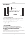
1
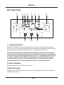
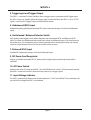
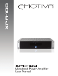
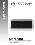
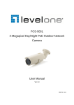
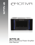
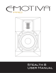
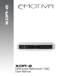
®
®
CLASS
A
A/B
®
STANDBY
Differential Reference™ Monoblock
Power Amplifier
User Manual
Important Safety Precautions and Explanation of Symbols
!
The exclamation point within an equilateral triangle is intended to alert the user to the presence of
important installation, operation, and service instructions in this manual.
The lightning flash with arrowhead symbol within an equilateral triangle is intended to alert the user to the
presence of uninsulated dangerous voltages within the enclosure that may be of sufficient magnitude to
constitute a risk of electrical shock to the user.
Please read this manual thoroughly before attempting to install, configure, or operate the XPA-1 power
amplifier. After successful installation and configuration of the XPA-1, be sure to retain this manual in a safe
place for future reference.
Safety is a key component to a long lasting and trouble free installation. Please read and follow all
instructions and heed all warnings on the XPA-1 and in this manual. The vast majority of the subsequent
safety precautions are common sense. If you are not comfortable with the installation of audio/video
entertainment equipment, you should seek the services of a qualified installation professional or call us for
help.
!
WARNING: TO REDUCE THE RISK OF FIRE OR ELECTRIC SHOCK, DO NOT USE THE XPA-1 NEAR WATER
OR IN WET LOCATIONS, DO NOT EXPOSE IT TO RAIN OR MOISTURE, DO NOT EXPOSE IT TO DRIPPING
OR SPLASHING FROM OTHER SOURCES, AND ENSURE THAT NO OBJECTS FILLED WITH LIQUIDS (SUCH
AS VASES) ARE PLACED ON IT. DOING SO MAY RESULT IN DAMAGE TO THE UNIT AND THE RISK OF
ELECTRIC SHOCK, WHICH MAY RESULT IN BODILY INJURY OR DEATH.
WARNING: TO REDUCE THE RISK OF ELECTRIC SHOCK, DO NOT REMOVE THE COVER FROM THE
XPA-1. THERE ARE NO USER-SERVICEABLE PARTS INSIDE THE UNIT. REFER ALL SERVICE TO QUALIFIED
SERVICE PERSONNEL.
Do not install the XPA-1 near or above any heat sources such as radiators, heating vents, or other apparatus’
that produce heat. Do not block any ventilation openings or heat sinks. Avoid installing the unit directly
above other heat-producing equipment unless sufficient ventilation or forced-air cooling is provided.
Do not install the XPA-1 in locations without proper ventilation. The XPA-1 should not be operated on a bed,
sofa, rug, or similar surface that may block vents. The unit should not be installed in an enclosed location
such as a bookcase, cabinet, or closed equipment rack unless sufficient forced-air ventilation is provided.
Always install your XPA-1 according to the manufacturer’s instructions and only use attachments or
accessories specified by the manufacturer.
Do not install the XPA-1 on any stand, shelf, or other piece of furniture that is unable to support its weight.
If a cart is used to move the unit, use caution to avoid injury from tip-over.
Connect the XPA-1 only to power sources of the correct voltage (as shown in this manual and on the
XPA-1 unit).
Protect power supply cables from being pinched, walked on, or otherwise damaged. Be especially careful
where the power cable enters the power outlet and the unit.
Only connect the XPA-1 to an electrical outlet or extension cord of appropriate type and rating.
DO NOT defeat the safety purpose of a grounding or polarized plug by removing ground pins or using
unsafe adapters. A polarized plug has two blades - one wider than the other. A grounding plug has a
third ground prong in addition to the two main conductors. The wide blade or third groundling prong is
provided for your safety. If the provided plug does not fit your outlet, consult an electrician to replace your
obsolete outlet. If you replace the power cord, only use one of similar type and equal or greater current
rating.
The power cable for the XPA-1 should be unplugged from the outlet during severe electrical storms, or
when unused for a long period of time.
Only replace the fuse(s) in the XPA-1 with fuse(s) of proper value and voltage rating.
The XPA-1 should only be cleaned as directed in the manual. Avoid spraying liquids directly onto the unit and
NEVER spray liquids into the vents. Care should be taken so that small objects do not fall into the inside of the
unit.
!
You should seek service for your XPA-1 by qualified service personnel if any of the following occur:
1. The power-supply cord or the plug has been damaged.
2. Objects or liquid have fallen or spilled into the vents.
3. The unit has been exposed to rain.
4. The unit exhibits a marked change in performance.
5. The unit has been dropped, or its enclosure or chassis is damaged.
NOTE: TO COMPLETELY DISCONNECT THE XPA-1 FROM THE AC POWER MAINS, DISCONNECT THE AC POWER
CORD FROM THE AC RECEPTACLE.
NOTE: THE POWER CORD ON THE XPA-1 MUST REMAIN READILY ACCESSIBLE AT ALL TIMES.
CAUTION
CAUTION: TO REDUCE THE RISK
OF ELECTRICAL SHOCK, DO
NOT REMOVE COVER. NO USER
SERVICEABLE PARTS INSIDE.
REFER SERVICING TO QUALIFIED
SERVICE PERSONNEL.
XPA-1
XPA-1 Differential Reference™ Monoblock Power Amplifier
Contents
Important Safety Precautions and Explanation of Symbols
XPA-1 Differential Reference™ Monoblock Power Amplifier.............................1
Introduction........................................................................................................................3
About This Manual............................................................................................................4
Features................................................................................................................................5
Unpacking............................................................................................................................6
XPA-1 Front Panel..............................................................................................................7
XPA-1 Rear Panel................................................................................................................8
Quick Start........................................................................................................................ 10
Connections..................................................................................................................... 11
Configuration and Operation.................................................................................... 13
Care and Maintenance................................................................................................. 14
Specifications................................................................................................................... 15
Troubleshooting............................................................................................................. 18
Emotiva Audio Corporation Five-Year Limited Warranty................................. 20
Accessories....................................................................................................................... 22
Notes................................................................................................................................... 23
Page 1
XPA-1
Page 2
XPA-1
Introduction
Thank you for purchasing the new and improved second generation Emotiva XPA-1
Differential Reference™ Monoblock power amplifier.
Monoblocks deliver the absolute best in audiophile quality sound; totally separate amplifiers, each
with its own independent power supply, provide the ultimate in channel separation and pristine sound
quality. Whether you’re creating the ultimate stereo audio system, putting together a truly exceptional
home theater system, or upgrading the all-important front main channels on your current surround
system, a set of XPA-1 Differential Reference™ Monoblock power amplifiers will deliver the ultimate in
sound quality.
All Emotiva Differential Reference™ components are not simply balanced, but utilize a true differential
audio signal path - from input to output. In a differential device, the audio signal is amplified as a
pair of mirror image copies - equal in amplitude, but 180 derees out of phase with each other. These
identical inverted and noninverted signals are carried by identical signal paths; when the two are
combined at the output, the vanishingly small amounts of distortion generated in each signal path
cancel out, resulting in incomparably low overall distortion and superior common-mode noise
rejection. The resulting sound quality is truly superb.
The original XPA-1 was an amazing amplifier, with outstanding performance, exceptional sound
quality, and excellent reliability. The new second generation XPA-1 carries on this tradition of advanced
design, a massively over-designed power supply, conservatively rated Class A/B output stage, and
high quality parts and construction throughout - and adds a solid machined gold plated RCA input
jack on the unbalanced input, a high-quality metal toggle switch for input selection, and a more
modern design aesthetic. To all that, we’ve added small but significant curcuit enhancements under
the hood. The improvements are subtle but, at this level of refinement and sophistication, they really
do make the best even better.
As if all that wasn’t enough, we’ve added another very special feature: a Class A / Class AB switch
on the front panel that lets you switch the XPA-1 into our exclusive Class A high-bias mode. In this
mode, the XPA-1 actually operates in Class A mode for the first 60 watts of it’s operation - giving
you the superlative sound of a full 60 watt Class A amplifier. However, unlike other - less capable Class A amplifiers, above 60 watts the XPA-1 transitions seamlessly into Class A/B mode, delivering
seemingly endless reserves of Class A/B power to ensure that transients are delivered with precision
and authority, and that no hint of clipping or compression ever intrudes on a truly superb musical
experience. Of course, the XPA-1 will run warmer in Class A mode, so we do give you the option of
running it in Class A/B mode if you like.
What does the XPA-1 sound like?
Music: nothing more and nothing less!
(We wouldn’t have it any other way.)
Happy listening!
The Emotiva Team
Page 3
XPA-1
About This Manual
This manual will provide you with the information you need to get started enjoying your XPA-1
stereo power amplifier.
We suggest that you read through the entire manual; we kept things as short and direct as
possible. Even if you’re an expert user, you will probably find some interesting information and
useful suggestions.
If you’re really in a hurry to get started, please read the Quick Start section (on page 10); you may
then read the remainder of the manual at your leisure.
You may wish to keep a copy of this manual with your records, and record serial numbers or other
purchase information on the Notes page at the back.
Page 4
XPA-1
Features
The XPA-1 Differential Reference™ Monoblock Power Amplifier features our fully discrete, highcurrent, short signal path, class A/B output section, and all the advanced engineering and high
quality construction you’ve come to expect from Emotiva.
The XPA-1 also has an exciting new feature. Flip the front panel switch into the Class A/B position,
and the XPA-1 is a superb sounding Class A/B amp, delivering 600 watts into 8 ohms
(or 1000 watts into 4 ohms) with amazingly low noise and distortion. Flip the switch into the
Class A position, and the XPA-1 delivers 60 watts of awesome pure Class A sound quality; and,
if you do need more than 60 watts, the XPA-1 automatically transitions into Class A/B mode to
deliver its full rated power. This way you get all of the sound quality of Class A with none of the
limitations. (The XPA-1 will get warmer in Class A Mode, but it will never get dangerously hot or
exceed CE case temperature safety ratings.)
The XPA-1 gives you all of the benefits of pure Class A operation; and none of the drawbacks.
Features offered by the XPA-1 include:
•
•
•
•
•
•
•
•
•
•
•
•
•
•
•
•
•
Fully balanced, Differential Reference™ design with quad differential input stage and
cross-coupled active current sources.
Switchable Class A and Class A/B operating modes.
Massive, high current toroidal power supply.
Advanced microprocessor operating system which protects the amplifier from all fault
conditions.
Discrete differential front end, no integrated circuits.
Balanced and unbalanced inputs.
Trigger input and output.
Precision multi-segment blue LED power meter with switchable operating modes
(the LED meters on a pair of XPA-1’s can be set to operate as left/right mirror image pairs).
Fully protected from all fault conditions.
Machined, gold plated, unbalanced RCA input connector.
Heavy duty, gold plated, clear jacketed audiophile speaker binding posts.
Soft-touch power switch.
Solid milled aluminum faceplate.
Automatic 120/230 AC voltage detection and switching.
IEC power inlet.
Laser etched serial number badge.
Emotiva 5-year transferrable warranty.
You can find more information about the Emotiva XPA-1 on our website at
www.emotiva.com.
Page 5
XPA-1
Unpacking
Your XPA-1 was carefully packed and should reach you in perfect condition. If you notice any
shipping damage or other issues when you unpack it, please contact Emotiva immediately.
Gently remove your XPA-1 from the packing carton and remove all wrappings and shipping
material.
It is important to save the box and all packing materials in case your power amp ever needs to be
moved or shipped back to the factory for service.
We truly value customer feedback and would like to hear from you.
Page 6
XPA-1
XPA-1 Front Panel
1 2
3
4
®
CLASS
A
A/B
®
STANDBY
1. Class A - Class A/B Mode Switch
When this switch is in the Class A/B position, the XPA-1 functions as a very high quality, low
distortion Class A/B amplifier (600 watts @ 8 ohms / 1000 watts @ 4 ohms).
When this switch is in the Class A position, the XPA-1 functions as a pure Class A amplifier for all
signals up to 60 watts. If the signal level exceeds 60 watts, the XPA-1 automatically transitions
seamlessly into Class A/B mode and delivers its full rated power.
2. Serial Number Plate
Individually laser etched serial number plate.
3. Status Display Window
This window houses the status LED and the multi-segment LED bargraph meter.
Note: The Status LED can be disabled by the Status LED switch on the rear panel; the
multi-segment LED bargraph meter can be configured to Off, left origin (left to right) or right
origin (right to left) operation by the Meter LED switch on the rear panel.
4. Standby Button
Press to switch the amplifier On; press again to return to Standby; the halo ring around the button
(and the “E” on the button) illuminate amber for Standby and blue for On.
Page 7
XPA-1
XPA-1 Rear Panel
1
2 3
9
4
5
6
10
7
8
11
1., 8. Speaker Terminals
Gold plated audiophile quality five-way binding posts with clear shields accept banana plugs,
lugs, or bare wire. Two positive and two negative binding posts are provided to facilitate bi-wiring
(both negative terminals are electrically the same, as are both positive terminals).
DO NOT connect the negative (-) speaker terminal of the XPA-1 to ground, or to the negative
speaker terminal of another amplifier. (Do not connect the XPA-1 to any speaker which requires
connections between the left and right speakers.) The XPA-1 is a fully differential amplifier and
the negative speaker terminal is NOT at ground potential. Connecting the negative speaker
terminal of the XPA-1 to ground, or to the negative speaker terminal of another amplifier
(including another XPA-1) will cause damage to the XPA-1 or your other equipment.
2. Status LED Switch
Disables the front panel status LED when set to Off.
3. Meter LED Switch
Configures the multi-segment LED bargraph meter to Off, left origin (left to right) or right origin
(right to left) operation.
Page 8
XPA-1
4. Trigger Input and Trigger Output
The XPA-1 is switched On (from Standby) when a trigger signal is presented at the Trigger Input;
the XPA-1 returns to Standby when the trigger signal is removed. When the XPA-1 is on, a 12 VDC
signal is sent from the Trigger Output to control other devices.
5. Unbalanced (RCA) Input
Audiophile quality gold plated machined RCA input connector (accepts a line level unbalanced
input).
6. Un-Balanced / Balanced Selector Switch
High-quality metal toggle switch selects between the Unbalanced (RCA) and Balanced (XLR)
input. Up selects the Unbalanced input and Down selects the Balanced input. Only one input can
be used at once. (It is allowed to plug in both a balanced and an unbalanced source and use the
switch to select between them, but only one will be active at once.)
7. Balanced (XLR) Input
Standard XLR connector (accepts a line level balanced input).
9. IEC Power Cord Receptacle
Accepts a standard removable IEC AC power cable (a high-quality commercial power cable is
included).
10. AC Power Switch
Switches the main AC power to the XPA-1 On and Off. When this switch is Off, no controls operate
(the XPA-1 cannot be turned On from the front panel or by a trigger signal).
11. Input Voltage Indicator
The XPA-1 automatically detects and switches between 115 VAC and 230 VAC. These indicators tell
you which line voltage the XPA-1 has detected.
Page 9
XPA-1
Quick Start
To get the most from your XPA-1, we urge you to read the entire manual. If you just can’t wait to
listen to it, this section will cover the basics you need to get started.
•
•
•
•
•
•
Find a secure location for your XPA-1’s.
Connect your XPA-1’s to a signal source.
Connect each of your XPA-1’s to a speaker (4 ohm or 8 ohm) using reasonably heavy gauge
speaker wires (at least 18 gauge).
Find some music you really like to listen to.
Turn on the AC Power switch and turn up the volume a bit!
Enjoy!
While you’re enjoying your XPA-1’s, it would be a great time to read the rest of the manual to learn
more about it.
Page 10
XPA-1
Connections
Connecting speakers to your XPA-1
Your XPA-1 has no special connection requirements; audiophile grade five-way binding posts are
provided for speaker connections.
•
Always turn off the amplifier before connecting or disconnecting speaker cables or signal
source interconnects.
• Always verify that your speaker cables are firmly attached, and not shorted to each other or
to any other cables, before powering up your XPA-1.
• Always use high-quality speaker wire; 18-gauge or heavier.
• If you must use thinner wire, try to keep the length as short as possible.
• Be careful to wire all speakers “in phase” (the plus/red terminal on each speaker to the plus/
red terminal on your amp).
• Try to use wires of equal length and gauge for both speakers in each pair (use the same gauge
and length for both fronts, or for both surrounds; don’t use a long 16-gauge wire for one
speaker and a short 10-gauge wire for the other).
• If you use stranded cables, use care to avoid short circuits (from stray strands touching).
• Emotiva offers very high-quality, pre-made speaker cables at reasonable prices.
You will find them in the interconnects section of our website at www.emotiva.com.
DO NOT connect the negative (-) speaker terminal of the XPA-1 to ground, or to the negative
speaker terminal of another amplifier. (Do not connect the XPA-1 to any speaker which requires
connections between the left and right speakers.) The XPA-1 is a fully differential amplifier and
the negative speaker terminal is NOT at ground potential. Connecting the negative speaker
terminal of the XPA-1 to ground, or to the negative speaker terminal of another amplifier
(including another XPA-1) will cause damage to the XPA-1 or your other equipment.
Connecting an input source to your XPA-1
Your XPA-1 amplifier has both balanced (XLR) and unbalanced (RCA) inputs; a switch selects which
input is active. Be sure to set this switch correctly. If your source component offers both types of
outputs, a balanced connection is generally preferred, especially for long cable runs and in noisy
environments. We suggest using reasonably high quality cables, keeping cables no longer than
necessary, and avoiding running signal cables near power cables and speaker cables whenever
possible.
DO NOT connect a digital signal to the input of your XPA-1 (or you may damage it or your
speakers).
Page 11
XPA-1
Connecting the Trigger Input and Trigger Output
The Trigger Input accepts a 12 VDC (nominal) trigger signal from another device via a standard
1/8” mono plug. When the trigger is asserted, the XPA-1 will switch On; when the trigger is
removed, the XPA-1 will return to Standby mode. The Trigger Output sends out
12 VDC whenever the main power to the XPA-1 is On (and NOT when it is in Standby mode) which
can be used to switch on other units with trigger capabilities.
Page 12
XPA-1
Configuration and Operation
Line Voltage
The XPA-1 can operate from line voltages of 115 VAC +/- 10% or 230 VAC +/- 10%. The amplifier
will automatically detect which line voltage it is connected to and configure itself accordingly. The
Line Voltage indicators will tell you which line voltage the XPA-1 has detected.
AC Power Switch (rear panel)
The rear-panel AC Power switch controls the main AC power for your XPA-1. When this switch is
in the Off position, the amplifier will not operate. Turning it On will put the XPA-1 into Standby
mode.
Standby Switch (front panel push button)
Press to switch the amplifier On; press again to return to Standby; the halo ring around the button
illuminates amber for Standby and blue for On.
Un-Balanced / Balanced Selector Switch
Switches between the Unbalanced (RCA) and Balanced (XLR) inputs. Up selects the Unbalanced
input and Down selects the Balanced input. Only one input can be used at once. (It is allowed to
plug in both a balanced and an unbalanced source and use the switch to select between them,
but only one will be active at once.)
Status LED Switch
Disables the front panel status LEDs when set to Off.
Meter LED Switch
Configures the multi-segment LED bargraph meter to Off, left origin (left to right) or right origin
(right to left) operation.
Trigger
When a trigger cable is connected to the Trigger Input (on the rear panel), and a trigger signal is
received (between 5-20 V - AC or DC), the XPA-1 will switch from Standby to On; when the trigger
signal ceases, the XPA-1 will return to Off.
The trigger is typically connected to the preamp or pre/pro that provides a signal source for the
XPA-1, and set to turn the XPA-1 on when the preamp or pre/pro is turned on.
Whenever the XPA-1 is On, the Trigger Output will assert a 12 VDC signal, which may be used to
turn on other trigger-enabled equipment.
Page 13
XPA-1
Care and Maintenance
Periodic Maintenance
Your XPA-1 requires no periodic maintenance or calibration.
Cleaning your XPA-1
•
•
If necessary, the XPA-1 should be cleaned gently with a soft rag.
If something sticky gets on the front panel or case of the XPA-1, it should be cleaned with a
mild cleaning solution applied to a soft rag, followed by wiping with a clean rag dampened
with plain water and drying with a soft dry rag or cloth.
Note: DO NOT spray water or cleaning solution directly onto the XPA-1 or into
the vents.
Page 14
XPA-1
Specifications
Topology:
Fully discrete, dual differential, high current, short signal path Class A/B.
Number of Channels:
1.
Power Output (rated power; THD < .1%):
600 watts into 8 Ohms.
1000 watts into 4 Ohms.
Rated Power Bandwidth (at rated power; 8 Ohm load):
20 Hz to 20 kHz + / - 0.07 dB.
Minimum Recommended Load Impedance:
4 Ohms (which equals one 4 Ohm load or two paralleled 8 Ohm loads).
Frequency Response:
10 Hz to 80 kHz (+ 0 / - 1 dB).
THD + noise:
< 0.01%.
Signal to Noise Ratio (8 Ohm load):
> 89 dB at 1 watt (A-weighted).
> 117 dB at rated power (A-weighted).
Damping Factor (8 Ohm load):
> 500.
Speaker Output Connections:
Audiophile grade, gold plated, 5-way binding posts.
Power Supply:
120,000 uF of storage capacitance.
1200 VA heavy duty toroidal transformer.
Page 15
XPA-1
Input Sensitivity (for rated power; 8 Ohm load):
2.4 V.
Gain:
29 dB.
Input Connections:
Unbalanced (RCA); balanced (XLR); one each.
Input Impedance:
33 kohms (balanced).
23.5 kohms (unbalanced).
Trigger:
Trigger Input: 5 - 20 V (AC or DC); <10 mA input current required.
Trigger Output: 12 VDC; can drive any load up to 100 mA.
Power Requirements:
115 VAC or 230 VAC +/- 10% @ 50 / 60 Hz (automatically detected and switched).
Front Panel Controls and Indicators:
Standby; push button (halo ring changes color to indicate Standby or On).
Status LED; one; blue.
Meter LEDs (LED bargraph power meters); blue; configurable for left-oriented or right oriented.
Status and Meter LEDs change to red to indicate a fault condition.
Rear Panel Controls:
AC Power switch; rocker switch (switches AC main power).
Status LEDs switch; disables front panel Status LED and dims Standby button halo.
Meter LEDs switch; disables front panel LED meter.
Input selector switch; metal toggle switch; selects between
balanced and unbalanced inputs.
Page 16
XPA-1
Protection:
The XPA-1 is protected against excessive operating temperature, shorted speaker connections,
ground faults, and other common fault conditions.
Dimensions:
17” wide x 7.75” high x 19” deep; unboxed (includes feet and binding posts).
23-1/2” wide x 12” high x 24-3/4” deep (boxed).
Weight:
73 pounds unboxed (84 pounds boxed).
Page 17
XPA-1
Troubleshooting
The XPA-1 is carefully designed and manufactured from high-quality precision components to
ensure years of trouble free operation. We really doubt you’ll ever have any problems with your
XPA-1, but if you do, here are a few things you could try:
Problem: No output (nothing is lit).
Reason: You have no AC power.
•
•
•
Verify that the rear panel AC Power switch is On.
Verify that your circuit is live.
Verify that the line cord on the XPA-1 is fully inserted and is tight.
Problem: The XPA-1 is operating normally, but none of the front panel
status LEDs are lit.
Reason: The front panel status LED and meter LEDs are turned off.
•
Set the Status LEDs switch and/or the meter LED switch on the rear panel to On.
Problem: The XPA-1 is operating normally, but the multi-segment LED
meter isn’t lit.
Reason: The Meter LEDs are turned off.
•
Set the Meter LEDs switch on the rear panel to On.
Reason: The Meter LEDs only start indicating after the output level reaches a few watts.
•
The meters won’t operate if you are playing the XPA-1 very very quietly, especially if you have
very efficient speakers.
Problem: No sound or distorted sound is heard; the Standby button halo
is lit blue; the status LEDs are lit blue.
Reason: The XPA-1 is not indicating a fault condition.
•
•
•
Check your source.
Check your Balanced/Unbalanced Selector Switch.
Check your speakers and speaker connections.
Page 18
XPA-1
Problem: The halo around the Standby button is lit amber and the XPA-1
fails to come on when triggered.
Reason: The XPA-1 is in Standby mode and should respond to a valid trigger signal.
•
•
Check your trigger cable.
Check the trigger settings on your source equipment.
Problem: No sound is heard; the LEDs are flashing red.
Reason: The XPA-1 is in Protect mode, which indicates a fault condition.
•
•
•
•
Switch the rear panel AC Power switch Off and On to clear the Fault condition.
If the fault remains, look for a shorted speaker cable or damaged speaker.
Check your sources and source connections (a bad interconnect, DC on the input,
or an otherwise bad source component can cause a fault).
Check that you haven’t connected the negative speaker output to a ground point or to the
negative speaker output of another amplifier.
Page 19
XPA-1
Emotiva Audio Corporation Five-Year Limited Warranty
What does this warranty cover? Emotiva Audio Corporation (“Emotiva”) warrants its products
against defects in materials and workmanship.
How long does this coverage last? This warranty commences on the date of retail purchase
by the original retail purchaser and runs for a period of five years thereafter. This warranty
is transferable to any person that owns the warranted product during the Term. Emotiva
warrants any replacement product or part furnished hereunder against defects in materials
and workmanship for the longer of the following: (i) the amount of time remaining under the
original warranty, or (ii) 120 days from your receipt of the repaired or replaced product. The
duration described in the previous 2 sentences is hereinafter referred to as the “Term”. TO THE
FULLEST EXTENT PERMITTED BY LAW, ALL IMPLIED WARRANTIES RELATED TO THE ORIGINAL
PRODUCT AND ANY REPLACEMENT PRODUCT OR PARTS (INCLUDING IMPLIED WARRANTIES
OF MERCHANTABILITY AND FITNESS FOR A PARTICULAR PURPOSE) ARE EXPRESSLY LIMITED TO
THE TERM OF THIS LIMITED WARRANTY. SOME STATES DO NOT ALLOW LIMITATIONS ON HOW
LONG AN IMPLIED WARRANTY LASTS, SO THE ABOVE LIMITATION MAY NOT APPLY TO YOU. A
claim under this warranty must be made by you within the Term. A claim shall not be valid (and
Emotiva has no obligation related to the claim) if it is not made within the Term and if it is not
made in strict compliance with the requirements of the “How do you get service?” section.
What will Emotiva do? Emotiva will, at its option, either: (i) repair the product, or (ii) replace the
product with a new consumer product which is identical or reasonably equivalent to the product.
Emotiva may provide you with a refund of the actual purchase price of the product in the event
(i) Emotiva is unable to provide replacement and repair is not commercially practicable or cannot
be timely made, or (ii) you agree to accept a refund in lieu of other remedies hereunder. When
a product or part is repaired or replaced, any replacement item becomes your property and the
replaced item becomes Emotiva’s property. When a refund is given, the product for which the
refund is provided must be returned to Emotiva and becomes Emotiva’s property.
What is not covered by this warranty? This warranty does not apply: (i) to damage caused by
use with non-Emotiva products, where the non-Emotiva product is the cause of the damage; (ii)
to damage caused by service or maintenance performed by anyone who is not a representative
of Emotiva; (iii) to damage caused by accident, abuse, misuse, flood, fire, earthquake or other
external causes; (iv) to a product or part that has been modified after its retail purchase, where
the modification caused or contributed to the damage; (v) to consumable parts, such as batteries;
or (vi) if any Emotiva serial number has been removed or defaced and Emotiva cannot otherwise
confirm that you are the original retail purchaser. EMOTIVA SHALL NOT BE LIABLE FOR ANY
INCIDENTAL OR CONSEQUENTIAL DAMAGES ARISING FROM OR RELATED TO ANY DEFECTS IN OR
DAMAGES TO ITS PRODUCTS. SOME STATES DO NOT ALLOW THE EXCLUSION OR LIMITATION OF
INCIDENTAL OR CONSEQUENTIAL DAMAGES, SO THE ABOVE LIMITATION OR EXCLUSION MAY NOT
APPLY TO YOU.
Page 20
XPA-1
How do you get service? In order to make a claim under the warranty, you must:
1.
Call a customer service representative (“CSR”) of Emotiva at 1-877-EMO-TECH (1-877-366-8324). Provide the CSR with a description of your problem and the
serial number of the product for which the warranty claim is being made.
2.
The CSR will provide you with a returned material authorization number (“RMA”).
3.
Ship the product to Emotiva at the following address, with the RMA written in large,
bold numbers on the shipping label, and with the letters “RMA” written before the
number. Parcels arriving without an RMA number on the outside of the box will be
refused.
Emotiva Audio Corporation
Attn: Repair Department
135 Southeast Parkway Court
Franklin, TN 37064
How does state law apply? This warranty gives you specific legal rights, and you may also have
other rights which vary from state to state.
Page 21
XPA-1
Accessories
Speaker Cables and Interconnects
Using high-quality speaker cables and audio interconnects will ensure that you get the best
sound quality and maximum reliability from your XPA-1 amplifier and the speakers connected to
it. Emotiva Audio offers high-quality speaker cables and audio interconnects that feature solid
engineering, premium build quality, excellent performance, and reasonable cost.
Rack ears and alternate trim options are also available.
You will find both on our website at www.emotiva.com.
Page 22
Notes
All information contained in this manual is accurate to the best of our knowledge at the
time of publication. In keeping with our policy of ongoing product improvement, we reserve the
right to make changes to the design and features of our products without prior notice.
User Manual Revision 2.0 August 2013
®