1
OB270--1.qxp
01.4.13 4:14 PM
Page 1
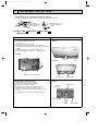
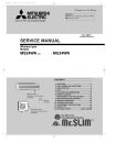
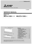
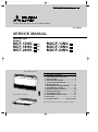
FLOOR AND CEILING TYPE AIR CONDITIONERS
No. OB270
SERVICE MANUAL
Wireless type
Models
MCF-13NVMCF-18NVMCF-24NV-
E4
(WH)
E3
(WH)
E3
(WH)
·MUCF-13NV·MUCF-18NV·MUCF-24NV-
E4
E3
E3
(When installed on the floor)
CONTENTS
(When installed on the ceiling)
1. TECHNICAL CHANGES ····································2
2. PART NAMES AND FUNCTIONS······················2
3. SPECIFICATION·················································4
4. NOISE CRITERIA CURVES ·······························5
5. OUTLINES AND DIMENSIONS ·························7
6. WIRING DIAGRAM ············································9
7. REFRIGERANT SYSTEM DIAGRAM ··············12
8. PERFORMANCE CURVES ······························14
9. MICROPROCESSOR CONTROL ····················28
10. SERVICE FUNCTIONS·····································34
11. TROUBLESHOOTING ······································35
12. DISASSEMBLY INSTRUCTIONS·····················41
13. PARTS LIST······················································47
14. OPTIONAL PARTS ······················BACK COVER
W As for parts lists, all sub number’s series are included.
OB270--1.qxp
1
4/13/01 2:59 PM
Page 2
TECHNICAL CHANGES
MCF-13NV- E3 · MUCF-13NV- E3
MCF-13NV- E4 · MUCF-13NV- E4
1. Remote controller has changed.
SWING button is removed, but SWING MODE function is available by VANE CONTROL button.
MCF-18NV- E2 · MUCF-18NV- E2
MCF-18NV- E3 · MUCF-18NV- E3
1. Remote controller has changed.
SWING button is removed, but SWING MODE function is available by VANE CONTROL button.
MCF-24NV- E2 · MUCF-24NV- E2
MCF-24NV- E3 · MUCF-24NV- E3
1. Remote controller has changed.
SWING button is removed, but SWING MODE function is available by VANE CONTROL button.
2
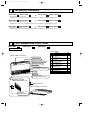
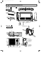
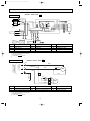
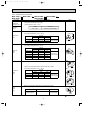
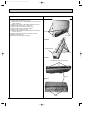
PART NAMES AND FUNCTIONS
MCF-13NV -
E4
MCF-18NV -
E3
MCF-24NV -
E3
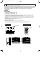
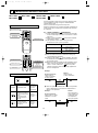
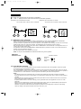
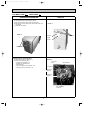
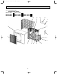
INDOOR UNIT
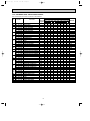
ACCESSORIES
Item
(When installed on the floor)
Vertical vanes
Horizontal vane
Operation indicator lamp
Receiving section
Front panel
Air cleaning filter
(white bellows type)(option)
Air inlet
Air filter
Deodorizing filter
(gray sponge type)(option)
Operation section
(When the air inlet grille is opened.)
Remote controller
(When installed on the ceiling)
Emergency
operation switch
2
Installation plate
Unit fixing screw
5 o 12mm
Wireless remote
controller
Remote controller
mounting hardware
Fixing screw for
3.5 o 16mm (Black)
Battery (AAA) for
remote controller
Drain hose
Drain pipe cover
Knockout cover
Screw for
4 o 10mm
Q'ty
2
2
1
1
2
2
1
1
1
2
OB270--1.qxp
4/13/01 2:59 PM
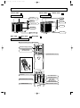
MUCF-13NV -
Page 3
MUCF-18NV -
E4
E3
MUCF-24NV -
E3
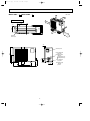
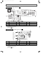
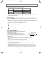
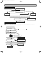
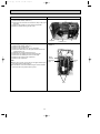
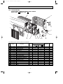
OUTDOOR UNIT
OUTDOOR UNIT
Air inlet
(back and side)
Air inlet
Piping
Piping
Drain hose
Drain hose
Air outlet
Air outlet
Drain outlet
Drain outlet
MCF-13NV -
E4
MCF-18NV -
E3
MCF-24NV -
E3
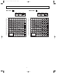
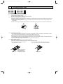
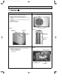
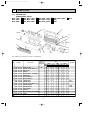
REMOTE CONTROLLER
Signal transmitting section
Operation display section
OPERATE /STOP
(ON /OFF)button
PM
AM
TOO
ON/OFF WARM
TOO
COOL
TEMPERATURE buttons
Open the front lid.
Open the front lid.
CLOCK
PM
WARM
COOL
AM
FAN SPEED CONTROL button
TOO
ON/OFF WARM
FAN
TOO
COOL
STOP
OFF-TIMER button
I FEEL COOL
FAN
FAN SPEED CONTROL button
OPERATION SELECT button
VANE
START
FAN
STOP
HR.
VANE
START
MIN.
RESET CLOCK
HR.
DRY
MODE
I FEEL COOL
FAN
DRY
MODE
OPERATION SELECT button
RESET button
MIN.
RESET CLOCK
RESET button
ON-TIMER button
HR. button
OFF-TIMER
button
MIN. button
ON-TIMER
button
(TIME
SET button)
HR.
button
CLOCK SET button
MIN. button
VANE
CONTROL
button
(TIME
SET button)
CLOCK SET button
VANE CONTROL button
3
OB270--1.qxp
3
4/13/01 2:59 PM
Page 4
SPECIFICATION
Indoor model
Function
MCF-13NV - E4
Cooling
Single phase
220-240V, 50Hz
3.7
1.6
678
10
6.3-6.3
1,310-1,380
Power supply
Fan
motor
Electrical
data
Capacity
Capacity
kW
Dehumidification
R/h
Air flow(High)
K /h
Power outlet
A
Running current
A
Power input
W
Auxiliary heater
A(kW)
Power factor
%
Starting current
A
Fan motor current
A
Coefficient of performance(C.O.P)
Model
Winding
"
resistance(at20:)
95-91
35-38
0.56-0.58
2.82-2.68
RB4V19-AB
WHT-BLK 203.2 BLK-YLW 45.9
YLW-BLU 32.7 BLU-BRN 44.4
BRN-RED 23.3
Special
remarks
Fan
motor
Compressor
Electrical
data
Special
remarks
Dimensions WOHOD
mm
Weight
kg
Air direction
Sound level (High)
dB
Fan speed (High)
rpm
Fan speed regulator
Thermistor RT11(at25:)
k"
Thermistor RT12(at25:)
k"
Outdoor model
Capacity Air flow (High)
K /h
Compressor motor current
A
Fan motor current
A
Model
Output
W
Winding
"
resistance(at20:)
Model
Winding
"
resistance(at20:)
Dimensions WOHOD
mm
Weight
kg
Sound level (High)
dB
Fan speed (High)
rpm
Fan speed regulator
Refrigerant filling
kg
capacity(R22)
Refrigerating oil (Model)
cc
43-44
1,080-1,130
MUCF-13NV - E4
1,848-1,980
5.74-5.72
0.30
RH-231VHAT
1,100
C-R 2.11
C-S 3.97
RA6V33-CB
WHT-BLK 176
BLK-RED 413
780o540o255
34
49
700-750
1
MCF-18NV - E3
Cooling
Single phase
240V, 50Hz
5.0
2.4
780
15
8.9-8.8
1,920-2,010
MCF-24NV - E3
Cooling
Single phase
240V, 50Hz
6.4
3.4
840
25
13.3-12.9
2,870-2,970
98-95
98-96
51-55
59-59
0.69-0.69
0.91-0.91
2.60-2.49
2.23-2.15
RB4V25-AB
RB4V36-AB
WHT-BLK 182.2 BLK-YLW 68.9 WHT-BLK 82.9 BLK-YLW 65.6
YLW-BLU 47.5 BLU-BRN 31.5
YLW-BLU 36.0 BLU-BRN 27.0
BRN-RED 22.9
BRN-RED 13.7
1,100O650O180
26
5
46-47
48-48
1,220-1,260
1,310-1,330
3
10
10
MUCF-18NV - E3
MUCF-24NV - E3
2,190-2,286
2,286-2,358
8.21-8.11
12.39-11.99
0.39
0.55
NH-33VMDT
NH-47VMDT
1,500
2,200
C-R 1.20
C-R 0.96
C-S 2.70
C-S 2.07
RA6V50-OG
RA6V60-AC
WHT-BLK 116
WHT-BLK 81 BLK-YLW 92
BLK-RED 111
BLK-RED 102
850o605o290
55
61
52
53
810-845
860-886
1
2
0.85
1.50
2.15
520 (MS56)
1,200 (MS32N1)
1200 (MS32N1)
NOTE:Test conditions are based on ISO 5151
Cooling : Indoor DB27°C WB19°C
Outdoor DB35°C WB(24°C)
4
OB270--1.qxp
4/13/01 2:59 PM
4
Page 5
NOISE CRITERIA CURVES
NOISE CRITERIA CURVES
MCF-13NV -
MUCF-13NV -
E4
SPEED
SPL(dB(A))
High
43-44
LINE
Test conditions,
Cooling : DB 27:
OCTAVE BAND SOUND PRESSURE LEVEL, dB re 0.002 MICRO BAR
OCTAVE BAND SOUND PRESSURE LEVEL, dB re 0.002 MICRO BAR
NC-70
60
NC-60
50
NC-50
40
NC-40
30
NC-30
APPROXIMATE
THRESHOLD OF
HEARING FOR
CONTINUOUS
NOISE
63
NC-20
125
MCF-18NV -
250
500
1000
2000
4000
WB (24:)
70
NC-70
60
NC-60
50
NC-50
40
NC-40
30
NC-30
20
10
8000
APPROXIMATE
THRESHOLD OF
HEARING FOR
CONTINUOUS
NOISE
63
NC-20
125
250
MUCF-18NV -
E3
SPEED
SPL(dB(A))
High (240V)
47
High (220V)
46
500
1000
2000
4000
8000
BAND CENTER FREQUENCIES, Hz
E3
LINE
Test conditions,
Cooling : DB 27:
SPEED
SPL(dB(A))
High
52
LINE
Test conditions,
Cooling : DB 35:
WB 19:\
WB (24:
90
OCTAVE BAND SOUND PRESSURE LEVEL, dB re 0.002 MICRO BAR
90
OCTAVE BAND SOUND PRESSURE LEVEL, dB re 0.002 MICRO BAR
48
80
BAND CENTER FREQUENCIES, Hz
80
70
NC-70
60
NC-60
50
NC-50
40
NC-40
30
NC-30
10
High
LINE
90
70
20
SPL(dB(A))
Test conditions,
Cooling : DB 35:
80
10
SPEED
WB 19:\
90
20
E4
APPROXIMATE
THRESHOLD OF
HEARING FOR
CONTINUOUS
NOISE
63
125
NC-20
250
500
1000
2000
4000
8000
80
70
NC-70
60
NC-60
50
NC-50
40
NC-40
30
NC-30
20
10
APPROXIMATE
THRESHOLD OF
HEARING FOR
CONTINUOUS
NOISE
63
125
NC-20
250
500
1000
2000
4000
BAND CENTER FREQUENCIES, Hz
BAND CENTER FREQUENCIES, Hz
5
8000
OB270--1.qxp
4/13/01 2:59 PM
MCF-24NV -
Page 6
MUCF-24NV -
E3
SPEED
SPL(dB(A))
High
48
LINE
Test conditions,
Cooling : DB 27:
OCTAVE BAND SOUND PRESSURE LEVEL, dB re 0.002 MICRO BAR
OCTAVE BAND SOUND PRESSURE LEVEL, dB re 0.002 MICRO BAR
SPL(dB(A))
High
53
LINE
WB (24:)
90
80
70
NC-70
60
NC-60
50
NC-50
40
NC-40
30
NC-30
10
SPEED
Test conditions,
Cooling : DB 35:
WB 19:\
90
20
E3
APPROXIMATE
THRESHOLD OF
HEARING FOR
CONTINUOUS
NOISE
63
125
NC-20
250
500
1000
2000
4000
8000
BAND CENTER FREQUENCIES, Hz
80
70
NC-70
60
NC-60
50
NC-50
40
NC-40
30
NC-30
20
10
APPROXIMATE
THRESHOLD OF
HEARING FOR
CONTINUOUS
NOISE
63
125
NC-20
250
500
1000
2000
4000
BAND CENTER FREQUENCIES, Hz
6
8000
OB270--1.qxp
4/13/01 2:59 PM
5
Page 7
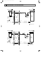
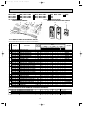
OUTLINES AND DIMENSIONS
MCF-18NV -
E4
Unit: mm
E3
E3
114
MCF-13NV MCF-24NV -
INDOOR UNIT
80.8
16
906
112.8
(When installed on the floor)
50c
616.5
50cm or more
650
50cm or more
93
77
m o (When installed on the ceiling)
rm
143
113
50cm or more
42.5
100cm or more
170
ore
180
1100
58
19
162
Liquid line
[6.35 (MCF-13/18)
[9.52 (MCF-24)
Gas line
[12.7 (MCF-13)
[15.88 (MCF-18/24)
Wireless remote controller
E4
100mm or more
MUCF-13NV -
REQUIRED SPACE
OUTDOOR UNIT
100
mm
ore
rm
mo
m
100
or m
ore
320
255
285
320
121
109
15
ore
rm
mo
m
400
35
0m
m
or
mo
re
25
Service panel
10
155
90
260
43- 53
540
Liquid refrigerant
pipe joint
Refrigerant pipe
(flared) [6.35
40
122
500
780
104
74
7
Gas refrigerant
pipe joint
Refrigerant pipe
(flared) [12.7
4/13/01 2:59 PM
MUCF-18NV -
E3
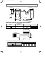
Page 8
MUCF-24NV -
Unit: mm
E3
100mm or more
OB270--1.qxp
OUTDOOR UNIT
100
mm
or m
or m
ore
20
290
310
345
248
35
350
ore
mm
100
ore
rm
mo
m
500
35
0m
or
mo
re
Drainage
3holes [33
30
605
Service panel
30
157
100
292
20
m
50
133
500
850
35
161
74
8
Liquid refrigerant
pipe joint
Refrigerant pipe
(flared)
[6.35(MUCF-18)
[9.52(MUCF-24)
Gas refrigerant
pipe joint
Refrigerant pipe
(flared)
[15.88
OB270--1.qxp
4/13/01 2:59 PM
6
Page 9
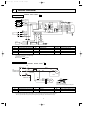
WIRING DIAGRAM
MODEL MCF-13NV-
INDOOR UNIT
E4
TB
CIRCUIT BREAKER
PE GRN/YLW
N
BLU
CN
112
HIC1
L
BRN
3
2
~/N 220-240V
1
50Hz
3
NR11
POWER SUPPLY
4
52C
SR143
N
220-240V~
2
RT12
WHT
LDC11
ORN 2
RED 3
BLK
LDFH
LDFM
LDFL
1
4
YLW 5
BLU 6
7
CN
104
CN
101
BLU
MF
8
ELECTRONIC CONTROL P.C BOARD
GRN/YLW
5
6
MV
5
DISP/
RECEIVER
P.C.BOARD
WHT
ORN
RED
BLK
YLW
BLU
BRN
6
5
WHT
CN
151
CN
113
4
REMOTE
CONTROLLER
SR142
F11
2
LDCOM
LDC12
SR144
TRANS
CN201
GRN/YLW
TO OUTDOOR
UNIT
CONNECTING
C11
2
SW/THERMO
P.C.BOARD
AUTO RESTART
RT11
ASSY
SYMBOL
NAME
SYMBOL
C11
INDOOR FAN MOTOR CAPACITOR
MV
F11
FUSE (3.15A)
NR11
VARISTOR
TB
TERMINAL BLOCK
HIC1
DC/DC CONVERTER
RT11
ROOM TEMPERATURE THERMISTOR
52C
COMPRESSOR CONTACTOR
FAN MOTOR(INNER PROTECTOR)
RT12
INDOOR COIL THERMISTOR
MF
NAME
SYMBOL
NAME
SR142~SR144 SOLID STATE RELAY
VANE MOTOR
VG79B036H01
NOTE:1. About the outdoor side electric wiring, refer to the outdoor unit electric wiring diagram for servicing.
2. Use copper conductors only.(For field wiring)
3. Symbols below indicate;
: Terminal block,
: Connector
OUTDOOR UNIT
MODEL MUCF-13NV-
E3
TB
TO
INDOOR UNIT
CONNECTING
220-240V~ 2
W
N
W
WHT
WHT
C
WHT
F
C1
BLU
RED
S
MC
R
BLK
GRN/YLW
C2
WHT
BLU
RED
WHT
1
BLK
2
RED
3
MF
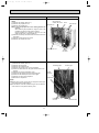
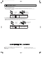
1Slide the sleeve.
2Pull the wire while pushing the locking lever.
SYMBOL
NAME
SYMBOL
C1
COMPRESSOR CAPACITOR
F
C2
OUTDOOR FAN MOTOR CAPACITOR
MC
NAME
FUSE 2A
COMPRESSOR (INNER PROTECTOR)
SYMBOL
NAME
OUTDOOR FAN MOTOR (INNER PROTECTOR)
MF
TB
NOTE:1. Use copper conductors only (For field wiring).
2. “W” shows the terminals with a lock mechanism, so they cannnot be removed when you pull the lead wire.
Be sure yo pull the lead wire by pushing the locking lever (projected part) of the terminal with a finger.
9
TERMINAL BLOCK
SG79B458H01
OB270--1.qxp
4/13/01 2:59 PM
Page 10
MODEL MCF-18NV-
INDOOR UNIT
E3
TB
CIRCUIT BREAKER
PE GRN/YLW
N
BLU
L
BRN
3
2
~/N 220-240V
1
50Hz
4
3
52C
RT12
WHT
LDC11
ORN 2
RED 3
BLK
LDFH
1
4
YLW 5
BLU 6
LDFM
LDFL
7
CN
104
CN
101
5
WHT
CN
151
CN
113
MF
8
ELECTRONIC CONTROL P.C BOARD
GRN/YLW
6
5
DISP/
RECEIVER
P.C.BOARD
WHT
ORN
RED
BLK
YLW
BLU
BRN
5
6
4
REMOTE
CONTROLLER
SR142
F11
BLU
2
SR144
2
LDCOM
LDC12
SR143
GRN/YLW
220-240V~
C11
TRANS
CN201
N
NR11
POWER SUPPLY
TO OUTDOOR
UNIT
CONNECTING
2
CN
112
HIC1
AUTO RESTART
MV
SW/THERMO
P.C.BOARD
RT11
ASSY
SYMBOL
NAME
SYMBOL
C11
INDOOR FAN MOTOR CAPACITOR
MV
F11
FUSE (3.15A)
NR11
VARISTOR
TB
TERMINAL BLOCK
HIC1
DC/DC CONVERTER
RT11
ROOM TEMPERATURE THERMISTOR
52C
COMPRESSOR CONTACTOR
FAN MOTOR (INNER PROTECTOR)
RT12
INDOOR COIL THERMISTOR
MF
NAME
SYMBOL
NAME
SR142~SR144 SOLID STATE RELAY
VANE MOTOR
VG79B032H01
NOTE:1. About the outdoor side electric wiring, refer to the outdoor unit electric wiring diagram for servicing.
2. Use copper conductors only.(For field wiring)
3. Symbols below indicate;
: Terminal block,
: Connector
MODEL MUCF-18NV-
OUTDOOR UNIT
E3
2
220-240V~
TO INDOOR UNIT
CONNECTING
TB
WHT
C
WHT
N
C1
BLU
RED
MC
S
BLK
GRN/YLW
F
C2
RED
ORN
WHT
BLU
SYMBOL
NAME
SYMBOL
C1
COMPRESSOR CAPACITOR
F
C2
OUTDOOR FAN MOTOR CAPACITOR
MC
R
1
2
3
4
RED
ORN
MF
WHT
BLK
SYMBOL
NAME
FUSE 2A
NAME
MF
OUTDOOR FAN MOTOR (INNER PROTECTOR)
COMPRESSOR (INNER PROTECTOR)
TB
TERMINAL BLOCK
NOTE:1. About the outdoor side electric wiring, refer to the outdoor unit electric wiring diagram for servicing.
2. Use copper conductors only.(For field wiring)
3. Symbols below indicate;
: Terminal block,
: Connector
10
SG79J002H01
OB270--1.qxp
4/13/01 2:59 PM
Page 11
MODEL MCF-24NV-
INDOOR UNIT
E3
TB
CIRCUIT BREAKER
PE GRN/YLW
N
BLU
CN
112
HIC1
L
BRN
3
2
~/N 220-240V
1
50Hz
3
52C
3
BLU
CN
101
CN
113
CN
104
CN
151
WHT
LDCOM
WHT
LDC11
ORN 2
RED 3
BLK
LDC12
LDFH
1
4
YLW 5
BLU 6
LDFM
LDFL
5
WHT
ORN
RED
BLK
YLW
BLU
BRN
8
ELECTRONIC CONTROL P.C BOARD
GRN/YLW
6
4
MV
SW/THERMO
P.C.BOARD
AUTO RESTART
ASSY
RT11
SYMBOL
NAME
C11
INDOOR FAN MOTOR CAPACITOR
F11
FUSE (3.15A)
NR11
VARISTOR
TB
TERMINAL BLOCK
HIC1
DC/DC CONVERTER
RT11
ROOM TEMPERATURE THERMISTOR
52C
CONTACTOR
FAN MOTOR (INNER PROTECTOR)
RT12
INDOOR COIL THERMISTOR
MF
SYMBOL
MV
NAME
SYMBOL
NAME
SR142~SR144 SOLID STATE RELAY
VANE MOTOR
NOTE:1. About the outdoor side electric wiring, refer to the outdoor unit electric wiring diagram for servicing.
2. Use copper conductors only.(For field wiring)
3. Symbols below indicate;
: Terminal block,
: Connector
MODEL MUCF-24NV-
OUTDOOR UNIT
MF
5
RED
DISP/
RECEIVER
P.C.BOARD
RT12
6
5
REMOTE
CONTROLLER
SR142
F11
2
7
N
220-240V~
SR144
SR143
GRN/YLW
2
C11
TRANS
CN201
TO OUTDOOR
UNIT
220-240V~
CONNECTING
NR11
POWER SUPPLY
4
2
VG79B033H01
E3
C2
TB2
RED 1
X1 3
GRY 5
6
A1/a WHT
RED
52C
A2/b
52C
2
WHT 2
1
BLU
N
C1
RED 7
X1
BLU 26F1
WHT
1
654321
MF
RED S
MC
BLK
8
BLU
CR
YLW
BLK
WHT
ORN
RED
RED
YLW
BLK
WHT
ORN
RED
F
RED
BLU
TO INDOOR UNIT CONNECTING
TB
3
C
R
GRN/YLW
SYMBOL
NAME
SYMBOL
NAME
SYMBOL
C1
COMPRESSOR CAPACITOR
MC
COMPRESSOR (INNER PROTECTOR)
X1
FAN MOTOR RELAY
C2
OUTDOOR FAN MOTOR CAPACITOR
MF
OUTDOOR FAN MOTOR (INNER PROTECTOR)
26F1
THERMOSTAT (AIRFLOW CONTROL)
CR
F
SURGE ABSORBER
FUSE 2A
TB
TB2
TERMINAL BLOCK
TERMINAL BLOCK
52C
COMPRESSOR CONTACTOR
NOTE:1. About the outdoor side electric wiring, refer to the outdoor unit electric wiring diagram for servicing.
2. Use copper conductors only.(For field wiring)
3. Symbols below indicate;
: Terminal block,
: Connector
11
NAME
SG79J078H01
OB270--1.qxp
7
4/13/01 2:59 PM
Page 12
REFRIGERANT SYSTEM DIAGRAM
Unit:mm
MCF-13NV
MUCF-13NV
E4
INDOOR UNIT
Refrigerant pipe
[12.7
(With heat insulation)
Indoor
heat
exchanger
Indoor coil
thermistor
RT12
OUTDOOR UNIT
Stop valve
(with service port)
Distributor
Flared
connection
Stop valve
[3.0✕[1.6✕ 300
Refrigerant flow
MUCF-18NV
E3
Refrigerant pipe
{15.88
(With heat insulation)
Indoor
heat
exchanger
Indoor coil
thermistor
RT12
Strainer
Capillary tube
Refrigerant pipe
[6.35
(With heat insulation)
INDOOR UNIT
Distributor
Outdoor
heat
exchanger
Compressor
Room
temperature
thermistor
RT11
MCF-18NV
E4
OUTDOOR UNIT
Accumulator
Stop valve
(with service port)
Flared
connection
Room
temperature
thermistor
RT11
E3
Outdoor
heat
exchanger
Compressor
Stop valve
Capillary tube
Strainer
{3.0✕{2.0✕ 700
Refrigerant pipe
{6.35
(With heat insulation)
Refrigerant flow
12
OB270--1.qxp
4/13/01 2:59 PM
Page 13
MCF-24NV
MUCF-24NV
E3
INDOOR UNIT
Refrigerant pipe
{15.88
(With heat insulation)
Indoor
heat
exchanger
Indoor coil
thermistor
RT12
Distributor
Unit:mm
E3
OUTDOOR UNIT
Accumulator
Stop valve
(with service port)
Flared
connection
Outdoor
heat
exchanger
Compressor
Room
temperature
thermistor
RT11
Capillary tube
{3.0✕{2.0✕ 700
Stop valve
Refrigerant pipe
{9.52
(With heat insulation)
Strainer
Capillary tube
Discharge
{3.0✕{1.6✕ 350 pressure
regulator
Refrigerant flow
REFRIGERANT PIPING MAX. LENGTH & MAX. HEIGHT DIFFERENCE
Refrigerant piping
Max. length : m
A
Models
MCF-13NV MCF-18NV MCF-24NV -
Piping size O.D. : mm
E4
15
E3
E3
Gas
Liquid
{12.7
{6.35
{15.88
{9.52
Indoor unit
Max. Height
difference *
5m
Outdoor unit
*Height difference should be within
5m regardless of which unit,
indoor or outdoor position is high.
A: Refrigerant piping
Max. length
15m
ADDITIONAL REFRIGERANT CHARGE (R22 : g)
If pipe length exceeds 7m, additional refrigerant (R22) charge is required.
Models
MCF-13NV MCF-18NV MCF-24NV -
E4
E3
E3
Outdoor unit
precharged
Refrigerant piping length (one way)
7m
8m
9m
0
15
30
850
1,500
2,150
Calculation : ✕g=15g/m✕(Refrigerant piping length (m)-7)
13
10m 11m 12m 13m 14m 15m
45
60
75
90
105
120
OB270--1.qxp
8
4/13/01 2:59 PM
Page 14
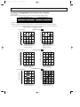
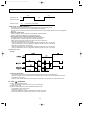
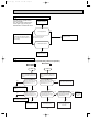
PERFORMANCE CURVES
The standard data contained in these specifications apply only to the operation of the air conditioner under normal condition.
Operating conditions vary according to the areas where these units are installed. The following information has been provided
to clarify the operating characteristics of the air conditioner under the conditions indicated by the performance curve.
(1) GUARANTEED VOLTAGE
198~264V, 50Hz
(2) AIR FLOW
Air flow should be set at MAX.
(3) MAIN READINGS
(1) Indoor intake air wet-bulb temperature : ˚C WB
(2) Indoor outlet air wet-bulb temperature : ˚C WB
(3) Outdoor intake air dry-bulb temperature : ˚C DB
(4) Total input : W
The table of Indoor air wet-bulb temperature difference at the bottom left on page 15 shows the difference between the
indoor intake air wet-bulb temperature and the indoor outlet air wet-bulb temperature for your reference at service.
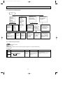
How to measure the indoor air wet-bulb temperature difference
1. Attach at least 2. sets of wet-and-dry-bulb thermometers to the indoor air intake as shown in the figure, and at least 2 sets
of wet-and-dry-bulb thermometers to the indoor air outlet. The thermometers must be attached to the position where air
speed is high.
2. Attach at least 2 sets of dry-bulb thermometers to the outdoor air intake.
Cover the thermometers to avoid direct rays of the sun.
3. Check that the air filter is cleaned.
4. Open windows and doors of the room.
5. Press the EMERGENCY OPERATION switch to start the EMERGENCY operation.
6. When system stabilizes after more than 15 minutes, measure temperature and take an average temperature.
7. 10 minutes later, measure temperature again and check that the temperature does not change.
INDOOR UNIT
OUTDOOR UNIT
Wet-and dry-bulb
thermometers
Air out
Dry-bulb
thermometers
Air in
FRONT VIEW
9.5
11.9
14.2
8.7
10.8
12.8
7.8
9.7
11.5
7.0
8.7
10.3
6.2
7.7
9.0
MCF-24NV- E3
15.7
MCF-18NV- E3
13.1
MCF-13NV- E4
10.4
SIDE VIEW
14
OB270--1.qxp
4/13/01 2:59 PM
Page 15
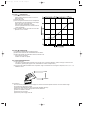
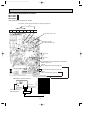
OUTDOOR LOW PRESSURE AND OUTDOOR UNIT CURRENT
COOL operation
1 Both indoor and outdoor units are under the same temperature/humidity condition.
Dry Bulb temperature (˚C)
20
25
30
Relative humidity (%)
50
60
70
2 Air flow should be set at MAX..
3 The unit of pressure has been changed to MPa on the international system of units(SI unit system).
The converted score against the traditional unit system can be gotten according to the formula below.
f • [Gauge])
1(MPa [Gauge]) =10.2(kgf/f
MUCF-13NV-
8
0.7
220-240V
6
0.6
5
0.5
4
0.4
3
0.3
8
0.8
7
0.7
6
0.6
5
0.5
4
0.4
3
0.3
7
220-240V
6
5
4
3
25
30 32 (:)
18 20
(%)
50
60
70
Ambient temperature (:)
Ambient humidity(%)
MUCF-18NV-
(kgf/F•G)(MPa•G)
Outdoor low pressure
Outdoor unit current (A)
7
E4
10
220-240V
220V
9
7
6
18 20
50
25
60
5
30 32 ( C)
(%)
70
0.6
0.5
4
0.4
3
2
25
60
30 32 ( C)
(%)
70
E3
14
Outdoor unit current (A)
Outdoor low pressure
0.7
5
18 20
50
Ambient temperature (°C)
Ambient humidity(%)
MUCF-24NV-
(kgf/F•G)(MPa•G)
6
240V
8
Ambient temperature (°C)
Ambient humidity(%)
7
18 20
25
30 32 (:)
50
60
70
(%)
Ambient temperature (:)
Ambient humidity(%)
E3
Outdoor unit current (A)
Outdoor low pressure
(kgf/F•G)(MPa•G)
0.8
8
220-240V
220V
13
240V
12
11
10
9
0.3
8
0.2
18 20
50
25
60
7
30 32 ( C)
(%)
70
Ambient temperature (°C)
Ambient humidity(%)
18 20
50
25
60
30 32 ( C)
(%)
70
Ambient temperature (°C)
Ambient humidity(%)
15
OB270--1.qxp
4/13/01 2:59 PM
Page 16
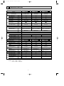
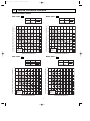
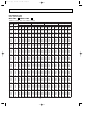
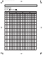
PERFORMANCE DATA
COOL operation(220V)
MCF-13NV -
E4
:MUCF-13NV -
E4
CAPACITY : 3.7(kW) SHF : 0.70 INPUT : 1310(W)
OUTDOOR DB(;)
INDOOR INDOOR
DB(;) WB(;)
21
18
21
20
22
18
22
20
22
22
23
18
23
20
23
22
24
18
24
20
24
22
24
24
25
18
25
20
25
22
25
24
26
18
26
20
26
22
26
24
26
26
27
18
27
20
27
22
27
24
27
26
28
18
28
20
28
22
28
24
28
26
29
18
29
20
29
22
29
24
29
26
30
18
30
20
30
22
30
24
30
26
31
18
31
20
31
22
31
24
31
26
32
18
32
20
32
22
32
24
32
26
Q
4.35
4.53
4.35
4.53
4.72
4.35
4.53
4.72
4.35
4.53
4.72
4.96
4.35
4.53
4.72
4.96
4.35
4.53
4.72
4.96
5.11
4.35
4.53
4.72
4.96
5.11
4.35
4.53
4.72
4.96
5.11
4.35
4.53
4.72
4.96
5.11
4.35
4.53
4.72
4.96
5.11
4.35
4.53
4.72
4.96
5.11
4.35
4.53
4.72
4.96
5.11
SHC
2.26
1.81
2.43
1.99
1.51
2.61
2.18
1.70
2.78
2.36
1.89
1.39
2.96
2.54
2.08
1.59
3.13
2.72
2.26
1.78
1.23
3.30
2.90
2.45
1.98
1.43
3.48
3.08
2.64
2.18
1.63
3.65
3.26
2.83
2.38
1.84
3.83
3.44
3.02
2.58
2.04
4.00
3.63
3.21
2.78
2.25
4.17
3.81
3.40
2.97
2.45
21
25
27
30
SHF INPUT Q SHC SHF INPUT Q SHC SHF INPUT Q SHC SHF INPUT
0.52 1048 4.16 2.16 0.52 1100 4.00 2.08 0.52 1153 3.85 2.00 0.52 1205
0.40 1100 4.35 1.74 0.40 1166 4.22 1.69 0.40 1192 4.07 1.63 0.40 1245
0.56 1048 4.16 2.33 0.56 1100 4.00 2.24 0.56 1153 3.85 2.15 0.56 1205
0.44 1100 4.35 1.91 0.44 1166 4.22 1.86 0.44 1192 4.07 1.79 0.44 1245
0.32 1140 4.55 1.46 0.32 1212 4.44 1.42 0.32 1245 4.26 1.36 0.32 1297
0.60 1048 4.16 2.50 0.60 1100 4.00 2.40 0.60 1153 3.85 2.31 0.60 1205
0.48 1100 4.35 2.09 0.48 1166 4.22 2.02 0.48 1192 4.07 1.95 0.48 1245
0.36 1140 4.55 1.64 0.36 1212 4.44 1.60 0.36 1245 4.26 1.53 0.36 1297
0.64 1048 4.16 2.66 0.64 1100 4.00 2.56 0.64 1153 3.85 2.46 0.64 1205
0.52 1100 4.35 2.26 0.52 1166 4.22 2.19 0.52 1192 4.07 2.12 0.52 1245
0.40 1140 4.55 1.82 0.40 1212 4.44 1.78 0.40 1245 4.26 1.70 0.40 1297
0.28 1192 4.77 1.34 0.28 1258 4.66 1.31 0.28 1297 4.51 1.26 0.28 1362
0.68 1048 4.16 2.83 0.68 1100 4.00 2.72 0.68 1153 3.85 2.62 0.68 1205
0.56 1100 4.35 2.43 0.56 1166 4.22 2.36 0.56 1192 4.07 2.28 0.56 1245
0.44 1140 4.55 2.00 0.44 1212 4.44 1.95 0.44 1245 4.26 1.87 0.44 1297
0.32 1192 4.77 1.53 0.32 1258 4.66 1.49 0.32 1297 4.51 1.44 0.32 1362
0.72 1048 4.16 3.00 0.72 1100 4.00 2.88 0.72 1153 3.85 2.77 0.72 1205
0.60 1100 4.35 2.61 0.60 1166 4.22 2.53 0.60 1192 4.07 2.44 0.60 1245
0.48 1140 4.55 2.18 0.48 1212 4.44 2.13 0.48 1245 4.26 2.04 0.48 1297
0.36 1192 4.77 1.72 0.36 1258 4.66 1.68 0.36 1297 4.51 1.63 0.36 1362
0.24 1258 4.96 1.19 0.24 1323 4.88 1.17 0.24 1362 4.74 1.14 0.24 1402
0.76 1048 4.16 3.16 0.76 1100 4.00 3.04 0.76 1153 3.85 2.92 0.76 1205
0.64 1100 4.35 2.78 0.64 1166 4.22 2.70 0.64 1192 4.07 2.60 0.64 1245
0.52 1140 4.55 2.37 0.52 1212 4.44 2.31 0.52 1245 4.26 2.21 0.52 1297
0.40 1192 4.77 1.91 0.40 1258 4.66 1.86 0.40 1297 4.51 1.81 0.40 1362
0.28 1258 4.96 1.39 0.28 1323 4.88 1.37 0.28 1362 4.74 1.33 0.28 1402
0.80 1048 4.16 3.33 0.80 1100 4.00 3.20 0.80 1153 3.85 3.08 0.80 1205
0.68 1100 4.35 2.96 0.68 1166 4.22 2.87 0.68 1192 4.07 2.77 0.68 1245
0.56 1140 4.55 2.55 0.56 1212 4.44 2.49 0.56 1245 4.26 2.38 0.56 1297
0.44 1192 4.77 2.10 0.44 1258 4.66 2.05 0.44 1297 4.51 1.99 0.44 1362
0.32 1258 4.96 1.59 0.32 1323 4.88 1.56 0.32 1362 4.74 1.52 0.32 1402
0.84 1048 4.16 3.50 0.84 1100 4.00 3.36 0.84 1153 3.85 3.23 0.84 1205
0.72 1100 4.35 3.13 0.72 1166 4.22 3.04 0.72 1192 4.07 2.93 0.72 1245
0.60 1140 4.55 2.73 0.60 1212 4.44 2.66 0.60 1245 4.26 2.55 0.60 1297
0.48 1192 4.77 2.29 0.48 1258 4.66 2.24 0.48 1297 4.51 2.17 0.48 1362
0.36 1258 4.96 1.78 0.36 1323 4.88 1.76 0.36 1362 4.74 1.70 0.36 1402
0.88 1048 4.16 3.66 0.88 1100 4.00 3.52 0.88 1153 3.85 3.39 0.88 1205
0.76 1100 4.35 3.30 0.76 1166 4.22 3.21 0.76 1192 4.07 3.09 0.76 1245
0.64 1140 4.55 2.91 0.64 1212 4.44 2.84 0.64 1245 4.26 2.72 0.64 1297
0.52 1192 4.77 2.48 0.52 1258 4.66 2.42 0.52 1297 4.51 2.35 0.52 1362
0.40 1258 4.96 1.98 0.40 1323 4.88 1.95 0.40 1362 4.74 1.89 0.40 1402
0.92 1048 4.16 3.83 0.92 1100 4.00 3.68 0.92 1153 3.85 3.54 0.92 1205
0.80 1100 4.35 3.48 0.80 1166 4.22 3.37 0.80 1192 4.07 3.26 0.80 1245
0.68 1140 4.55 3.09 0.68 1212 4.44 3.02 0.68 1245 4.26 2.89 0.68 1297
0.56 1192 4.77 2.67 0.56 1258 4.66 2.61 0.56 1297 4.51 2.53 0.56 1362
0.44 1258 4.96 2.18 0.44 1323 4.88 2.15 0.44 1362 4.74 2.08 0.44 1402
0.96 1048 4.16 4.00 0.96 1100 4.00 3.84 0.96 1153 3.85 3.69 0.96 1205
0.84 1100 4.35 3.65 0.84 1166 4.22 3.54 0.84 1192 4.07 3.42 0.84 1245
0.72 1140 4.55 3.28 0.72 1212 4.44 3.20 0.72 1245 4.26 3.06 0.72 1297
0.60 1192 4.77 2.86 0.60 1258 4.66 2.80 0.60 1297 4.51 2.71 0.60 1362
0.48 1258 4.96 2.38 0.48 1323 4.88 2.34 0.48 1362 4.74 2.27 0.48 1402
16
OB270--1.qxp
4/13/01 2:59 PM
Page 17
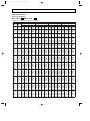
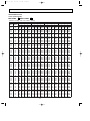
PERFORMANCE DATA
COOL operation(220V)
MCF-13NV -
E4
:MUCF-13NV -
E4
CAPACITY : 3.7(kW) SHF : 0.70 INPUT : 1310(W)
OUTDOOR DB(;)
INDOOR INDOOR
DB(;) WB(;)
21
18
21
20
22
18
22
20
22
22
23
18
23
20
23
22
24
18
24
20
24
22
24
24
25
18
25
20
25
22
25
24
26
18
26
20
26
22
26
24
26
26
27
18
27
20
27
22
27
24
27
26
28
18
28
20
28
22
28
24
28
26
29
18
29
20
29
22
29
24
29
26
30
18
30
20
30
22
30
24
30
26
31
18
31
20
31
22
31
24
31
26
32
18
32
20
32
22
32
24
32
26
Q
3.63
3.81
3.63
3.81
4.03
3.63
3.81
4.03
3.63
3.81
4.03
4.26
3.63
3.81
4.03
4.26
3.63
3.81
4.03
4.26
4.48
3.63
3.81
4.03
4.26
4.48
3.63
3.81
4.03
4.26
4.48
3.63
3.81
4.03
4.26
4.48
3.63
3.81
4.03
4.26
4.48
3.63
3.81
4.03
4.26
4.48
3.63
3.81
4.03
4.26
4.48
35
40
43
46
SHC SHF INPUT Q SHC SHF INPUT Q SHC SHF INPUT Q SHC SHF INPUT
1.89 0.52 1284 3.33 1.73 0.52 1362 3.20 1.66 0.52 1389 3.07 1.60 0.52 1415
1.52 0.40 1336 3.55 1.42 0.40 1402 3.42 1.37 0.40 1441 3.29 1.32 0.40 1480
2.03 0.56 1284 3.33 1.86 0.56 1362 3.20 1.79 0.56 1389 3.07 1.72 0.56 1415
1.68 0.44 1336 3.55 1.56 0.44 1402 3.42 1.51 0.44 1441 3.29 1.45 0.44 1480
1.29 0.32 1389 3.77 1.21 0.32 1467 3.64 1.17 0.32 1493 3.52 1.12 0.32 1520
2.18 0.60 1284 3.33 2.00 0.60 1362 3.20 1.92 0.60 1389 3.07 1.84 0.60 1415
1.83 0.48 1336 3.55 1.70 0.48 1402 3.42 1.64 0.48 1441 3.29 1.58 0.48 1480
1.45 0.36 1389 3.77 1.36 0.36 1467 3.64 1.31 0.36 1493 3.52 1.27 0.36 1520
2.32 0.64 1284 3.33 2.13 0.64 1362 3.20 2.05 0.64 1389 3.07 1.97 0.64 1415
1.98 0.52 1336 3.55 1.85 0.52 1402 3.42 1.78 0.52 1441 3.29 1.71 0.52 1480
1.61 0.40 1389 3.77 1.51 0.40 1467 3.64 1.46 0.40 1493 3.52 1.41 0.40 1520
1.19 0.28 1441 4.00 1.12 0.28 1507 3.89 1.09 0.28 1539 3.77 1.06 0.28 1572
2.47 0.68 1284 3.33 2.26 0.68 1362 3.20 2.18 0.68 1389 3.07 2.09 0.68 1415
2.13 0.56 1336 3.55 1.99 0.56 1402 3.42 1.92 0.56 1441 3.29 1.84 0.56 1480
1.77 0.44 1389 3.77 1.66 0.44 1467 3.64 1.60 0.44 1493 3.52 1.55 0.44 1520
1.36 0.32 1441 4.00 1.28 0.32 1507 3.89 1.24 0.32 1539 3.77 1.21 0.32 1572
2.61 0.72 1284 3.33 2.40 0.72 1362 3.20 2.30 0.72 1389 3.07 2.21 0.72 1415
2.29 0.60 1336 3.55 2.13 0.60 1402 3.42 2.05 0.60 1441 3.29 1.98 0.60 1480
1.94 0.48 1389 3.77 1.81 0.48 1467 3.64 1.75 0.48 1493 3.52 1.69 0.48 1520
1.53 0.36 1441 4.00 1.44 0.36 1507 3.89 1.40 0.36 1539 3.77 1.36 0.36 1572
1.07 0.24 1493 4.22 1.01 0.24 1559 4.09 0.98 0.24 1592 3.96 0.95 0.24 1624
2.76 0.76 1284 3.33 2.53 0.76 1362 3.20 2.43 0.76 1389 3.07 2.33 0.76 1415
2.44 0.64 1336 3.55 2.27 0.64 1402 3.42 2.19 0.64 1441 3.29 2.11 0.64 1480
2.10 0.52 1389 3.77 1.96 0.52 1467 3.64 1.90 0.52 1493 3.52 1.83 0.52 1520
1.70 0.40 1441 4.00 1.60 0.40 1507 3.89 1.55 0.40 1539 3.77 1.51 0.40 1572
1.25 0.28 1493 4.22 1.18 0.28 1559 4.09 1.14 0.28 1592 3.96 1.11 0.28 1624
2.90 0.80 1284 3.33 2.66 0.80 1362 3.20 2.56 0.80 1389 3.07 2.46 0.80 1415
2.59 0.68 1336 3.55 2.42 0.68 1402 3.42 2.33 0.68 1441 3.29 2.24 0.68 1480
2.26 0.56 1389 3.77 2.11 0.56 1467 3.64 2.04 0.56 1493 3.52 1.97 0.56 1520
1.87 0.44 1441 4.00 1.76 0.44 1507 3.89 1.71 0.44 1539 3.77 1.66 0.44 1572
1.43 0.32 1493 4.22 1.35 0.32 1559 4.09 1.31 0.32 1592 3.96 1.27 0.32 1624
3.05 0.84 1284 3.33 2.80 0.84 1362 3.20 2.69 0.84 1389 3.07 2.58 0.84 1415
2.74 0.72 1336 3.55 2.56 0.72 1402 3.42 2.46 0.72 1441 3.29 2.37 0.72 1480
2.42 0.60 1389 3.77 2.26 0.60 1467 3.64 2.19 0.60 1493 3.52 2.11 0.60 1520
2.04 0.48 1441 4.00 1.92 0.48 1507 3.89 1.86 0.48 1539 3.77 1.81 0.48 1572
1.61 0.36 1493 4.22 1.52 0.36 1559 4.09 1.47 0.36 1592 3.96 1.43 0.36 1624
3.19 0.88 1284 3.33 2.93 0.88 1362 3.20 2.82 0.88 1389 3.07 2.70 0.88 1415
2.90 0.76 1336 3.55 2.70 0.76 1402 3.42 2.60 0.76 1441 3.29 2.50 0.76 1480
2.58 0.64 1389 3.77 2.42 0.64 1467 3.64 2.33 0.64 1493 3.52 2.25 0.64 1520
2.21 0.52 1441 4.00 2.08 0.52 1507 3.89 2.02 0.52 1539 3.77 1.96 0.52 1572
1.79 0.40 1493 4.22 1.69 0.40 1559 4.09 1.64 0.40 1592 3.96 1.58 0.40 1624
3.34 0.92 1284 3.33 3.06 0.92 1362 3.20 2.94 0.92 1389 3.07 2.83 0.92 1415
3.05 0.80 1336 3.55 2.84 0.80 1402 3.42 2.74 0.80 1441 3.29 2.63 0.80 1480
2.74 0.68 1389 3.77 2.57 0.68 1467 3.64 2.48 0.68 1493 3.52 2.39 0.68 1520
2.38 0.56 1441 4.00 2.24 0.56 1507 3.89 2.18 0.56 1539 3.77 2.11 0.56 1572
1.97 0.44 1493 4.22 1.86 0.44 1559 4.09 1.80 0.44 1592 3.96 1.74 0.44 1624
3.48 0.96 1284 3.33 3.20 0.96 1362 3.20 3.07 0.96 1389 3.07 2.95 0.96 1415
3.20 0.84 1336 3.55 2.98 0.84 1402 3.42 2.87 0.84 1441 3.29 2.77 0.84 1480
2.90 0.72 1389 3.77 2.72 0.72 1467 3.64 2.62 0.72 1493 3.52 2.53 0.72 1520
2.55 0.60 1441 4.00 2.40 0.60 1507 3.89 2.33 0.60 1539 3.77 2.26 0.60 1572
2.15 0.48 1493 4.22 2.02 0.48 1559 4.09 1.96 0.48 1592 3.96 1.90 0.48 1624
17
OB270--1.qxp
4/13/01 2:59 PM
Page 18
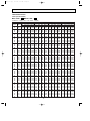
PERFORMANCE DATA
COOL operation(240V)
MCF-13NV -
E4
:MUCF-13NV -
E4
CAPACITY : 3.7(kW) SHF : 0.70 INPUT : 1380(W)
INDOOR INDOOR
DB(;) WB(;)
21
18
21
20
22
18
22
20
22
22
23
18
23
20
23
22
24
18
24
20
24
22
24
24
25
18
25
20
25
22
25
24
26
18
26
20
26
22
26
24
26
26
27
18
27
20
27
22
27
24
27
26
28
18
28
20
28
22
28
24
28
26
29
18
29
20
29
22
29
24
29
26
30
18
30
20
30
22
30
24
30
26
31
18
31
20
31
22
31
24
31
26
32
18
32
20
32
22
32
24
32
26
Q
4.35
4.53
4.35
4.53
4.72
4.35
4.53
4.72
4.35
4.53
4.72
4.96
4.35
4.53
4.72
4.96
4.35
4.53
4.72
4.96
5.11
4.35
4.53
4.72
4.96
5.11
4.35
4.53
4.72
4.96
5.11
4.35
4.53
4.72
4.96
5.11
4.35
4.53
4.72
4.96
5.11
4.35
4.53
4.72
4.96
5.11
4.35
4.53
4.72
4.96
5.11
OUTDOOR DB(;)
21
25
27
30
SHC SHF INPUT Q SHC SHF INPUT Q SHC SHF INPUT Q SHC SHF INPUT
2.26 0.52 1104 4.16 2.16 0.52 1159 4.00 2.08 0.52 1214 3.85 2.00 0.52 1270
1.81 0.40 1159 4.35 1.74 0.40 1228 4.22 1.69 0.40 1256 4.07 1.63 0.40 1311
2.43 0.56 1104 4.16 2.33 0.56 1159 4.00 2.24 0.56 1214 3.85 2.15 0.56 1270
1.99 0.44 1159 4.35 1.91 0.44 1228 4.22 1.86 0.44 1256 4.07 1.79 0.44 1311
1.51 0.32 1201 4.55 1.46 0.32 1277 4.44 1.42 0.32 1311 4.26 1.36 0.32 1366
2.61 0.60 1104 4.16 2.50 0.60 1159 4.00 2.40 0.60 1214 3.85 2.31 0.60 1270
2.18 0.48 1159 4.35 2.09 0.48 1228 4.22 2.02 0.48 1256 4.07 1.95 0.48 1311
1.70 0.36 1201 4.55 1.64 0.36 1277 4.44 1.60 0.36 1311 4.26 1.53 0.36 1366
2.78 0.64 1104 4.16 2.66 0.64 1159 4.00 2.56 0.64 1214 3.85 2.46 0.64 1270
2.36 0.52 1159 4.35 2.26 0.52 1228 4.22 2.19 0.52 1256 4.07 2.12 0.52 1311
1.89 0.40 1201 4.55 1.82 0.40 1277 4.44 1.78 0.40 1311 4.26 1.70 0.40 1366
1.39 0.28 1256 4.77 1.34 0.28 1325 4.66 1.31 0.28 1366 4.51 1.26 0.28 1435
2.96 0.68 1104 4.16 2.83 0.68 1159 4.00 2.72 0.68 1214 3.85 2.62 0.68 1270
2.54 0.56 1159 4.35 2.43 0.56 1228 4.22 2.36 0.56 1256 4.07 2.28 0.56 1311
2.08 0.44 1201 4.55 2.00 0.44 1277 4.44 1.95 0.44 1311 4.26 1.87 0.44 1366
1.59 0.32 1256 4.77 1.53 0.32 1325 4.66 1.49 0.32 1366 4.51 1.44 0.32 1435
3.13 0.72 1104 4.16 3.00 0.72 1159 4.00 2.88 0.72 1214 3.85 2.77 0.72 1270
2.72 0.60 1159 4.35 2.61 0.60 1228 4.22 2.53 0.60 1256 4.07 2.44 0.60 1311
2.26 0.48 1201 4.55 2.18 0.48 1277 4.44 2.13 0.48 1311 4.26 2.04 0.48 1366
1.78 0.36 1256 4.77 1.72 0.36 1325 4.66 1.68 0.36 1366 4.51 1.63 0.36 1435
1.23 0.24 1325 4.96 1.19 0.24 1394 4.88 1.17 0.24 1435 4.74 1.14 0.24 1477
3.30 0.76 1104 4.16 3.16 0.76 1159 4.00 3.04 0.76 1214 3.85 2.92 0.76 1270
2.90 0.64 1159 4.35 2.78 0.64 1228 4.22 2.70 0.64 1256 4.07 2.60 0.64 1311
2.45 0.52 1201 4.55 2.37 0.52 1277 4.44 2.31 0.52 1311 4.26 2.21 0.52 1366
1.98 0.40 1256 4.77 1.91 0.40 1325 4.66 1.86 0.40 1366 4.51 1.81 0.40 1435
1.43 0.28 1325 4.96 1.39 0.28 1394 4.88 1.37 0.28 1435 4.74 1.33 0.28 1477
3.48 0.80 1104 4.16 3.33 0.80 1159 4.00 3.20 0.80 1214 3.85 3.08 0.80 1270
3.08 0.68 1159 4.35 2.96 0.68 1228 4.22 2.87 0.68 1256 4.07 2.77 0.68 1311
2.64 0.56 1201 4.55 2.55 0.56 1277 4.44 2.49 0.56 1311 4.26 2.38 0.56 1366
2.18 0.44 1256 4.77 2.10 0.44 1325 4.66 2.05 0.44 1366 4.51 1.99 0.44 1435
1.63 0.32 1325 4.96 1.59 0.32 1394 4.88 1.56 0.32 1435 4.74 1.52 0.32 1477
3.65 0.84 1104 4.16 3.50 0.84 1159 4.00 3.36 0.84 1214 3.85 3.23 0.84 1270
3.26 0.72 1159 4.35 3.13 0.72 1228 4.22 3.04 0.72 1256 4.07 2.93 0.72 1311
2.83 0.60 1201 4.55 2.73 0.60 1277 4.44 2.66 0.60 1311 4.26 2.55 0.60 1366
2.38 0.48 1256 4.77 2.29 0.48 1325 4.66 2.24 0.48 1366 4.51 2.17 0.48 1435
1.84 0.36 1325 4.96 1.78 0.36 1394 4.88 1.76 0.36 1435 4.74 1.70 0.36 1477
3.83 0.88 1104 4.16 3.66 0.88 1159 4.00 3.52 0.88 1214 3.85 3.39 0.88 1270
3.44 0.76 1159 4.35 3.30 0.76 1228 4.22 3.21 0.76 1256 4.07 3.09 0.76 1311
3.02 0.64 1201 4.55 2.91 0.64 1277 4.44 2.84 0.64 1311 4.26 2.72 0.64 1366
2.58 0.52 1256 4.77 2.48 0.52 1325 4.66 2.42 0.52 1366 4.51 2.35 0.52 1435
2.04 0.40 1325 4.96 1.98 0.40 1394 4.88 1.95 0.40 1435 4.74 1.89 0.40 1477
4.00 0.92 1104 4.16 3.83 0.92 1159 4.00 3.68 0.92 1214 3.85 3.54 0.92 1270
3.63 0.80 1159 4.35 3.48 0.80 1228 4.22 3.37 0.80 1256 4.07 3.26 0.80 1311
3.21 0.68 1201 4.55 3.09 0.68 1277 4.44 3.02 0.68 1311 4.26 2.89 0.68 1366
2.78 0.56 1256 4.77 2.67 0.56 1325 4.66 2.61 0.56 1366 4.51 2.53 0.56 1435
2.25 0.44 1325 4.96 2.18 0.44 1394 4.88 2.15 0.44 1435 4.74 2.08 0.44 1477
4.17 0.96 1104 4.16 4.00 0.96 1159 4.00 3.84 0.96 1214 3.85 3.69 0.96 1270
3.81 0.84 1159 4.35 3.65 0.84 1228 4.22 3.54 0.84 1256 4.07 3.42 0.84 1311
3.40 0.72 1201 4.55 3.28 0.72 1277 4.44 3.20 0.72 1311 4.26 3.06 0.72 1366
2.97 0.60 1256 4.77 2.86 0.60 1325 4.66 2.80 0.60 1366 4.51 2.71 0.60 1435
2.45 0.48 1325 4.96 2.38 0.48 1394 4.88 2.34 0.48 1435 4.74 2.27 0.48 1477
18
OB270--1.qxp
4/13/01 2:59 PM
Page 19
PERFORMANCE DATA
COOL operation(240V)
MCF-13NV -
E4
:MUCF-13NV -
E4
CAPACITY : 3.7(kW) SHF : 0.70 INPUT : 1380(W)
INDOOR INDOOR
DB(;) WB(;)
21
18
21
20
22
18
22
20
22
22
23
18
23
20
23
22
24
18
24
20
24
22
24
24
25
18
25
20
25
22
25
24
26
18
26
20
26
22
26
24
26
26
27
18
27
20
27
22
27
24
27
26
28
18
28
20
28
22
28
24
28
26
29
18
29
20
29
22
29
24
29
26
30
18
30
20
30
22
30
24
30
26
31
18
31
20
31
22
31
24
31
26
32
18
32
20
32
22
32
24
32
26
Q
3.63
3.81
3.63
3.81
4.03
3.63
3.81
4.03
3.63
3.81
4.03
4.26
3.63
3.81
4.03
4.26
3.63
3.81
4.03
4.26
4.48
3.63
3.81
4.03
4.26
4.48
3.63
3.81
4.03
4.26
4.48
3.63
3.81
4.03
4.26
4.48
3.63
3.81
4.03
4.26
4.48
3.63
3.81
4.03
4.26
4.48
3.63
3.81
4.03
4.26
4.48
OUTDOOR DB(;)
35
40
43
46
SHC SHF INPUT Q SHC SHF INPUT Q SHC SHF INPUT Q SHC SHF INPUT
1.89 0.52 1352 3.33 1.73 0.52 1435 3.20 1.66 0.52 1463 3.07 1.60 0.52 1490
1.52 0.40 1408 3.55 1.42 0.40 1477 3.42 1.37 0.40 1518 3.29 1.32 0.40 1559
2.03 0.56 1352 3.33 1.86 0.56 1435 3.20 1.79 0.56 1463 3.07 1.72 0.56 1490
1.68 0.44 1408 3.55 1.56 0.44 1477 3.42 1.51 0.44 1518 3.29 1.45 0.44 1559
1.29 0.32 1463 3.77 1.21 0.32 1546 3.64 1.17 0.32 1573 3.52 1.12 0.32 1601
2.18 0.60 1352 3.33 2.00 0.60 1435 3.20 1.92 0.60 1463 3.07 1.84 0.60 1490
1.83 0.48 1408 3.55 1.70 0.48 1477 3.42 1.64 0.48 1518 3.29 1.58 0.48 1559
1.45 0.36 1463 3.77 1.36 0.36 1546 3.64 1.31 0.36 1573 3.52 1.27 0.36 1601
2.32 0.64 1352 3.33 2.13 0.64 1435 3.20 2.05 0.64 1463 3.07 1.97 0.64 1490
1.98 0.52 1408 3.55 1.85 0.52 1477 3.42 1.78 0.52 1518 3.29 1.71 0.52 1559
1.61 0.40 1463 3.77 1.51 0.40 1546 3.64 1.46 0.40 1573 3.52 1.41 0.40 1601
1.19 0.28 1518 4.00 1.12 0.28 1587 3.89 1.09 0.28 1622 3.77 1.06 0.28 1656
2.47 0.68 1352 3.33 2.26 0.68 1435 3.20 2.18 0.68 1463 3.07 2.09 0.68 1490
2.13 0.56 1408 3.55 1.99 0.56 1477 3.42 1.92 0.56 1518 3.29 1.84 0.56 1559
1.77 0.44 1463 3.77 1.66 0.44 1546 3.64 1.60 0.44 1573 3.52 1.55 0.44 1601
1.36 0.32 1518 4.00 1.28 0.32 1587 3.89 1.24 0.32 1622 3.77 1.21 0.32 1656
2.61 0.72 1352 3.33 2.40 0.72 1435 3.20 2.30 0.72 1463 3.07 2.21 0.72 1490
2.29 0.60 1408 3.55 2.13 0.60 1477 3.42 2.05 0.60 1518 3.29 1.98 0.60 1559
1.94 0.48 1463 3.77 1.81 0.48 1546 3.64 1.75 0.48 1573 3.52 1.69 0.48 1601
1.53 0.36 1518 4.00 1.44 0.36 1587 3.89 1.40 0.36 1622 3.77 1.36 0.36 1656
1.07 0.24 1573 4.22 1.01 0.24 1642 4.09 0.98 0.24 1677 3.96 0.95 0.24 1711
2.76 0.76 1352 3.33 2.53 0.76 1435 3.20 2.43 0.76 1463 3.07 2.33 0.76 1490
2.44 0.64 1408 3.55 2.27 0.64 1477 3.42 2.19 0.64 1518 3.29 2.11 0.64 1559
2.10 0.52 1463 3.77 1.96 0.52 1546 3.64 1.90 0.52 1573 3.52 1.83 0.52 1601
1.70 0.40 1518 4.00 1.60 0.40 1587 3.89 1.55 0.40 1622 3.77 1.51 0.40 1656
1.25 0.28 1573 4.22 1.18 0.28 1642 4.09 1.14 0.28 1677 3.96 1.11 0.28 1711
2.90 0.80 1352 3.33 2.66 0.80 1435 3.20 2.56 0.80 1463 3.07 2.46 0.80 1490
2.59 0.68 1408 3.55 2.42 0.68 1477 3.42 2.33 0.68 1518 3.29 2.24 0.68 1559
2.26 0.56 1463 3.77 2.11 0.56 1546 3.64 2.04 0.56 1573 3.52 1.97 0.56 1601
1.87 0.44 1518 4.00 1.76 0.44 1587 3.89 1.71 0.44 1622 3.77 1.66 0.44 1656
1.43 0.32 1573 4.22 1.35 0.32 1642 4.09 1.31 0.32 1677 3.96 1.27 0.32 1711
3.05 0.84 1352 3.33 2.80 0.84 1435 3.20 2.69 0.84 1463 3.07 2.58 0.84 1490
2.74 0.72 1408 3.55 2.56 0.72 1477 3.42 2.46 0.72 1518 3.29 2.37 0.72 1559
2.42 0.60 1463 3.77 2.26 0.60 1546 3.64 2.19 0.60 1573 3.52 2.11 0.60 1601
2.04 0.48 1518 4.00 1.92 0.48 1587 3.89 1.86 0.48 1622 3.77 1.81 0.48 1656
1.61 0.36 1573 4.22 1.52 0.36 1642 4.09 1.47 0.36 1677 3.96 1.43 0.36 1711
3.19 0.88 1352 3.33 2.93 0.88 1435 3.20 2.82 0.88 1463 3.07 2.70 0.88 1490
2.90 0.76 1408 3.55 2.70 0.76 1477 3.42 2.60 0.76 1518 3.29 2.50 0.76 1559
2.58 0.64 1463 3.77 2.42 0.64 1546 3.64 2.33 0.64 1573 3.52 2.25 0.64 1601
2.21 0.52 1518 4.00 2.08 0.52 1587 3.89 2.02 0.52 1622 3.77 1.96 0.52 1656
1.79 0.40 1573 4.22 1.69 0.40 1642 4.09 1.64 0.40 1677 3.96 1.58 0.40 1711
3.34 0.92 1352 3.33 3.06 0.92 1435 3.20 2.94 0.92 1463 3.07 2.83 0.92 1490
3.05 0.80 1408 3.55 2.84 0.80 1477 3.42 2.74 0.80 1518 3.29 2.63 0.80 1559
2.74 0.68 1463 3.77 2.57 0.68 1546 3.64 2.48 0.68 1573 3.52 2.39 0.68 1601
2.38 0.56 1518 4.00 2.24 0.56 1587 3.89 2.18 0.56 1622 3.77 2.11 0.56 1656
1.97 0.44 1573 4.22 1.86 0.44 1642 4.09 1.80 0.44 1677 3.96 1.74 0.44 1711
3.48 0.96 1352 3.33 3.20 0.96 1435 3.20 3.07 0.96 1463 3.07 2.95 0.96 1490
3.20 0.84 1408 3.55 2.98 0.84 1477 3.42 2.87 0.84 1518 3.29 2.77 0.84 1559
2.90 0.72 1463 3.77 2.72 0.72 1546 3.64 2.62 0.72 1573 3.52 2.53 0.72 1601
2.55 0.60 1518 4.00 2.40 0.60 1587 3.89 2.33 0.60 1622 3.77 2.26 0.60 1656
2.15 0.48 1573 4.22 2.02 0.48 1642 4.09 1.96 0.48 1677 3.96 1.90 0.48 1711
19
OB270--1.qxp
4/13/01 2:59 PM
Page 20
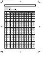
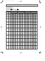
PERFORMANCE DATA
COOL operation(220V)
MCF-18NV -
E3
:MUCF-18NV -
E3
CAPACITY : 5.0(kW) SHF : 0.67 INPUT : 1920(W)
OUTDOOR DB(;)
INDOOR INDOOR
DB(;) WB(;)
21
18
21
20
22
18
22
20
22
22
23
18
23
20
23
22
24
18
24
20
24
22
24
24
25
18
25
20
25
22
25
24
26
18
26
20
26
22
26
24
26
26
27
18
27
20
27
22
27
24
27
26
28
18
28
20
28
22
28
24
28
26
29
18
29
20
29
22
29
24
29
26
30
18
30
20
30
22
30
24
30
26
31
18
31
20
31
22
31
24
31
26
32
18
32
20
32
22
32
24
32
26
Q
5.88
6.13
5.88
6.13
6.38
5.88
6.13
6.38
5.88
6.13
6.38
6.70
5.88
6.13
6.38
6.70
5.88
6.13
6.38
6.70
6.90
5.88
6.13
6.38
6.70
6.90
5.88
6.13
6.38
6.70
6.90
5.88
6.13
6.38
6.70
6.90
5.88
6.13
6.38
6.70
6.90
5.88
6.13
6.38
6.70
6.90
5.88
6.13
6.38
6.70
6.90
21
25
27
30
SHC SHF INPUT Q SHC SHF INPUT Q SHC SHF INPUT Q SHC SHF INPUT
2.88 0.49 1536 5.63 2.76 0.49 1613 5.40 2.65 0.49 1690 5.20 2.55 0.49 1766
2.27 0.37 1613 5.88 2.17 0.37 1709 5.70 2.11 0.37 1747 5.50 2.04 0.37 1824
3.11 0.53 1536 5.63 2.98 0.53 1613 5.40 2.86 0.53 1690 5.20 2.76 0.53 1766
2.51 0.41 1613 5.88 2.41 0.41 1709 5.70 2.34 0.41 1747 5.50 2.26 0.41 1824
1.85 0.29 1670 6.15 1.78 0.29 1776 6.00 1.74 0.29 1824 5.75 1.67 0.29 1901
3.35 0.57 1536 5.63 3.21 0.57 1613 5.40 3.08 0.57 1690 5.20 2.96 0.57 1766
2.76 0.45 1613 5.88 2.64 0.45 1709 5.70 2.57 0.45 1747 5.50 2.48 0.45 1824
2.10 0.33 1670 6.15 2.03 0.33 1776 6.00 1.98 0.33 1824 5.75 1.90 0.33 1901
3.58 0.61 1536 5.63 3.43 0.61 1613 5.40 3.29 0.61 1690 5.20 3.17 0.61 1766
3.00 0.49 1613 5.88 2.88 0.49 1709 5.70 2.79 0.49 1747 5.50 2.70 0.49 1824
2.36 0.37 1670 6.15 2.28 0.37 1776 6.00 2.22 0.37 1824 5.75 2.13 0.37 1901
1.68 0.25 1747 6.45 1.61 0.25 1843 6.30 1.58 0.25 1901 6.10 1.53 0.25 1997
3.82 0.65 1536 5.63 3.66 0.65 1613 5.40 3.51 0.65 1690 5.20 3.38 0.65 1766
3.25 0.53 1613 5.88 3.11 0.53 1709 5.70 3.02 0.53 1747 5.50 2.92 0.53 1824
2.61 0.41 1670 6.15 2.52 0.41 1776 6.00 2.46 0.41 1824 5.75 2.36 0.41 1901
1.94 0.29 1747 6.45 1.87 0.29 1843 6.30 1.83 0.29 1901 6.10 1.77 0.29 1997
4.05 0.69 1536 5.63 3.88 0.69 1613 5.40 3.73 0.69 1690 5.20 3.59 0.69 1766
3.49 0.57 1613 5.88 3.35 0.57 1709 5.70 3.25 0.57 1747 5.50 3.14 0.57 1824
2.87 0.45 1670 6.15 2.77 0.45 1776 6.00 2.70 0.45 1824 5.75 2.59 0.45 1901
2.21 0.33 1747 6.45 2.13 0.33 1843 6.30 2.08 0.33 1901 6.10 2.01 0.33 1997
1.45 0.21 1843 6.70 1.41 0.21 1939 6.60 1.39 0.21 1997 6.40 1.34 0.21 2054
4.29 0.73 1536 5.63 4.11 0.73 1613 5.40 3.94 0.73 1690 5.20 3.80 0.73 1766
3.74 0.61 1613 5.88 3.58 0.61 1709 5.70 3.48 0.61 1747 5.50 3.36 0.61 1824
3.12 0.49 1670 6.15 3.01 0.49 1776 6.00 2.94 0.49 1824 5.75 2.82 0.49 1901
2.48 0.37 1747 6.45 2.39 0.37 1843 6.30 2.33 0.37 1901 6.10 2.26 0.37 1997
1.73 0.25 1843 6.70 1.68 0.25 1939 6.60 1.65 0.25 1997 6.40 1.60 0.25 2054
4.52 0.77 1536 5.63 4.33 0.77 1613 5.40 4.16 0.77 1690 5.20 4.00 0.77 1766
3.98 0.65 1613 5.88 3.82 0.65 1709 5.70 3.71 0.65 1747 5.50 3.58 0.65 1824
3.38 0.53 1670 6.15 3.26 0.53 1776 6.00 3.18 0.53 1824 5.75 3.05 0.53 1901
2.75 0.41 1747 6.45 2.64 0.41 1843 6.30 2.58 0.41 1901 6.10 2.50 0.41 1997
2.00 0.29 1843 6.70 1.94 0.29 1939 6.60 1.91 0.29 1997 6.40 1.86 0.29 2054
4.76 0.81 1536 5.63 4.56 0.81 1613 5.40 4.37 0.81 1690 5.20 4.21 0.81 1766
4.23 0.69 1613 5.88 4.05 0.69 1709 5.70 3.93 0.69 1747 5.50 3.80 0.69 1824
3.63 0.57 1670 6.15 3.51 0.57 1776 6.00 3.42 0.57 1824 5.75 3.28 0.57 1901
3.02 0.45 1747 6.45 2.90 0.45 1843 6.30 2.84 0.45 1901 6.10 2.75 0.45 1997
2.28 0.33 1843 6.70 2.21 0.33 1939 6.60 2.18 0.33 1997 6.40 2.11 0.33 2054
4.99 0.85 1536 5.63 4.78 0.85 1613 5.40 4.59 0.85 1690 5.20 4.42 0.85 1766
4.47 0.73 1613 5.88 4.29 0.73 1709 5.70 4.16 0.73 1747 5.50 4.02 0.73 1824
3.89 0.61 1670 6.15 3.75 0.61 1776 6.00 3.66 0.61 1824 5.75 3.51 0.61 1901
3.28 0.49 1747 6.45 3.16 0.49 1843 6.30 3.09 0.49 1901 6.10 2.99 0.49 1997
2.55 0.37 1843 6.70 2.48 0.37 1939 6.60 2.44 0.37 1997 6.40 2.37 0.37 2054
5.23 0.89 1536 5.63 5.01 0.89 1613 5.40 4.81 0.89 1690 5.20 4.63 0.89 1766
4.72 0.77 1613 5.88 4.52 0.77 1709 5.70 4.39 0.77 1747 5.50 4.24 0.77 1824
4.14 0.65 1670 6.15 4.00 0.65 1776 6.00 3.90 0.65 1824 5.75 3.74 0.65 1901
3.55 0.53 1747 6.45 3.42 0.53 1843 6.30 3.34 0.53 1901 6.10 3.23 0.53 1997
2.83 0.41 1843 6.70 2.75 0.41 1939 6.60 2.71 0.41 1997 6.40 2.62 0.41 2054
5.46 0.93 1536 5.63 5.23 0.93 1613 5.40 5.02 0.93 1690 5.20 4.84 0.93 1766
4.96 0.81 1613 5.88 4.76 0.81 1709 5.70 4.62 0.81 1747 5.50 4.46 0.81 1824
4.40 0.69 1670 6.15 4.24 0.69 1776 6.00 4.14 0.69 1824 5.75 3.97 0.69 1901
3.82 0.57 1747 6.45 3.68 0.57 1843 6.30 3.59 0.57 1901 6.10 3.48 0.57 1997
3.11 0.45 1843 6.70 3.02 0.45 1939 6.60 2.97 0.45 1997 6.40 2.88 0.45 2054
20
OB270--1.qxp
4/13/01 2:59 PM
Page 21
PERFORMANCE DATA
COOL operation(220V)
MCF-18NV -
E3
:MUCF-18NV -
E3
CAPACITY : 5.0(kW) SHF : 0.67 INPUT : 1920(W)
INDOOR INDOOR
DB(;) WB(;)
21
18
21
20
22
18
22
20
22
22
23
18
23
20
23
22
24
18
24
20
24
22
24
24
25
18
25
20
25
22
25
24
26
18
26
20
26
22
26
24
26
26
27
18
27
20
27
22
27
24
27
26
28
18
28
20
28
22
28
24
28
26
29
18
29
20
29
22
29
24
29
26
30
18
30
20
30
22
30
24
30
26
31
18
31
20
31
22
31
24
31
26
32
18
32
20
32
22
32
24
32
26
Q
4.90
5.15
4.90
5.15
5.45
4.90
5.15
5.45
4.90
5.15
5.45
5.75
4.90
5.15
5.45
5.75
4.90
5.15
5.45
5.75
6.05
4.90
5.15
5.45
5.75
6.05
4.90
5.15
5.45
5.75
6.05
4.90
5.15
5.45
5.75
6.05
4.90
5.15
5.45
5.75
6.05
4.90
5.15
5.45
5.75
6.05
4.90
5.15
5.45
5.75
6.05
OUTDOOR DB(;)
35
40
43
46
SHC SHF INPUT Q SHC SHF INPUT Q SHC SHF INPUT Q SHC SHF INPUT
2.40 0.49 1882 4.50 2.21 0.49 1997 4.33 2.12 0.49 2035 4.15 2.03 0.49 2074
1.91 0.37 1958 4.80 1.78 0.37 2054 4.63 1.71 0.37 2112 4.45 1.65 0.37 2170
2.60 0.53 1882 4.50 2.39 0.53 1997 4.33 2.29 0.53 2035 4.15 2.20 0.53 2074
2.11 0.41 1958 4.80 1.97 0.41 2054 4.63 1.90 0.41 2112 4.45 1.82 0.41 2170
1.58 0.29 2035 5.10 1.48 0.29 2150 4.93 1.43 0.29 2189 4.75 1.38 0.29 2227
2.79 0.57 1882 4.50 2.57 0.57 1997 4.33 2.47 0.57 2035 4.15 2.37 0.57 2074
2.32 0.45 1958 4.80 2.16 0.45 2054 4.63 2.08 0.45 2112 4.45 2.00 0.45 2170
1.80 0.33 2035 5.10 1.68 0.33 2150 4.93 1.63 0.33 2189 4.75 1.57 0.33 2227
2.99 0.61 1882 4.50 2.75 0.61 1997 4.33 2.64 0.61 2035 4.15 2.53 0.61 2074
2.52 0.49 1958 4.80 2.35 0.49 2054 4.63 2.27 0.49 2112 4.45 2.18 0.49 2170
2.02 0.37 2035 5.10 1.89 0.37 2150 4.93 1.82 0.37 2189 4.75 1.76 0.37 2227
1.44 0.25 2112 5.40 1.35 0.25 2208 5.25 1.31 0.25 2256 5.10 1.28 0.25 2304
3.19 0.65 1882 4.50 2.93 0.65 1997 4.33 2.81 0.65 2035 4.15 2.70 0.65 2074
2.73 0.53 1958 4.80 2.54 0.53 2054 4.63 2.45 0.53 2112 4.45 2.36 0.53 2170
2.23 0.41 2035 5.10 2.09 0.41 2150 4.93 2.02 0.41 2189 4.75 1.95 0.41 2227
1.67 0.29 2112 5.40 1.57 0.29 2208 5.25 1.52 0.29 2256 5.10 1.48 0.29 2304
3.38 0.69 1882 4.50 3.11 0.69 1997 4.33 2.98 0.69 2035 4.15 2.86 0.69 2074
2.94 0.57 1958 4.80 2.74 0.57 2054 4.63 2.64 0.57 2112 4.45 2.54 0.57 2170
2.45 0.45 2035 5.10 2.30 0.45 2150 4.93 2.22 0.45 2189 4.75 2.14 0.45 2227
1.90 0.33 2112 5.40 1.78 0.33 2208 5.25 1.73 0.33 2256 5.10 1.68 0.33 2304
1.27 0.21 2189 5.70 1.20 0.21 2285 5.53 1.16 0.21 2333 5.35 1.12 0.21 2381
3.58 0.73 1882 4.50 3.29 0.73 1997 4.33 3.16 0.73 2035 4.15 3.03 0.73 2074
3.14 0.61 1958 4.80 2.93 0.61 2054 4.63 2.82 0.61 2112 4.45 2.71 0.61 2170
2.67 0.49 2035 5.10 2.50 0.49 2150 4.93 2.41 0.49 2189 4.75 2.33 0.49 2227
2.13 0.37 2112 5.40 2.00 0.37 2208 5.25 1.94 0.37 2256 5.10 1.89 0.37 2304
1.51 0.25 2189 5.70 1.43 0.25 2285 5.53 1.38 0.25 2333 5.35 1.34 0.25 2381
3.77 0.77 1882 4.50 3.47 0.77 1997 4.33 3.33 0.77 2035 4.15 3.20 0.77 2074
3.35 0.65 1958 4.80 3.12 0.65 2054 4.63 3.01 0.65 2112 4.45 2.89 0.65 2170
2.89 0.53 2035 5.10 2.70 0.53 2150 4.93 2.61 0.53 2189 4.75 2.52 0.53 2227
2.36 0.41 2112 5.40 2.21 0.41 2208 5.25 2.15 0.41 2256 5.10 2.09 0.41 2304
1.75 0.29 2189 5.70 1.65 0.29 2285 5.53 1.60 0.29 2333 5.35 1.55 0.29 2381
3.97 0.81 1882 4.50 3.65 0.81 1997 4.33 3.50 0.81 2035 4.15 3.36 0.81 2074
3.55 0.69 1958 4.80 3.31 0.69 2054 4.63 3.19 0.69 2112 4.45 3.07 0.69 2170
3.11 0.57 2035 5.10 2.91 0.57 2150 4.93 2.81 0.57 2189 4.75 2.71 0.57 2227
2.59 0.45 2112 5.40 2.43 0.45 2208 5.25 2.36 0.45 2256 5.10 2.30 0.45 2304
2.00 0.33 2189 5.70 1.88 0.33 2285 5.53 1.82 0.33 2333 5.35 1.77 0.33 2381
4.17 0.85 1882 4.50 3.83 0.85 1997 4.33 3.68 0.85 2035 4.15 3.53 0.85 2074
3.76 0.73 1958 4.80 3.50 0.73 2054 4.63 3.38 0.73 2112 4.45 3.25 0.73 2170
3.32 0.61 2035 5.10 3.11 0.61 2150 4.93 3.00 0.61 2189 4.75 2.90 0.61 2227
2.82 0.49 2112 5.40 2.65 0.49 2208 5.25 2.57 0.49 2256 5.10 2.50 0.49 2304
2.24 0.37 2189 5.70 2.11 0.37 2285 5.53 2.04 0.37 2333 5.35 1.98 0.37 2381
4.36 0.89 1882 4.50 4.01 0.89 1997 4.33 3.85 0.89 2035 4.15 3.69 0.89 2074
3.97 0.77 1958 4.80 3.70 0.77 2054 4.63 3.56 0.77 2112 4.45 3.43 0.77 2170
3.54 0.65 2035 5.10 3.32 0.65 2150 4.93 3.20 0.65 2189 4.75 3.09 0.65 2227
3.05 0.53 2112 5.40 2.86 0.53 2208 5.25 2.78 0.53 2256 5.10 2.70 0.53 2304
2.48 0.41 2189 5.70 2.34 0.41 2285 5.53 2.27 0.41 2333 5.35 2.19 0.41 2381
4.56 0.93 1882 4.50 4.19 0.93 1997 4.33 4.02 0.93 2035 4.15 3.86 0.93 2074
4.17 0.81 1958 4.80 3.89 0.81 2054 4.63 3.75 0.81 2112 4.45 3.60 0.81 2170
3.76 0.69 2035 5.10 3.52 0.69 2150 4.93 3.40 0.69 2189 4.75 3.28 0.69 2227
3.28 0.57 2112 5.40 3.08 0.57 2208 5.25 2.99 0.57 2256 5.10 2.91 0.57 2304
2.72 0.45 2189 5.70 2.57 0.45 2285 5.53 2.49 0.45 2333 5.35 2.41 0.45 2381
21
OB270--1.qxp
4/13/01 2:59 PM
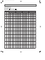
Page 22
PERFORMANCE DATA
COOL operation(240V)
MCF-18NV -
E3
:MUCF-18NV -
E3
CAPACITY : 5.0(kW) SHF : 0.67 INPUT : 2010(W)
OUTDOOR DB(;)
INDOOR INDOOR
DB(;) WB(;)
21
18
21
20
22
18
22
20
22
22
23
18
23
20
23
22
24
18
24
20
24
22
24
24
25
18
25
20
25
22
25
24
26
18
26
20
26
22
26
24
26
26
27
18
27
20
27
22
27
24
27
26
28
18
28
20
28
22
28
24
28
26
29
18
29
20
29
22
29
24
29
26
30
18
30
20
30
22
30
24
30
26
31
18
31
20
31
22
31
24
31
26
32
18
32
20
32
22
32
24
32
26
Q
5.88
6.13
5.88
6.13
6.38
5.88
6.13
6.38
5.88
6.13
6.38
6.70
5.88
6.13
6.38
6.70
5.88
6.13
6.38
6.70
6.90
5.88
6.13
6.38
6.70
6.90
5.88
6.13
6.38
6.70
6.90
5.88
6.13
6.38
6.70
6.90
5.88
6.13
6.38
6.70
6.90
5.88
6.13
6.38
6.70
6.90
5.88
6.13
6.38
6.70
6.90
SHC
2.88
2.27
3.11
2.51
1.85
3.35
2.76
2.10
3.58
3.00
2.36
1.68
3.82
3.25
2.61
1.94
4.05
3.49
2.87
2.21
1.45
4.29
3.74
3.12
2.48
1.73
4.52
3.98
3.38
2.75
2.00
4.76
4.23
3.63
3.02
2.28
4.99
4.47
3.89
3.28
2.55
5.23
4.72
4.14
3.55
2.83
5.46
4.96
4.40
3.82
3.11
21
25
27
30
SHF INPUT Q SHC SHF INPUT Q SHC SHF INPUT Q SHC SHF INPUT
0.49 1608 5.63 2.76 0.49 1688 5.40 2.65 0.49 1769 5.20 2.55 0.49 1849
0.37 1688 5.88 2.17 0.37 1789 5.70 2.11 0.37 1829 5.50 2.04 0.37 1910
0.53 1608 5.63 2.98 0.53 1688 5.40 2.86 0.53 1769 5.20 2.76 0.53 1849
0.41 1688 5.88 2.41 0.41 1789 5.70 2.34 0.41 1829 5.50 2.26 0.41 1910
0.29 1749 6.15 1.78 0.29 1859 6.00 1.74 0.29 1910 5.75 1.67 0.29 1990
0.57 1608 5.63 3.21 0.57 1688 5.40 3.08 0.57 1769 5.20 2.96 0.57 1849
0.45 1688 5.88 2.64 0.45 1789 5.70 2.57 0.45 1829 5.50 2.48 0.45 1910
0.33 1749 6.15 2.03 0.33 1859 6.00 1.98 0.33 1910 5.75 1.90 0.33 1990
0.61 1608 5.63 3.43 0.61 1688 5.40 3.29 0.61 1769 5.20 3.17 0.61 1849
0.49 1688 5.88 2.88 0.49 1789 5.70 2.79 0.49 1829 5.50 2.70 0.49 1910
0.37 1749 6.15 2.28 0.37 1859 6.00 2.22 0.37 1910 5.75 2.13 0.37 1990
0.25 1829 6.45 1.61 0.25 1930 6.30 1.58 0.25 1990 6.10 1.53 0.25 2090
0.65 1608 5.63 3.66 0.65 1688 5.40 3.51 0.65 1769 5.20 3.38 0.65 1849
0.53 1688 5.88 3.11 0.53 1789 5.70 3.02 0.53 1829 5.50 2.92 0.53 1910
0.41 1749 6.15 2.52 0.41 1859 6.00 2.46 0.41 1910 5.75 2.36 0.41 1990
0.29 1829 6.45 1.87 0.29 1930 6.30 1.83 0.29 1990 6.10 1.77 0.29 2090
0.69 1608 5.63 3.88 0.69 1688 5.40 3.73 0.69 1769 5.20 3.59 0.69 1849
0.57 1688 5.88 3.35 0.57 1789 5.70 3.25 0.57 1829 5.50 3.14 0.57 1910
0.45 1749 6.15 2.77 0.45 1859 6.00 2.70 0.45 1910 5.75 2.59 0.45 1990
0.33 1829 6.45 2.13 0.33 1930 6.30 2.08 0.33 1990 6.10 2.01 0.33 2090
0.21 1930 6.70 1.41 0.21 2030 6.60 1.39 0.21 2090 6.40 1.34 0.21 2151
0.73 1608 5.63 4.11 0.73 1688 5.40 3.94 0.73 1769 5.20 3.80 0.73 1849
0.61 1688 5.88 3.58 0.61 1789 5.70 3.48 0.61 1829 5.50 3.36 0.61 1910
0.49 1749 6.15 3.01 0.49 1859 6.00 2.94 0.49 1910 5.75 2.82 0.49 1990
0.37 1829 6.45 2.39 0.37 1930 6.30 2.33 0.37 1990 6.10 2.26 0.37 2090
0.25 1930 6.70 1.68 0.25 2030 6.60 1.65 0.25 2090 6.40 1.60 0.25 2151
0.77 1608 5.63 4.33 0.77 1688 5.40 4.16 0.77 1769 5.20 4.00 0.77 1849
0.65 1688 5.88 3.82 0.65 1789 5.70 3.71 0.65 1829 5.50 3.58 0.65 1910
0.53 1749 6.15 3.26 0.53 1859 6.00 3.18 0.53 1910 5.75 3.05 0.53 1990
0.41 1829 6.45 2.64 0.41 1930 6.30 2.58 0.41 1990 6.10 2.50 0.41 2090
0.29 1930 6.70 1.94 0.29 2030 6.60 1.91 0.29 2090 6.40 1.86 0.29 2151
0.81 1608 5.63 4.56 0.81 1688 5.40 4.37 0.81 1769 5.20 4.21 0.81 1849
0.69 1688 5.88 4.05 0.69 1789 5.70 3.93 0.69 1829 5.50 3.80 0.69 1910
0.57 1749 6.15 3.51 0.57 1859 6.00 3.42 0.57 1910 5.75 3.28 0.57 1990
0.45 1829 6.45 2.90 0.45 1930 6.30 2.84 0.45 1990 6.10 2.75 0.45 2090
0.33 1930 6.70 2.21 0.33 2030 6.60 2.18 0.33 2090 6.40 2.11 0.33 2151
0.85 1608 5.63 4.78 0.85 1688 5.40 4.59 0.85 1769 5.20 4.42 0.85 1849
0.73 1688 5.88 4.29 0.73 1789 5.70 4.16 0.73 1829 5.50 4.02 0.73 1910
0.61 1749 6.15 3.75 0.61 1859 6.00 3.66 0.61 1910 5.75 3.51 0.61 1990
0.49 1829 6.45 3.16 0.49 1930 6.30 3.09 0.49 1990 6.10 2.99 0.49 2090
0.37 1930 6.70 2.48 0.37 2030 6.60 2.44 0.37 2090 6.40 2.37 0.37 2151
0.89 1608 5.63 5.01 0.89 1688 5.40 4.81 0.89 1769 5.20 4.63 0.89 1849
0.77 1688 5.88 4.52 0.77 1789 5.70 4.39 0.77 1829 5.50 4.24 0.77 1910
0.65 1749 6.15 4.00 0.65 1859 6.00 3.90 0.65 1910 5.75 3.74 0.65 1990
0.53 1829 6.45 3.42 0.53 1930 6.30 3.34 0.53 1990 6.10 3.23 0.53 2090
0.41 1930 6.70 2.75 0.41 2030 6.60 2.71 0.41 2090 6.40 2.62 0.41 2151
0.93 1608 5.63 5.23 0.93 1688 5.40 5.02 0.93 1769 5.20 4.84 0.93 1849
0.81 1688 5.88 4.76 0.81 1789 5.70 4.62 0.81 1829 5.50 4.46 0.81 1910
0.69 1749 6.15 4.24 0.69 1859 6.00 4.14 0.69 1910 5.75 3.97 0.69 1990
0.57 1829 6.45 3.68 0.57 1930 6.30 3.59 0.57 1990 6.10 3.48 0.57 2090
0.45 1930 6.70 3.02 0.45 2030 6.60 2.97 0.45 2090 6.40 2.88 0.45 2151
22
OB270--1.qxp
4/13/01 2:59 PM
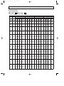
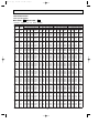
Page 23
PERFORMANCE DATA
COOL operation(240V)
MCF-18NV -
E3
:MUCF-18NV -
E3
CAPACITY : 5.0(kW) SHF : 0.67 INPUT : 2010(W)
OUTDOOR DB(;)
INDOOR INDOOR
DB(;) WB(;)
21
18
21
20
22
18
22
20
22
22
23
18
23
20
23
22
24
18
24
20
24
22
24
24
25
18
25
20
25
22
25
24
26
18
26
20
26
22
26
24
26
26
27
18
27
20
27
22
27
24
27
26
28
18
28
20
28
22
28
24
28
26
29
18
29
20
29
22
29
24
29
26
30
18
30
20
30
22
30
24
30
26
31
18
31
20
31
22
31
24
31
26
32
18
32
20
32
22
32
24
32
26
Q
4.90
5.15
4.90
5.15
5.45
4.90
5.15
5.45
4.90
5.15
5.45
5.75
4.90
5.15
5.45
5.75
4.90
5.15
5.45
5.75
6.05
4.90
5.15
5.45
5.75
6.05
4.90
5.15
5.45
5.75
6.05
4.90
5.15
5.45
5.75
6.05
4.90
5.15
5.45
5.75
6.05
4.90
5.15
5.45
5.75
6.05
4.90
5.15
5.45
5.75
6.05
35
40
43
46
SHC SHF INPUT Q SHC SHF INPUT Q SHC SHF INPUT Q SHC SHF INPUT
2.40 0.49 1970 4.50 2.21 0.49 2090 4.33 2.12 0.49 2131 4.15 2.03 0.49 2171
1.91 0.37 2050 4.80 1.78 0.37 2151 4.63 1.71 0.37 2211 4.45 1.65 0.37 2271
2.60 0.53 1970 4.50 2.39 0.53 2090 4.33 2.29 0.53 2131 4.15 2.20 0.53 2171
2.11 0.41 2050 4.80 1.97 0.41 2151 4.63 1.90 0.41 2211 4.45 1.82 0.41 2271
1.58 0.29 2131 5.10 1.48 0.29 2251 4.93 1.43 0.29 2291 4.75 1.38 0.29 2332
2.79 0.57 1970 4.50 2.57 0.57 2090 4.33 2.47 0.57 2131 4.15 2.37 0.57 2171
2.32 0.45 2050 4.80 2.16 0.45 2151 4.63 2.08 0.45 2211 4.45 2.00 0.45 2271
1.80 0.33 2131 5.10 1.68 0.33 2251 4.93 1.63 0.33 2291 4.75 1.57 0.33 2332
2.99 0.61 1970 4.50 2.75 0.61 2090 4.33 2.64 0.61 2131 4.15 2.53 0.61 2171
2.52 0.49 2050 4.80 2.35 0.49 2151 4.63 2.27 0.49 2211 4.45 2.18 0.49 2271
2.02 0.37 2131 5.10 1.89 0.37 2251 4.93 1.82 0.37 2291 4.75 1.76 0.37 2332
1.44 0.25 2211 5.40 1.35 0.25 2312 5.25 1.31 0.25 2362 5.10 1.28 0.25 2412
3.19 0.65 1970 4.50 2.93 0.65 2090 4.33 2.81 0.65 2131 4.15 2.70 0.65 2171
2.73 0.53 2050 4.80 2.54 0.53 2151 4.63 2.45 0.53 2211 4.45 2.36 0.53 2271
2.23 0.41 2131 5.10 2.09 0.41 2251 4.93 2.02 0.41 2291 4.75 1.95 0.41 2332
1.67 0.29 2211 5.40 1.57 0.29 2312 5.25 1.52 0.29 2362 5.10 1.48 0.29 2412
3.38 0.69 1970 4.50 3.11 0.69 2090 4.33 2.98 0.69 2131 4.15 2.86 0.69 2171
2.94 0.57 2050 4.80 2.74 0.57 2151 4.63 2.64 0.57 2211 4.45 2.54 0.57 2271
2.45 0.45 2131 5.10 2.30 0.45 2251 4.93 2.22 0.45 2291 4.75 2.14 0.45 2332
1.90 0.33 2211 5.40 1.78 0.33 2312 5.25 1.73 0.33 2362 5.10 1.68 0.33 2412
1.27 0.21 2291 5.70 1.20 0.21 2392 5.53 1.16 0.21 2442 5.35 1.12 0.21 2492
3.58 0.73 1970 4.50 3.29 0.73 2090 4.33 3.16 0.73 2131 4.15 3.03 0.73 2171
3.14 0.61 2050 4.80 2.93 0.61 2151 4.63 2.82 0.61 2211 4.45 2.71 0.61 2271
2.67 0.49 2131 5.10 2.50 0.49 2251 4.93 2.41 0.49 2291 4.75 2.33 0.49 2332
2.13 0.37 2211 5.40 2.00 0.37 2312 5.25 1.94 0.37 2362 5.10 1.89 0.37 2412
1.51 0.25 2291 5.70 1.43 0.25 2392 5.53 1.38 0.25 2442 5.35 1.34 0.25 2492
3.77 0.77 1970 4.50 3.47 0.77 2090 4.33 3.33 0.77 2131 4.15 3.20 0.77 2171
3.35 0.65 2050 4.80 3.12 0.65 2151 4.63 3.01 0.65 2211 4.45 2.89 0.65 2271
2.89 0.53 2131 5.10 2.70 0.53 2251 4.93 2.61 0.53 2291 4.75 2.52 0.53 2332
2.36 0.41 2211 5.40 2.21 0.41 2312 5.25 2.15 0.41 2362 5.10 2.09 0.41 2412
1.75 0.29 2291 5.70 1.65 0.29 2392 5.53 1.60 0.29 2442 5.35 1.55 0.29 2492
3.97 0.81 1970 4.50 3.65 0.81 2090 4.33 3.50 0.81 2131 4.15 3.36 0.81 2171
3.55 0.69 2050 4.80 3.31 0.69 2151 4.63 3.19 0.69 2211 4.45 3.07 0.69 2271
3.11 0.57 2131 5.10 2.91 0.57 2251 4.93 2.81 0.57 2291 4.75 2.71 0.57 2332
2.59 0.45 2211 5.40 2.43 0.45 2312 5.25 2.36 0.45 2362 5.10 2.30 0.45 2412
2.00 0.33 2291 5.70 1.88 0.33 2392 5.53 1.82 0.33 2442 5.35 1.77 0.33 2492
4.17 0.85 1970 4.50 3.83 0.85 2090 4.33 3.68 0.85 2131 4.15 3.53 0.85 2171
3.76 0.73 2050 4.80 3.50 0.73 2151 4.63 3.38 0.73 2211 4.45 3.25 0.73 2271
3.32 0.61 2131 5.10 3.11 0.61 2251 4.93 3.00 0.61 2291 4.75 2.90 0.61 2332
2.82 0.49 2211 5.40 2.65 0.49 2312 5.25 2.57 0.49 2362 5.10 2.50 0.49 2412
2.24 0.37 2291 5.70 2.11 0.37 2392 5.53 2.04 0.37 2442 5.35 1.98 0.37 2492
4.36 0.89 1970 4.50 4.01 0.89 2090 4.33 3.85 0.89 2131 4.15 3.69 0.89 2171
3.97 0.77 2050 4.80 3.70 0.77 2151 4.63 3.56 0.77 2211 4.45 3.43 0.77 2271
3.54 0.65 2131 5.10 3.32 0.65 2251 4.93 3.20 0.65 2291 4.75 3.09 0.65 2332
3.05 0.53 2211 5.40 2.86 0.53 2312 5.25 2.78 0.53 2362 5.10 2.70 0.53 2412
2.48 0.41 2291 5.70 2.34 0.41 2392 5.53 2.27 0.41 2442 5.35 2.19 0.41 2492
4.56 0.93 1970 4.50 4.19 0.93 2090 4.33 4.02 0.93 2131 4.15 3.86 0.93 2171
4.17 0.81 2050 4.80 3.89 0.81 2151 4.63 3.75 0.81 2211 4.45 3.60 0.81 2271
3.76 0.69 2131 5.10 3.52 0.69 2251 4.93 3.40 0.69 2291 4.75 3.28 0.69 2332
3.28 0.57 2211 5.40 3.08 0.57 2312 5.25 2.99 0.57 2362 5.10 2.91 0.57 2412
2.72 0.45 2291 5.70 2.57 0.45 2392 5.53 2.49 0.45 2442 5.35 2.41 0.45 2492
23
OB270--1.qxp
4/13/01 2:59 PM
Page 24
PERFORMANCE DATA
COOL operation(220V)
MCF-24NV -
E3
:MUCF-24NV -
E3
CAPACITY : 6.4(kW) SHF : 0.63 INPUT : 2870(W)
INDOOR INDOOR
DB(;) WB(;)
21
18
21
20
22
18
22
20
22
22
23
18
23
20
23
22
24
18
24
20
24
22
24
24
25
18
25
20
25
22
25
24
26
18
26
20
26
22
26
24
26
26
27
18
27
20
27
22
27
24
27
26
28
18
28
20
28
22
28
24
28
26
29
18
29
20
29
22
29
24
29
26
30
18
30
20
30
22
30
24
30
26
31
18
31
20
31
22
31
24
31
26
32
18
32
20
32
22
32
24
32
26
Q
7.52
7.84
7.52
7.84
8.16
7.52
7.84
8.16
7.52
7.84
8.16
8.58
7.52
7.84
8.16
8.58
7.52
7.84
8.16
8.58
8.83
7.52
7.84
8.16
8.58
8.83
7.52
7.84
8.16
8.58
8.83
7.52
7.84
8.16
8.58
8.83
7.52
7.84
8.16
8.58
8.83
7.52
7.84
8.16
8.58
8.83
7.52
7.84
8.16
8.58
8.83
OUTDOOR DB(;)
21
25
27
30
SHC SHF INPUT Q SHC SHF INPUT Q SHC SHF INPUT Q SHC SHF INPUT
3.38 0.45 2296 7.20 3.24 0.45 2411 6.91 3.11 0.45 2526 6.66 3.00 0.45 2640
2.59 0.33 2411 7.52 2.48 0.33 2554 7.30 2.41 0.33 2612 7.04 2.32 0.33 2727
3.68 0.49 2296 7.20 3.53 0.49 2411 6.91 3.39 0.49 2526 6.66 3.26 0.49 2640
2.90 0.37 2411 7.52 2.78 0.37 2554 7.30 2.70 0.37 2612 7.04 2.60 0.37 2727
2.04 0.25 2497 7.87 1.97 0.25 2655 7.68 1.92 0.25 2727 7.36 1.84 0.25 2841
3.99 0.53 2296 7.20 3.82 0.53 2411 6.91 3.66 0.53 2526 6.66 3.53 0.53 2640
3.21 0.41 2411 7.52 3.08 0.41 2554 7.30 2.99 0.41 2612 7.04 2.89 0.41 2727
2.37 0.29 2497 7.87 2.28 0.29 2655 7.68 2.23 0.29 2727 7.36 2.13 0.29 2841
4.29 0.57 2296 7.20 4.10 0.57 2411 6.91 3.94 0.57 2526 6.66 3.79 0.57 2640
3.53 0.45 2411 7.52 3.38 0.45 2554 7.30 3.28 0.45 2612 7.04 3.17 0.45 2727
2.69 0.33 2497 7.87 2.60 0.33 2655 7.68 2.53 0.33 2727 7.36 2.43 0.33 2841
1.80 0.21 2612 8.26 1.73 0.21 2755 8.06 1.69 0.21 2841 7.81 1.64 0.21 2985
4.59 0.61 2296 7.20 4.39 0.61 2411 6.91 4.22 0.61 2526 6.66 4.06 0.61 2640
3.84 0.49 2411 7.52 3.68 0.49 2554 7.30 3.58 0.49 2612 7.04 3.45 0.49 2727
3.02 0.37 2497 7.87 2.91 0.37 2655 7.68 2.84 0.37 2727 7.36 2.72 0.37 2841
2.14 0.25 2612 8.26 2.06 0.25 2755 8.06 2.02 0.25 2841 7.81 1.95 0.25 2985
4.89 0.65 2296 7.20 4.68 0.65 2411 6.91 4.49 0.65 2526 6.66 4.33 0.65 2640
4.16 0.53 2411 7.52 3.99 0.53 2554 7.30 3.87 0.53 2612 7.04 3.73 0.53 2727
3.35 0.41 2497 7.87 3.23 0.41 2655 7.68 3.15 0.41 2727 7.36 3.02 0.41 2841
2.49 0.29 2612 8.26 2.39 0.29 2755 8.06 2.34 0.29 2841 7.81 2.26 0.29 2985
1.50 0.17 2755 8.58 1.46 0.17 2899 8.45 1.44 0.17 2985 8.19 1.39 0.17 3071
5.19 0.69 2296 7.20 4.97 0.69 2411 6.91 4.77 0.69 2526 6.66 4.59 0.69 2640
4.47 0.57 2411 7.52 4.29 0.57 2554 7.30 4.16 0.57 2612 7.04 4.01 0.57 2727
3.67 0.45 2497 7.87 3.54 0.45 2655 7.68 3.46 0.45 2727 7.36 3.31 0.45 2841
2.83 0.33 2612 8.26 2.72 0.33 2755 8.06 2.66 0.33 2841 7.81 2.58 0.33 2985
1.85 0.21 2755 8.58 1.80 0.21 2899 8.45 1.77 0.21 2985 8.19 1.72 0.21 3071
5.49 0.73 2296 7.20 5.26 0.73 2411 6.91 5.05 0.73 2526 6.66 4.86 0.73 2640
4.78 0.61 2411 7.52 4.59 0.61 2554 7.30 4.45 0.61 2612 7.04 4.29 0.61 2727
4.00 0.49 2497 7.87 3.86 0.49 2655 7.68 3.76 0.49 2727 7.36 3.61 0.49 2841
3.17 0.37 2612 8.26 3.05 0.37 2755 8.06 2.98 0.37 2841 7.81 2.89 0.37 2985
2.21 0.25 2755 8.58 2.14 0.25 2899 8.45 2.11 0.25 2985 8.19 2.05 0.25 3071
5.79 0.77 2296 7.20 5.54 0.77 2411 6.91 5.32 0.77 2526 6.66 5.13 0.77 2640
5.10 0.65 2411 7.52 4.89 0.65 2554 7.30 4.74 0.65 2612 7.04 4.58 0.65 2727
4.32 0.53 2497 7.87 4.17 0.53 2655 7.68 4.07 0.53 2727 7.36 3.90 0.53 2841
3.52 0.41 2612 8.26 3.38 0.41 2755 8.06 3.31 0.41 2841 7.81 3.20 0.41 2985
2.56 0.29 2755 8.58 2.49 0.29 2899 8.45 2.45 0.29 2985 8.19 2.38 0.29 3071
6.09 0.81 2296 7.20 5.83 0.81 2411 6.91 5.60 0.81 2526 6.66 5.39 0.81 2640
5.41 0.69 2411 7.52 5.19 0.69 2554 7.30 5.03 0.69 2612 7.04 4.86 0.69 2727
4.65 0.57 2497 7.87 4.49 0.57 2655 7.68 4.38 0.57 2727 7.36 4.20 0.57 2841
3.86 0.45 2612 8.26 3.72 0.45 2755 8.06 3.63 0.45 2841 7.81 3.51 0.45 2985
2.91 0.33 2755 8.58 2.83 0.33 2899 8.45 2.79 0.33 2985 8.19 2.70 0.33 3071
6.39 0.85 2296 7.20 6.12 0.85 2411 6.91 5.88 0.85 2526 6.66 5.66 0.85 2640
5.72 0.73 2411 7.52 5.49 0.73 2554 7.30 5.33 0.73 2612 7.04 5.14 0.73 2727
4.98 0.61 2497 7.87 4.80 0.61 2655 7.68 4.68 0.61 2727 7.36 4.49 0.61 2841
4.20 0.49 2612 8.26 4.05 0.49 2755 8.06 3.95 0.49 2841 7.81 3.83 0.49 2985
3.27 0.37 2755 8.58 3.17 0.37 2899 8.45 3.13 0.37 2985 8.19 3.03 0.37 3071
6.69 0.89 2296 7.20 6.41 0.89 2411 6.91 6.15 0.89 2526 6.66 5.92 0.89 2640
6.04 0.77 2411 7.52 5.79 0.77 2554 7.30 5.62 0.77 2612 7.04 5.42 0.77 2727
5.30 0.65 2497 7.87 5.12 0.65 2655 7.68 4.99 0.65 2727 7.36 4.78 0.65 2841
4.55 0.53 2612 8.26 4.38 0.53 2755 8.06 4.27 0.53 2841 7.81 4.14 0.53 2985
3.62 0.41 2755 8.58 3.52 0.41 2899 8.45 3.46 0.41 2985 8.19 3.36 0.41 3071
24
OB270--1.qxp
4/13/01 2:59 PM
Page 25
PERFORMANCE DATA
COOL operation(220V)
MCF-24NV -
E3
:MUCF-24NV -
E3
CAPACITY : 6.4(kW) SHF : 0.63 INPUT : 2870(W)
INDOOR INDOOR
DB(;) WB(;)
21
18
21
20
22
18
22
20
22
22
23
18
23
20
23
22
24
18
24
20
24
22
24
24
25
18
25
20
25
22
25
24
26
18
26
20
26
22
26
24
26
26
27
18
27
20
27
22
27
24
27
26
28
18
28
20
28
22
28
24
28
26
29
18
29
20
29
22
29
24
29
26
30
18
30
20
30
22
30
24
30
26
31
18
31
20
31
22
31
24
31
26
32
18
32
20
32
22
32
24
32
26
Q
6.27
6.59
6.27
6.59
6.98
6.27
6.59
6.98
6.27
6.59
6.98
7.36
6.27
6.59
6.98
7.36
6.27
6.59
6.98
7.36
7.74
6.27
6.59
6.98
7.36
7.74
6.27
6.59
6.98
7.36
7.74
6.27
6.59
6.98
7.36
7.74
6.27
6.59
6.98
7.36
7.74
6.27
6.59
6.98
7.36
7.74
6.27
6.59
6.98
7.36
7.74
OUTDOOR DB(;)
35
40
43
46
SHC SHF INPUT Q SHC SHF INPUT Q SHC SHF INPUT Q SHC SHF INPUT
2.82 0.45 2813 5.76 2.59 0.45 2985 5.54 2.49 0.45 3042 5.31 2.39 0.45 3100
2.18 0.33 2927 6.14 2.03 0.33 3071 5.92 1.95 0.33 3157 5.70 1.88 0.33 3243
3.07 0.49 2813 5.76 2.82 0.49 2985 5.54 2.71 0.49 3042 5.31 2.60 0.49 3100
2.44 0.37 2927 6.14 2.27 0.37 3071 5.92 2.19 0.37 3157 5.70 2.11 0.37 3243
1.74 0.25 3042 6.53 1.63 0.25 3214 6.30 1.58 0.25 3272 6.08 1.52 0.25 3329
3.32 0.53 2813 5.76 3.05 0.53 2985 5.54 2.93 0.53 3042 5.31 2.82 0.53 3100
2.70 0.41 2927 6.14 2.52 0.41 3071 5.92 2.43 0.41 3157 5.70 2.34 0.41 3243
2.02 0.29 3042 6.53 1.89 0.29 3214 6.30 1.83 0.29 3272 6.08 1.76 0.29 3329
3.58 0.57 2813 5.76 3.28 0.57 2985 5.54 3.16 0.57 3042 5.31 3.03 0.57 3100
2.97 0.45 2927 6.14 2.76 0.45 3071 5.92 2.66 0.45 3157 5.70 2.56 0.45 3243
2.30 0.33 3042 6.53 2.15 0.33 3214 6.30 2.08 0.33 3272 6.08 2.01 0.33 3329
1.55 0.21 3157 6.91 1.45 0.21 3301 6.72 1.41 0.21 3372 6.53 1.37 0.21 3444
3.83 0.61 2813 5.76 3.51 0.61 2985 5.54 3.38 0.61 3042 5.31 3.24 0.61 3100
3.23 0.49 2927 6.14 3.01 0.49 3071 5.92 2.90 0.49 3157 5.70 2.79 0.49 3243
2.58 0.37 3042 6.53 2.42 0.37 3214 6.30 2.33 0.37 3272 6.08 2.25 0.37 3329
1.84 0.25 3157 6.91 1.73 0.25 3301 6.72 1.68 0.25 3372 6.53 1.63 0.25 3444
4.08 0.65 2813 5.76 3.74 0.65 2985 5.54 3.60 0.65 3042 5.31 3.45 0.65 3100
3.49 0.53 2927 6.14 3.26 0.53 3071 5.92 3.14 0.53 3157 5.70 3.02 0.53 3243
2.86 0.41 3042 6.53 2.68 0.41 3214 6.30 2.58 0.41 3272 6.08 2.49 0.41 3329
2.13 0.29 3157 6.91 2.00 0.29 3301 6.72 1.95 0.29 3372 6.53 1.89 0.29 3444
1.32 0.17 3272 7.30 1.24 0.17 3415 7.07 1.20 0.17 3487 6.85 1.16 0.17 3559
4.33 0.69 2813 5.76 3.97 0.69 2985 5.54 3.82 0.69 3042 5.31 3.67 0.69 3100
3.76 0.57 2927 6.14 3.50 0.57 3071 5.92 3.37 0.57 3157 5.70 3.25 0.57 3243
3.14 0.45 3042 6.53 2.94 0.45 3214 6.30 2.84 0.45 3272 6.08 2.74 0.45 3329
2.43 0.33 3157 6.91 2.28 0.33 3301 6.72 2.22 0.33 3372 6.53 2.15 0.33 3444
1.63 0.21 3272 7.30 1.53 0.21 3415 7.07 1.49 0.21 3487 6.85 1.44 0.21 3559
4.58 0.73 2813 5.76 4.20 0.73 2985 5.54 4.04 0.73 3042 5.31 3.88 0.73 3100
4.02 0.61 2927 6.14 3.75 0.61 3071 5.92 3.61 0.61 3157 5.70 3.47 0.61 3243
3.42 0.49 3042 6.53 3.20 0.49 3214 6.30 3.09 0.49 3272 6.08 2.98 0.49 3329
2.72 0.37 3157 6.91 2.56 0.37 3301 6.72 2.49 0.37 3372 6.53 2.42 0.37 3444
1.94 0.25 3272 7.30 1.82 0.25 3415 7.07 1.77 0.25 3487 6.85 1.71 0.25 3559
4.83 0.77 2813 5.76 4.44 0.77 2985 5.54 4.26 0.77 3042 5.31 4.09 0.77 3100
4.28 0.65 2927 6.14 3.99 0.65 3071 5.92 3.85 0.65 3157 5.70 3.70 0.65 3243
3.70 0.53 3042 6.53 3.46 0.53 3214 6.30 3.34 0.53 3272 6.08 3.22 0.53 3329
3.02 0.41 3157 6.91 2.83 0.41 3301 6.72 2.76 0.41 3372 6.53 2.68 0.41 3444
2.25 0.29 3272 7.30 2.12 0.29 3415 7.07 2.05 0.29 3487 6.85 1.99 0.29 3559
5.08 0.81 2813 5.76 4.67 0.81 2985 5.54 4.48 0.81 3042 5.31 4.30 0.81 3100
4.55 0.69 2927 6.14 4.24 0.69 3071 5.92 4.08 0.69 3157 5.70 3.93 0.69 3243
3.98 0.57 3042 6.53 3.72 0.57 3214 6.30 3.59 0.57 3272 6.08 3.47 0.57 3329
3.31 0.45 3157 6.91 3.11 0.45 3301 6.72 3.02 0.45 3372 6.53 2.94 0.45 3444
2.56 0.33 3272 7.30 2.41 0.33 3415 7.07 2.33 0.33 3487 6.85 2.26 0.33 3559
5.33 0.85 2813 5.76 4.90 0.85 2985 5.54 4.71 0.85 3042 5.31 4.52 0.85 3100
4.81 0.73 2927 6.14 4.49 0.73 3071 5.92 4.32 0.73 3157 5.70 4.16 0.73 3243
4.26 0.61 3042 6.53 3.98 0.61 3214 6.30 3.85 0.61 3272 6.08 3.71 0.61 3329
3.61 0.49 3157 6.91 3.39 0.49 3301 6.72 3.29 0.49 3372 6.53 3.20 0.49 3444
2.87 0.37 3272 7.30 2.70 0.37 3415 7.07 2.62 0.37 3487 6.85 2.53 0.37 3559
5.58 0.89 2813 5.76 5.13 0.89 2985 5.54 4.93 0.89 3042 5.31 4.73 0.89 3100
5.08 0.77 2927 6.14 4.73 0.77 3071 5.92 4.56 0.77 3157 5.70 4.39 0.77 3243
4.53 0.65 3042 6.53 4.24 0.65 3214 6.30 4.10 0.65 3272 6.08 3.95 0.65 3329
3.90 0.53 3157 6.91 3.66 0.53 3301 6.72 3.56 0.53 3372 6.53 3.46 0.53 3444
3.18 0.41 3272 7.30 2.99 0.41 3415 7.07 2.90 0.41 3487 6.85 2.81 0.41 3559
25
OB270--1.qxp
4/13/01 2:59 PM
Page 26
PERFORMANCE DATA
COOL operation(240V)
MCF-24NV -
E3
:MUCF-24NV -
E3
CAPACITY : 6.4(kW) SHF : 0.63 INPUT : 2970(W)
INDOOR INDOOR
DB(;) WB(;)
21
18
21
20
22
18
22
20
22
22
23
18
23
20
23
22
24
18
24
20
24
22
24
24
25
18
25
20
25
22
25
24
26
18
26
20
26
22
26
24
26
26
27
18
27
20
27
22
27
24
27
26
28
18
28
20
28
22
28
24
28
26
29
18
29
20
29
22
29
24
29
26
30
18
30
20
30
22
30
24
30
26
31
18
31
20
31
22
31
24
31
26
32
18
32
20
32
22
32
24
32
26
Q
7.52
7.84
7.52
7.84
8.16
7.52
7.84
8.16
7.52
7.84
8.16
8.58
7.52
7.84
8.16
8.58
7.52
7.84
8.16
8.58
8.83
7.52
7.84
8.16
8.58
8.83
7.52
7.84
8.16
8.58
8.83
7.52
7.84
8.16
8.58
8.83
7.52
7.84
8.16
8.58
8.83
7.52
7.84
8.16
8.58
8.83
7.52
7.84
8.16
8.58
8.83
OUTDOOR DB(;)
21
25
27
30
SHC SHF INPUT Q SHC SHF INPUT Q SHC SHF INPUT Q SHC SHF INPUT
3.38 0.45 2376 7.20 3.24 0.45 2495 6.91 3.11 0.45 2614 6.66 3.00 0.45 2732
2.59 0.33 2495 7.52 2.48 0.33 2643 7.30 2.41 0.33 2703 7.04 2.32 0.33 2822
3.68 0.49 2376 7.20 3.53 0.49 2495 6.91 3.39 0.49 2614 6.66 3.26 0.49 2732
2.90 0.37 2495 7.52 2.78 0.37 2643 7.30 2.70 0.37 2703 7.04 2.60 0.37 2822
2.04 0.25 2584 7.87 1.97 0.25 2747 7.68 1.92 0.25 2822 7.36 1.84 0.25 2940
3.99 0.53 2376 7.20 3.82 0.53 2495 6.91 3.66 0.53 2614 6.66 3.53 0.53 2732
3.21 0.41 2495 7.52 3.08 0.41 2643 7.30 2.99 0.41 2703 7.04 2.89 0.41 2822
2.37 0.29 2584 7.87 2.28 0.29 2747 7.68 2.23 0.29 2822 7.36 2.13 0.29 2940
4.29 0.57 2376 7.20 4.10 0.57 2495 6.91 3.94 0.57 2614 6.66 3.79 0.57 2732
3.53 0.45 2495 7.52 3.38 0.45 2643 7.30 3.28 0.45 2703 7.04 3.17 0.45 2822
2.69 0.33 2584 7.87 2.60 0.33 2747 7.68 2.53 0.33 2822 7.36 2.43 0.33 2940
1.80 0.21 2703 8.26 1.73 0.21 2851 8.06 1.69 0.21 2940 7.81 1.64 0.21 3089
4.59 0.61 2376 7.20 4.39 0.61 2495 6.91 4.22 0.61 2614 6.66 4.06 0.61 2732
3.84 0.49 2495 7.52 3.68 0.49 2643 7.30 3.58 0.49 2703 7.04 3.45 0.49 2822
3.02 0.37 2584 7.87 2.91 0.37 2747 7.68 2.84 0.37 2822 7.36 2.72 0.37 2940
2.14 0.25 2703 8.26 2.06 0.25 2851 8.06 2.02 0.25 2940 7.81 1.95 0.25 3089
4.89 0.65 2376 7.20 4.68 0.65 2495 6.91 4.49 0.65 2614 6.66 4.33 0.65 2732
4.16 0.53 2495 7.52 3.99 0.53 2643 7.30 3.87 0.53 2703 7.04 3.73 0.53 2822
3.35 0.41 2584 7.87 3.23 0.41 2747 7.68 3.15 0.41 2822 7.36 3.02 0.41 2940
2.49 0.29 2703 8.26 2.39 0.29 2851 8.06 2.34 0.29 2940 7.81 2.26 0.29 3089
1.50 0.17 2851 8.58 1.46 0.17 3000 8.45 1.44 0.17 3089 8.19 1.39 0.17 3178
5.19 0.69 2376 7.20 4.97 0.69 2495 6.91 4.77 0.69 2614 6.66 4.59 0.69 2732
4.47 0.57 2495 7.52 4.29 0.57 2643 7.30 4.16 0.57 2703 7.04 4.01 0.57 2822
3.67 0.45 2584 7.87 3.54 0.45 2747 7.68 3.46 0.45 2822 7.36 3.31 0.45 2940
2.83 0.33 2703 8.26 2.72 0.33 2851 8.06 2.66 0.33 2940 7.81 2.58 0.33 3089
1.85 0.21 2851 8.58 1.80 0.21 3000 8.45 1.77 0.21 3089 8.19 1.72 0.21 3178
5.49 0.73 2376 7.20 5.26 0.73 2495 6.91 5.05 0.73 2614 6.66 4.86 0.73 2732
4.78 0.61 2495 7.52 4.59 0.61 2643 7.30 4.45 0.61 2703 7.04 4.29 0.61 2822
4.00 0.49 2584 7.87 3.86 0.49 2747 7.68 3.76 0.49 2822 7.36 3.61 0.49 2940
3.17 0.37 2703 8.26 3.05 0.37 2851 8.06 2.98 0.37 2940 7.81 2.89 0.37 3089
2.21 0.25 2851 8.58 2.14 0.25 3000 8.45 2.11 0.25 3089 8.19 2.05 0.25 3178
5.79 0.77 2376 7.20 5.54 0.77 2495 6.91 5.32 0.77 2614 6.66 5.13 0.77 2732
5.10 0.65 2495 7.52 4.89 0.65 2643 7.30 4.74 0.65 2703 7.04 4.58 0.65 2822
4.32 0.53 2584 7.87 4.17 0.53 2747 7.68 4.07 0.53 2822 7.36 3.90 0.53 2940
3.52 0.41 2703 8.26 3.38 0.41 2851 8.06 3.31 0.41 2940 7.81 3.20 0.41 3089
2.56 0.29 2851 8.58 2.49 0.29 3000 8.45 2.45 0.29 3089 8.19 2.38 0.29 3178
6.09 0.81 2376 7.20 5.83 0.81 2495 6.91 5.60 0.81 2614 6.66 5.39 0.81 2732
5.41 0.69 2495 7.52 5.19 0.69 2643 7.30 5.03 0.69 2703 7.04 4.86 0.69 2822
4.65 0.57 2584 7.87 4.49 0.57 2747 7.68 4.38 0.57 2822 7.36 4.20 0.57 2940
3.86 0.45 2703 8.26 3.72 0.45 2851 8.06 3.63 0.45 2940 7.81 3.51 0.45 3089
2.91 0.33 2851 8.58 2.83 0.33 3000 8.45 2.79 0.33 3089 8.19 2.70 0.33 3178
6.39 0.85 2376 7.20 6.12 0.85 2495 6.91 5.88 0.85 2614 6.66 5.66 0.85 2732
5.72 0.73 2495 7.52 5.49 0.73 2643 7.30 5.33 0.73 2703 7.04 5.14 0.73 2822
4.98 0.61 2584 7.87 4.80 0.61 2747 7.68 4.68 0.61 2822 7.36 4.49 0.61 2940
4.20 0.49 2703 8.26 4.05 0.49 2851 8.06 3.95 0.49 2940 7.81 3.83 0.49 3089
3.27 0.37 2851 8.58 3.17 0.37 3000 8.45 3.13 0.37 3089 8.19 3.03 0.37 3178
6.69 0.89 2376 7.20 6.41 0.89 2495 6.91 6.15 0.89 2614 6.66 5.92 0.89 2732
6.04 0.77 2495 7.52 5.79 0.77 2643 7.30 5.62 0.77 2703 7.04 5.42 0.77 2822
5.30 0.65 2584 7.87 5.12 0.65 2747 7.68 4.99 0.65 2822 7.36 4.78 0.65 2940
4.55 0.53 2703 8.26 4.38 0.53 2851 8.06 4.27 0.53 2940 7.81 4.14 0.53 3089
3.62 0.41 2851 8.58 3.52 0.41 3000 8.45 3.46 0.41 3089 8.19 3.36 0.41 3178
26
OB270--1.qxp
4/13/01 2:59 PM
Page 27
PERFORMANCE DATA
COOL operation(240V)
MCF-24NV -
E3
:MUCF-24NV -
E3
CAPACITY : 6.4(kW) SHF : 0.63 INPUT : 2970(W)
INDOOR INDOOR
DB(;) WB(;)
21
18
21
20
22
18
22
20
22
22
23
18
23
20
23
22
24
18
24
20
24
22
24
24
25
18
25
20
25
22
25
24
26
18
26
20
26
22
26
24
26
26
27
18
27
20
27
22
27
24
27
26
28
18
28
20
28
22
28
24
28
26
29
18
29
20
29
22
29
24
29
26
30
18
30
20
30
22
30
24
30
26
31
18
31
20
31
22
31
24
31
26
32
18
32
20
32
22
32
24
32
26
Q
6.27
6.59
6.27
6.59
6.98
6.27
6.59
6.98
6.27
6.59
6.98
7.36
6.27
6.59
6.98
7.36
6.27
6.59
6.98
7.36
7.74
6.27
6.59
6.98
7.36
7.74
6.27
6.59
6.98
7.36
7.74
6.27
6.59
6.98
7.36
7.74
6.27
6.59
6.98
7.36
7.74
6.27
6.59
6.98
7.36
7.74
6.27
6.59
6.98
7.36
7.74
OUTDOOR DB(;)
35
40
43
46
SHC SHF INPUT Q SHC SHF INPUT Q SHC SHF INPUT Q SHC SHF INPUT
2.82 0.45 2911 5.76 2.59 0.45 3089 5.54 2.49 0.45 3148 5.31 2.39 0.45 3208
2.18 0.33 3029 6.14 2.03 0.33 3178 5.92 1.95 0.33 3267 5.70 1.88 0.33 3356
3.07 0.49 2911 5.76 2.82 0.49 3089 5.54 2.71 0.49 3148 5.31 2.60 0.49 3208
2.44 0.37 3029 6.14 2.27 0.37 3178 5.92 2.19 0.37 3267 5.70 2.11 0.37 3356
1.74 0.25 3148 6.53 1.63 0.25 3326 6.30 1.58 0.25 3386 6.08 1.52 0.25 3445
3.32 0.53 2911 5.76 3.05 0.53 3089 5.54 2.93 0.53 3148 5.31 2.82 0.53 3208
2.70 0.41 3029 6.14 2.52 0.41 3178 5.92 2.43 0.41 3267 5.70 2.34 0.41 3356
2.02 0.29 3148 6.53 1.89 0.29 3326 6.30 1.83 0.29 3386 6.08 1.76 0.29 3445
3.58 0.57 2911 5.76 3.28 0.57 3089 5.54 3.16 0.57 3148 5.31 3.03 0.57 3208
2.97 0.45 3029 6.14 2.76 0.45 3178 5.92 2.66 0.45 3267 5.70 2.56 0.45 3356
2.30 0.33 3148 6.53 2.15 0.33 3326 6.30 2.08 0.33 3386 6.08 2.01 0.33 3445
1.55 0.21 3267 6.91 1.45 0.21 3416 6.72 1.41 0.21 3490 6.53 1.37 0.21 3564
3.83 0.61 2911 5.76 3.51 0.61 3089 5.54 3.38 0.61 3148 5.31 3.24 0.61 3208
3.23 0.49 3029 6.14 3.01 0.49 3178 5.92 2.90 0.49 3267 5.70 2.79 0.49 3356
2.58 0.37 3148 6.53 2.42 0.37 3326 6.30 2.33 0.37 3386 6.08 2.25 0.37 3445
1.84 0.25 3267 6.91 1.73 0.25 3416 6.72 1.68 0.25 3490 6.53 1.63 0.25 3564
4.08 0.65 2911 5.76 3.74 0.65 3089 5.54 3.60 0.65 3148 5.31 3.45 0.65 3208
3.49 0.53 3029 6.14 3.26 0.53 3178 5.92 3.14 0.53 3267 5.70 3.02 0.53 3356
2.86 0.41 3148 6.53 2.68 0.41 3326 6.30 2.58 0.41 3386 6.08 2.49 0.41 3445
2.13 0.29 3267 6.91 2.00 0.29 3416 6.72 1.95 0.29 3490 6.53 1.89 0.29 3564
1.32 0.17 3386 7.30 1.24 0.17 3534 7.07 1.20 0.17 3609 6.85 1.16 0.17 3683
4.33 0.69 2911 5.76 3.97 0.69 3089 5.54 3.82 0.69 3148 5.31 3.67 0.69 3208
3.76 0.57 3029 6.14 3.50 0.57 3178 5.92 3.37 0.57 3267 5.70 3.25 0.57 3356
3.14 0.45 3148 6.53 2.94 0.45 3326 6.30 2.84 0.45 3386 6.08 2.74 0.45 3445
2.43 0.33 3267 6.91 2.28 0.33 3416 6.72 2.22 0.33 3490 6.53 2.15 0.33 3564
1.63 0.21 3386 7.30 1.53 0.21 3534 7.07 1.49 0.21 3609 6.85 1.44 0.21 3683
4.58 0.73 2911 5.76 4.20 0.73 3089 5.54 4.04 0.73 3148 5.31 3.88 0.73 3208
4.02 0.61 3029 6.14 3.75 0.61 3178 5.92 3.61 0.61 3267 5.70 3.47 0.61 3356
3.42 0.49 3148 6.53 3.20 0.49 3326 6.30 3.09 0.49 3386 6.08 2.98 0.49 3445
2.72 0.37 3267 6.91 2.56 0.37 3416 6.72 2.49 0.37 3490 6.53 2.42 0.37 3564
1.94 0.25 3386 7.30 1.82 0.25 3534 7.07 1.77 0.25 3609 6.85 1.71 0.25 3683
4.83 0.77 2911 5.76 4.44 0.77 3089 5.54 4.26 0.77 3148 5.31 4.09 0.77 3208
4.28 0.65 3029 6.14 3.99 0.65 3178 5.92 3.85 0.65 3267 5.70 3.70 0.65 3356
3.70 0.53 3148 6.53 3.46 0.53 3326 6.30 3.34 0.53 3386 6.08 3.22 0.53 3445
3.02 0.41 3267 6.91 2.83 0.41 3416 6.72 2.76 0.41 3490 6.53 2.68 0.41 3564
2.25 0.29 3386 7.30 2.12 0.29 3534 7.07 2.05 0.29 3609 6.85 1.99 0.29 3683
5.08 0.81 2911 5.76 4.67 0.81 3089 5.54 4.48 0.81 3148 5.31 4.30 0.81 3208
4.55 0.69 3029 6.14 4.24 0.69 3178 5.92 4.08 0.69 3267 5.70 3.93 0.69 3356
3.98 0.57 3148 6.53 3.72 0.57 3326 6.30 3.59 0.57 3386 6.08 3.47 0.57 3445
3.31 0.45 3267 6.91 3.11 0.45 3416 6.72 3.02 0.45 3490 6.53 2.94 0.45 3564
2.56 0.33 3386 7.30 2.41 0.33 3534 7.07 2.33 0.33 3609 6.85 2.26 0.33 3683
5.33 0.85 2911 5.76 4.90 0.85 3089 5.54 4.71 0.85 3148 5.31 4.52 0.85 3208
4.81 0.73 3029 6.14 4.49 0.73 3178 5.92 4.32 0.73 3267 5.70 4.16 0.73 3356
4.26 0.61 3148 6.53 3.98 0.61 3326 6.30 3.85 0.61 3386 6.08 3.71 0.61 3445
3.61 0.49 3267 6.91 3.39 0.49 3416 6.72 3.29 0.49 3490 6.53 3.20 0.49 3564
2.87 0.37 3386 7.30 2.70 0.37 3534 7.07 2.62 0.37 3609 6.85 2.53 0.37 3683
5.58 0.89 2911 5.76 5.13 0.89 3089 5.54 4.93 0.89 3148 5.31 4.73 0.89 3208
5.08 0.77 3029 6.14 4.73 0.77 3178 5.92 4.56 0.77 3267 5.70 4.39 0.77 3356
4.53 0.65 3148 6.53 4.24 0.65 3326 6.30 4.10 0.65 3386 6.08 3.95 0.65 3445
3.90 0.53 3267 6.91 3.66 0.53 3416 6.72 3.56 0.53 3490 6.53 3.46 0.53 3564
3.18 0.41 3386 7.30 2.99 0.41 3534 7.07 2.90 0.41 3609 6.85 2.81 0.41 3683
27
OB270--1.qxp
4/13/01 2:59 PM
9
Page 28
MICROPROCESSOR CONTROL
MCF-13NV MCF-24NV -
E4
MCF-18NV -
MUCF-13NV MUCF-24NV -
E3
E3
WIRELESS REMOTE CONTROLLER
Signal transmitting section
E4
MUCF-18NV -
E3
Once the operation mode are set, the same operation mode
can be repeated by simply turning the OPERATE/STOP
(ON/OFF) button ON.
Indoor unit receives the signal with a beep tone.
When the system turns off, 3-minute time delay will operate to
protect system from overload and compressor will not restart
for 3 minutes.
9-1. “I FEEL CONTROL” (
PM
AM
TOO
ON/OFF WARM
)OPERATION
(1) Press OPERATE/STOP button on the remote controller.
Power monitor lamp of the indoor unit will turn on with a
beep tone.
(2) Select “I FEEL CONTROL”( )mode with the OPERATION SELECT button.
(3) The operation mode is determined by the room
temperature at start-up of the operation.
Operation display section
OPERATE /STOP
(ON /OFF)button
E3
TOO
COOL
TEMPERATURE buttons
Initial room temperature
more than 25°C
13.0°C to 25°C
mode
COOL mode of
“I FEEL CONTROL”
DRY mode of
“I FEEL CONTROL”
CLOCK
PM
● Once the mode is fixed, the mode will not change by
room temperature afterwards.
● Under the ON-TIMER (
)timer operation, the mode
is determined according to the room temperature when
the operation starts.
● When the system is stopped with the OPERATE/ STOP
button on the remote controller, and restarted within 2
hours in “I FEEL CONTROL” ( )mode, the system
operates in previous mode automatically regardless of
the room temperature.
AM
TOO
ON/OFF WARM
FAN SPEED CONTROL button
TOO
COOL
FAN
STOP
VANE
START
I FEEL COOL
FAN
OFF-TIMER button
DRY
ON-TIMER button
MODE
HR.
OPERATION SELECT button
MIN.
HR. button
MIN. button
(TIME SET button)
RESET CLOCK
CLOCK SET button
RESET button
VANE CONTROL button
Example
Previous operation
COOL mode of
“I FEEL CONTROL”
or COOL mode
INDOOR UNIT DISPLAY SECTION
Operation indicator
Indication
Operation state
Difference
between set
temperatuer
and room
temperature
This shows that the air
conditioner is operating
to reach the target temperature.
Please wait until the
target temperature is
obtained.
About 2
degrees (;)
or more
This shows that the
room temperature is
approaching the target
temperature.
About 2
degrees (;)
or less
Restart
COOL mode of
“I FEEL CONTROL”
● When the system is restarted after 2 hours, the operation
mode is determined by the initial room temperature at
start-up of the operation.
Example
Restart
COOL or DRY mode of
Previous operation
“I FEEL CONTROL” that
COOL mode of “I FEEL
is determined by initial
CONTROL” or COOL
room temperature at
mode
start-up of the operation.
28
OB270--1.qxp
4/13/01 2:59 PM
Page 29
(4) The initial set temperature is decided by the initial room temperature.
Model
COOL mode of
“I FEEL CONTROL”
DRY mode of
“I FEEL CONTROL”
Initial room temperature
Initial set temperature
26°C or more
24°C
Initial room temperature
minus 2°C
Initial room temperature
minus 2°C
25°C to 26°C
13°C to 25°C
❈1
❈1 When the system is restarted with the remote controller, the system operates with the previous set temperature regardless of the room temperature at restart.
The set temperature is calculated by the previous set temperature.
(5) TEMPERATURES buttons
In “I FEEL CONTROL”( ) mode, set temperature is decided by the microprocessor based on the room temperature.
In addition, set temperature is controlled by or TOO WARM or TOO COOL buttons when you feel too warm or too cool.
Each time the TOO WARM or TOO COOL button is pressed, the indoor unit receives the signal and emits a beep tone.
● Fuzzy control
When the TOO COOL or TOO WARM button is pressed, the microprocessor changes the set temperature, considering
the room temperature, the frequency of pressing TOO COOL or TOO WARM button and the user’s preference to heat or
cold. So this is called “Fuzzy control”, and works only in “I FEEL CONTROL” mode.
In DRY mode of “I FEEL CONTROL”, the set temperature doesn’t change.
TOO
COOL
… To raise the set temperature 1~2 degrees(°C)
TOO
WARM
… To lower the set temperature 1~2 degrees(°C)
— COOL mode of “I FEEL CONTROL” —
1. Indoor fan speed control
Indoor fan operates at the set speed by FAN SPEED CONTROL button.
In AUTO the fan speed is as follows.
Fan speed
Initial temperature difference
Room temperature minus set temperature : 2 degrees or more········································High
Room temperature minus set temperature : Between 1 and 2 degrees····························Med.
Room temperature minus set temperature : less than 1 degrees······································Low
Difference between room
temperature and set temperature
during operation.
2 deg. 4 deg.
1 deg. 1.7 deg.
2. Coil frost prevention
① Temperature control
When the indoor coil thermistor RT12 reads -1; or below, the coil frost prevention mode starts
immediately. However the coil frost prevention doesn’t work for 5 minutes since the compressor has
started.
The indoor fan operates at the set speed the compressor stops for 5 minutes.
After that, if RT12 still reads below -1; this mode is prolonged until the RT12 reads over -1;.
② Time control
When the three conditions as follows have been satisfied for 1 hour and 45 minutes, compressor stops for 3 minutes.
a. Compressor has been continuously operating.
b. Indoor fan speed is Low or Med..
c. Room temperature is below 26;.
When compressor stops, the accumulated time is cancelled and when compressor restarts, time counting starts
from the beginning.
Time counting also stops temporarily when the indoor fan speed becomes High or the room temperature exceeds
26;. However, when two of the above conditions (b.and c.) are satisfied again. Time accumulation is resumed.
29
OB270--1.qxp
4/13/01 2:59 PM
Page 30
ON
ON
Compressor and
Outdoor fan motor
Indoor fan motor
OFF
OFF
ON
(continuously at set speed)
—DRY mode of “I FEEL CONTROL”—
The system for dry operation uses the same refrigerant circuit as the cooling circuit.
The compressor and the indoor fan are controlled by the temperature.
By such controls, indoor flow amounts will be reduced in order to lower humidity without much room temperature
decrease.
1. Indoor fan speed control
Indoor fan operates at the set speed by FAN SPEED CONTROL button.
However, in AUTO fan operation, fan speed becomes Low.
2. The operation of the compressor and indoor/ outdoor fan
Compressor operates by room temperature control and time control.
Set temperature is controlled to fall 2; as initial set temperature.
Indoor fan and outdoor fan operate in the same cycle as the compressor.
• When the room temperature is 23; or over:
When the thermostat is ON, the compressor repeats 8 minutes ON and 3 minutes OFF.
When the thermostat is OFF, the compressor repeats 4 minutes OFF and 1 minute ON.
• When the room temperature is under 23;.
When the thermostat is ON, the compressor repeats 2 minutes ON and 3 minutes OFF.
When the thermostat is OFF, the compressor repeats 4 minutes OFF and 1 minute ON.
Operation time chart
Example
3. Coil frost prevention
• The operation is as same as coil frost prevention during COOL mode of “I FEEL CONTROL”.
• Indoor fan operates at the set speed and the compressor stops for 5 minutes, because protection (Coil frost
prevention) has the priority.
However, when coil frost prevention works while the compressor is not operating, it’s speed becomes Low.
9-2. COOL (
) OPERATION
(1) Press OPERATE/STOP button.
Power monitor lamp of the indoor unit turns on with a beep tone.
(2) Select COOL mode.
(3) Set the desired temperature with the TEMPERATURES button.
(TOO WARM or TOO COOL button)
The setting range is 16 ~ 31°C
✻ Indoor fan continues to operate regardless of thermostat’s OFF-ON
✻ Coil frost prevention is same as COOL mode of “I FEEL CONTROL”
30
OB270--2.qxp
4/13/01 3:03 PM
9-3. DRY (
Page 31
) OPERATION
(1) Press OPERATE/STOP button.
Power monitor lamp of the indoor unit turns on
with a beep tone.
(2) Select DRY mode.
(3) The microprocessor reads the room temperature
and determines the set temperature. Set temperature is as shown in the right chart.
Thermostat (SET TEMP.)does not work.
The other operations are same as DRY mode of
“I FEEL CONTROL”.
(4) DRY operation will not work when the room temperature is 13°C or below.
9-4. FAN (
) OPERATION
(1) Press the OPERATE/STOP (ON/OFF) button.
(2) Select FAN mode with the OPERATION SELECT button.
(3) Select the desired fan speed.When AUTO,it becomes Low.
Only indoor fan operates.
Outdoor unit does not operate.
9-5. AUTO VANE OPERATION
(1) Vane motor drive
This series is equipped with a stepping motor for the vane. The rotating direction, speed, and angle of the motor are
controlled by pulse signals (approx. 12V, transmitted from indoor microprocessor.)
(2) Each time the VANE CONTROL button is pressed, angle of horizontal vane is changed in sequence, from 1, 2, 3, 4, 5,
SWING to AUTO.
AUTO
1
2
3
4
5
SWING
(3) Positioning
The vane is once pressed to the vane stopper to confirm the standard position and then set to the desired angle.
The positioning is decided as follows.
(a) When the OPERATE/STOP button is pressed (POWER ON/OFF).
(b) When the vane control is changed from AUTO to MANUAL.
(c) When the SWING is finished.
(d) When the test run starts.
(e) When the power supply turns ON.
31
OB270--2.qxp
4/13/01 3:03 PM
Page 32
(4) VANE AUTO ( ) mode
In VANE AUTO mode, the microprocessor automatically determines the vane angle and operation to make the optimum
room-temperature distribution.
1
1.In COOL and DRY operation
1 2
Vane angle is fixed to position 1.
2.In FAN operation
3
4
5
4
Vane angle is fixed to position 4.
(5) Dew prevention
During COOL or DRY operation at position 4 or 5 when the compressor cumulative operation time exceeds 1 hour, the
angle of horizontal vane automatically changes to position 1 for dew prevention.
(6) SWING MODE( )
By selecting SWING mode with the VANE CONTROL button the horizontal vane swings vertically. The remote controller
displays “ “.SWING mode is cancelled when the VANE CONTROL button is pressed once again.
(7) STOP and ON-TIMER standby
When the following cases occur, the vane returns to the closed position.
(a) When the operation is stopped by the remote controller.
(b) When the operation is stopped by the emergency operation.
(c) When the ON-timer is on standby.
9-6. TIMER OPERATION
1. How to set the timer
(1) Press OPERATE/STOP button to start the air conditioner.
(2) Check that the current time is set correctly.
NOTE : Timer operation will not work without setting the current time. Initially “AM0:00” blinks at the current time display
of TIME MONITOR, so set the current time correctly with CLOCK SET button.
(3) Press ON-TIMER, OFF-TIMER button to select the operation.
“w START” button ... AUTO START operation (ON timer)
“w STOP” button ... AUTO STOP operation (OFF timer)
(4) Press HR. and MIN. button to set the timer. Time setting is 10-minute units.
HR. and MIN. button will work when “w START” or “w STOP” button is flashing on and off.
These marks disappear in 1 minute.
When setting the ON timer, check that Power monitor lamp of the indoor unit lights.
NOTE 1 : Be sure to place the remote controller at the position where its signal can reach the air conditioner even during
TIMER operation, or the set time may deviate within the range of about 10 minutes.
NOTE2 : Reset the timer in the following cases, or the set time may deviate and other malfunctions may occur.
● A power failure occurs.
● The circuit breaker functions.
2. Cancel
Timer setting can be cancelled with the TIMER CONTROL buttons. (“w START” or “w STOP”)
To cancel the ON timer, press the “w START” button.
To cancel the OFF timer, press the “w STOP” button.
Timer is cancelled and the display of set time disappears.
32
OB270--2.qxp
4/13/01 3:03 PM
Page 33
PROGRAM TIMER
➝
➝
● The OFF timer and ON timer can be used in combination.
● “ ” and “ ” display show the order of the OFF timer and ON timer operation.
(Example 2) The current time is 11:00 AM.
(Example 1) The current timer is 8:00 PM.
The unit turns on at 5:00 PM, and off at 9:00 PM.
The unit turns off at 11:00 PM, and on at 6:00 AM.
PM
PM
AM
PM
9-7. EMERGENCY-TEST OPERATION
When the remote controller is missing, has failed or the batteries run down, press the EMERGENCY OPERATION
switch on the front of the indoor unit. The unit will start and the Power monitor lamp will light.
The first 30 minutes of operation will be the test run operation. This operation is for servicing. The indoor fan runs at high
speed and the system is in continuous operation. The thermostat is ON and the timer is reset to normal.
After 30 minutes of test run operation the system shifts to EMERGENCY COOL MODE with a set temperature of 24˚C in
cooling. The fan shifts to Med. speed.
This operation continues until the EMERGENCY OPERATION switch is pressed or a button on the remote controller is
pressed, then normal operation will start.
The coil frost prevention circuit operates in this mode.
NOTE : Do not press the EMERGENCY OPERATION switch during normal operation.
EMERGENCY
OPERATION switch
Operation indicator
Press once
<Cool>
Press again
<Stop>
9-8. AUTO RESTART FUNCTION
When the indoor unit is controlled with the remote controller, the operation mode, set temperature, and the fan speed
are memorized by the auto restart P.C. board.
The “AUTO RESTART” function sets to work the moment the power has restored after power failure. Then, the unit will
restart automatically. However if the unit is operatioed in “I FEEL CONTROL” mode, before power failure, the operation is
not memorized. In “I FEEL CONTROL” mode, the operation is decided by the initial room temperature.
NOTE :
•The operation settings are memorized when 10 seconds have passed after the remote controller was operated.
•If the main power is turned off or a power failure occurs while AUTO START/ STOP timer is active, the timer setting is
cancelled.
•If the unit has been off with the remote controller before power failure, the auto restart function does not work as the
power button of the remote controller is off.
•To prevent breaker off due to the rush of starting current, systematize other home appliances not to tum on at the
same time.
•When some air conditioners are connected to the same supply system, if they are operated before power failure, the
starting current of all the compressors may flow simultaneously at restart.
Therefore, the special counter-measures are required to prevent the main voltage-drop or the rush of the starting
corrent by adding to the system that allows the units to start one by one.
33
OB270--2.qxp
4/13/01 3:03 PM
10
Page 34
SERVICE FUNCTIONS
MCF-13NV - E4 MCF-24NV - E3
MCF-18NV - E3
MUCF-13NV - E4 MUCF-24NV - E3
MUCF-18NV - E3
10-1. TIMER SHORT MODE
For service, set time can be shortened by short circuit of JPG and JPS on the electronic control P.C. board.
The time will be shortened as follows.(Refer to page 40.)
3-minute time delay : 3-minute → 3-second
AUTO START : 1 hour → 1-minute
AUTO STOP : 1 hour → 1-minute
10-2. P.C. BOARD MODIFICATION FOR INDIVIDUAL OPERATION
A maximum of 4 indoor units with wireless remote controllers can be used in a room. In this case, to operate each indoor
unit individually by each remote controller, P.C. boards of remote controller must be modified according to the indoor unit
number.
How to modify the remote controller P.C. board
Remove batteries before modification.
The board has a print as shown below :
NOTE : For remodelling, take out the batteries
and press the
OPERATE/STOP(ON/OFF)button twice
or 3 times at first.
After finish remodelling, put back the
batteries then press the RESET button.
The P.C. board has the print “J1” and “J2”. Solder “J1” and “J2” according to the number of indoor unit as shown in Table 1.
After modification, press the RESET button.
NOTE : Fore remodeling, take out the batteries at first.
After finish remodeling, put back the batteries then push the RESET-button.
The P.C. board has the print “J1” and “J2”. Jumper wires are mounted to each “J1” and “J2”. Cut J1 and J2
according to the number of indoor unit as shown in Table 1.
After modification, push the RESET button near the MIN.button on the remote controller.
Table1.
No.1
No.2
No.3
No.4
unit
unit
unit
unit
1 unit operation
No modification
2 unit operation
Same as at left
Cut J1
3 unit operation
Same as at left
Same as at left
Cut J2
4 unit operation
Same as at left
Same as at left
Same as at left
Cut both J1 and J2
NOTE : At power supply failure or installation, indoor unit deletes the memory about remote controller. When the power supply
is turned on and indoor unit receives the first signals from the remote controller, the remote controller number is designated as the indoor unit number. Therefore at and after the second time indoor unit accepts the remote controller of
the initial setting number.
At setting - error, turn the power supply off to cancel the individual operation and then turn the power supply on to
restart the setting.
10-3. RELEASE OF AUTO RESTART FUNCTION
Solder JHA (refer to page 40) with a jumper line on the indoor electronic control P.C. board.
Remove the auto restart assy from “Connector CN104”.
34
OB270--2.qxp
4/13/01 3:03 PM
11
Page 35
TROUBLESHOOTING
MCF-13NV - E4
MCF-18NV - E3
MCF-24NV - E3
MUCF-13NV - E4
MUCF-18NV - E3
MUCF-24NV - E3
11-1. CAUTIONS ON TROUBLESHOOTING
11-1-1. Before troubleshooting, check the followings:
1) Check the power supply voltage.
2) Check the indoor/outdoor connecting wire for mis-wiring.
11-1-2. Take care the followings during servicing.
1) Be sure to unplug the power cord before removing the air inlet grille, the front panel, the cabinet, the top panel, and
the electronic control P.C. boards.
2) When removing the electronic control P.C. board, hold the edge of the board with care NOT to apply stress on the
components.
3) When connecting or disconnecting the connectors, hold the housing of the connector. DO NOT pull the lead wires.
11-1-3. Troubleshooting procedure
1) First, check if the Power monitor lamp on the indoor unit is flashing on and off to indicate an abnormality. To make
sure, check the abnormality indication for 2 times before starting service work.
2) Before servicing check that the connectors and terminals are connected properly.
3) If the electronic control P.C. board is supposed to be defective, check the copper foil pattern for disconnection and
the components for bursting and discoloration.
3) When troubleshooting, refer to the flow chart and the check table on page 36.
11-1-4. How to replace batteries
Weak batteries may cause the remote controller malfunction.
In this case, replace the batteries to operate the remote controller normally.
1 Remove the front lid and insert batteries.
2 Press the RESET button with tip end of ball point
Then reattach the front lid.
pen or the like, and then use the remote controller.
Insert the negative pole
of the batteries first.
Check if the polarity of
the battereis is correct.
RESET button
35
OB270--2.qxp
4/13/01 3:03 PM
Page 36
11-2. Instruction of troubleshooting
Start
Indoor unit
operates.
Outdoor unit
doesn't
operate.
Outdoor unit
operates in
only Test Run
operation.
Outdoor unit
doesn't
operate
even in
Test Run
operation.
Check room
temperature
thermistor.
Refer to "Test point
diagram and
voltage" on page 40.
When the remote
controller is
pressed
or when the
EMERGENCY
OPERATION
switch is
pressed,
the fan doesn't
rotate, with
Power monitor
lamp on.
Refer to D
"Check of
outdoor unit"
on page 39.
Refer to A
"Check of
indoor fan
motor" on
page 38.
Indoor unit
doesn't receive
the signal from
remote controller.
Operation indicator
lamp on the indoor
unit is flashing
on and off.
Indoor unit
operates, when
the EMERGENCY
OPERATION
switch is pressed.
Indoor unit
doesn't operate,
when the
EMERGENCY
OPERATION
switch is pressed.
2-time flash
Cause: Indoor unit
• Trouble of room
temperature/ indoor
coil thermistor
Refer to B
"Check of
remote controller
and receiver
P.C. board"
on page 38.
Refer
to C
"Check of indoor
electronic control
P.C. board"
on page 39.
Check room tempreture thermistor and
indoor coil thermistor
Refer to "Test point
diagram and voltage"
on page 40.
11-2-1. Troubleshooting check table
Operation indicator
lamp
❈ Before taking measures, make sure that the symptom reappears, for accurate troubleshooting.
Self check table
NO.
Abnormal
point
Indoor coil
thermistor
1
Room
temperature thermistor
Indication
Symptom
Detect method
2-time flash
Outdoor unit
does not run.
2.5-second OFF
36
Detect Indoor coil/room temperature thermistor short or
open circuit.
Check point
● Check resistance of thermistor.
● Reconnect connector
● Check indoor electronic control P.C.
board
OB270--2.qxp
4/13/01 3:03 PM
Page 37
11-2-2. Trouble criterion of main parts
MCF-13NV - E4 , MCF-18NV - E3
MCF-24NV - E3
MUCF-13NV - E4 , MUCF-18NV - E3
MUCF-24NV - E3
Part name
Room
temperature
thermistor (RT11)
Check method and criterion
Figure
Measure the resistance with a tester.
(Part temperature 10°C ~ 30°C)
Indoor coil
thermistor
(RT12)
Normal
Abnormal
8kΩ ~ 20kΩ
Opened or short-circuited
Measure the resistance between the terminals with a tester.
(Part wiring temperature -10°C ~ 40°C)
WHT
C
Compressor
(MC)
13NV
C-R
C-S
Normal
18NV
24NV
Abnormal
S
1.86~2.28Ω 1.05~1.30Ω 0.84~1.04Ω
Opened or
3.50~4.29Ω 2.38~2.92Ω 1.82~2.24Ω short-circuited
Measure the resistance between the terminals with a tester.
(Part wiring temperature10°C ~ 30°C)
Normal
Indoor fan
motor
(MF)
13NV
18NV
24NV
WHT-BLK
195~212Ω
175~190Ω
79~87Ω
BLK-YLW
44~48Ω
66~72Ω
63~69Ω
YLW-BLU
31~34Ω
45~50Ω
34~38Ω
BLU-BRN
42~47Ω
30~33Ω
25~29Ω
BRN-RED
22~25Ω
22~24Ω
13~15Ω
R
BLK
RED
13/18/24NV
Abnormal
MAIN
P
GRN
YLW
Opened or
short-circuited
BLK YLW BLU BRN RED ORN
WHT
13NV
MAIN
AUX.
P
Measure the resistance between the terminals with a tester.
(Part wiring temperature -10°C ~ 40°C)
Normal
Outdoor fan
motor
(MF)
13NV
18NV
24NV
WHT-BLK
155 ~ 190Ω
102 ~ 126Ω
71 ~ 88Ω
BLK-RED
364 ~ 446Ω
___
97 ~ 120Ω
___
90 ~ 111Ω
BLK-YLW
BLK
RED WHT
18NV
MAIN
Abnormal
AUX.
P
Opened or
short-circuited
81~ 100Ω
RED ORN WHT
BLK
24NV
MAIN1
AUX.
MAIN2 P
YLW BLK
Vane
motor
(MV)
RED ORN WHT
Measure the resistance between the terminals with a tester.
(Part wiring temperature10°C ~ 30°C)
PNK
Normal
Abnormal
329~357Ω
Opened or
short-circuited
ROTOR
RED
ORN
RED-PNK/ORN
BRN-YLW/BLU
YLW BRN BLU
P : Inner protector
37
OB270--2.qxp
4/13/01 3:03 PM
Page 38
A Check of indoor fan motor
Turn OFF power supply.
Check connector (Fan motor) visually.
Indoor fan does not operate.
No
No
Yes
Are lead wires connected?
Is soldered point normal?
Yes
Reconnect the lead
wires.
Resolder it.
Disconnect lead wires from connector (Fan motor).
Measure resistance between lead wires No.1 and No.4 and then No.3 and No.4 of the fan motor.
Is resistance 0 (short circuit) or ∞ (open circuit)?
Yes ( 0 or ∞ )
No
(others)
Replace the indoor electronic control
P.C. board.
Replace the indoor fan motor.
B Check of receiver P.C. board
Indoor unit operates by pressing the EMERGENCY OPERATION switch, but does not operate with the remote controller.
w Check if the remote controller is exclusive for this air conditioner.
Switch on the remote controller
No
Is LCD display on remote
controller visible?
Replace the batteries.(see page 35.)
(not clear)
Yes
Remove batteries and then set them back and press
the RESET button. Check if the unit operates with
remote controller.
No
Does the unit operate with remote controller?
Yes
Turn on a radio to AM and press
switch on remote controller.
OK
Is noise heard from radio?
No
Replace the remote controller.
Yes
Are there any fluorescent lights
of inverter or rapid-start type
within the range of 1m?
Yes
● Re-install the unit away from lights.
● Attach a filter on receiving part.
No
Measure the voltage between receiver P.C.board connector No.2(+)and No.1 when remote controller button is pressed.
No
Yes
Is the voltage approx. 4V DC?
Replace the indoor
electronic control P.C. board.
No
(5V DC or 0V DC)
Replace the receiver.
38
OB270--2.qxp
4/13/01 3:03 PM
Page 39
C Check of indoor electronic control P.C. board
The unit doesn’t operate with the
remote controller.
Also, the Operation indicator lamp
doesn’t light up by pressing the
EMERGENCY OPERATION switch.
Replace the fuse.
Yes
No
Is fuse(F11)blown?
Check both “parts side”and “pattern
side” of indoor electronic control P.C.
board visually.
Trouble of the indoor electronic
control P.C. board.
Be sure to check both fuse
and varistor in any case.
Is varistor(NR11)burnt?
No
Yes
Replace the varistor.
D Check of outdoor unit
Compressor and outdoor fan do not operate.(Only indoor fan operates.)
MCF-13NV- E4
MCF-18NV- E3
Start
Press EMERGENCY OPERATION
switch. 3-minute time delay works.
Test run operation operates for 30
minutes.
Yes
Check voltage to terminal
block of outdoor unit. Is there
220-240V AC to terminal
block between 2 - N ?
Check the outdoor wiring the
outdoor fan motor and compressor.
Yes
No
Check voltage to terminal
block of indoor unit. Is
there 220-240V AC to terminal block between 2 - N
Check the continuity of indoor
and outdoor unit connection.
No
Replace the indoor electronic control P.C. board.
MCF-24NV- E3
Start
Press EMERGENCY OPERATION
switch. 3-minute time delay works.
Test run operation operates for 30
minutes.
Check voltage to terminal
block of outdoor unit. Is there
220-240V AC to terminal
block between 2 - N ?
No
Check the continuity of indoor
and outdoor unit connection.
Yes
Check voltage to terminal
block of outdoor unit. Is
there 220-240V AC to terminal block between 3 - N ?
Yes
Check the outdoor wiring
and conductor relay.
39
No
Check voltage to terminal
block of indoor unit. Is there
220-240V AC to terminal
block between 3 - N ?
Yes
Check the continuity of
indoor and outdoor unit
connection.
No
Replace the
indoor electronic control
P.C. board.
OB270--2.qxp
4/13/01 3:04 PM
Page 40
TEST POINT DIAGRAM AND VOLTAGE
MCF-13NV - E4
MCF-18NV - E3
MCF-24NV - E3
Indoor electronic control P.C. board
Fan motor power supply 220-240V AC (Refer to page 38)
8
7
Med. Low High
5
6
4
3
2
1
Fuse 250V AC 3.15A
Power supply
input 220-240V AC
+
–
+
–
}
}
12V DC
5V DC
JHA (Release of AUTO RESTART FUNCTION.
Refer to page 34.)
CN113
Room temperature thermistor (RT11)
Time short point (Refer to page 34)
CN112
Indoor coil thermistor (RT12)
Indoor coil thermistor (RT12)
Room temperature thermistor (RT11)
40
EMERGENCY OPERATION switch
RT11
TH113
CH313
DE00R697B
To the indoor
electronic control
P.C.board CN113
Resistance (K')
GILMS
30
20
10
Room temperature
thermistor(RT11)
12
0
0
10 20 30 40 50
Temperature ( C)
40
60
OB270--2.qxp
4/13/01 3:04 PM
12
Page 41
DISASSEMBLY INSTRUCTIONS
<"Terminal with lock mechanism" Detaching points>
In the case of terminal with lock mechanism, detach the terminal as shown below.
(1)
(2)
1Slide the sleeve.
2Pull the terminal while
pushing the locking
lever.
12-1.MCF-13NV- E4 MCF-18NVINDOOR UNIT
E3
1Hold the sleeve, and
pull out the terminal
slowly.
MCF-24NV-
E3
OPERATING PROCEDURE
PHOTOS
1. Removing the electronic control P. C . board.
(1) Pull out the upper part of the grill.
( photo 1 )
(2) Remove the screws of the grill.
(3) Remove screws of terminal block cover. (photo 2)
Remove the terminal block cover and remove the terminal
block.
(4) Remove the screws of the electronic box cover.
(5) Pull out the electronic control P . C . board. (photo 3)
Photo 1
Photo 3
Screws
Grill
Photo 2
Electronic control P.C. board
Electronic box
2. Removing the indoor fan motor
Terminal block
Photo 4
(1)
(2)
(3)
(4)
(5)
(6)
Remove the grill. ( Refer to 1(1) (2) )
Remove the screws of the motor band.
Remove the fan casings.(upper) .
Disconnect the connector of the indoor fan motor.
Disconnect the ground wire of the fan motor.
Remove the screws of the motor band and remove the
catch.
(7) Take out the sirocco fan and the indoor fan motor .
Fan casing
(upper)
Motor band
Indoor fan motor
Screws
41
Fan
casing(upper)
OB270--2.qxp
4/13/01 3:04 PM
Page 42
OPERATING PROCEDURE
PHOTOS
3. Removing the indoor heat exchanger.
Photo 5
(1) Remove the grill. (Refer to 1(1) (2))
(2) Remove the screws on both sides and in front of the front
panel. (Photo 5)
(3) Remove the screws of the nozzle assembly. (Photo 6)
(4) Remove the electronic box . (Refer to 1)
(5) Remove the indoor fan motor . (Refer to 2)
(6) Remove the screws of the motor support .
(7) Remove the fan casing . (Iower)
(8) Remove the insulations of the drain pan and remove the
screws . (Photo 7)
(9) Remove the screws under the drain pan .(Photo 8)
(10) Remove the drain pan .
(11) Remove the indoor heat exchanger.
Screws
Front panel
Photo 6
Nozzle assembly
Screws
Photo 7
Insulations of drain pan and screws
Drain pan
Photo 8
screws
42
OB270--2.qxp
4/13/01 3:04 PM
Page 43
12-2. MUCF-13NV - E4
OUTDOOR UNIT
OPERATING PROCEDURE
PHOTOS
1. Removing the cabinet
(1)
(2)
(3)
(4)
Remove the
Remove the
Remove the
Remove the
support.
(5) Remove the
the insides.
(6) Remove the
(7) Remove the
screws securing the top panel.
screw securing the service panel.
screws securing the cabinet.
screws securing the front panel and motor
Photo 1
Screws for front panel and motor support
service panel, and remove the screw from
top panel.
cabinet.
Screws for cabinet
Photo 3
Screws for
service panel
Photo 2
Screws for
top panel
Service
panel
Screws for
top panel
Screws for
cabinet
2. Removing the electrical parts
Photo 4
(1) Remove the service panel and the cabinet.(Refer to 1)
(2) Remove the following parts.
•Compressor capacitor (C1)
•Outdoor fan capacitor (C2)
•Terminal block
Outdoor fan capacitor
Compressor capacitor
Terminal block
43
OB270--2.qxp
4/13/01 3:04 PM
Page 44
OPERATING PROCEDURE
PHOTOS
3. Removing the propeller fan and the outdoor fan
motor
(1) Remove the cabinet. (Refer to 1.)
(2) Remove the propeller fan nut.
(3) Remove the propeller fan.
NOTE : Loose the propeller fan in the rotating direction for
removal.
When attaching the propeller fan, align the mark on the
propeller fan and the motor shaft cut section.
Set the propeller fan in position by using the cut on the
shaft and the mark on the propeller fan.
(4) Remove lead clamps and disconnect the outdoor fan motor
lead wires.
(5) Remove screws fixing the fan motor.
(6) Remove the outdoor fan motor.
Photo 5
Set screws for
outdoor fan motor
Lead clamps
Propeller fan
Propeller fan nut
4. Removing the compressor
Hook
Outdoor
fan motor
Photo 6
(1)
(2)
(3)
(4)
(5)
Remove the cabinet. (Refer to 1)
Remove the relay panel.
Remove the soundproof felt.
Remove the terminal cover on the compressor.
Disconnect lead wires from the glass terminal of the compressor.
(6) Release gas from the refrigerant circuit.
(7) Disconnect the welded part of the discharge pipe.
(8) Disconnect the welded part of the suction pipe.
(9) Remove nuts fixing the compressor.
(10) Remove the compressor.
Discharge pipe
Suction pipe
Glass
terminal
Compressor
NOTE:
● Before using a burner, purge gas from the pipes until the pres
sure gauge shows 0 Mpa (0 O/F).
● Use the burner under the condition that gas can be released
even when the inner pressure rises by heat.
Compressor
set nuts
44
Terminal cover
OB270--2.qxp
4/13/01 3:04 PM
Page 45
12-3. MUCF-18NV-
E3
MUCF-24NV-
E3
OPERATING PROCEDURE
PHOTOS
1. Removing the cabinet
(1) Remove the screws securing the cabinet.
(2) Remove the screw securing the service panel.
(3) Remove the service panel, and remove the screw from
the insides.
(4) Remove the cabinet.
Photo 1
Photo 2
Screws
Service
panel
Screw
Screws
2. Removing the electrical parts
(1) Remove the cabinet . (Refer to 1)
(2) Remove the following parts .
•Compressor capacitor (C1)
•Outdoor fan capacitor (C2)
•Terminal block
•Fan motor relay (X 1)(For MUCF - 24)
•Contactor (52 C) (For MUCF - 24)
Photo 3
Fan motor
relay
Terminal block
Contactor
Outdoor fan
capacitor
Compressor
capacitor
Fan motor lead
connector
45
OB270--2.qxp
4/13/01 3:04 PM
Page 46
OPERATING PROCEDURE
PHOTOS
3. Removing the outdoor fan motor
(1) Remove the cabinet. (Refer to 1)
(2) Disconnect the connector to remove the clamp of fan motor
lead wire.
(3) Remove the propeller nut and remove the propeller.
(4) Remove screws securing the fan motor.
Photo 4
Propeller
4. Removing the compressor
(1)
(2)
(3)
(4)
(5)
(6)
(7)
(8)
(9)
Remove the cabinet. (Refer to 1)
Remove the soundproof felt.
Remove the terminal cover on the compressor.
Disconnect lead wires from the glass terminal of the compressor.(Refer to 2)
Release gas from the refrigerant circuit.
Disconnect the welded part of the discharge pipe.
Disconnect the welded part of the suction pipe.
Remove nuts securing the compressor.
Remove the compressor.
NOTE:
● Before using a burner, purge gas from the pipes until the pres
sure gauge shows 0 Mpa (0 O/F).
● Use the burner under the condition that gas can be released
even when the inner pressure rises by heat.
Clamp
Propeller nut
Photo 5
Glass
terminal
Suction
pipe
Discharge
pipe
Nuts
46
Connector
OB270--2.qxp
4/13/01 3:04 PM
13
Page 47
PARTS LIST
13-1. INDOOR UNIT
STRUCTURAL PARTS
MCF-13NV - E1 (WH) MCF-13NV MCF-18NV - E1 (WH) MCF-18NV MCF-24NV - E1 (WH) MCF-24NV -
E2
E2
E2
(WH) MCF-13NV (WH) MCF-18NV (WH) MCF-24NV -
15
E3
E3
E3
(WH) MCF-13NV (WH)
(WH)
14
(WH)
E4
13
1
12
11
2
10
3
9
4
8
5
7
6
Part number that are circled is not shown in the illustration.
No.
Part No.
Part name
Symbol
in Wiring
Diagram
Q'ty/unit
MCF18NV
13NV
E1
E2
E3
E4
E1
E2
Remark
24NV
E3
E1
E2
E3
WH WH WH WH WH WH WH WH WH WH
1
E02 227 303
VANE MOTOR
1
1
1
1
1
1
1
1
1
1
2
E02 179 971
INSTALLATION METAL (L)
1
1
1
1
1
1
1
1
1
1
3
E02 179 100
AIR FILTER
2
2
2
2
2
2
2
2
2
2
4
E02 179 010
GRILLE
1
1
1
1
1
1
1
1
1
1
5
E02 179 000
FRONT PANEL ASSEMBLY
1
1
1
1
1
1
1
1
1
1
6
E02 215 700
DRAIN PAN
1
1
1
1
1
1
1
1
1
1
7
E02 179 237
FAN CASING (U)
2
2
2
2
2
2
2
2
2
2
8
E02 179 238
FAN CASING (L)
2
2
2
2
2
2
2
2
2
2
E02 179 667
UNION (GAS)
1
1
1
1
E02 138 666
UNION (GAS)
1
1
1
1
1
1
{15.88
E02 179 972
INSTALLATION METAL (R)
1
1
1
1
1
1
E02 176 667
UNION (LIQUID)
1
1
1
{9.52
E02 138 667
UNION (LIQUID)
1
1
1
1
1
1
1
12
E02 179 231
BACK PANEL
1
1
1
1
1
1
1
1
1
1
13
E02 227 235
NOZZLE
1
1
1
1
1
1
1
1
1
1
14
E02 179 620
INDOOR HERT EXCHANGER
1
1
1
1
1
1
1
1
1
1
15
E02 227 040
VANE
1
1
1
1
1
1
1
1
1
1
16
E02 179 142
GRILLE CATCH
3
3
3
3
3
3
3
3
3
3
9
10
11
VM
1
47
1
1
1
{12.7
{6.35
3PCS/SET
OB270--2.qxp
4/13/01 3:05 PM
Page 48
MCF-13NV - E1 (WH) MCF-13NV MCF-18NV - E1 (WH) MCF-18NV MCF-24NV - E1 (WH) MCF-24NV 13-2. INDOOR UNIT
ELECTRICAL PARTS
9
8
7
(WH) MCF-13NV - E3 (WH) MCF-13NV - E4 (WH)
(WH) MCF-18NV - E3 (WH)
(WH) MCF-24NV - E3 (WH)
13-3. ACCESSORY AND
REMOTE CONTROLLER PARTS
E2
E2
E2
5
6
4
14
15
B
A
1
2
C
3
13-2. INDOOR UNIT ELECTRICAL PARTS
Part numbers that are circled is not shown in the illustration.
No.
1
2
3
4
5
6
7
8
9
10
11
12
13
Part No.
E02
E02
E02
E02
E02
E02
E02
E02
E02
E02
E02
E02
E02
E02
E02
E02
E02
E02
E02
E02
E02
E02
E02
E02
E02
179
179
227
228
229
573
574
575
227
140
324
227
228
220
324
325
326
324
215
127
138
252
139
085
336
500
505
300
300
300
375
375
375
468
307
307
450
450
450
450
450
450
452
328
382
340
350
350
385
385
Part name
SIROCCO FAN
FAN MOTOR RUBBER MOUNT
INDOOR FAN MOTOR
INDOOR FAN MOTOR
INDOOR FAN MOTOR
TERMINAL BED
TERMINAL BED
TERMINAL BED
RECEIVER P.C. BOARD
INDOOR-COIL THERMISTOR
INDOOR-COIL THERMISTOR
ELECTRONIC CONTROL P.C. BOARD
ELECTRONIC CONTROL P.C. BOARD
ELECTRONIC CONTROL P.C. BOARD
ELECTRONIC CONTROL P.C. BOARD
ELECTRONIC CONTROL P.C. BOARD
ELECTRONIC CONTROL P.C. BOARD
AUTO RESTART ASSEMBLY
SWITCH BOARD
FUSE
COMPRESSOR CONTACTOR
INDOOR FAN CAPACITOR
INDOOR FAN CAPACITOR
VARISTOR
VARISTOR
Symbol
in Wiring
Diagram
MF
MF
MF
TB
TB
TB
RT12
RT12
F11
52C
C11
C11
NR11
NR11
Q'ty/unit
MCF18NV
13NV
E1
E2
E3
E4
E1
E2
Remark
24NV
E3
E1
E2
E3
WH WH WH WH WH WH WH WH WH WH
2
2
2
2
2
2
2
2
2
2
2
2
2
2
2
2
2
2
2
2 2PCS/SET
RB4V191
1
1
1
RB4V251
1
1
1
1
1 RB4V361
1
1
1
1
1
1
1
1
1 FigureA
FigureB
1
1
1
1
1
1
1
1
1
1 FigureC
1
1
1
1
1
1
1
1
1
1 1
1
1
1
1
1
1
1
1
1 1
1
1
1
1
1
1
1
1
1
1
1
1
1
1
1
1
1
1
1
1
1
1
1
1
1
1
1
1
1
1
1
1
1
1
1
1 3.15A
1
1
1
2.0 +/440VAC
1
1
1.8+/440VAC
1
1
1
1
1
1
1
1
1
1
1
13-3. ACCESSORY AND REMOTE CONTROLLER PARTS
14
15
E02
E02
E02
E02
227
573
141
527
426
426
083
083
1
REMOTE CONTROLLER
REMOTE CONTROLLER
REMOTE CONTROLLER HOLDER
REMOTE CONTROLLER HOLDER
1
1
1
1
1
1
1
1
1
1
48
1
1
1
1
1
1
1
1
1
OB270--2.qxp
4/13/01 3:05 PM
Page 49
13-3. OUTDOOR UNIT
STRUCTURAL PARTS AND FUNCTIONAL PARTS
MUCF-13NV - E3 MUCF-13NV - E4
17
16
1
2
3
4
15
5
14
13
6
7
8
9
10 11
12
Part numbers that are circled is not shown in the illustration.
No.
1
2
3
4
5
6
7
8
9
10
11
12
13
14
15
16
17
18
19
Part No.
E02
E02
E02
E02
E02
E02
E02
E02
E02
E02
E02
E02
E02
E02
E02
E02
E02
E02
E02
336
336
336
336
336
438
141
075
340
340
339
079
095
197
336
339
336
414
095
630
515
501
232
521
301
900
506
290
661
662
353
350
374
245
233
297
936
382
Part name
OUTDOOR HEAT EXCHANGER
MOTOR SUPPORT
PROPELLER FAN
CABINET
GRILLE(OUT)
OUTDOOR FAN MOTOR
COMPRESSOR
COMPRESSOR RUBBER SET
BASE
STOP VALVE (GAS)
STOP VALVE (LIQUID)
COMPRESSOR CAPACITOR
OUTDOOR FAN CAPACITOR
TERMINAL BLOCK
SERVICE PANEL
BACK PANEL
TOP PANEL
CAPILLARY TUBE
FUSE
Symbol
in Wiring
Diagram
MF
MC
C1
C2
TB
F
49
Q'ty/unit
MUCF13NV- E3
1
1
1
1
1
1
1
3
1
1
1
1
1
1
1
1
1
1
1
MUCF13NV- E4
1
1
1
1
1
1
1
3
1
1
1
1
1
1
1
1
1
1
1
Remarks
RA6V33RH-231VHAT
3PCS/SET
{12.7
{6.35
30+ /440V AC
1.5+ /440V AC
3P
{3.0✕{1.6✕300
250V 2A
Price
OB270--2.qxp
4/13/01 3:05 PM
Page 50
13-4. OUTDOOR UNIT
STRUCTURAL PARTS
MUCF-13NV MUCF-18NV MUCF-24NV -
E1
E1
E1
MUCF-13NV MUCF-18NV MUCF-24NV -
E2
E2
E2
MUCF-18NV MUCF-24NV -
E3
E3
15
16
13
14
12
11
1
10
2
9
8
3
50
4
5
6
7
OB270--2.qxp
4/13/01 3:05 PM
Page 51
13-4. OUTDOOR UNIT STRUCTURAL PARTS
Part numbers that are circled is not shown in the illustration.
No.
1
2
3
4
5
6
7
8
9
10
11
12
13
14
15
16
17
18
19
20
21
22
23
Part No.
E02
E02
E02
E02
E02
E02
E02
E02
E02
E02
E02
E02
E02
E02
E02
E02
E02
E02
E02
E02
E02
E02
E02
E02
E02
E02
E02
E02
E02
E02
E02
E02
E02
E02
E02
E02
E02
E02
E02
E02
E02
141
141
141
138
140
139
075
138
141
138
042
140
138
176
140
150
139
176
141
141
138
147
197
209
138
079
144
082
141
144
147
140
140
138
176
010
229
095
288
326
069
232
521
501
515
515
515
506
506
900
900
900
290
290
290
661
661
662
662
245
630
630
630
374
374
351
353
353
353
301
301
301
233
936
936
936
342
381
382
343
384
644
Part name
CABINET
GRILLE(OUT)
PROPELLER FAN
MOTOR SUPPORT
MOTOR SUPPORT
MOTOR SUPPORT
COMPRESSOR RUBBER SET
COMPRESSOR RUBBER SET
COMPRESSOR
COMPRESSOR
COMPRESSOR
BASE
BASE
BASE
STOP VALVE(GAS)
STOP VALVE(GAS)
STOP VALVE(LIQUID)
STOP VALVE(LIQUID)
SERVICE PANEL
OUTDOOR HEAT EXCHANGER
OUTDOOR HEAT EXCHANGER
OUTDOOR HEAT EXCHANGER
TERMINAL BLOCK
TERMINAL BLOCK
FAN MOTOR CAPACITOR
COMP RUN CAPACITOR
COMP RUN CAPACITOR
COMP RUN CAPACITOR
OUTDOOR FAN MOTOR
OUTDOOR FAN MOTOR
OUTDOOR FAN MOTOR
BACK PANEL
CAPILLARY TUBE
CAPILLARY TUBE
CAPILLARY TUBE
COMP CONTACTOR
THERMAL REED SWITCH
FUSE
FAN MOTOR RELAY
SURGE ABSORBER
DIS. PRESSURE REGULATOR
Q'ty/unit
Symbol
MUCFin Wiring
13NV 13NV 18NV 18NV 18NV 24NV 24NV 24NV Remark
Diagram - E1 - E2 - E1 - E2 - E3 - E1 - E2 - E3
1
1
1
1
1
1
1
1
1
1
1
1
1
1
1
1
1
1
1
1
1
1
1
1
1
1
1
1
1
1
1
1
3
3
3RUBBER
4 4RUBBER
4
4
4
4
4
MC
1
1
RH-231VHAT
MC
1
1
1
NH-33VMDT
1 NH-47VMDT
1
MC
1
1
1
1
1
1
1
1
1
1
1
{12.7
1 {15.88
1
1
1
1
1
1
1
1
1
1
{6.35
1 {9.52
1
1
1
1
1
1
1
1
1
1
1
1
1
1
1
1
1
1
TB
1
1
1
1
1
1
1
TB
1
1 3.0+/440VAC
1
C2
1
1
1
1
1
1
C1
1
1
30+/440VAC
C1
1
1
1
45+/440VAC
1 50+/440VAC
1
C1
1
MF
1
1
MF
1
1
1
1 1
MF
1
1 1
1
1
1
1
1
1
1
1
{3.0X{1.8X800
1 {3.0X{2.0X700
1
1
1
1
1
1 {3.0X{1.6X350
1
1
1
1
52C
1
1
1
26F1
1
1 2A
1
F
1
1
1
1
1
1
1
1
X1
1
1
1
CR
1
1
1
1
51
OB270--2.qxp
14
4/13/01 3:05 PM
Page 52
OPTIONAL PARTS
14-1. AIR CLEANING FILTER
● If the air cleaning filter is clogged, it may lower the unit’s capacity or cause condensation at the air outlet .
● The air cleaning filter is disposable . The standard usable term is about 4 months . However , if the color of the filter
turns to dark brown , replace soon .
Remove the air
filter and the
air cleaning filter
together.
Models
MCF-13NV- E4
MCF-18NV- E3
MCF-24NV- E3
Separate the air
cleaning filter
(white bellows type)
from the air filter.
Part No.
MAC - 1200 FT
14-2. DEODORIZING FILTER
● Clean the filter every two weeks . When it becomes too dirt , clean it more often .
● Replace the filter with a new one when its color can not be restored even after washing or when the filter becomes dark.
● Standard interval for the filter replacement is about 1 year .
Separate the deodorizing
filter (gray sponge type)
from the air filter.
Remove the air
filter and the
deodorizing
filter together.
Models
MCF-13NV- E4
MCF-18NV- E3
MCF-24NV- E3
Part No.
MAC - 1700 DF
HEAD OFFICE: MITSUBISHI DENKI BLDG.,2-2-3, MARUNOUCHI, CHIYODA-KU, TOKYO100-8310, JAPAN
C Copyright 2001 MITSUBISHI ELECTRIC ENGINEERING CO.,LTD
Distributed in Apr. 2001. No.OB270 223
Made in Japan
New publication, effective Apr. 2001
Specifications subject to change without notice.