1
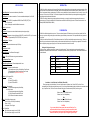
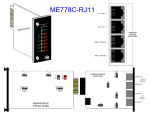
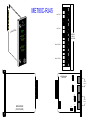
ME780C-RJ45
Line: RJ-45
Mini
Driver
Card
C-RJ45
ME780
Line: RJ-45
ODULE
MAIN M
Power
INTERFACE
MODULE
(REAR CARD)
-TD
Unit
A
-R D
-TD
Unit
B
Serial: 10-Pin RJ
-R D
Serial: 10-Pin RJ
JB2
INTERFACE MODULE
(REAR CARD)
1
2
3
MODEM A
Modem-toModem Line
JB4
1
2
3
MODEM B
JB6
MODEM A
1
2
3
MAIN MODULE
(FRONT CARD)
RS-232
Serial Line
JB7
JB5
1 2 3
1
2
3
MODEM B
SPECIFICATIONS:
Hardware Required: Cards can be installed only in MicroRacks.
Cable Required: For modem-to-modem line: Four-wire unconditioned twisted-pair, 19 to 26 AWG.
Interfaces: Serial: EIA/TIA-561 (compatible with EIA RS-232 and ITU-TSS [CCITT] V.24;
Line: Four-wire telco.
Internal: Card-edge for module--MicroRack interconnection.
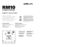
INTRODUCTION:
The Mini Driver Card is a dual rack card (it has a main [front] module and an interface [rear] module) incorporating two short-range modems. Pairs
of these Cards make communication between buildings safer, because custom-designed ferrite-core transformers give the Cards DC isolation. The
Mini Driver Card operates full duplex, at data rates up to 19,200 bps, over two twisted pairs. Maximum distances are up to 10 miles (16.1 km) at 1,200
bps and up to 2.5 miles (4 km) at 19,200 bps. The Card also incorporates Silicon Avalanche Diodes for protection against the damaging effects of
nearby lightning strikes and other harmful transients.
The Mini Driver Card is fabricated using the latest surface-mount technology, so you get high-quality short-range-modem performance on a
convenient rack card. The Card is available with RJ-45 line-interface connectors on its interface (rear) module. It fills one function-card slot in our
MicroRacks (RM202, RM204, RM208, or RM216).
Protocol: Asynchronous
CONFIGURATION:
Data Format: Transparent to numbers of data bits and stop bits and types of parity.
Flow Control: Transparent to all types of software (X-ON/X-OFF, robust X-ON/X-OFF, etc.) flow control;
DOES NOT support hardware (RTS/CTS, DTR/DSR, etc.) flow control.
Operating Mode: Full-Duplex.
Data Rates: Transparent to all data rates up to 19,200 bps
Transmit Level: 6 dBm.
Maximum Distance: See Distance Chart on page 5
Isolation: 1500 volts RMS minimum using custom transformers.
Surge-Response Time: 1psec.
Maximum Surge Protection: 600 watts dissipated after 1 msec.
User Controls: (5) Jumpers on interface module:
(2) Connect/disconnect Line A or B shield to/from Frame Ground;
(1) Connect/disconnect Signal Ground to/from Frame Ground;
(2) DSR tracks DTR (can not be set differently).
Indicators: (9) Front-panel LED's:
(1) Power;
(2) each for TD A and RD A
(2) each for TD B and RD B.
Connectors: On main module:
(1) 50-position card-edge male (to MicroRack);
On interface module:
(1) 50-position card-edge male (to MicroRack);
(2) 10-pin RJ female for modem-to-DTE lines;
(2) RJ-45 female for modem-to-modem lines.
Power: From MicroRack's power supply.
Input: 120 VAC or 240 VAC (user-selectable);
Output:: 10 VAC;
Consumption: 700 mW typical.
Fuse: On MicroRack:
400 mA when power supply is set to 120-VAC;
200 mA when power supply is set to 240-VAC.
The Mini Driver Card is designed to be easy to use. There are no internal jumpers or DIP switches to set on the main (front) module of the Card.
However, you may have to configure the jumpers on the interface (rear) module that you have selected. This chapter describes these jumpers and
how to set them.
The Mini Driver Interface Card has two RJ-45 line-interface ports and two 10-pin RJ-style serial-interface ports as shown on page 1. Before you
install the Card, you should examine the interface module you have selected and make sure that it is configured for your application. Each interface
module is configured by setting jumpers ("straps") on its circuit board, as described in the rest of this section.
Setting the Configuration Jumpers:
The figure on page 1, shows the locations of the jumpers on the interface module. These jumpers determine various grounding and signal
characteristics for the serial and modem-to-modem lines. The table below, provides a summary of jumper functions. The functions are described in
more detail afterward.
JUMPER
IN POSITIONS 1 AND 2
IN POSITIONS 2 AND 3
JB2
Line A Shield
No Shield*
JB2
Line B Shield
No Shield*
JB2
SGND tied to FGND
SGND not tied to FGND*
JB2
DSR A tracks DTR*
N/A
JB2
DSR B tracks DTR*
N/A
* factory-default settings
Line Interface: Line A Shield and Line B Shield (JB2 and JB4):
These jumpers apply to the line interface. When one of these jumpers is in positions 1 and 2, it links RJ-45 Pins 2 and 7 on the
corresponding line to the interface module's frame ground. (If you are using shielded twisted-pair cable, the shield can be connected to these
pins.) In positions 2 and 3, Pins 2 and 7 remain connected to each other, but are disconnected ("lifted") from frame ground.
JB2:
Positions 1 and 2 = Line A Shield Connected
Positions 2 and 3 = No Shield (default)
JB4:
Positions 1 and 2 = Line B Shield Connected
Positions 2 and 3 = No Shield (default)
CAUTION:
If you connect shield to frame ground, make sure that Pins 2 and 7, as
well as the cable shield, are connected to ground at one end of the cable
only. Connecting them at both ends of the cable will defeat the transformer
isolation and will leave your system open to damage from ground loops.
Serial Interface: Signal Ground and Frame Ground (JB5):
This jumper applies to the serial interface. In position 1 and 2, this jumper links the Signal Ground (SGND) line (Pin 5) of both serial lines to the interface module's frame ground (FGND). When this jumper is in positions 2 and 3, Pin 5 of both lines are
disconnected ("lifted") from frame ground.
JB5:
Positions 1 and 2 = SGND and FGND Connected
Positions 2 and 3 = SGND and FGND Not Connected (default)
DSR tracks DTR (JB6 and JB7):
These jumpers MUST be left in their default positions. Because the interface module is designed to work with a whole family of products, and not just the Async Line Driver Card, it is capable of supporting some functions that are not used by the Async
Line Driver Card. Some products in this family might require these jumpers to be set differently, but the Async Line Driver Card might malfunction if either of these jumpers is in the wrong position. Make sure the jumper is placed across Pins 1 and 2.
DO NOT place the jumper across Pins 2 and 3.
JB6 and JB7:
Positions 1 and 2 = DSR Tracks DTR (default)
Positions 2 and 3 = N/A
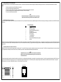
INSTALLATION:
This chapter describes the functions of the MicroRacks, tells how to install the front and rear modules of the Mini Driver Cards in them, and provides diagrams for wiring the interface connections correctly.
The MicroRacks: An Overview:
Mini Driver Cards are designed to be installed in our MicroRacks (product codes RM202 for 2-card models, RM204 for the 4-card models, RM208 for the 8-card models, and RM216 for the 16-card models). You will install Mini Driver Cards in any MicroRack the
same way. As an example of these products, the MicroRack 16, features sixteen slots for short-range modem cards, plus its own power supply. Measuring only 3.5" (8.9 cm) high, the MicroRack 16 is designed to occupy only 2U in a 19" rack. Sturdy front handles
allow the MicroRack 16 to be extracted and transported conveniently.
The MicroRack's Power Supply:
The power supply included with the MicroRacks uses the same mid-plane architecture as the line-driver cards. Slide the front module of the power supply into the MicroRack from the front, and slide the rear module in from the rear. The two modules plug into one
another in the middle of the rack. Secure the front module with thumbscrews and the rear module with conventional metal screws; these screws and thumbscrews come with the rack.
Switching the Power Supply On and Off:
The MicroRack's Power switch is located on the power supply's front panel. When the MicroRack is plugged in and switched on, the power supply will light the red LED on its front panel. Since the MicroRack is a "hot-swappable" rack, you don't have to
install any cards before switching on the power supply. Also, the power supply may be switched off at any time without harming the installed cards, and you can install or remove cards without turning off the power supply. However, you should always
unplug the power cord before removing, replacing, or switching the power supply or its fuses.
Replacing the Power Supply's Fuse:
The MicroRack's power supply uses a 400-mA fuse for 120-VAC circuits, and a 200-mA fuse 240-VAC circuits. The fuse compartment is located just below the AC socket on the power supply's rear module. To replace the fuse, follow these steps:
1. Making sure the rack is turned off and unplugged, use a small screw-driver to pop the compartment open: It will slide open like a drawer.
2. Notice that there are two fuses in the compartment: The rear fuse is "active", and the front fuse is the "spare".
3. If the active fuse appears to be blown, remove it from the clips and replace it with the spare from the front of the compartment. Note the size and rating of the blown fuse before discarding it.
4. Order a new replacement fuse. Both the 400-mA fuses (Littelfuse 239.400 or equivalent) and the 200-mA fuses (Littelfuse 239.200 or equivalent) measure 5 x 20 mm.
CAUTION:
For continued protection against the risk of fire, replace
blown fuses only with fuses of the same type and rating.
Switching the Power Supply Between 120 and 240 Volts:
Although the MicroRack is shipped from the factory with a customer-specified power-supply configuration, you may change the configuration yourself. Follow these steps to switch the configuration of the power supply between 120 VAC and 240 VAC.
1. Making sure the rack is turned off and unplugged, remove the power supply's front module and locate the two-position switch (labeled either "110/220" or "115/230") near the back of the card. Slide the switch to the setting
corresponding to your desired voltage.
2. Replace the existing fuses with fuses of the correct type.
3. If necessary, replace the power-supply cord with a country-specific cord. (For certain countries, your supplier might be able to give you a special quote on country-specific cords). Plug the cord back in.
Installing the Mini Driver Card in the MicroRack:
The Mini Driver Card is made up of a main (front) module and an interface (rear) module. The two cards meet inside the rack chassis; their mating 50-pin card-edge connectors plug into each other. Use these steps to install each Mini Driver Card into a
MicroRack:
1. Slide the rear module into the back of the MicroRack on the metal rails.
2. Secure the rear module using the included metal screws.
3. Slide the front module into the front of the chassis. It should meet the rear module when it is almost completely in the chassis.
4. Push the front module gently into the card-edge receptacle of the rear module. It should "click" into place.
5. Secure the front module using the thumbscrews.
NOTE:
Since the MicroRacks allow "hot swapping" of cards, it is not necessary
to power down the rack when you install or remove a Mini Driver Card.
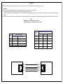
The RS-232 Serial Cables and Connectors:
The Mini Driver Card's RS-232 ports are always the lower two ports on its interface module. They are 10-pin female RJ-style connectors (compatible with regular male RJ-45 cable connectors), pinned according to a modified version of the EIA/TIA-561 standard,
as shown below.
Pin #:
1
2
3
4
5
6
7
8
9
10
The 10-Pin RJ Interface:
Signal Name/Description:
Not Used
DCE Ready (DCR [DSR])
Received Line Signal Detector (RLSD [CD])
DTE Ready (DTR)
Signal Common (SCOM [SGND])
Receive Data (RD)
Transmitted Data (TD)
Clear to Send (CTS)
Request to Send (RTS)/Ready for Receiving (RR)
Not Used
The Mini Driver Card is wired as a DCE (Data Communications Equipment) device. Therefore, it would normally be connected to DTE (Data Terminal Equipment) RS-232 devices. You might need to run a special cable or use a special modular adapter if either of the
RS-232 devices you want to attach have DB25 or DB9 serial-port connectors. Even if the DTE's serial ports are RJ-45 connectors, you might still need to use a specially pinned cable. Call Black Box Technical Support with these issues, or if you want to attach a DCE
device to the Card.
The Modem-to-Modem Line Cables and Connectors:
The Mini Driver Card's line ports are always the upper two ports on its interface module. They are 8-pin RJ-45 connectors, pinned for a standard telco-wiring environment, as shown below. The Mini Driver Card operates full duplex over four wires (two twisted
pairs). In all applications, the twisted-pair wire must be 26 AWG or thicker, unconditioned, dry, and metallic. Both shielded and unshielded cable yield favorable results.
NOTE:
The Mini Driver Card can only communicate in a closed data circuit with another
Mini Driver Card. It will not work with dialup analog circuits, such as those used
with standard modems.
The modem-to-modem cable connection must be specially cross-pinned, as shown below. If your cabling includes punchdown blocks, you can easily do the cross-pinning at a punchdown. If you will be running cable directly between two Mini Driver Cards, you
can get a custom cable from Black Box as a special quote, or you can use regular straight-through-pinned cable and repin one of the RJ connectors (that is, rearrange the wiring connections between the terminal block and the actual contacts). You might need
special crimping tools or new connectors; call Black Box for these items, or for technical support if you have difficulty.
12345678
Signal
N/C
GND
RCVXMT+
XMTRCV+
GND
N/C
Pin#
1
2
3
4
5
6
7
8
Pin#
8
7
5
6
3
4
2
1
Signal
N/C
GND
XMTRCV+
RCVXMT+
GND
N/C
RJ-45
OPERATION:
Once you have configured each Mini Driver Card and connected the cables, you are ready to operate the units. This chapter describes the Card's LED's and the power-up procedure.
Status LED's:
The Mini Driver Card features nine front-panel status LED's (shown on the first page) that indicate the condition of the modem and the communication link.
The Card will steadily light its green "PWR" LED as long as it is receiving power through its mid-plane MicroRack connection.
The green "TD" and "RD" LED's blink to show positive-state data activity. The red "TD" and "RD" LED's blink to show negative-state data activity. If the red "TD" and "RD" LED's are steadily lit, the modem-to-modem connection for that unit is idle.
Power-Up:
There is no power switch on the Mini Driver Card: Power is automatically applied to the Card whenever--and for as long as-- its card-edge connector is plugged into the MicroRack's mid-plane socket and the MicroRack's power supply is turned on.
NOTE:
The Mini Driver Card is a "hot-swappable" card--it will not be
damaged by plugging it in or removing it while the rack is powered up.
Data Rate
in (bps)
CABLE CHARACTERISTICS
MAXIMUM CABLE DISTANCES (mi)
19 AWG
22 AWG
24 AWG
19,200
2.5
2.1
1.3
16.3 ohm/1000 ft. (53.5 ohm/km)
9,600
3.7
2.3
1.7
83 nf/mi or 15.7 pf/ft.
32.6 ohm/1000 ft. (107 ohm/km)
4,800
4.9
4.9
2.5
83 nf/mi or 15.7 pf/ft.
51.65 ohm/1000 ft. (169.5 ohm/km)
2,400
8.2
5.8
4.6
1,200
10
8.3
6.8
WIRE
GAUGE
CAPACITANCE
RESISTANCE
19 AWG
83 nf/mi or 15.7 pf/ft.
22AWG
24 AWG
XMT+
XMTRCV+
RCV-
RCV+
RCVXMT+
XMT-