1
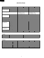
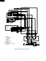
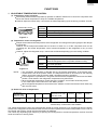
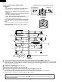
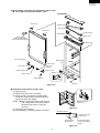
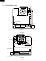
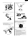
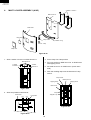
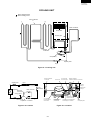
SJ-40J-GY/ BE
SJ-W40J-GY/ BE
SJ-36J-GY/ BE
SJ-W36J-GY/ BE
SERVICE MANUAL
SX885SE39JPZL
REFRIGERATOR-FREEZER
MODELS
SJ-40J
SJ-W40J
SJ-40J-GY/BE
SJ-36J-GY/BE
SJ-W40J-GY/BE
SJ-W36J-GY/BE
In the interests of user-safety (Required by safety regulations in some
countries) the set should be restored to its original condition and only
parts identical to those specified should be used.
DESTINATION ................ L
SJ-36J
SJ-W36J
Refrigerant; HFC-134a
Refer to "HFC-134a COOLING UNIT" Service Manual for handling this refrigerant.
TABLE OF CONTENTS
SPECIFICATIONS ......................................................................................................................................
DESIGNATION OF VARIOUS PARTS ........................................................................................................
LIST OF ELECTRICAL PARTS ...................................................................................................................
WIRING DIAGRAM .....................................................................................................................................
FUNCTIONS ...............................................................................................................................................
ASSEMBLING PROCEDURES OF MAIN PARTS AND CAUTIONS ..........................................................
COOLING UNIT ..........................................................................................................................................
REPLACEMENT PARTS LIST ....................................................................................................................
SHARP CORPORATION
1
page
2
3
4
5
7
14
21
22
SJ-40J-GY/ BE
SJ-W40J-GY/ BE
SJ-36J-GY/ BE
SJ-W36J-GY/ BE
SPECIFICATIONS
Items
Type
Outer dimensions
(Including spacer)
Height
Width
Depth
Rated storage volume
Defrosting
System
Start
Finish
Temperature control
No-frost freezer
Interior lamp
Evaporating pan
Refrigerator
R tray
Compartment
Fresh case
Vegetable case
Door pocket
Egg tray
Bottle pocket
Freezer
Ice cube maker
Compartment
Freezer case
Freezing case
Deodorizing system
R&L door / Dual Swing Door
COLOR
Items
Outside color
Inside color
SJ-40J
SJ-W40J
2-Door
1725mm(67.9")
590mm(23.2")
695mm(27.4")
368 liter(13.0 cu.ft)
F: 96 liter (3.4 cu.ft)
R: 272 liter(9.6 cu.ft)
Heater system
Automatic
Automatic
Automatic (Adjustable)
Yes
1
1
3
1
1
3
1
1
1
1
1
No
No
Yes
SJ-40J/ W40J/ 36J/ W36J-GY
Gray
White
RATING
Items
Rated voltage
Rated frequency
Climate class
Rated input of motors
Rated input of heaters
Refrigerant (Charging quantity)
Net Weight
(V)
(Hz)
(W)
(W)
(kg)
SJ-36J
SJ-W36J
2-Door
1585mm(62.4")
590mm(23.2")
695mm(27.4")
330 liter(11.7 cu.ft)
F: 96 liter(3.4 cu.ft)
R: 234 liter(8.3 cu.ft)
2
1
1
2
1
1
1
1
1
No
Yes
SJ-40J/ W40J/ 36J/ W36J -BE
Beige
White
SJ-40J
SJ-W40J
220-240
50
T
160-166
133-158
HFC-134a(110g)
66
69
2
SJ-36J
SJ-W36J
HFC-134a(110g)
62
65
SJ-40J-GY/ BE
SJ-W40J-GY/ BE
SJ-36J-GY/ BE
SJ-W36J-GY/ BE
DESIGNATION OF VARIOUS PARTS
The names in parenthesis are the denominations used in the Replacement Parts List.
SJ-36J / W36J
SJ-40J / W40J
9
9
11
10
1
2
3
4
5
11
1
10
10
2
3
4
5
12
6
10
12
6
10
17
7
17
7
13
14
15
8
8
16
17
Figure D-1. External Description
1. Light [Lamp]
Use a 10W lamp bulb with E12 base when replacing
the lamp bulb . Do use bulbs other than the specified
voltage(see affixed label by the bulb)
2. Refrigerator shelf [R tray]
3. Refrigerator temp. control knob
[R-temp. control knob]
4. Chilled case [Fresh case]
5. Lever [V-case shelf lever]
6. Fruit and vegetable crisper [Vegetable case]
7. Evaporating pan [Evaporating pan)
8. Adjustable feet [Adjustable leg ass’y]
9. Light switch [Door switch]
10. Free pocket [R door pocket]
11. Egg holder [Egg tray]
12. Bottle pocket [Bottle pocket]
13. Freezer temp. control knob[F-temp. dial ass’y]
14. Ice cube maker [Ice cube maker]
15. Stainless steel freezer case [Freezer case ass'y]
16. Freezer case [Freezing case]
17. Magnetic door seal [R-door packing/ F-door packing]
Mark: Cold air flow
Lamp
Door switch
Damper thermostat
Defrost timer
V-heater
F-thermostat
Fan motor
Defrost thermostat
Fuse ass'y
Def. heater ass'y
Compressor
Protector
Starting relay
Figure D-2. Constructions
3
SJ-40J-GY/ BE
SJ-W40J-GY/ BE
SJ-36J-GY/ BE
SJ-W36J-GY/ BE
LIST OF ELECTRICAL PARTS
ITEMS
R-door switch
F-Thermostat
Defrost heater
Damper thermostat
Defrost timer
TYPE NAME
PS 102-S
MM1-8109
—
MM1-6164
TMDF704FD2
RATING
125V-1A,250V-0.5A
125V-6A,250V-3A
220-240V
—
220-240V
50/ 60Hz
Lamp socket
Lamp
Defrost thermostat
Thermo. fuse
Fan motor
Compressor
—
—
US602S
—
3R00044B
GLY-70AA
250V 1A
240V 10W
125V 15A
250V 10A
220-240V/ 50Hz
220-240V/ 50Hz
Starting relay
Protector
V-heater
3003-7
4TM-308NFB-YY
A202
C-thermostat
US602S
—
—
220-240V 8000Ω
6.0-7.2W
250V 8A
SPECIFICATIONS
2 terminals type push-button
ON : -15˚C , OFF : -20˚C
378Ω
Open : Max -0.5˚C , Close : -5˚C
Integration type
Cycle time : 8h48m/7h20m(50/60Hz)
Delay time : 4m50s/4m2s(50/60Hz)
E-12
E-12
Open : 10˚C , Close : 1˚C
Cut off temperature : 70˚C or 72˚C
Main : 13.9 Ω (20˚C)
Aux : 17.9 Ω (20˚C )
14Ω
120˚C / 65˚C
*1
Open : 25˚C , Close : 17˚C
A018 / A133 / A043
*1 COIL POSITION OF COMP.
Common
Aux. coil
4
Main coil
SJ-40J-GY/ BE
SJ-W40J-GY/ BE
SJ-36J-GY/ BE
SJ-W36J-GY/ BE
WIRING DIAGRAM
Be sure to replace the electrical parts with specified ones for maintaining the safety and performance of the set.
G : GRAY
Br : BROWN(live)
YG : YELLOWISHGREEN
Y YELLOW
R : RED
P : PINK
B : BLUE(neutral)
Bk : BLACK
S-B : SKY-BLUE
G-Y : GREEN-YELLOW(earth)
W : WHITE
O : ORANGE
CONNECTED IN TERMINAL BOX
CONNECTOR
(O)
C-thermostat
V-heater
Defrost timer
F-thermostat
(BR)
(R)
(G)
TM
Lamp
Thermo.fuse
L
Terminal block
FM Fan motor
(O)
(S-B)
(BK)
(W)
E
Defrost heater
Source cord
(Y)
Door
switch
Defrost thermostat
(B)
Figure W-1. Wiring Diagram
5
Protector
Compressor
Starting relay
C
M
A
SJ-40J-GY/ BE
SJ-W40J-GY/ BE
SJ-36J-GY/ BE
SJ-W36J-GY/ BE
Cabinet ass'y
R-door switch
1
2
1
2
B-1
1
2
1
2
(S-B-1)
1
2
3
4
5
6
1
2
3
4
5
6
R-1
1
2
3
4
1
2
3
4
Multi-louver ass'y
Lamp
Socket ass'y
TM
Defrost timer
1 4 2 3
1 4 2 3
L
D timer
lead ass'y
RC box ass'y
V heater
S-B-1
Br-1
Bk-1
G-1
Y-1
Y-2
G-3
O-1
(R-1)
Br-2
Lead wire
FC-box ass'y
F-thermostat
C-partition ass'y
EV-cover ass'y
Lead wire
EV-cover ass'y
Fan motor
FM
Def. thermo. ass'y
Fuse ass'y
Def. heater ass'y
1
2
3
4
5
6
1
2
3
4
5
6
G-2
1
2
3
4
1
2
3
4
(W-1)
B-2
(Y-1)
B-3
(Bk-1)
W-1
(Y-2)
Terminal box
Blue
Brown
G : GRAY
Br : BROWN(live)
O : ORANGE
Y : YELLOW
R : RED
B : BLUE(neutral)
Bk : BLACK
S-B: SKY-BLUE
G-Y: GREEN-YELLOW(earth)
W : WHITE
Earth
Gray
Orange
C-thermostat
Protector
1
L
E
N
Source cord
Compressor
C
M
A
Starting relay
Terminal block
Figure W-2. Electric Accessories Layout
6
SJ-40J-GY/ BE
SJ-W40J-GY/ BE
SJ-36J-GY/ BE
SJ-W36J-GY/ BE
FUNCTIONS
1. ADJUSTABLE TEMPERATURE CONTROL
(1) Temperature control of freezer
Thermostat (senses freezer temperature) operates on ON/OFF switchover to control the compressor and
allows the freezer temperature to keep at a suitable temperature.
However adjust the freezer temp. control knob as follows depending upon the storing condition of foods.
FREEZER TEMP. CONTROL
MIN
MAX
5
4
2
3
KNOB
PURPOSE
SETTING
7(MAX)
For making ice rapidly or fast freezing.
4(MED)
For normal freezing.
1(MIN)
When frozen food or ice cream is not stored.
Figure F-1.
(2) Temperature control of refrigerator
Damper-thermostat senses temperature of the refrigerator and changes the opening angle of the damper
automatically.
However, as the Damper-thermostat has no function to switch on or off the compressor and cool air
circulating fan, the freezer temperature control causes temperature in the refrigerator to vary to some
extent.
However, adjust the refrigerator temp. control knob as follows depending upon the cooling condition.
MED
4
5
3
6
2
CHILLED
ZONE
MIN 1
7 Coldest
REFRIGERATOR
TEMP.CONTROL
KNOB
PURPOSE
SETTING
7(Coldest) For keeping foods fresher tasting.
When the refrigerator does not provide sufficient cooling.
4(MED)
For normal operation.
1(MIN)
When the refrigerator provides excessive cooling.
Figure F-2.
NOTE:
The refrigerator temperature is affected also by the freezer temperature. If the freezer temp.
control knob is set at the position "MAX", the temperature tends to be lower than the following
values, and if set at near the position "MIN", temperature tends to be higher.
If the refrigerator is operated for a long time with the freezer temperature control sets the "MAX"
position, foods stored in the refrigerator compartment may also freeze.
When refrigerator temperature control sets to the "Coldest", some foods stored may freeze.
In this case adjust control set back to the "MED" position.
When refrigerator temperature control sets to the "Coldest", some foods stored in fresh cases may
also become frozen.
(3) Reference value of temperature
SETTING OF
FREEZER TEMP.
CONTROL KNOB
7(MAX)
4(MED)
1(MIN)
SETTING OF
REFRIGERATOR TEMP.
CONTROL KNOB
Freezer
temperature
Approx.
-21˚C
Approx.
-18˚C
Approx.
-15˚C
Refrigerator
temperature
7(Coldest)
4(MED)
1(MIN)
Approx.
0˚c
Approx.
3˚c
Approx.
6˚c
The values shown above refer to the case where the
freezer temp. control knob is set at "MED".
The values shown above refer to the measurement carried out center area and 1/3 of overall height from the bottom
at each of the refrigerator and the freezer after machine has been operated at an ambient temperature of 30˚C with no
food stored and the door closed until the temperature is stabilized.
The values vary depending upon frequency of opening and closing the door, ambient temperature, amount of stored
foods and manner of storing foods.
7
SJ-40J-GY/ BE
SJ-W40J-GY/ BE
SJ-36J-GY/ BE
SJ-W36J-GY/ BE
The explanation of the operation manual
2. R & L DOOR / DUAL SWING DOOR
(1). Structure
Note
Do not destroy or damage the refrigerator body's
structure or internal structure intentionally.
Do not put any objects on the lower hinge or lower
hinge pin.
Please pay attention to the lower hinge pin and the
cam, do not let them get stuck.
Do not add oil to the refrigerator body, pulley, lower
hinge, since the plastic components will be
influenced by different kinds of oil.
Do not open the door of the refrigerator compartment
forcibly, the door may fall off or cause the personal
injury.
If the door can not be opened, please check the part
shown on the right figure to see if it is got stuck by
the foreign objects.
R&L structure of the
refrigerator body
R&L structure of
the door
Cam
(hinge projection)
(Positioned at the
four corners of the door)
Lower hinge pin
Lower hinge
Pulley
Figure F-3
Figure F-4
I
1
Hinge pin
L
2
Door cam projection A'
3
Door cam projection
Door cam
B
Door cam projection
2
Groove C
Groove D
Hinge
projection b
Door cam projection B'
approx. 2mm
3
A
3 -1
3 -2
Hinge projection
a
Hinge projection b'
Hinge projection a'
3 -3
3
means the part of the main body side.
3 -4
Door cam projection A'
Figure F-5
1
2
The hinge pins on both right and left sides are supported with the projection A A' of the door cam.
When the door is pulled, the hinge pin is guided to the groove C and the door is moved approx. 2 mm sideward.
When the hinge pin is engaged with the “J shaped” groove D of the projection A' of the door cam on the opposite
side, the door will be locked.
3 According to the opening degree of the door,
3 -1: Hinge pin and groove C
3 -2: Hinge projection b and door cam projection B
3 -3: Hinge projection b' on the opposite side and the projection A' of the door cam
3 -4: Hinge projection a' on the opposite side and the projection A' of the door cam
Any one of the above guides keeps the stage in which the door is moved approx. 2 mm sideward.
4 When the door is closed, the procedure of 1 thru 3 is reversed.
Even if the left and right doors are opened at the same time, both doors do not get off since the
width dimension between the projections A and A' of the door cam is small than that between the
left and right hinge pins.
8
SJ-40J-GY/ BE
SJ-W40J-GY/ BE
SJ-36J-GY/ BE
SJ-W36J-GY/ BE
(2) Disassembly, assembly and adjustment of R & L door
1 List of parts concerned with R & L door
Top hinge cover
Door cam tr
Special screw
Hinge cam tl
Door cam tl
Top hinge ass'y
Table support
Hinge cam tr
Silicon grease
(Before replacing door,
also prepare silicon grease.)
Special screw
Door cam support
Bottom hinge
ass'y
Body
Roller r ass'y
Door cam
support
Door cam bl
Door cam br
R-door stopper l
Hinge pin
Roller l ass'y
R-door stopper l
Hinge projection
Screw
Figure F-6
2Installation and removal of R & L door
(1) Open the door.
(2) Remove the door cam. (3 screws)
(3) Close the door, and open its opposite side.
In this time, hold the door with both hands to
prevent the door from falling.
NOTE
When replacing the door with the new
one, coat grease on the slide surface.
(Grease all door arms on the four
corners.)
(4) Pull off the door upward.
(5) For installation, reverse the above procedure.
The door cam tr is
shown here.
Figure F-7
Greasing surface
The door cam tr is
shown here.
All around the
side surface
Figure F-8
9
All around the side
surface, and bottom
surface
SJ-40J-GY/ BE
SJ-W40J-GY/ BE
SJ-36J-GY/ BE
SJ-W36J-GY/ BE
3Removal and installation of Bottom hinge ass'y and Top hinge ass'y
Remove the relevant screws.
NOTE
After replacement, adjust the position relationship of the door. (Refer to the next item.)
Proper climbing width of roller: 1 to 1.5 mm
Tolerance of climbing width of left and right rollers: within 0.5 mm
4
4Adjusting method of R&L door
If any heaviness is felt during opening/closing of the R&L door, any different weight is felt between leftward/
rightward openings, any large drop of the roller felt or any other abnormality is felt, adjust the following.
It must not be skipped or forgot to install any concerned part. Otherwise, it will cause the door to get off.
NOTE
CAUSE 1. The floor surface is not horizontal. Not level.
—> The refrigerator is twisted.
2. The climbing width of the roller of the R&L door is larger or smaller than specified. (Proper climbing
width: 1 to 1.5 mm)
Left side is
Right side is
(1) CAUSE 1; Adjust the adjustable legs as shown in
heavy.
heavy.
the right.(Figure F-9)
Project the right Project the left
adjustable leg.
If it can not be adjusted with the adjustable legs,
proceed with the following work.
adjustable leg.
Figure F-9
(2) CAUSE 2; Check the climbing width of the roller.Check the left and right rollers as a pair.
The service kit (CSOG-C803CBK0) is necessary.
Procedure outline (Cause 2)
(2) Check the climbing
width of the roller.
(1 to 1.5 mm as proper)
Smaller
Larger
(3) -1 Insert the spacer
into the roller assembly.
(3) -2 Insert the spacer
under the door cam.
(4) Check the door opening/closing.
(Opening/closing weight,
self-closing force, climbing
width of roller and left/right balance)
(5) Adjust the upper hinge.
(If the clearance on the hinge is
smaller, insert the spacer.)
R & L door
(The difference between the climbing widths of the
left and right rollers is 0.5 mm or less.)
1 ~ 1.5mm
(3)-1
The climbing width is smaller.
Insert the roller spacer between the roller
assembly and door.(Insert plural spacers
according to the climbing width.)
Lower hinge ass'y
Figure F-10
R & L door
(3)-2
The climbing width is larger.
Insert the door cam spacer between the door
cam bottom and door. (Insert plural spacers
according to the climbing width.)
[Note] • Don’t tighten any M3 flush screw strongly.
Otherwise, the screw will become idle.
Roller assembly
Roller spacer
(0.5 mm thick Left and
right as symmetric)
Figure F-11
R & L door
Door cam spacer
(Align the door to
0.5 mm thick corner R.)
Door cam bottom
Figure F-12
10
SJ-40J-GY/ BE
SJ-W40J-GY/ BE
SJ-36J-GY/ BE
SJ-W36J-GY/ BE
(4) Check the balance of the door opening force, selfclosing force and roller climbing width between the
left and right sides.
• Referring to the right figure, check the climbing
width.
R & L door
Door cam bottom
Lower hinge
ass'y
When the balance is poor between the left and right
sides, proceed with the following work.
0.5 to 1 mm
(both left and right sides)
Hinge pin
Figure F-13
(5) Adjust the upper hinge. (Because the position
relationship of the door and hinge varies at the upper
area of the door in Item (3)-1.)
Top hinge cover
Upper hinge
Table support
Swing the door
forward and backward
approx. 5 times.
12.5 ±1mm
Figure F-14
(a) Loosen the screws (6 pieces) on the hinge, and
swing the door forward and backward approx.
5 times. (Snugly fit the hinge to the door.)
Relocate the upper
hinge toward you.
Upper hinge
Lightly press here.
Table support
Figure F-15
(b) Lightly press the door, relocate the upper hinge
toward you, and tighten the screw.
Determine the position
with the screws.
Figure F-16
• Check the clearance between the upper hinge
and Door cam upper. If it is rubbed during opening/
closing, insert the spacer (T hinge SPA05) under
the table support.)
(Insert plural spacers according to the adjustment
width.)
Upper hinge
Upper hinge
T hinge SPA05
(0.5 mm thick on the
left and right sides
as symmetric)
2 mm or less
Door cam upper
R & L door
Table support
Figure F-17
Figure F-18
[Details of service parts]
1. Spacer assembly
* 1 Part code:
CSOG-C803CBK0
Components: Roller spacer
2. Silicon oil
* 2 Part code:
Door cam spacer
FPAK-A275CBE0
11
T hinge SPA05
Two pieces per each pack.
(They are all 0.5 mm thick.)
SJ-40J-GY/ BE
SJ-W40J-GY/ BE
SJ-36J-GY/ BE
SJ-W36J-GY/ BE
3. DEFROSTING
(2) Where is melted ice brought
(1) No defrosting operation is necessary
1. Melted ice is brought into the evaporating pan
No defrosting operation is necessary.
at the back of the set and is evaporated here
As this machine is so designed that a built-in
by the heat of compressor.
evaporator cools air and a fan circulates cooled
2. Be sure that the evaporating pan is inserted
air, neither the freezer nor the refrigerator is
correctly and is level.
frosted, though the evaporator is frosted.
The frosted evaporator is defrosted automatically
due to the function of defrosting timer and heater,
requiring no defrosting operation.
(3) The following circuit diagrams in the table show automatic defrosting function of the refrigerator with
timer and defrost thermostat.
Electric diagram
Defrost thermostat ON
Timer contact
Thermo. fuse
Defrost heater
TM
Defrost
thermostat (ON)
COMP
Compressor
SOURCE
F-thermostat
Compressor running
Timer motor running
Timer motor
Operation
1. Cooling
(Normal)
Description
The integration timer integrates running
time of the compressor.
When it reaches cycle time of defrost
timer, the timer contact is changed to
start defrosting.
Figure F-19
Defrost thermostat ON
Compressor stops
Timer motor stops
Timer contact
Thermo. fuse
Defrost heater
TM
Defrost
thermostat (ON)
COMP
Compressor
SOURCE
F-thermostat
Timer motor
2. Defrosting
(Time 20 to 30 min.)
The timer contact is changed to start
defrosting, the timer motor stops and
power is supplied to the defrost heater.
It takes about 20 to 30 min. to defrost.
When little frosted, the defrosting take
little time. When much frosted, the defrosting takes much time.
Figure F-20
Defrost thermostat OFF
SOURCE
F-thermostat
Compressor stops
Timer motor running
Timer contact
Thermo. fuse
Defrost heater
TM
Defrost
thermostat (OFF)
COMP
Compressor
(Time approx. 5 min.)
Timer motor
3. Drain
When the defrost thermostat becomes
OFF, the timer motor starts running.
During the operation time
(delay time of defrost timer)
defrosted water drained outside the
refrigerator.
Figure F-21
Defrost thermostat OFF
Timer contact
Thermo. fuse
Defrost heater
Defrost
thermostat (OFF)
TM
Figure F-22
12
COMP
Compressor
SOURCE
F-thermostat
Compressor running
Timer motor stops
Timer motor
4.Restart
Timer contact is changed to cooling
operation and the compressor starts
running and the timer motor stops.
Defrost thermostat contact becomes
ON when it's cooled. And the timer
motor starts running(Figure F-19)
SJ-40J-GY/ BE
SJ-W40J-GY/ BE
SJ-36J-GY/ BE
SJ-W36J-GY/ BE
(4) As a reference to determine the causes of trouble, malfunction and phenomena are described below.
Refer to the following when repairing.
1. Disconnection of defrost heater
As off-cycle defrosting is performed, the defrosting time is extremely prolonged. Each time defrosting is
started, the freezer temperature rises and a portion of ice and stored foods are melted.
2. Melted thermo. fuse or opened-circuit due to the defect of defrost thermostat.
When the above mentioned trouble occurs in cooling operation, the timer motor does not run, defrosting
will not take place, and consequently freezing is caused. In the above mentioned condition, when the timer
shaft is turned by hand to defrost, the timer motor runs during the operation time. However, the motor stops
from the time when the contact is changed, and freezing causes.
NOTE:
As the thermo. fuse assembly is intended to prevent dangers, do not use it under shorted condition even
for a short period.
4. DEW PREVENTION
The hot pipe, namely D.P.-condenser, is arranged around the flange part of
cabinet and the C-partition plate, preventing dew from being generated on
the cabinet.
NOTE:
D.P.-condenser pipe may be felt hot if touched by hand while the
compressor is in operation.
If you are asked about this, please explain that the hot pipe serve to
prevent the dew generation.
Hot pipe
Figure F-23
5. INSPECTION OF INITIAL STARTING
(1) Inspection of cooling unit
1. Set the temperature control knob to "MAX" and check that the compressor starts to operate.
2. Depress the door switch to run the fan and check that cool air is blown out of the cold air outlet of the
freezer and the refrigerator.
3. When the compressor does not work, check that the timer is not set to "defrost" position.
4 It takes about an hour and a half or two hours to put food in the refrigerator after starting operation.
NOTE:
After return the temperature control knob to "MED" position.
When the refrigerator is operated initially after installed, the compressor may vibrate excessively for 1 to 2
min. However, vibration becomes normal if it is continuously operated.
(2) Inspection of defrost device
Operate the refrigerator for 20 to 30 min. and then check the defrost device in the following procedures:
Allow 5 min.to restart the compressor since immediate starting after stopping will cause unsmooth operation.
1. Turn the timer shaft clockwise with a screw driver.
At this time, make certains the timer clinks and the compressor stops.
2. After more than 5 min., turn the shaft further to operate.
Make certain cooling operation is started again.
13
SJ-40J-GY/ BE
SJ-W40J-GY/ BE
SJ-36J-GY/ BE
SJ-W36J-GY/ BE
ASSEMBLING PROCEDURES OF MAIN PARTS AND CAUTIONS
1.C-INSULATION ASSEMBLY(A340)
Corner sealer l
V-heater
C-partition r
F-thermo.capi. tube
Drain sealer a
F-thermostat
Center insulation a
A sealer rf b
W-sealer fr a
C-partition f
Lead wire f-box
Corner sealer r
W-sealer rf-c
A-sealer ag5
A sealer rf c
Figure A-1
1. Stick A-sealer rf c on outside of C-partition f.
C-partition f
A sealer rf c
Figure A-2
2. Insert F-thermo capi. tube into capillary pipe of
F- thermostat.
more than 5mm
3. Connect terminals of Lead wire f box to F-thermostat
as shown.
F-thermo capi. tube
F-thermostat
Lead wire f box
(RED)
24mm
(BROWN)
95mm
78.5mm
149mm
50.5mm
F-thermostat
Figure A-3
14
SJ-40J-GY/ BE
SJ-W40J-GY/ BE
SJ-36J-GY/ BE
SJ-W36J-GY/ BE
4. Form capillary tube of F-thermostat as shown
Figure A-3, hook each side the claw of C-partition f.
(Figure A-4)
Corner sealer r
Corner sealer l
5. Form the end of capillary tube of F-thermostat and fix
with claw as shown. (Figure A-4 or Figure A-5)
A sealer rf c
Tapping screw
C-partition f
B
F-thermostat
Figure A-4
6. Stick W-sealer rf c . (Figure A-5 )
F-thermo capi. tube
Lead wire
f box
W-sealer
rf c
Figure A-5
5mm
7. Stick V-heater on Center insulation a.
Stick A sealer rf b on Center insulation a.
(Figure A-6)
Paper tape
V heater
Center insulation a
A sealer rf b
Figure A-6
8. Set Center insulation a on C-partition f. (Figure A-7 )
C partition f
A sealer rf b
9. Wiring Lead wire f box on Center insulation a.
A sealer rf c
Center
insulation a
10. Set the “8” ass’y on C-partition r and fix with claws.
Fix by tapping screw.
W sealer fr a
11. Stick W-sealer fr a and Drain sealer a and Corner
sealer R&L on outside of “10” ass’y.
(Figure A-4,A-7 )
SEC. B
Figure A-7
15
C -patition r
SJ-40J-GY/ BE
SJ-W40J-GY/ BE
SJ-36J-GY/ BE
SJ-W36J-GY/ BE
2.RC-BOX COV. ASSEMBLY (A195)
Thermo. cap.sealer
Dial sealer
Defrost timer
Damper thermostat
A sealer ag 2
A sealer ag 3
R control label
A sealer ag 4
R-air guider
R-temp. control knob
A-sealer ag 1
R-c box cover
D timer lead ass'y
Figure A-8
1. Stick sealers as show figure.
A-sealer ag 3
A-sealer ag 3
A-sealer ag 1
A-sealer ag 1
A-sealer ag 1
A-sealer ag 1
Dial sealer
A-sealer ag 2
A-sealer ag 4
A-sealer ag 1
Overlap
Over 10mm
Figure A-9
16
SJ-40J-GY/ BE
SJ-W40J-GY/ BE
SJ-36J-GY/ BE
SJ-W36J-GY/ BE
Defrost timer
2. Connect D timer lead ass’y to defrost timer.
D timer lead ass'y
Figure A-10
3. Fix defrost timer on R-c box cover with tapping screw.
R-c box
cover
Defrost timer
Tapping screw
Figure A-11
4. Fasten damper thermostat on foodliner with 2 tapping
screws.
Tapping screw
Tapping screw
Figure A-12
5. Fix “1” ass’y on “4” ass’y.
Figure A-13
6. Fasten R-c box cover on “5” ass’y with 3 tapping
screws.
Tapping screw
Tapping screw
Figure A-14
17
Tapping screw
SJ-40J-GY/ BE
SJ-W40J-GY/ BE
SJ-36J-GY/ BE
SJ-W36J-GY/ BE
3. E.V. COVER ASSEMBLY (A800)
E. v.cover
B
B
E.v.cover sealer d
Fuse ass'y
Figure A-15
E.v.cover sealer c
Tapping screw
Fan motor ass'y
L band c
E.v. cover
sealer b
L band c
Defrost thermo ass'y
Don't loosen
Set metal side below
Al Tape
E.v cover insulation
E.v.cover sealer a
Fuse ass'y
E.v.water sealer
E.v.cover al sheet
Figure A-16
18
SJ-40J-GY/ BE
SJ-W40J-GY/ BE
SJ-36J-GY/ BE
SJ-W36J-GY/ BE
1. Stick U sealer handle to Fan motor holder a.
C
Fan motor holder a
4. Set Fan clamp to Propeller fan and insert it to the
shaft of Fan motor.
Propeller fan 100
Fan clamp
_
7+2mm
Motor
cushion
Fan clamp
Motor cushion
Fan boss
SEC. C-C
C
right
wrong
Figure A-17
Figure A-20
2. Insert the terminals of Lead e.v. cover ass’y to Fan
motor.
5. Fix L band c.
Installation of L band c
Not come out of claw
10±5mm
Fan motor
SEC. B-B
Cut of top
Lead e.v cover ass'y
Not come out of claw
White
Gray
Figure A-21
Figure A-18
The terminals No. 1, 2 and 4 are completely inserted as
an assembly unit of Lead ev cover assembly.
When assembling the assembly, insert the Def. thermo.
(blue) No. 3 and Thermo. fuse (black) No. 5.
3. Insert shaft of Fan motor to the hole of Motor cushion.
Set at Fan motor holder a.
Next, insert the boss of rear to the hole of Motor
cushion, set at Fan motor holder b.
Then, fix with Tapping screw (2pieces).
Fan motor holder b
Fan motor(Blue)
Def. thermo.(Pink)
Fan motor(Gray)
Tapping
Fan motor
Def. thermo. (Blue)
Motor cushion
Fan motor holder a
Figure A-19
1
2
3
4
5
6
Thermo. fuse(Black)
Thermo. fuse(White)
Figure A-22
Cautions
1. Don’t mistake the insertion direction and position of
the terminal of each lead wire. If it is mistaken,
cooling may be defective.
2. Securely fasten each lead wire.
3. After assembly, verify that the fan motor runs normally.
Otherwise, lead wire may be sometimes in contact
with the end surface of metal and propeller fan.
4. Don’t store any part at the area exposed to the direct
sunlight or high temperature. (Because the fuse
assembly is molten at 70°C.)
5. To prevent an electrical part from being rusted, don’t
moisten it with water.
19
SJ-40J-GY/ BE
SJ-W40J-GY/ BE
SJ-36J-GY/ BE
SJ-W36J-GY/ BE
4.
MULTI LOUVER ASSEMBLY (A165)
A-sealer m-louver a
Multi louver ins.
Multi louver
Lamp label
Lamp socket
W sealer r-air-g
Lamp
Lamp cover
Figure A-23
1. Stick A sealer m-louver a on Multi louver ins.
Multi louver ins.
A sealer
M-louver A
A sealer
M-louver A
3. Screw Lamp into Lamp socket.
4. Fix Lamp socket on Multi louver ins. on Multi louver
with tapping screw.
5. Set multi louver ins. on Multi louver. (match each
hole)
6. Stick the masking tape over the harness of Lamp
socket.
>PS<
Lamp socket
Multi louver ins.
Tapping screw
Tapping screw
Multi louver
Figure A-24
2. Stick Lamp label on Multi louver.
Lamp
Multi louver
Tape(24 x 50)
Lamp label
>PS<
19mm
3mm
4mm
19mm
Figure A-26
Figure A-25
20
SJ-40J-GY/ BE
SJ-W40J-GY/ BE
SJ-36J-GY/ BE
SJ-W36J-GY/ BE
COOLING UNIT
Mark: Refrigerant flow
Mark: Brazing portion
Inner condenser
C
L
R
Back condenser
Evaporator
Suction pipe
Bottom
condenser
Compressor
Capillary tube
Dryer
Figure C-1. Cooling unit
Bottom condenser
to Hot pipe
Capillary tube
Pinch Point
S.P connector
to Suction pipe
Bottom condenser
to Back condenser Pinch Point
Dryer
Hot pipe
to Dryer
Charge pipe
Inner
condenser
Evaporator
Discharge
P connector
Charge pipe
to Dryer
Back condenser
Charge pipe L
Suction pipe S.P.
Bottom
connector
condenser
Compressor
Discharge P. connector
to Back condenser
S.P connector
to Compressor's
suction tube
Figure C-2. Location
Charge pipe
to Compressor's
process tube
Compressor's discharge pipe
to Discharge P. connector
Figure C-3. Location
21
Dryer
to Capillary tube
SJ-40J-GY/ BE
SJ-W40J-GY/ BE
SJ-36J-GY/ BE
SJ-W36J-GY/ BE
REPLACEMENT PARTS LIST (SJ-W40J / W36J)
REF. NO.
PART NO.
DESCRIPTION
Q'TY
CODE
SJ-W40J SJ-W40J SJ-W36J SJ-W36J
-GY
-BE
-GY
-BE
ELECTRIC PARTS
1-51
1-81
1-82
1-83
1-84
1-85
1-86
1-87
1-88
1-89
1-140
1-141
1-142
1-143
1-144
1-145
1-146
1-148
QSW-PA082CBEA
FW-VZA137CBE0
QSWTDA024CBE0
QSOCAA065CBE0
RLMP-A012CBE0
FHETBA126CBE0
FW-VZA138CBE0
RTHM-A088CBE0
QACC-A097CBE0
RHETBA202CBE0
RMOTRA040CBE0
FFS-TA048CBK0
FTHM-A024CBK0
FW-VZA136CBE0
RSTT-A144CBE0
FCNW-A558CBK0
FTHM-A020CBK0
RHOG-A131CBE0
Door switch
D timer lead ass’y
Defrost timer
Lamp socket
Lamp
Def.heater ass’y
Lead wire f-box
F-thermostat
Source cord
V-heater
Fan motor
Fuse ass’y
Defrost thermo.ass’y
Lead ev-cover ass’y
Starting relay
Relay wire ass’y
C-thermo. ass'y
Protector
2-1
2-1
2-2
2-2-1
2-3
2-4
2-5
2-21
2-22
2-22
2-23
2-23
2-24
2-24
2-28
2-28
2-29
2-29
2-30
2-30
2-51
2-52
2-53
2-54
2-55
2-56
2-57
2-58
2-59
2-60
2-61
2-62
2-63
2-64
2-65
2-66
2-67
2-68
2-69
2-70
2-71
2-72
2-73
2-74
2-75
2-81
2-82
2-84
2-85
2-85
2-86
2-86
2-87
FCABCA527CBK0
FCABCA528CBK0
FLEGPA067CBK0
FAJS-A013CBK0
FLEGPA068CBK0
PBOX-A071CBFA
PCOVPA164CBFA
FHNG-A135CBY0
MSLI-A036CBFA
MSLI-A036CBFB
MSLI-A037CBFA
MSLI-A037CBFB
DHNG-A313CBY0
DHNG-A315CBY0
GCOV-A176CBFA
GCOV-A176CBFB
LPLTPA206CBFA
LPLTPA206CBFB
PCAP-A006CBFX
PCAP-A006CBFY
PGID-A150CBF0
PSEL-A552CBE0
PSEL-B641CBE0
PSEL-B642CBE0
PSEL-B643CBE0
FPACGA282CBEA
LHLD-A501CBEA
HGRL-A171CBFA
PFPFPB145CBE0
PSEL-B648CBE0
MLOV-A016CBFA
PFPFPB141CBF0
PGID-A151CBFA
FKNB-A032CBY0
LBND-A018CBE0
LBND-A023CBE0
LHLD-A488CBFA
LHLD-A489CBFA
LPLTMA399CBP0
LRAL-A035CBFA
LRAL-A036CBFA
NKOM-A022CBE0
PCAP-A063CBE0
JKNB-A049CBFA
PSEL-B644CBE0
GCOVPA104CBFA
PDMP-A042CBE0
PSEL-B244CBE0
HGRL-A170CBFA
HGRL-A172CBFA
PFPFPB144CBF0
PFPFPB149CBF0
TLAB-A786CBR0
Center plate rf assy
Center plate rf assy
Leg holder l ass’y
Adjustable leg ass’y
Leg holder r ass’y
Terminal box
Terminal cover
Top hinge ass’y
Hinge cam tl
Hinge cam tl
Hinge cam tr
Hinge cam tr
Bottom hinge s ass'y
Bottom hinge s ass'y
Top hinge cover
Top hinge cover
Table support
Table support
Screw cover
Screw cover
R-air guider
Dial sealer
A-sealer ag1
A-sealer ag2
A-sealer ag3
F-sub. packing
Clip
Shower duct
Shower duct ins.
A-sealer shower duct
Fan louver
F duct insu.
F air guider
F temp. dial ass’y
Fastening band a
L-band c
Ev.pan holder
E.v. holder
Dryer support
Fresh rail l
Fresh rail r
V-roller cab
Drain cap
R-temp. control knob
A-sealer ag4
R-cbox cover
Damper thermostat
Thermo. cap. sealer
Multi louver
Multi louver
Multi louver ins.
Multi louver ins.
R control label e
1
1
1
1
1
1
1
1
1
1
1
1
1
1
1
1
1
1
1
1
1
1
1
1
1
1
1
1
1
1
1
1
1
1
1
1
1
1
1
1
1
1
1
1
1
1
1
1
1
1
1
1
1
1
1
1
1
1
1
1
1
1
1
1
1
1
1
1
1
1
1
1
AK
AM
AY
AP
AH
AZ
AK
AY
AV
AS
AZ
AP
AP
AK
AW
AM
AP
AT
1
1
2
1
1
1
1
1
1
1
1
1
3
1
1
2
1
1
1
3
1
1
2
1
1
1
1
1
2
1
2
1
1
1
2
1
1
1
1
1
2
1
1
1
1
1
2
1
1
1
1
1
1
1
1
1
3
1
1
2
1
1
1
3
1
1
2
1
1
1
1
1
2
1
2
1
1
1
2
1
1
1
1
1
2
1
1
1
1
1
2
1
1
1
1
1
1
1
1
1
3
1
1
2
1
1
1
3
1
1
2
1
1
1
1
1
2
1
2
1
1
1
2
1
1
1
1
1
2
1
1
1
1
1
2
1
1
1
1
1
1
1
1
1
3
1
1
2
1
1
1
3
1
1
2
1
1
1
1
1
2
1
2
1
1
1
2
1
1
1
1
1
2
1
1
1
AK
AL
AM
AE
AM
AE
AE
AK
AD
AD
AD
AD
BB
BB
AP
AN
AP
AP
AB
AC
AG
AC
AC
AB
AB
AE
AC
AQ
AG
AC
AN
AB
AN
AK
AP
AC
AD
AD
AD
AF
AF
AG
AE
AD
AB
AP
AZ
AB
AM
AL
AG
AE
AE
MECHANICAL PARTS
22
SJ-40J-GY/ BE
SJ-W40J-GY/ BE
SJ-36J-GY/ BE
SJ-W36J-GY/ BE
REF. NO.
PART NO.
DESCRIPTION
Q'TY
CODE
SJ-W40J SJ-W40J SJ-W36J SJ-W36J
-GY
-BE
-GY
-BE
2-88
2-88
2-89
2-90
2-91
2-92
2-93
2-94
2-95
2-96
2-97
2-98
2-100
2-101
2-103
2-104
2-105
2-106
2-107
2-111
2-112
2-140
2-141
2-142
2-143
2-144
2-145
2-146
2-147
2-148
2-149
2-150
2-151
2-152
2-153
2-154
PSEL-B647CBE0
PSEL-B664CBE0
LPLTMA536CBP0
PSHEMA174CBP0
PFPFPB146CBF0
PSEL-B650CBE0
PSEL-B651CBE0
PSEL-B652CBE0
PSEL-B670CBE0
PSKR-A217CBFA
PSKR-A218CBFA
PTUBBA069CBE0
PBOX-A113CBRA
PCOVAA013CBEH
PSEL-B756CBE0
PSEL-B645CBE0
PSEL-B751CBE0
PSEL-B752CBE0
PSEL-B753CBE0
GCOV-A177CBFA
USRA-A228CBFA
LCRA-A010CBE0
LHLD-A389CBF0
LHLD-A484CBFA
LHLD-A485CBFA
NFANPA011CBF0
PSEL-B209CBE0
GCOV-A178CBF0
LBND-A023CBE0
PSEL-B637CBE0
PSEL-B638CBE0
PSEL-B639CBE0
PSEL-B640CBE0
PSHEMA173CBE0
PSEL-B740CBE0
PSEL-B755CBE0
A-sealer m-louver a
A-sealer m-louver a
Drip tray
Heater cover
Center insulation a
W-sealer fr a
A-sealer rf b
Drain sealer a
W-sealer rf-c
C-partition r
C-partition f
F-thermo. capi. tube
F-control box slk
Charge hole cover
W-sealer r-air-g
A-sealer ag5
A-sealer rf c
Corner sealer r
Corner sealer l
Lamp cover
Evaporating pan
Fan clamp
Motor cushion
Fan motor holder b
Fan motor holder a
Propeller fan 100
U-sealer handle
E.v cover
L-band c
E.v cover sealer a
E.v cover sealer b
E.v cover sealer c
E.v cover sealer d
Ev cover al sheet
Ev-cover insulation
E.v water sealer
2
1
1
1
2
4
1
2
1
1
1
1
1
1
1
2
1
1
1
1
1
2
1
1
1
2
1
2
1
1
1
1
1
1
1
2
1
1
1
2
4
1
2
1
1
1
1
1
1
1
2
1
1
1
1
1
2
1
1
1
2
1
2
1
1
1
1
1
1
1
2
1
1
1
2
4
1
2
1
1
1
1
1
1
1
2
1
1
1
1
1
2
1
1
1
2
1
2
1
1
1
1
1
1
1
2
1
1
1
2
4
1
2
1
1
1
1
1
1
1
2
1
1
1
1
1
2
1
1
1
2
1
2
1
1
1
1
1
1
1
AC
AC
AM
AL
AT
AD
AC
AD
AB
AX
AX
AD
AS
AH
AB
AC
AB
AC
AB
AG
AN
AD
AF
AH
AH
AD
AB
AS
AC
AD
AB
AB
AC
AH
AE
AE
1
1
1
1
1
1
1
1
2
1
1
1
1
1
2
2
2
1
1
1
1
1
1
1
1
1
1
1
1
1
2
1
1
1
1
1
2
2
2
1
1
1
1
1
1
1
1
1
1
1
1
1
2
1
1
1
1
1
2
2
2
1
1
1
1
1
1
1
1
1
1
1
1
1
2
1
1
1
1
1
2
2
2
1
1
1
1
1
BB
BP
BP
AU
BV
BV
BR
BT
AE
AE
AE
AE
AL
AK
AL
AK
AS
AM
AD
AM
AD
AE
AE
AE
AE
AY
AX
AM
AK
AK
AK
AZ
AK
AM
AM
AD
AF
AL
DOOR PARTS
3-21
3-22
3-22
3-23
3-26
3-26
3-26
3-26
3-26-1
3-26-1
3-26-2
3-26-2
3-26-3
3-26-3
3-26-4
3-26-4
3-26-5
3-26-6
3-26-6
3-26-7
3-26-7
3-26-8
3-26-8
3-26-9
3-26-9
3-27
3-27
3-28
3-28
3-29
3-29
3-30
3-31
3-32
3-32
3-33
*1
*2
DFRM-A079CBK0
FDORFB094CBK0
FDORFB095CBK0
FPACGA281CBK0
FDORRA940CBK0
FDORRA941CBK0
FDORRA943CBK0
FDORRA946CBK0
MSLI-A032CBFA
MSLI-A032CBFB
MSLI-A033CBFA
MSLI-A033CBFB
FHLD-A066CBK0
FHLD-A068CBK0
FHLD-A067CBK0
FHLD-A069CBK0
LPLTMA534CBW0
LSTPPA100CBFA
LSTPPA100CBFB
LSTPPA101CBFA
LSTPPA101CBFB
MSLI-A034CBFA
MSLI-A034CBFB
MSLI-A035CBFA
MSLI-A035CBFB
FPACGA283CBK0
FPACGA284CBK0
HDECQA369CBRA
HDECQA369CBRB
JHNDPA106CBFA
JHNDPA106CBFB
LPLTMA531CBP0
GDAI-A049CBM0
HBDGDA812CBEA
HBDGDA812CBEB
PKYU-A118CBE0
CSOG-C803CBK0
FPAK-A275CBE0
F-frame ass’y
F-door ass’y
F-door ass’y
F-door packing
R-door ass’y
R-door ass’y
R-door ass’y
R-door ass’y
Door cam tl
Door cam tl
Door cam tr
Door cam tr
Roller l ass’y
Roller l ass’y
Roller r ass’y
Roller r ass’y
Door cam support
R-door stopper l
R-door stopper l
R-door stopper r
R-door stopper r
Door cam bl
Door cam bl
Door cam br
Door cam br
R-door packing
R-door packing
R-handle trim
R-handle trim
R-door handle
R-door handle
Handle support
Badge base
Badge
Badge
Badge tape
Spacer assembly [320-DP-TK]
Silicon oil [S. oil pack (ks64f)]
23
SJ-40J-GY/ BE
SJ-W40J-GY/ BE
SJ-36J-GY/ BE
SJ-W36J-GY/ BE
REF. NO.
PART NO.
DESCRIPTION
Q'TY
CODE
SJ-W40J SJ-W40J SJ-W36J SJ-W36J
-GY
-BE
-GY
-BE
OTHER PARTS
4-21
4-22
4-23
4-24
4-140
4-141
4-142
LX-TZA046CBE0
LX-TZ0127CBE0
LX-TZA042CBE0
LX-DZ0133CBE0
LX-BZA018CBE0
QTAN-A013CBE0
QTAN-A012CBE0
Special screw
Special screw
Special screw
Special screw
Special screw
Solderless term. a
Solderless term. b
8
4
4
6
1
3
1
8
4
4
6
1
3
1
8
4
4
6
1
3
1
8
4
4
6
1
3
1
AC
AA
AB
AA
AA
AH
AH
1
1
1
1
1
1
1
1
1
3
3
1
1
1
1
1
2
1
1
1
1
1
1
1
1
1
3
3
1
1
1
1
1
2
1
1
1
1
1
1
1
1
1
2
2
1
1
1
1
1
2
1
1
1
1
1
1
1
1
1
2
2
1
1
1
1
1
2
AU
AC
AC
AR
BD
AY
AX
AL
AN
AM
AT
AS
AH
AU
AV
AZ
AB
1
1
1
1
1
1
4
4
1
4
4
4
1
1
1
1
1
1
1
1
1
1
4
4
1
4
4
4
1
1
1
1
1
1
1
1
1
1
4
4
1
4
4
4
1
1
1
1
1
1
1
1
1
1
4
4
1
4
4
4
1
1
1
1
AX
AG
AG
AE
BT
AH
AD
AF
AZ
AC
AA
AA
BC
AD
AG
AF
1
1
1
1
1
1
4
1
1
1
1
1
1
1
1
1
4
1
1
1
1
1
1
1
1
1
4
1
1
1
1
1
1
1
1
1
4
1
1
1
AQ
AQ
AL
AX
AH
AK
AD
AD
AD
BF
BE
AG
ATTACHMENT PARTS
5-111
5-112
5-113
5-114
5-115
5-115-1
5-115-2
5-116
5-117
5-118
5-119
5-120
5-121
5-122
5-123
5-124
5-125
FSRA-A146CBY0
MLEVPA005CBFA
MLOV-A017CBFA
UTNA-A281CBFA
FYOK-A130CBK0
UYOK-A291CBW0
UYOK-A292CBFA
GDORPA064CBFA
UPOK-A149CBFA
UPOK-A150CBFA
USRA-A229CBFA
UTNA-A280CBFA
UTNA-A282CBFA
UYOK-A288CBFA
UYOK-A289CBFA
UYOK-A290CBFA
PCUS-A005CBE0
Ice cube maker
V-case shelf lever
V-case shelf louver
V case shelf
Freezer case ass’y
Sus case
Freezing case frame
Fresh door
Bottle pocket
R door pocket
R tray
F case shelf
Egg tray
Fresh case
Vegetable case
Freezing case
Fresh door cushion
6-51
6-52
6-53
6-140
6-141
6-142
6-143
6-144
6-146
6-147
6-148
6-149
6-151
6-152
6-153
6-154
FDRY-A006CBK0
PKYU-A034CBE0
PKYU-A035CBE0
PCLI-A047CBE0
PCMPLA177CBE0
PCOVPA235CBE0
PSPAFA033CBE0
PSPAGA041CBE0
FFRM-A109CBK0
LX-BZA071CBM0
LX-NZ0078CBM0
LX-WZA003CBE0
PPIPCA222CBE0
PPIPCA252CBE0
PPIPCA338CBE0
PPIPCA339CBE0
Dryer ass’y
Sp-butyl f
Sp-butyl h
Clip
Compressor
Terminal cover
Sleeve
Rubber grommet
Base frame ass’y
Bolt
Nut
Washer
Charge pipe l
Charge pipe
Discharge p.conecter
S.p connector
90-1
90-2
90-3
90-4
90-5
90-6
90-21
90-21
90-81
90-82
90-82
90-84
CPADBA717YDK0
CPADBA718YDK0
CPADBA719YDK0
CPADBA720YDK0
SPADBC163YDE0
SSAKHA327YDE0
TLAB-A614CBE0
TLAB-A615CBE0
TLAB-A092CBR0
SPAKCI405YDE0
SPAKCI423YDE0
TINS-A416CBR0
Corner post f ass’y
Corner post b ass’y
Top pad ass’y
Bottom pad ass’y
Top sheet
Poly cover
Case label gy
Case label be
Lamp label
Packing case w40j
Packing case w36j
Operation manual
CYCLE PARTS
MISCELLANEOUS
*
*
1
2
This part is not replacement part. It is used for adjusting the R&L door (Dual swing door).
This part is used only for replacement the R&L door (Dual swing door).
HOW TO ORDER REPLACEMENT PARTS
To have your order filled prompty and correctly, please furnish the following information.
1. MODEL NUMBER
3. PART NO.
2. REF. NO.
4. DESCRIPTION
24
SJ-40J-GY/ BE
SJ-W40J-GY/ BE
SJ-36J-GY/ BE
SJ-W36J-GY/ BE
REPLACEMENT PARTS LIST (SJ-40J / 36J)
REF. NO.
PART NO.
DESCRIPTION
Q'TY
SJ-36J
-GY
CODE
SJ-40J
-GY
SJ-40J
-BE
SJ-36J
-BE
1
1
1
1
1
1
1
1
1
1
1
1
1
1
1
1
1
1
1
1
1
1
1
1
1
1
1
1
1
1
1
1
1
1
1
1
1
1
1
1
1
1
1
1
1
1
1
1
1
1
1
1
1
1
1
1
1
1
1
1
1
1
1
1
1
1
1
1
1
1
1
1
AK
AM
AY
AP
AH
AZ
AK
AY
AV
AS
AZ
AP
AP
AK
AW
AM
AP
AT
1
1
2
1
1
1
1
1
1
3
1
1
2
1
1
1
3
1
1
2
1
1
1
1
1
2
1
2
1
1
1
2
1
1
1
1
1
2
1
1
1
2
1
1
1
2
1
1
2
1
1
1
1
1
1
3
1
1
2
1
1
1
3
1
1
2
1
1
1
1
1
2
1
2
1
1
1
2
1
1
1
1
1
2
1
1
1
2
1
1
1
2
1
1
2
1
1
1
1
1
1
3
1
1
2
1
1
1
3
1
1
2
1
1
1
1
1
2
1
2
1
1
1
2
1
1
1
1
1
2
1
1
1
2
1
1
1
2
1
1
2
1
1
1
1
1
1
3
1
1
2
1
1
1
3
1
1
2
1
1
1
1
1
2
1
2
1
1
1
2
1
1
1
1
1
2
1
1
1
2
1
1
1
2
AL
AL
AM
AE
AM
AE
AE
AL
AL
AF
AF
AB
AC
AG
AC
AC
AB
AB
AE
AC
AQ
AG
AC
AN
AB
AN
AK
AP
AC
AD
AD
AD
AF
AF
AG
AE
AD
AB
AP
AZ
AB
AM
AL
AG
AE
AE
AC
AC
AM
AC
AT
AD
ELECTRIC PARTS
1-51
1-81
1-82
1-83
1-84
1-85
1-86
1-87
1-88
1-89
1-140
1-141
1-142
1-143
1-144
1-145
1-146
1-148
QSW-PA082CBEA
FW-VZA137CBE0
QSWTDA024CBE0
QSOCAA065CBE0
RLMP-A012CBE0
FHETBA126CBE0
FW-VZA138CBE0
RTHM-A088CBE0
QACC-A097CBE0
RHETBA202CBE0
RMOTRA040CBE0
FFS-TA048CBK0
FTHM-A024CBK0
FW-VZA136CBE0
RSTT-A144CBE0
FCNW-A558CBK0
FTHM-A020CBK0
RHOG-A131CBE0
Door switch
D timer lead ass’y
Defrost timer
Lamp socket
Lamp
Def.heater ass’y
Lead wire f-box
F-thermostat
Source cord
V-heater
Fan motor
Fuse ass’y
Defrost thermo.ass’y
Lead ev-cover ass’y
Starting relay
Relay wire ass’y
C-thermo. ass'y
Protector
2-1
2-1
2-2
2-2-1
2-3
2-4
2-5
2-21
2-24
2-28
2-28
2-30
2-30
2-51
2-52
2-53
2-54
2-55
2-56
2-57
2-58
2-59
2-60
2-61
2-62
2-63
2-64
2-65
2-66
2-67
2-68
2-69
2-70
2-71
2-72
2-73
2-74
2-75
2-81
2-82
2-84
2-85
2-85
2-86
2-86
2-87
2-88
2-88
2-89
2-90
2-91
2-92
FCABCA529CBK0
FCABCA531CBK0
FLEGPA067CBK0
FAJS-A013CBK0
FLEGPA068CBK0
PBOX-A071CBFA
PCOVPA164CBFA
DHNG-A316CBM0
DHNG-A317CBM0
GCOV-A179CBFA
GCOV-A179CBFB
PCAP-A006CBFX
PCAP-A006CBFY
PGID-A150CBF0
PSEL-A552CBE0
PSEL-B641CBE0
PSEL-B642CBE0
PSEL-B643CBE0
FPACGA282CBEA
LHLD-A501CBEA
HGRL-A171CBFA
PFPFPB145CBE0
PSEL-B648CBE0
MLOV-A016CBFA
PFPFPB141CBF0
PGID-A151CBFA
FKNB-A032CBY0
LBND-A018CBE0
LBND-A023CBE0
LHLD-A488CBFA
LHLD-A489CBFA
LPLTMA399CBP0
LRAL-A035CBFA
LRAL-A036CBFA
KNOM-A022CBE0
PCAP-A063CBE0
JKNB-A049CBFA
PSEL-B644CBE0
GCOVPA104CBFA
PDMP-A042CBE0
PSEL-B244CBE0
HGRL-A170CBFA
HGRL-A172CBFA
PFPFPB144CBF0
PFPFPB149CBF0
TLAB-A786CBR0
PSEL-B647CBE0
PSEL-B664CBE0
LPLTMA536CBP0
PSHEMA174CBP0
PFPFPB146CBF0
PSEL-B650CBE0
Center plate rf ass’y
Center plate rf ass’y
Leg holder l ass’y
Adjustable leg ass’y
Leg holder r ass’y
Terminal box
Terminal cover
Upper hinge ass’y
Bottom hinge r ass’y
Top hinge cover
Top hinge cover
Screw cover
Screw cover
R-air guider
Dial sealer
A-sealer ag1
A-sealer ag2
A-sealer ag3
F-sub. packing
Clip
Shower duct
Shower duct ins.
A-sealer shower duct
Fan louver
F duct insu.
F air guider
F temp. dial ass’y
Fastening band a
L-band c
Ev.pan holder
E.v. holder
Dryer support
Fresh rail l
Fresh rail r
V-roller cab
Drain cap
R-temp. control knob
A-sealer ag4
R-cbox cover
Damper thermostat
Thermo. cap. sealer
Multi louver
Multi louver
Multi louver ins.
Multi louver ins.
R control label e
A-sealer m-louver a
A-sealer m-louver a
Drip tray
Heater cover
Center insulation a
W-sealer fr a
MECHANICAL PARTS
25
SJ-40J-GY/ BE
SJ-W40J-GY/ BE
SJ-36J-GY/ BE
SJ-W36J-GY/ BE
REF. NO.
PART NO.
DESCRIPTION
2-93
2-94
2-95
2-96
2-97
2-98
2-100
2-101
2-103
2-104
2-105
2-106
2-107
2-111
2-112
2-140
2-141
2-142
2-143
2-144
2-145
2-146
2-147
2-148
2-149
2-150
2-151
2-152
2-153
2-154
PSEL-B651CBE0
PSEL-B652CBE0
PSEL-B670CBE0
PSKR-A217CBFA
PSKR-A218CBFA
PTUBBA069CBE0
PBOX-A113CBRA
PCOVAA013CBEH
PSEL-B756CBE0
PSEL-B645CBE0
PSEL-B751CBE0
PSEL-B752CBE0
PSEL-B753CBE0
GCOV-A177CBFA
USRA-A228CBFA
LCRA-A010CBE0
LHLD-A389CBF0
LHLD-A484CBFA
LHLD-A485CBFA
NFANPA011CBF0
PSEL-B209CBE0
GCOV-A178CBF0
LBND-A023CBE0
PSEL-B637CBE0
PSEL-B638CBE0
PSEL-B639CBE0
PSEL-B640CBE0
PSHEMA173CBE0
PSEL-B740CBE0
PSEL-B755CBE0
A-sealer rf b
Drain sealer a
W-sealer rf-c
C-partition r
C-partition f
F-thermo. capi. tube
F-control box slk
Charge hole cover
W-sealer r-air-g
A-sealer ag5
A-sealer rf c
Corner sealer r
Corner sealer l
Lamp cover
Evaporating pan
Fan clamp
Motor cushion
Fan motor holder b
Fan motor holder a
Propeller fan 100
U-sealer handle
E.v cover
L-band c
E.v cover sealer a
E.v cover sealer b
E.v cover sealer c
E.v cover sealer d
Ev cover al sheet
Ev-cover insulation
E.v water sealer
3-21
3-22
3-22
3-23
3-26
3-26
3-26
3-26
3-26-1
3-26-5
3-26-7
3-27
3-27
3-28
3-28
3-29
3-29
3-30
3-31
3-32
3-32
3-33
*1
*2
DFRM-A079CBK0
FDORFB094CBK0
FDORFB095CBK0
FPACGA281CBK0
FDORRA942CBK0
FDORRA944CBK0
FDORRA945CBK0
FDORRA947CBK0
NBRGPA022CBFA
LSTPPA082CBFA
LSTPMA008CBM0
FPACGA283CBK0
FPACGA284CBK0
HDECQA369CBRA
HDECQA369CBRB
JHNDPA106CBFA
JHNDPA106CBFB
LPLTMA531CBP0
GDAI-A049CBM0
HBDGDA813CBEA
HBDGDA813CBEB
PKYU-A118CBE0
CSOG-C803CBK0
FPAK-A275CBE0
F-frame ass’y
F-door ass’y
F-door ass’y
F-door packing
R-door ass’y
R-door ass’y
R-door ass’y
R-door ass’y
Nylon bearing 3s
Fd-stopper spring r
F-door stopper r
R-door packing
R-door packing
R-handle trim
R-handle trim
R-door handle
R-door handle
Handle support
Badge base
Badge
Badge
Badge tape
Spacer assembly [320-DP-TK]
Silicon oil [S. oil pack (ks64f)]
4-22
4-24
4-140
4-141
4-142
LX-TZ0127CBE0
LX-DZ0133CBE0
LX-BZA018CBE0
QTAN-A013CBE0
QTAN-A012CBE0
Special screw
Special screw
Special screw
Solderless term. a
Solderless term. b
5-111
5-112
5-113
5-114
5-115
5-115-1
5-115-2
5-116
5-117
5-118
FSRA-A146CBY0
MLEVPA005CBFA
MLOV-A017CBFA
UTNA-A281CBFA
FYOK-A130CBK0
UYOK-A291CBW0
UYOK-A292CBFA
GDORPA064CBFA
UPOK-A149CBFA
UPOK-A150CBFA
Ice cube maker
V-case shelf lever
V-case shelf louver
V case shelf
Freezer case ass’y
Sus case
Freezing case frame
Fresh door
Bottle pocket
R door pocket
Q'TY
CODE
SJ-40J
-GY
SJ-40J
-BE
SJ-36J
-GY
SJ-36J
-BE
4
1
2
1
1
1
1
1
1
1
2
1
1
1
1
1
2
1
1
1
2
1
2
1
1
1
1
1
1
1
4
1
2
1
1
1
1
1
1
1
2
1
1
1
1
1
2
1
1
1
2
1
2
1
1
1
1
1
1
1
4
1
2
1
1
1
1
1
1
1
2
1
1
1
1
1
2
1
1
1
2
1
2
1
1
1
1
1
1
1
4
1
2
1
1
1
1
1
1
1
2
1
1
1
1
1
2
1
1
1
2
1
2
1
1
1
1
1
1
1
AC
AD
AB
AX
AX
AD
AS
AH
AB
AC
AB
AC
AB
AG
AN
AD
AF
AH
AH
AD
AB
AS
AC
AD
AB
AB
AC
AH
AE
AE
1
1
1
1
1
1
1
1
1
1
1
1
1
1
1
1
1
1
1
1
1
1
1
1
1
1
1
1
1
1
1
1
1
1
1
1
1
1
1
1
1
1
1
1
1
1
1
1
1
1
1
1
1
1
1
1
1
1
1
1
1
1
1
1
BB
BD
BP
AU
BT
BS
BT
BS
AC
AD
AD
AY
AX
AM
AK
AK
AK
AZ
AK
AM
AM
AD
AF
AL
2
3
1
3
1
2
3
1
3
1
2
3
1
3
1
2
3
1
3
1
AA
AA
AA
AH
AH
1
1
1
1
1
1
1
1
1
3
1
1
1
1
1
1
1
1
1
3
1
1
1
1
1
1
1
1
1
2
1
1
1
1
1
1
1
1
1
2
AU
AC
AC
AR
BD
AY
AX
AL
AN
AM
DOOR PARTS
OTHER PARTS
ATTACHMENT PARTS
26
SJ-40J-GY/ BE
SJ-W40J-GY/ BE
SJ-36J-GY/ BE
SJ-W36J-GY/ BE
REF. NO.
PART NO.
DESCRIPTION
5-119
5-120
5-121
5-122
5-123
5-124
5-125
USRA-A229CBFA
UTNA-A280CBFA
UTNA-A282CBFA
UYOK-A288CBFA
UYOK-A289CBFA
UYOK-A290CBFA
PCUS-A005CBE0
R tray
F case shelf
Egg tray
Fresh case
Vegetable case
Freezing case
Fresh door cushion
6-51
6-52
6-53
6-140
6-141
6-142
6-143
6-144
6-146
6-147
6-148
6-149
6-151
6-152
6-153
6-154
FDRY-A006CBK0
PKYU-A034CBE0
PKYU-A035CBE0
PCLI-A047CBE0
PCMPLA177CBE0
PCOVPA235CBE0
PSPAFA033CBE0
PSPAGA041CBE0
FFRM-A109CBK0
LX-BZA071CBM0
LX-NZ0078CBM0
LX-WZA003CBE0
PPIPCA222CBE0
PPIPCA252CBE0
PPIPCA338CBE0
PPIPCA339CBE0
Dryer ass’y
Sp-butyl f
Sp-butyl h
Clip
Compressor
Terminal cover
Sleeve
Rubber grommet
Base frame ass’y
Bolt
Nut
Washer
Charge pipe l
Charge pipe
Discharge p.conecter
S.p connector
Q'TY
CODE
SJ-40J
-GY
SJ-40J
-BE
SJ-36J
-GY
SJ-36J
-BE
3
1
1
1
1
1
2
3
1
1
1
1
1
2
2
1
1
1
1
1
2
2
1
1
1
1
1
2
AT
AS
AH
AU
AV
AZ
AB
1
1
1
1
1
1
4
4
1
4
4
4
1
1
1
1
1
1
1
1
1
1
4
4
1
4
4
4
1
1
1
1
1
1
1
1
1
1
4
4
1
4
4
4
1
1
1
1
1
1
1
1
1
1
4
4
1
4
4
4
1
1
1
1
AX
AG
AG
AE
BT
AH
AD
AF
AZ
AC
AA
AA
BC
AD
AG
AF
1
1
1
1
1
1
4
1
1
1
1
1
1
1
1
1
4
1
1
1
1
1
1
1
1
1
4
1
1
1
1
1
1
1
1
1
4
1
1
1
AQ
AQ
AL
AX
AH
AL
AD
AD
AD
BE
BE
AG
CYCLE PARTS
MISCELLANEOUS
90-1
90-2
90-3
90-4
90-5
90-6
90-21
90-21
90-81
90-82
90-82
90-84
*
*
1
2
CPADBA717YDK0
CPADBA718YDK0
CPADBA719YDK0
CPADBA720YDK0
SPADBC163YDE0
SSAKHA326YDE0
TLAB-A614CBE0
TLAB-A615CBE0
TLAB-A092CBR0
SPAKCI425YDE0
SPAKCI426YDE0
TINS-A416CBR0
Corner post f ass’y
Corner post b ass’y
Top pad ass’y
Bottom pad ass’y
Top sheet
Poly cover
Case label gy
Case label be
Lamp label
Packing case 40j
Packing case 36j
Operation manual
This part is not replacement part. It is used for adjusting the R&L door (Dual swing door).
This part is used only for replacement the R&L door (Dual swing door).
HOW TO ORDER REPLACEMENT PARTS
To have your order filled prompty and correctly, please furnish the following information.
1. MODEL NUMBER
3. PART NO.
2. REF. NO.
4. DESCRIPTION
27
SJ-40J-GY/ BE
SJ-W40J-GY/ BE
SJ-36J-GY/ BE
SJ-W36J-GY/ BE
1
2
3
4
5
6
DOOR PARTS
A
A
3-26-1
3-27
SJ-40J/36J
3-26-1
3-26-2
SJ-W40J/W36J
3-26
B
5-118
B
3-33
3-31
3-32
C
5-121
3-29
4-22
5-117
C
3-29
4-22
3-30
3-28
3-26-7
3-26-5
3-26-8
SJ-W40J/W36J
3-26-4
D
5-118
3-26-5
3-26-6
D
SJ-W40J/W36J
3-30
3-28
SJ-40J/36J
4-21
3-26-7
3-26-3
SJ-W40J/W36J
3-26-9
3-26-5
SJ-40J/36J
5-115
5-115-2
E
E
5-115-1
F
F
3-23
5-124
G
G
3-22
3-21
H
H
1
2
3
4
28
5
6
SJ-40J-GY/ BE
SJ-W40J-GY/ BE
SJ-36J-GY/ BE
SJ-W36J-GY/ BE
1
2
3
4
5
6
CABINET PARTS
A
A
5-119
5-120
B
B
5-122
5-125
2-28
SJ-W40J/W36J
5-116
2-28
4-24
SJ-40J/36J
5-114
C
C
5-112
2-22
2-21
SJ-W40J/W36J
5-113
5-123
4-23
2-21
SJ-40J/36J
2-23
2-29
D
D
1-89
2-92
2-94
2-107
2-96
2-70
1-51
2-91
2-112
E
E
2-71
2-97
2-104
2-93
2-30
2-106
2-101
2-56
F
2-67
2-105
F
2-73
2-98
2-72
2-5
1-87
4-141
2-4
2-95
G
2-72
2-57
1-86
2-2-1
G
2-64
2-2
5-111
2-2-1
1-88
4-142
2-3
2-100
1-146
2-1
2-24
H
H
SJ-W40J/W36J
2-24
SJ-40J/36J
1
2
3
4
29
5
6
SJ-40J-GY/ BE
SJ-W40J-GY/ BE
SJ-36J-GY/ BE
SJ-W36J-GY/ BE
1
2
3
4
5
6
CABINET PARTS
A
A
2-60
2-59
2-58
B
B
2-88
2-86
2-85
C
C
2-111
1-83
2-103
1-84
2-84
D
D
2-52
6-53
2-54
2-81
6-52
2-68
2-55
2-75
1-82
2-82
2-87
2-53
E
2-90
E
1-85
2-74
2-51
2-89
1-81
2-147
F
2-145
2-142
2-145
2-141
1-142
F
2-150
2-148
2-143
1-140
2-151
G
2-140
2-144
2-149
2-61
1-143
G
2-147
2-152
2-63
2-153
H
2-146
1-141
2-66
2-154
H
2-62
1
2
3
4
30
5
6
SJ-40J-GY/ BE
SJ-W40J-GY/ BE
SJ-36J-GY/ BE
SJ-W36J-GY/ BE
1
2
3
4
5
6
CYCLE PARTS
A
A
6-154
B
B
6-153
6-148
6-152
C
C
6-149
6-151
6-51
6-141
D
D
2-69
6-143
1-148
4-140
2-65
E
E
1-144
6-144
6-140
1-145
6-142
F
F
6-146
6-147
G
G
H
H
1
2
3
4
31
5
6
SJ-40J-GY/ BE
SJ-W40J-GY/ BE
SJ-36J-GY/ BE
SJ-W36J-GY/ BE
39JPYL / 39JPZL / 39JPRL / 39JPBL / 35JPYL / 35JPZL / 35JPRL / 35JPBL
32
'98 SHARP CORP. (11U0.15E) Printed in Japan