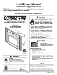
1
R
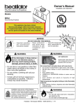
VOYAGEUR GRAND WOOD INSERT
Automatic ComEustion Control ACC
OWNER’S MANUAL
Installation and OSeration
Model:
VOYA-GRAND-MBK
VOYA-GRAND-PMH
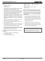
CAUTION
DO NOT DISCARD THIS MANUAL
,PSRUWDQW RSHUDWLQJ
D Q G P D L Q W H Q D Q F H
LQVWUXFWLRQVLQFOXGHG
5HDG XQGHUVWDQG DQG
IROORZWKHVHLQVWUXFWLRQV
IRUVDIHLQVWDOODWLRQDQG
RSHUDWLRQ
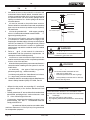
WARNING
WARNING
HOT SURFACES!
If the information in these instructions is not followed exactly, a
¿re may result causinJ SroSerty
damaJe, Sersonal inMury, or death
'RQRWVWRUHRUXVHJDVROLQHRURWKHUÀDPPDEOHYDSRUVDQGOLTXLGVLQWKHYLFLQLW\RI
WKLVRUDQ\RWKHUDSSOLDQFH
'RQRWRYHU¿UH,IKHDWHURUFKLPQH\FRQQHFWRUJORZV\RXDUHRYHU¿ULQJ2YHU¿ULQJ
ZLOOYRLG\RXUZDUUDQW\
&RPSO\ZLWKDOOPLQLPXPFOHDUDQFHVWR
FRPEXVWLEOHVDVVSHFL¿HG)DLOXUHWR
FRPSO\PD\FDXVHKRXVH¿UH
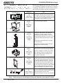
WARNING
*ODVVDQGRWKHUVXUIDFHVDUH
KRWGXULQJRSHUDWLRQ$1'
FRROGRZQ
Hot Jlass will cause Eurns
'RQRWWRXFKJODVVXQWLOLWLVFRROHG
1(9(5DOORZFKLOGUHQWRWRXFKJODVV
.HHSFKLOGUHQDZD\
&$5()8//<683(59,6(FKLOGUHQLQVDPHURRPDV
¿UHSODFH
$OHUWFKLOGUHQDQGDGXOWVWRKD]DUGVRIKLJK
WHPSHUDWXUHV
HiJh temSeratures may iJnite clothinJ or other
ÀammaEle materials
.HHSFORWKLQJIXUQLWXUHGUDSHULHVDQGRWKHU
ÀDPPDEOHPDWHULDOVDZD\
)ire RisN
NOTE
)RUXVHZLWKVROLGZRRGIXHORQO\
2WKHUIXHOVPD\RYHU¿UHDQGJHQHUDWH
SRLVRQRXVJDVHVLHFDUERQPRQR[LGH
7RREWDLQD)UHQFKWUDQVODWLRQRIWKLVPDQXDOSOHDVH
FRQWDFW\RXUGHDOHURUYLVLWZZZTXDGUD¿UHFRP
,QVWDOODWLRQDQGVHUYLFHRIWKLVDSSOLDQFHVKRXOG
EHSHUIRUPHGE\TXDOL¿HGSHUVRQQHO+HDUWK
+RPH7HFKQRORJLHVUHFRPPHQGV1),FHUWL¿HG
SURIHVVLRQDOVRUWHFKQLFLDQVVXSHUYLVHGE\DQ1),
FHUWL¿HGSURIHVVLRQDO
May 23, 2013
/HDYHWKLVPDQXDOZLWK
SDUW\ UHVSRQVLEOH IRU
XVHDQGRSHUDWLRQ
$
$) /.
3# /
!2 4
$
3RXUREWHQLUXQHWUDGXFWLRQIUDQoDLVHGHFHPDQXHOV¶LO
YRXVSODvWFRQWDFWHUYRWUHUHYHQGHXURXYLVLWH]ZZZ
TXDGUD¿UHFRP
7075-166C
Page 1
R
VOYAGEUR GRAND Wood Insert
and Welcome to the Quadra-Fire Family!
Hearth & Home Technologies welcomes you to our tradition
of excellence! In choosing a Quadra-Fire appliance, you
have our assurance of commitment to quality, durability, and
performance.
RIRXUVWRYHVLQVHUWVDQG¿UHSODFHV$QG\HWZHDUHROG
fashioned when it comes to craftsmanship. Each unit is
meticulously fabricated and gold and nickel surfaces are
KDQG¿QLVKHGIRUODVWLQJEHDXW\DQGHQMR\PHQW2XUSOHGJH
to quality is completed as each model undergoes a quality
control inspection.
This commitment begins with our research of the market,
including ‘Voice of the Customer’ contacts, ensuring we
make products that will satisfy your needs. Our Research
and Development facility then employs the world’s most
advanced technology to achieve the optimum operation
:HZLVK\RXDQG \RXUIDPLO\PDQ\\HDUVRIHQMR\PHQW LQ
the warmth and comfort of your hearth appliance. Thank
you for choosing Quadra-Fire.
NOTE: Clearances may only be reduced by means
approved by the regulatory authority having jurisdiction
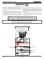
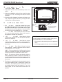
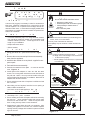
SAMPLE OF SERIAL NUMBER / SAFETY LABEL
LOCATION: UNDER ASH LIP, PULL OUT TO VIEW
LISTED ROOM HEATER, SOLID FUEL TYPE. "For Use with Solid
Wood Fuel Only." Also for use in Mobile Home.
PREVENT HOUSE FIRES
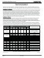
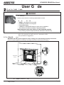
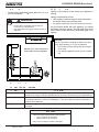
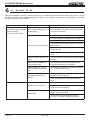
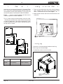
E
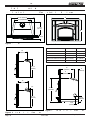
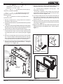
Maximum Mantel Depth - 12 inch (305mm)
Mantel
Fascia or Trim
L
SideWall
B
C
Insert
A
D
M
P
Fuel Door
E
F
Hearth Extension
Minimum Clearances To Combustible Material
Masonry, Heat Circulating & Factory-Built
Refer to Clearances on other label for Canada
USA ONLY
21.5 in.
25 in.
23 in.
11.5 in.
16 in.
8 in.
A
Sidewall to Fuel Loading Door
Mantel to Top of unit
Top Trim to Top of unit
Side Trim to Fuel Loading Door
Hearth Extension from Glass
Hearth Extenson from Fuel Loading Door
S
A
B
C
D
E
F
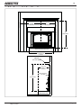
Factory-Built Floor
Protection under Hearth
Extension
Thermal & Ember Protection
Floor height 0 to 5 inches
below Insert Base: Materials
with R value of 2.38 required.
Ember Protection Only
Greater than 5 inches below
Insert Base:
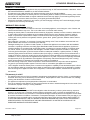
HOT WHILE IN
OPERATION DO NOT
CAUTION:
TOUCH, KEEP CHILDREN, CLOTHING AND
FURNITURE AWAY. CONTACT MAY CAUSE
SKIN BURNS. SEE NAMEPLATE AND INSTRUCTIONS.
R
Test Lab & Report
Number
Serial Number
Serial No.
Model:
007045
VOYAGEUR
ETL4001508
CONFORMS TO:
UL 1482, ULC S628-93
Mfg by:
GRAND
WOOD INSERT
1445 N. Highway, Colville, WA 99114
www.quadrafire.com
U.S. ENVIRONMENTAL PROTECTION AGENCY - Certified to comply with July 1990 particulate emission
standards.
JAN FEB MAR APR MAY JUN JUL AUG SEP OCT NOV DEC
2012 2013 2014
DO NOT REMOVE THIS LABEL
Model Name
Mfg Date
Made in U.S.A. of US and
imported parts.
7075-174
Page 2
7075-166C
May 23, 2013
R
VOYAGEUR GRAND Wood Insert
! Safety Alert Key:
DANGER! Indicates a hazardous situation which, if not avoided willUHVXOWLQGHDWKRUVHULRXVLQMXU\
WARNING! Indicates a hazardous situation which, if not avoided mayUHVXOWLQGHDWKRUVHULRXVLQMXU\
CAUTION! Indicates a hazardous situation which, if not avoided, mayUHVXOWLQPLQRURUPRGHUDWHLQMXU\
NOTICE: Indicates practices which may cause damage to the appliance or to property.
TABLE OF CONTENTS
Congratulations ...............................................................2
Sample of Safety/Serial Number Label ...........................2
Warranty Policy ...............................................................4-5
Installer’s Guide
Section 6: Getting Started
Section 1: Listing and Code Approvals
$
%
&
'
$SSOLDQFH&HUWL¿FDWLRQV.....................................6
0RELOH+RPH$SSURYHG.....................................6
*ODVV6SHFL¿FDWLRQV ..........................................6
%78(I¿FLHQF\6SHFL¿FDWLRQV ........................6
User’s Guide
Section 2: Operating Instructions
$
B.
&
D.
E.
F.
*
+
,
-
K.
L.
M.
N.
O.
P.
4
5
S.
<RXU:RRG$SSOLDQFH .......................................7
Fire Safety .........................................................8
2YHU¿ULQJ...........................................................8
Combustible/Non-combustible Material ............8
Seasoned Wood................................................8
Burning Process ................................................9
$XWRPDWLF&RPEXVWLRQ&RQWURO$&& ..............10
$LU&RQWUROV .......................................................10
%XUQ5DWHVDQG2SHUDWLQJ(I¿FLHQF\ ................10
&RUUHFW%DIÀH%ODQNHW3ODFHPHQW ..................11
Building a Fire ...................................................12
Fuel Reloading Instructions...............................12
Wood Fuel & Storage ........................................13
Blower Control Box Snap Disc Operations .......14
Blower Operating Instructions ...........................14
Clear Space ......................................................15
)UHTXHQWO\$VNHG4XHVWLRQV .............................15
2SDFLW\6PRNH ...............................................15
Quick Start Guide ..............................................16
Section 3: Maintenance and Service
$ 'LVSRVDORI$VKHV .............................................17
B. Chimney & Chimney Connector
Inspection/Cleaning...........................................17
& $SSOLDQFH,QVSHFWLRQ5RXWLQH .........................17
D. Cleaning of Plated Surfaces..............................17
E. Glass Cleaning ..................................................18
F. Firebrick Inspection & Replacement Instruction 18
G. Quick Reference Maintenance Guide ...............19
Section 7: Dimensions and Clearances
*ODVV5HSODFHPHQW ...........................................21
Snap Disc Replacement....................................21
Wiring Diagram .................................................21
Blower Replacement .........................................22
'RRU+DQGOH$VVHPEO\ .....................................23
%DIÀH&HUDPLF%ODQNHW5HPRYDO ...................23
7XEH&KDQQHO$VVHPEO\5HSODFHPHQW .............24
May 23, 2013
$
B.
C.
D.
E.
F.
G.
+
I.
J.
K.
9HQWLQJ6\VWHPV ...............................................34
Inspections ........................................................34
Larger Chimneys ...............................................34
Masonry Chimney .............................................34-35
Metal Heat Circulating Chimney........................36
Prefabricated Metal Chimney ............................36
Securing Chimney Components .......................37
$OWHULQJWKH)LUHSODFH ........................................37
Factory-Built Solid Fuel Fireplaces ...................37
Ovalizing Round Stainless Steel Liners ............38
Chimney Height / Rise and Run ........................38
Section 9: Appliance Set-up
$
%
C.
D.
(
F.
G.
+
I.
2XWVLGH$LU,QVWDOODWLRQ ......................................39
2SWLRQDO(OERZ)OXH$GDSWHU,QVWDOODWLRQ ..........40
Securing Stove Pipe/Liner to Flue Collar ..........40
Leveling Legs ....................................................40
6HFXULQJ$SSOLDQFHWR6WRYH3LSH/LQHU ............41
Standard Surround & Trim Installation ..............41
Standard Surround & Cast Trim, .......................42
$OO&DVW6XUURXQG ..............................................43
Blower Cord Installation - Left Side ...................43-45
Section 10: Moble Home Installation ................. 46
Section 5: Service Parts Replacement
$
B.
C.
D.
(
)
*
$ $SSOLDQFH'LPHQVLRQV.......................................30
B. Clearances to Combustibles 8/DQG8/&
and Hearth Protection Requirements ................31-32
& $OWHUQDWH)ORRU3URWHFWLRQ&DOFXODWLRQ...............33
Section 8: Chimney Systems
Section 4: Troubleshooting Guide ..................... 20
$ 'HVLJQ,QVWDOODWLRQ/RFDWLRQ
Considerations ..................................................25
B. Draft ..................................................................25
C. Negative Pressure.............................................26
' /RFDWLQJ<RXU$SSOLDQFHDQG&KLPQH\ .............27
E. Chimney Termination Requirements.................27
F. 2-10-3 Rule .......................................................28
G. Tools and Supplies Needed ..............................29
H. Fire Safety .........................................................29
, ,QVSHFW$SSOLDQFHDQG&RPSRQHQWV
and Pre-Burn Checklist .....................................29
Section 11: Reference Materials
7075-166C
$
%
C.
D.
E.
([SORGHG'UDZLQJV ...........................................47
6HUYLFH3DUWV$FFHVVRULHV .............................48-52
Service Maintenance Log..................................53-54
Homeowners notes ...........................................55
Contact Information ...........................................56
Page 3
R
VOYAGEUR GRAND Wood Insert
Hearth & Home Technologies Inc.
LIMITED LIFETIME WARRANTY
Hearth & Home Technologies Inc., on behalf of its hearth brands (”HHT”), extends the following warranty for
HHT gas, wood, pellet, coal and electric hearth appliances that are purchased from an HHT authorized dealer.
WARRANTY COVERAGE:
HHT warrants to the original owner of the HHT appliance at the site of installation, and to any transferee taking ownership
of the appliance at the site of installation within two years following the date of original purchase, that the HHT appliance
will be free from defects in materials and workmanship at the time of manufacture. After installation, if covered components manufactured by HHT are found to be defective in materials or workmanship during the applicable warranty period,
HHT will, at its option, repair or replace the covered components. HHT, at its own discretion, may fully discharge all of its
obligations under such warranties by replacing the product itself or refunding the verified purchase price of the product
itself. The maximum amount recoverable under this warranty is limited to the purchase price of the product. This warranty
is subject to conditions, exclusions and limitations as described below.
WARRANTY PERIOD:
Warranty coverage begins on the date of original purchase. In the case of new home construction, warranty coverage
begins on the date of first occupancy of the dwelling or six months after the sale of the product by an independent,
authorized HHT dealer/ distributor, whichever occurs earlier. The warranty shall commence no later than 24 months
following the date of product shipment from HHT, regardless of the installation or occupancy date. The warranty period for
parts and labor for covered components is produced in the following table.
The term “Limited Lifetime” in the table below is defined as: 20 years from the beginning date of warranty coverage for
gas appliances, and 10 years from the beginning date of warranty coverage for wood, pellet, and coal appliances. These
time periods reflect the minimum expected useful lives of the designated components under normal operating conditions.
Warranty Period
Parts
Labor
1 Year
2 years
HHT Manufactured Appliances and Venting
Gas
X
X
Wood
X
X
X
3 years
Pellet
EPA
Wood
Coal
X
X
X
X
X
X
X
X
X
Components Covered
Electric Venting
X
X
All parts and material except as
covered by Conditions,
Exclusions, and Limitations
listed
Igniters, electronic components,
and glass
Factory-installed blowers
Molded refractory panels
Firepots and burnpots
X
5 years
1 year
7 years
3 years
10
years
1 year
X
Limited
3 years
Lifetime
X
X
X
X
X
90 Days
X
X
X
X
X
X
X
X
Castings and baffles
X
X
Manifold tubes,
HHT chimney and termination
Burners, logs and refractory
Firebox and heat exchanger
X
X
All replacement parts
beyond warranty period
See conditions, exclusions, and limitations on next page.
4021-645C 12-29-10
Page 4
Page 1 of 2
7075-166C
May 23, 2013
R
VOYAGEUR GRAND Wood Insert
WARRANTY CONDITIONS:
7KLVZDUUDQW\RQO\FRYHUV++7DSSOLDQFHVWKDWDUHSXUFKDVHGWKURXJKDQ++7DXWKRUL]HGGHDOHURUGLVWULEXWRU$OLVWRI
++7DXWKRUL]HGGHDOHUVLVDYDLODEOHRQWKH++7EUDQGHGZHEVLWHV
7KLVZDUUDQW\LVRQO\YDOLGZKLOHWKH++7DSSOLDQFHUHPDLQVDWWKHVLWHRIRULJLQDOLQVWDOODWLRQ
&RQWDFW\RXULQVWDOOLQJGHDOHUIRUZDUUDQW\VHUYLFH,IWKHLQVWDOOLQJGHDOHULVXQDEOHWRSURYLGHQHFHVVDU\SDUWVFRQWDFW
WKHQHDUHVW++7DXWKRUL]HGGHDOHURUVXSSOLHU$GGLWLRQDOVHUYLFHIHHVPD\DSSO\LI\RXDUHVHHNLQJZDUUDQW\VHUYLFH
IURPDGHDOHURWKHUWKDQWKHGHDOHUIURPZKRP\RXRULJLQDOO\SXUFKDVHGWKHSURGXFW
&KHFNZLWK\RXUGHDOHULQDGYDQFHIRUDQ\FRVWVWR\RXZKHQDUUDQJLQJDZDUUDQW\FDOO7UDYHODQGVKLSSLQJFKDUJHV
IRUSDUWVDUHQRWFRYHUHGE\WKLVZDUUDQW\
WARRANTY EXCLUSIONS:
7KLVZDUUDQW\GRHVQRWFRYHUWKHIROORZLQJ
&KDQJHVLQVXUIDFHILQLVKHVDVDUHVXOWRIQRUPDOXVH$VDKHDWLQJDSSOLDQFHVRPHFKDQJHVLQFRORURILQWHULRUDQG
H[WHULRUVXUIDFHILQLVKHVPD\RFFXU7KLVLVQRWDIODZDQGLVQRWFRYHUHGXQGHUZDUUDQW\
'DPDJHWRSULQWHGSODWHGRUHQDPHOHGVXUIDFHVFDXVHGE\ILQJHUSULQWVDFFLGHQWVPLVXVHVFUDWFKHVPHOWHGLWHPV
RURWKHUH[WHUQDOVRXUFHVDQGUHVLGXHVOHIWRQWKHSODWHGVXUIDFHVIURPWKHXVHRIDEUDVLYHFOHDQHUVRUSROLVKHV
5HSDLURUUHSODFHPHQWRISDUWVWKDWDUHVXEMHFWWRQRUPDOZHDUDQGWHDUGXULQJWKHZDUUDQW\SHULRG7KHVHSDUWV
LQFOXGHSDLQWZRRGSHOOHWDQGFRDOJDVNHWVILUHEULFNVJUDWHVIODPHJXLGHVOLJKWEXOEVEDWWHULHVDQGWKHGLVFRORUDWLRQRIJODVV
0LQRUH[SDQVLRQFRQWUDFWLRQRUPRYHPHQWRIFHUWDLQSDUWVFDXVLQJQRLVH7KHVHFRQGLWLRQVDUHQRUPDODQGFRPSODLQWVUHODWHGWRWKLVQRLVHDUHQRWFRYHUHGE\WKLVZDUUDQW\
'DPDJHVUHVXOWLQJIURPIDLOXUHWRLQVWDOORSHUDWHRUPDLQWDLQWKHDSSOLDQFHLQDFFRUGDQFHZLWKWKHLQVWDOODWLRQ
LQVWUXFWLRQVRSHUDWLQJLQVWUXFWLRQVDQGOLVWLQJDJHQWLGHQWLILFDWLRQODEHOIXUQLVKHGZLWKWKHDSSOLDQFHIDLOXUHWR
LQVWDOOWKHDSSOLDQFHLQDFFRUGDQFHZLWKORFDOEXLOGLQJFRGHVVKLSSLQJRULPSURSHUKDQGOLQJLPSURSHURSHUDWLRQDEXVHPLVXVHFRQWLQXHGRSHUDWLRQZLWKGDPDJHGFRUURGHGRUIDLOHGFRPSRQHQWVDFFLGHQWRULPSURSHUO\
LQFRUUHFWO\SHUIRUPHGUHSDLUVHQYLURQPHQWDOFRQGLWLRQVLQDGHTXDWHYHQWLODWLRQQHJDWLYHSUHVVXUHRUGUDIWLQJ
FDXVHGE\WLJKWO\VHDOHGFRQVWUXFWLRQVLQVXIILFLHQWPDNHXSDLUVXSSO\RUKDQGOLQJGHYLFHVVXFKDVH[KDXVWIDQVRU
IRUFHGDLUIXUQDFHVRURWKHUVXFKFDXVHVXVHRIIXHOVRWKHUWKDQWKRVHVSHFLILHGLQWKHRSHUDWLQJLQVWUXFWLRQV
LQVWDOODWLRQRUXVHRIFRPSRQHQWVQRWVXSSOLHGZLWKWKHDSSOLDQFHRUDQ\RWKHUFRPSRQHQWVQRWH[SUHVVO\DXWKRUL]HG
DQGDSSURYHGE\++7PRGLILFDWLRQRIWKHDSSOLDQFHQRWH[SUHVVO\DXWKRUL]HGDQGDSSURYHGE\++7LQZULWLQJ
DQGRULQWHUUXSWLRQVRUIOXFWXDWLRQVRIHOHFWULFDOSRZHUVXSSO\WRWKHDSSOLDQFH
1RQ++7YHQWLQJFRPSRQHQWVKHDUWKFRPSRQHQWVRURWKHUDFFHVVRULHVXVHGLQFRQMXQFWLRQZLWKWKHDSSOLDQFH
$Q\SDUWRIDSUHH[LVWLQJILUHSODFHV\VWHPLQZKLFKDQLQVHUWRUDGHFRUDWLYHJDVDSSOLDQFHLVLQVWDOOHG
++7¶VREOLJDWLRQXQGHUWKLVZDUUDQW\GRHVQRWH[WHQGWRWKHDSSOLDQFH¶VFDSDELOLW\WRKHDWWKHGHVLUHGVSDFH,QIRUPDWLRQLVSURYLGHGWRDVVLVWWKHFRQVXPHUDQGWKHGHDOHULQVHOHFWLQJWKHSURSHUDSSOLDQFHIRUWKHDSSOLFDWLRQ&RQVLGHUDWLRQPXVWEHJLYHQWRDSSOLDQFHORFDWLRQDQGFRQILJXUDWLRQHQYLURQPHQWDOFRQGLWLRQVLQVXODWLRQDQGDLUWLJKWQHVVRI
WKHVWUXFWXUH
This warranty is void if:
7KHDSSOLDQFHKDVEHHQRYHUILUHGRURSHUDWHGLQDWPRVSKHUHVFRQWDPLQDWHGE\FKORULQHIOXRULQHRURWKHUGDPDJLQJ
FKHPLFDOV2YHUILULQJFDQEHLGHQWLILHGE\EXWQRWOLPLWHGWRZDUSHGSODWHVRUWXEHVUXVWFRORUHGFDVWLURQEXEEOLQJ
FUDFNLQJDQGGLVFRORUDWLRQRIVWHHORUHQDPHOILQLVKHV
7KHDSSOLDQFHLVVXEMHFWHGWRSURORQJHGSHULRGVRIGDPSQHVVRUFRQGHQVDWLRQ
7KHUHLVDQ\GDPDJHWRWKHDSSOLDQFHRURWKHUFRPSRQHQWVGXHWRZDWHURUZHDWKHUGDPDJHZKLFKLVWKHUHVXOWRIEXW
QRWOLPLWHGWRLPSURSHUFKLPQH\RUYHQWLQJLQVWDOODWLRQ
LIMITATIONS OF LIABILITY:
7KHRZQHU¶VH[FOXVLYHUHPHG\DQG++7¶VVROHREOLJDWLRQXQGHUWKLVZDUUDQW\XQGHUDQ\RWKHUZDUUDQW\H[SUHVVRU
LPSOLHGRULQFRQWUDFWWRUWRURWKHUZLVHVKDOOEHOLPLWHGWRUHSODFHPHQWUHSDLURUUHIXQGDVVSHFLILHGDERYH,QQR
HYHQWZLOO++7EHOLDEOHIRUDQ\LQFLGHQWDORUFRQVHTXHQWLDOGDPDJHVFDXVHGE\GHIHFWVLQWKHDSSOLDQFH6RPHVWDWHV
GRQRWDOORZH[FOXVLRQVRUOLPLWDWLRQRILQFLGHQWDORUFRQVHTXHQWLDOGDPDJHVVRWKHVHOLPLWDWLRQVPD\QRWDSSO\WR\RX
7KLVZDUUDQW\JLYHV\RXVSHFLILFULJKWV\RXPD\DOVRKDYHRWKHUULJKWVZKLFKYDU\IURPVWDWHWRVWDWH(;&(3772
7+((;7(173529,'('%</$:++70$.(612(;35(66:$55$17,(627+(57+$17+(:$55$17<
63(&,),('+(5(,17+('85$7,212)$1<,03/,(':$55$17<,6/,0,7('72'85$7,212)7+(
(;35(66(':$55$17<63(&,),('$%29(
4021-645C 12-29-10
May 23, 2013
Page 2 of 2
7075-166C
Page 5
R
VOYAGEUR GRAND Wood Insert
st n
nd
ode A
ro
s
D BTU Ef¿ciency Speci¿cations
A Appliance Certi¿cation
ode
or tor
Re ort No
e
92<$*(85*5$1':RRG,QVHUW
EPA Certi¿ed:
3.1 grams per hour
Intertek
Ef¿ciency:
80
UO t
100868597PRT-001
Solid Fuel Type, Listed Room Heater
t nd rd
L1482 and LC S628-93 and
80+8'0RELOH+RPH
$SSURYHG
t
10,700 to 28,500 per hr
e tn
Vent
t
1,100 to 2,800 sq ft depending on climate zone
e
re o
6 inches
e
2.35 cubic feet
Wood en t
e
NOTE This installation must conform with local codes. In the
absence of local codes you must comply with the L1482,
80+8'DQG13)$LQWKH86$DQGWKH8/&6
DQG&$1&6$%,QVWDOODWLRQ&RGHVLQ&DQDGD
o
est n
NR
e
or tor
ro ed
o eA
s
O
N t on
A
7KHVWUXFWXUDOLQWHJULW\RIWKHPRELOHKRPHÀRRUFHLOing, and walls must be maintained.
The appliance must be properly grounded to the
frame of the mobile home with 8 copper ground
wire, and use only listed connector pipe.
2XWVLGH$LU.LWSDUW2$.$&&PXVWEHLQVWDOOHGLQD
mobile home installation.
C Glass Speci¿cations
This stove is equipped with 5mm ceramic glass. Replace
glass only with 5mm ceramic glass. Please contact your
dealer for replacement glass.
389 lbs
Fire Risk.
This appliance is approved for mobile home installations when not installed in a sleeping room and when
an outside combustion air inlet is provided.
t
:$51,1*
Re o n ed
ro ed
Cord Wood
n We
7KH4XDGUD)LUH92<$*(85*5$1'PHHWVWKH86(QYLURQPHQWDO 3URWHFWLRQ$JHQF\¶V SDUWLFXODWH HPLVVLRQ
standards.
Interte
est
21 inches
Hearth & Home Technologies disclaims any
responsibility for, and the warranty will be
voided by, the following actions
,QVWDOODWLRQDQGXVHRIDQ\GDPDJHGDSSOLDQFH
0RGL¿FDWLRQRIWKHDSSOLDQFH
,QVWDOODWLRQ RWKHU WKDQ DV LQVWUXFWHG E\ +HDUWK +RPH
Technologies.
,QVWDOODWLRQDQGRUXVHRIDQ\FRPSRQHQWSDUWQRWDSSURYHG
by Hearth & Home Technologies.
2SHUDWLQJ DSSOLDQFH ZLWKRXW IXOO\ DVVHPEOLQJ DOO
components.
2SHUDWLQJDSSOLDQFHZLWKRXWOHJVDWWDFKHGLIVXSSOLHGZLWK
XQLW
'R1272YHU¿UH,IDSSOLDQFHRUFKLPQH\FRQQHFWRUJORZV
\RXDUHRYHU¿ULQJ
$Q\VXFKDFWLRQWKDWPD\FDXVHD¿UHKD]DUG
,PSURSHU LQVWDOODWLRQ DGMXVWPHQW DOWHUDWLRQ VHUYLFH RU
PDLQWHQDQFHFDQFDXVHLQMXU\RUSURSHUW\GDPDJH
)RUDVVLVWDQFHRUDGGLWLRQDOLQIRUPDWLRQFRQVXOWDTXDOL¿HG
installer, service agency or your dealer.
NOTE Hearth & Home Technologies, manufacturer of
this appliance, reserves the right to alter its products,
WKHLUVSHFL¿FDWLRQVDQGRUSULFHZLWKRXWQRWLFH
Quadra-Fire is a registered trademark of Hearth & Home
Technologies.
Page 6
7075-166C
May 23, 2013
R
VOYAGEUR GRAND Wood Insert
User G de
O er t n Instr
t ons
WARNING
O
UR A E
*ODVVDQGRWKHUVXUIDFHVDUHKRWGXULQJRSHUDWLRQ$1'FRROGRZQ
ot
ss
se
rns
DO NO touch glass until it is cooled
1(9(5DOORZFKLOGUHQWRWRXFKJODVV
.HHSFKLOGUHQDZD\
&$5()8//<683(59,6(FKLOGUHQLQVDPHURRPDVDSSOLDQFH
$OHUWFKLOGUHQDQGDGXOWVWRKD]DUGVRIKLJKWHPSHUDWXUHV
High temperatures may ignite clothing or other Àammable materials
.HHSFORWKLQJIXUQLWXUHGUDSHULHVDQGRWKHUÀDPPDEOHPDWHULDOVDZD\
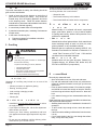
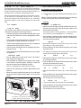
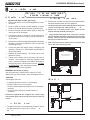
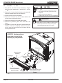
A Yo r Wood A
n e
If you expect that children may come into contact with this appliance, we recommend a barrier such as a decorative screen.
See your dealer for suggestions.
WARNING! DO NOT operate appliance before reading and understanding operating instructions.
)DLOXUHWRRSHUDWHDSSOLDQFHDFFRUGLQJWRRSHUDWLQJLQVWUXFWLRQVFRXOGFDXVH¿UHRULQMXU\
Door
Handle
Surround and
Trim Set
Burn Rate
Control
ACC Start-up Air
Control
Convection Fan
Blower Controls
re
May 23, 2013
Gener
O er t n
rts
7075-166C
Page 7
R
VOYAGEUR GRAND Wood Insert
re
et
7R SURYLGH UHDVRQDEOH ¿UH VDIHW\ WKH IROORZLQJ VKRXOG EH
given serious consideration
,QVWDOO DW OHDVW RQH VPRNH GHWHFWRU RQ HDFK ÀRRU RI
your home to ensure your safety. They should be
located away from the heating appliance and close
to the sleeping areas. Follow the smoke detector
manufacturer s placement and installation instructions,
and be sure to maintain regularly.
$FRQYHQLHQWO\ORFDWHG&ODVV$¿UHH[WLQJXLVKHU
$SUDFWLFHGHYDFXDWLRQSODQFRQVLVWLQJRIDWOHDVWWZR
escape routes.
,QWKHHYHQWRIDFKLPQH\¿UH
Prepare occupants for immediate evacuation
1RWLI\¿UHGHSDUWPHQW
C Over¿ring
WARNING
re R s
'RQRWRYHU¿UH
2YHU¿ULQJ PD\ LJQLWH FUHRVRWH RU ZLOO GDPDJH
the stove and chimney.
7RSUHYHQWRYHU¿ULQJ\RXUVWRYH'2127
:DUSHGDLUWXEH
'HWHULRUDWHGUHIUDFWRU\EULFNUHWDLQHUV
'HWHULRUDWHGEDIÀHDQGRWKHULQWHULRUFRPSRQHQWV
D
o
st
e Non o
st
e
ter
s
a.
E
Hearth & Home Technologies WILL NOT warranty appliDQFHVWKDWH[KLELWHYLGHQFHRIRYHU¿ULQJ(YLGHQFHRI
RYHU¿ULQJLQFOXGHVEXWLVQRWOLPLWHGWR
8VHÀDPPDEOHOLTXLGV
2YHUORDGZLWKZRRG
%XUQWUDVKRUODUJHDPRXQWVRIVFUDSOXPEHU
3HUPLWWRRPXFKDLUWRWKH¿UH
8VHRISURFHVVHGVROLGIXHO¿UHORJV
o
st e
ter
Material made of or surfaced with wood, compressed
SDSHU SODQW ¿EHUV SODVWLFV RU DQ\ PDWHULDO FDSDEOH
RI LJQLWLQJ DQG EXUQLQJ ZKHWKHU ÀDPHSURRIHG RU QRW
plastered or unplastered.
Non o
st e
ter
Material which will not ignite and burn. Such materials are
those consisting entirely of steel, iron, brick, tile, slate,
glass or plasters, or any combination thereof.
0DWHULDOV WKDW DUH UHSRUWHG DV SDVVLQJ$670 ( Standard Test Method for Behavior of Materials in a
ertical Tube Furnance at 750 oC and L763 shall be
considered non-combustible materials.
Non o
st e e nt
ter
Sealants which will not ignite and burn Rutland, Inc.
Fireplace Mortar 63, Rutland 76R, Nuflex 304, GE
579RU*(57%RUHTXLYDOHQW
E
e soned Wood
Burn only dry seasoned wood.
to s o O er r n
6WRUHZRRGXQGHUFRYHURXWRIWKHUDLQDQGVQRZ
6\PSWRPV RI RYHU¿ULQJ PD\ LQFOXGH RQH RU PRUH RI WKH 'U\DQGZHOOVHDVRQHGZRRGZLOOQRWRQO\PLQLPL]HWKH
following
chance of creosote formation, but will give you the most
HI¿FLHQW¿UH
&KLPQH\FRQQHFWRURUDSSOLDQFHJORZLQJ
(YHQGU\ZRRGFRQWDLQVDWOHDVWPRLVWXUHE\ZHLJKW
5RDULQJUXPEOLQJQRLVHV
and should be burned hot enough to keep the chimney
/RXGFUDFNLQJRUEDQJLQJVRXQGV
hot for as long as it takes to dry the wood out - about one
hour.
0HWDOZDUSLQJ
,WLVDZDVWHRIHQHUJ\WREXUQXQVHDVRQHGZRRGRIDQ\
&KLPQH\¿UH
kind.
'HDGZRRGO\LQJRQWKHIRUHVWÀRRUVKRXOGEHFRQVLGHUHGZHW
W t o Do Yo r A
n e s O er r n
and requires full seasoning time.
,PPHGLDWHO\close the door and air controls to reduce
6WDQGLQJGHDGZRRGFDQEHFRQVLGHUHGWREHDERXW
DLUVXSSO\WRWKH¿UH
seasoned.
7RWHOOLIZRRGLVGU\HQRXJKWREXUQFKHFNWKHHQGVRI
,I\RXVXVSHFWDFKLPQH\¿UHFDOOWKH¿UHGHSDUWPHQW
the
logs.
and evacuate your house.
,IWKHUHDUHFUDFNVUDGLDWLQJLQDOOGLUHFWLRQVIURPWKHFHQWHU
&RQWDFW \RXU ORFDO FKLPQH\ SURIHVVLRQDO DQG KDYH
it is dry.
your appliance and stove pipe inspected for any dam
,I\RXUZRRGVL]]OHVLQWKH¿UHHYHQWKRXJKWKHVXUIDFH
age.
is dry, it may not be fully cured.
'RQRWXVH\RXUDSSOLDQFHXQWLOWKHFKLPQH\SURIHVsional informs you it is safe to do so.
Page 8
7075-166C
May 23, 2013
R
VOYAGEUR GRAND Wood Insert
rn n
e ond t
ro ess
In recent years there has been an increasing concern about
air quality. Much of the blame for poor air quality has been
placed on the burning of wood for home heating.
In order to improve the situation, we at Quadra-Fire have
developed cleaner-burning wood appliances that surpass
the requirements for emissions established by our governing
agencies.
These wood appliances must be properly operated in order
to ensure that they perform the way they are designed to
perform.
,QWKHVHFRQGDU\VWDJHZRRGJLYHVRIIÀDPPDEOHJDVHVZKLFK
EXUQDERYHWKHIXHOZLWKEULJKWÀDPHV
During this stage of burning
7KHÀDPHVPXVWEHPDLQWDLQHGDQGQRWDOORZHGWRJRRXW
toHQVXUHWKHFOHDQHVWSRVVLEOH¿UH
,IWKHÀDPHVWHQGWRJRRXWLWLVVHWWRRORZIRU\RXUEXUQing conditions.
The air control located at the upper right hand corner is used to
DGMXVWIRUEXUQUDWHV7KLVLVFDOOHGWKH%XUQ5DWH$LU&RQWURO.
re
on
e
n
NO I E Improper operation can turn any wood appliance into a smoldering environmental hazard.
nd n or
rst t
e
It helps to know a little about the actual process of burning in
order to understand what goes on inside the appliance. The
¿UVWVWDJHRIEXUQLQJLVFDOOHGWKHNLQGOLQJVWDJH
In this stage
Wood is heated to a temperature high enough to evaporate the moisture present in all wood.
:RRGZLOOUHDFKWKHERLOLQJSRLQWRIZDWHU)DQGZLOO
not get any hotter until the water is evaporated.
This process takes heat from the coals and tends to cool the
appliance.
Fire requires three things to burn
)XHO
$LU
+HDW
e
t
e
7KH¿QDOVWDJHRIEXUQLQJLVWKHFKDUFRDOVWDJH7KLVRFFXUV
ZKHQ WKH ÀDPPDEOH JDVHV KDYH EHHQ PRVWO\ EXUQHG DQG
only charcoal remains. This is a naturally clean portion of
WKHEXUQ7KHFRDOVEXUQZLWKKRWEOXHÀDPHV
It is very important to reload your appliance while enough
lively hot coals remain in order to provide the amount of
heat needed to dry and rekindle the next load of wood.
,WLVEHVWWRRSHQWKH%XUQ5DWH$LUDQG6WDUW8S$LU&RQtrols before reloading. This livens up the coalbed and
UHGXFHVH[FHVVLYHHPLVVLRQVRSDFLW\VPRNH
2SHQGRRUVORZO\VRWKDWDVKRUVPRNHGRHVQRWH[LWDSpliance through opening.
Break up any large chunks and distribute the coals so
that the new wood is laid on hot coals.
$LUTXDOLW\LVLPSRUWDQWWRDOORIXVDQGLIZHFKRRVHWRXVH
wood to heat our homes we should do so responsibly.
We need to learn to burn in the cleanest way possible allowing us to continue using our wood appliances for many
years to come.
If heat is robbed from the appliance during the drying stage,
the new load of wood has reduced the chances for a good
clean burn.
,WLVDOZD\VEHVWWREXUQGU\VHDVRQHG¿UHZRRG:KHQWKH
wood isn t dry, you must open the air controls and burn at a
high burn setting for a longer time to start it burning.
7KH KHDW JHQHUDWHG IURP WKH ¿UH VKRXOG EH ZDUPLQJ \RXU
KRPH DQG HVWDEOLVKLQJ WKH ÀXH GUDIW QRW HYDSRUDWLQJ WKH
moisture out of wet, unseasoned wood, resulting in wasted
heat.
May 23, 2013
7075-166C
Page 9
R
VOYAGEUR GRAND Wood Insert
G A to
t
o
st on
I Burn Rates and Operating Ef¿ciency
ontro A
7\SLFDOO\ZKHQ\RXEXLOGD¿UH\RXRSHQWKHDLUFRQWUROVIXOO\
DQGPRQLWRUWKH¿UHWRSUHYHQWLWIURPJRLQJLQWRDQRYHU¿UH
situation and/or burning your wood up too quickly before you
shut down the air controls to the desired burn rate.
:KHQXVLQJWKH$XWRPDWLF&RPEXVWLRQ&RQWURO$&&V\VWHP
\RX GR QRW KDYH WR FRQWLQXDOO\ PRQLWRU WKH ¿UH 2QFH \RX
VHWWKH$&&V\VWHPLWZLOOFRQWUROWKH¿UHIRU\RX)ROORZWKH
instructions below to learn how to operate your stove with
ease.
Ar
For maximum operating ef¿ciency
1. Burn dry, well-seasoned wood.
2. Follow these burn rate instructions below and refer to
re
NO E 7KHVHDUHJXLGHOLQHV$FWXDOVHWWLQJVPD\YDU\ZLWKW\SH
of wood, chimney draft, altitude and other variables.
rn R tes
ontro s
t rt U A r
t rt n
ontro
7KH IXQFWLRQ RI WKH 6WDUW8S$LU &RQWURO LV WR DFWLYDWH WKH
$XWRPDWLF&RPEXVWLRQ&RQWUROV\VWHP$&&
3XVKWKH6WDUW8S$LU&RQWURODOOWKHZD\EDFNXQWLOLWVWRSV
and then pull forward to the front of the appliance until it
stops.
re
7he air channel opens and allows air to enter the front of
the appliance for approximately 20-25 minutes.
re nd Re o d n
2SHQERWKFRQWUROVIXOO\E\UDLVLQJWKH%XUQ5DWH$LU&RQWURODOOWKHZD\XSXQWLOLWVWRSVDQGSXVKWKH6WDUWXS$LU
Control back until it stops.
The blower tends to cool the appliance. Leave the blower
off until the burn is well established, i.e., 30 minutes.
$IWHUORDGLQJWKHDSSOLDQFHZLWKZRRGDQGVWDUWLQJWKH¿UH
set both controls to the desired setting by following the
burn rate instructions below.
rn R te
e t
7KHDLUFKDQQHOJUDGXDOO\VKXWVGRZQXQWLOLWLVFRPSOHWHO\
closed at the end of the 20-25 minutes.
5DLVHWKH%XUQ5DWH$LU&RQWURODOOWKHZD\XSXQWLOLWVWRSV
WRSPDUNHUWRDIXOO\RSHQSRVLWLRQ
7KH¿UHLVQRZFRQWUROOHGE\WKHDLUVXSSOLHGE\WKH%XUQ
5DWH$LU&RQWURO
re
3XVKWKH6WDUW8S$LU&RQWURODOOWKHZD\EDFNXQWLOLWVWRSV
and leave it there.
7KLVIXQFWLRQVKRXOGEHSHUIRUPHGHDFKWLPH\RXUHORDG
the appliance.
rn R te A r ontro
7KLVVHWWLQJRYHUULGHVWKHWLPHUV\VWHP$&&VR\RXPXVW
PRQLWRUWKH¿UHFORVHO\ZKLOHLQWKLVVHWWLQJ
ed
rn R te
to
U r
7KH DLU VXSSO\ HQWHUV DW WKH XSSHU IURQW RI WKH ¿UHER[
5DLVHWKH%XUQ5DWH$LU&RQWURODOOWKHZD\XSXQWLOLWVWRSV
near the top of the glass door.
to a fully open position.
This preheated air supplies the necessary fresh oxygen
3XVKWKH6WDUW8S$LU&RQWURODOOWKHZD\EDFNXQWLOLWVWRSV
to mix with the unburned gases, helping to create the
and then pull forward until it stops.
second, third and fourth combustion process.
7KLVDFWLYDWHVWKHWLPHUV\VWHP$&&
7KLVDLULVUHJXODWHGE\WKH%XUQ5DWH$LU&RQWURO
ed
o
rn R te
to
U r
There are four settings High, Medium-High, Medium-Low
5DLVHWKH%XUQ5DWH$LU&RQWUROXSIURPORZHVWSRVLand Low.
tion.
When the control is raised all the way up it is on the High
setting and when pushed all the down it is on the Low 3XVKWKH6WDUW8S$LU&RQWURODOOWKHZD\EDFNXQWLOLWVWRSV
and then pull forward until it stops.
setting.
HIGH
Burn Rate Control
7KLVDFWLYDWHVWKHWLPHUV\VWHP$&&
o
LOW
rn R te
eo
U r
/HDYHWKH%XUQ5DWH$LU&RQWURODWLWVORZHVWSRVLWLRQ
3XVKWKH6WDUW8S$LU&RQWURODOOWKHZD\EDFNXQWLOLWVWRSV
and then pull forward until it stops.
7KLVDFWLYDWHVWKHWLPHUV\VWHP$&&
ACC Start-up
Air Control
To activate: Push back until it stops
and then pull forward until it stops
re
Page 10
t rt
nd
rn R te A r
ontro s
7075-166C
May 23, 2013
R
VOYAGEUR GRAND Wood Insert
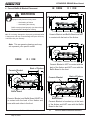
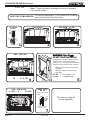
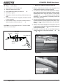
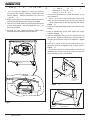
- Correct BafÀe BlanNet Placement
IN ORRE
O I ION
WARNING
re R s
,PSURSHUEDIÀHSODFHPHQWPD\FDXVH
2YHUKHDWLQJRI¿UHER[
Overheating the chimney
%DIÀHPXVWEHSODFHGSURSHUO\VHHLQVWUXFWLRQV
5HSODFHEDIÀHLIGDPDJHGRUPLVVLQJ
NO E $PLVVLQJGDPDJHGRULPSURSHUO\SRVLWLRQHGEDIÀH
LVGDQJHURXVDQGPD\FDXVHGDPDJHDQGSRRUHI¿FLHQF\
It will also void your warranty.
&HUDPLF%ODQNHWDQG%DIÀH%RDUGDUH127
LQFRQWDFWZLWKWKHEDFNRIWKH¿UHER[
Note: 7KLVDUHJHQHULFGUDZLQJVDQGPD\
QRWUHSUHVHQW\RXUVSHFL¿FPRGHO
ORRE
O I ION
Back of Firebox
Ceramic Blanket
Ceramic Blanket is NOT in contact with the
EDFNRIWKH¿UHER[DQG127HYHQZLWKWKH
%DIÀH%RDUGLQWKHIURQW
Back of Firebox
Ceramic Blanket
Baffle Board
&HUDPLF%ODQNHWDQG%DIÀH%RDUG0867EH
LQ FRQWDFW ZLWK WKH EDFN RI WKH ¿UHER[ DQG
even with each other in the front.
re
Correct BafÀe and BlanNet Positions
May 23, 2013
Baffle Board
Ceramic Blanket is bunched up at the back
RIWKH¿UHER[DQG127HYHQZLWKWKH%DIÀH
Board in the front.
re
7075-166C
Incorrect BafÀe and BlanNet Positions
Page 11
R
VOYAGEUR GRAND Wood Insert
dn A
re
e Re o d n Instr
WARNING
1. This appliance has a large door with an exceptional
YLHZRIWKH¿UH
re R s
Keep combustible materials, gasoline
DQGRWKHUÀDPPDEOHYDSRUVDQGOLTXLGV
clear of appliance.
'R127VWRUHÀDPPDEOHPDWHULDOVLQWKHDSSOLDQFH¶V
vicinity.
2SHQVWRDERXWGHJUHHVDQGKDVDEXLOWLQVWRS
'RRURSHQVLQFKHVPPZKLFKJRHVEH\RQG
WKH VWDQGDUG VL]H KHDUWK SDG FRYHULQJ WKH ÀRRU LQ
front of the appliance.
'212786(*$62/,1(/$17(51)8(/
.(526(1(&+$5&2$//,*+7(5)/8,'25
6,0,/$5/,48,'67267$5725³)5(6+(183´$
),5(,17+,6+($7(5
.HHSDOOVXFKOLTXLGVZHOODZD\IURPWKHKHDWHUZKLOHLW
is in use.
0D\ZDQWWRXVHDKHDUWKUXJLQIURQWRIWKHKHDUWK
SDGWRSURWHFWWKHÀRRULQJIURPDVKVSLOODJHDQG
continuous cleaning of carpet, etc. See drawing
on
e
2. Open door slowly so that ash or smoke does not exit
appliance through opening.
&RPEXVWLEOHPDWHULDOVPD\LJQLWH
Check the level of the ash build-up. Remove ash if it
UHDFKHVWKHWRSRIWKHEULFNFRYHUV$VKVKRXOGQRW
be spilling over the brick covers onto the ashlip.
%HIRUHOLJKWLQJ\RXU¿UVW¿UHLQWKHDSSOLDQFH
&RQ¿UP WKH EDIÀH DQG FHUDPLF EODQNHW DUH FRUUHFWO\
positioned. They should be even with the front tube and
resting on all tubes. ee
e
2.
t ons
Remove all labels from glass.
7KHUHDUHPDQ\ZD\VWREXLOGD¿UH7KHEDVLFSULQFLSOHLV
to light easily-ignitable tinder or paper, which ignites the fast
EXUQLQJNLQGOLQJZKLFKLQWXUQLJQLWHVWKHVORZEXUQLQJ¿UHwood. Here is one method that works well
1. 2SHQWKH%XUQ5DWH$LUDQG6WDUW8S$LU&RQWUROVIXOO\
3ODFHVHYHUDOZDGVRIFUXVKHGSDSHURQWKH¿UHER[ÀRRU
+HDWLQJWKHÀXHZLWKVOLJKWO\FUXPSOHGQHZVSDSHUEHIRUH
adding kindling keeps smoke to a minimum.
$Q\DVKRQWKHDVKOLSFDQEHSUHVVHGLQWRWKHGRRU
gasket and shorten the life of the gasket.
,I WKH DVK LV OHIW WR DFFXPXODWH RQ WKH DVKOLS LW FDQ
interfere with the door closing and/or falling out onto
the hearth pad or beyond.
Check the ash level each time you reload.
NO E
%XLOG¿UHRQEULFN¿UHER[ÀRRURQO\
'R127XVHJUDWHVRURWKHUPHWKRGVWRVXSSRUWIXHO
It will adversely affect emissions.
3. Lay small dry sticks of kindling on top of the paper.
4. Make sure that no matches or other combustibles are in
the immediate area of the appliance. Be sure the room
LVYHQWLODWHGDQGWKHÀXHXQREVWUXFWHG
5. Light the paper in the appliance. NE ER light or rekindle
¿UHZLWKNHURVHQHJDVROLQHRUFKDUFRDOOLJKWHUÀXLGWKH
results can be fatal.
AU ION
Odors and vapors released during initial operation.
&XULQJRIKLJKWHPSHUDWXUHSDLQW
2SHQZLQGRZVIRUDLUFLUFXODWLRQ
Odors may be irritating to sensitive individuals.
6. Once the kindling is burning quickly, add several full-length
ORJVWRLQFKHVPPLQGLDPHWHU%HFDUHIXO
QRWWRVPRWKHUWKH¿UH6WDFNWKHSLHFHVRIZRRGWR
LQFKDSDUWPPQHDUHQRXJKWRNHHSHDFKRWKHU
KRWEXWIDUHQRXJKDZD\IURPHDFKRWKHUWRDOORZDLUÀRZ
between them.
6HWWKH%XUQ5DWH$LU&RQWURODQGDFWLYDWHWKHWLPHUV\VWHP$&&
8. When ready to reload, it is best to fully open both the Burn
5DWH$LUDQG6WDUWXS$LU&RQWUROVbefore reloading.
7KLVOLYHQVXSWKHFRDOEHGDQGUHGXFHVH[FHVVLYHHPLVVLRQVRSDFLW\VPRNH
/DUJHORJVEXUQVORZO\KROGLQJD¿UHORQJHU
Small logs burn fast and hot, giving quick heat.
Page 12
7075-166C
May 23, 2013
R
VOYAGEUR GRAND Wood Insert
Wood
e
o st re
7KHPDMRULW\RIWKHSUREOHPVDSSOLDQFHRZQHUVH[SHULHQFH
are caused by trying to burn wet, unseasoned wood.
WARNING
Wet, unseasoned wood requires energy to evaporate the
water instead of heating your home, and
re R s
'2127%851*$5%$*(25)/$00$%/(
)/8,'668&+$6*$62/,1(1$37+$25
ENGINE OIL.
&DXVHVHYDSRUDWLQJPRLVWXUHZKLFKFRROV\RXUFKLPQH\
accelerating formation of creosote.
'212786(&+(0,&$/625)/8,'67267$57$
FIRE.
'R127EXUQWUHDWHGZRRGRUZRRGZLWKVDOWGULIWZRRG
May generate carbon monooxide if burn material other
than wood.
May result in illness or possible death.
WARNING
re R s
Do NOT burn wet or green wood.
Store wood in dry location.
Stack wood so both ends are exposed to air.
Wet, unseasoned wood can cause accumulation of
creosote.
rd ood s o t ood
e soned Wood
<RXUDSSOLDQFHSHUIRUPDQFHGHSHQGVRQWKHTXDOLW\RIWKH
¿UHZRRG\RXXVH
&XWORJVWRVL]H
6HDVRQHGZRRGFRQWDLQVDERXW%78VSHUSRXQG
6SOLWWRLQFKHVPPRUOHVVLQGLDPHWHU
+DUGZRRGVDUHPRUHGHQVHWKDQVRIWZRRGV
$LUGU\WRDPRLVWXUHFRQWHQWRIQRWPRUHWKDQ
+DUGZRRGVFRQWDLQPRUH%78VWKDQVRIWZRRGV
-
Soft wood - about nine months to dry
+DUGZRRGVUHTXLUHPRUHWLPHWRVHDVRQEXUQVORZHUDQG
are harder to ignite.
-
Hard wood - about eighteen months to dry
6RIWZRRGVUHTXLUHOHVVWLPHWRGU\EXUQIDVWHUDQGDUH
easier to ignite.
6WDUWWKH¿UHZLWKVRIWZRRGWREULQJWKHDSSOLDQFHXSWR
operating temperature and to establish draft.
$GGKDUGZRRGIRUVORZHYHQKHDWDQGORQJHUEXUQWLPH
NO I E Seasoning time may vary depending on drying
conditions.
tor n Wood
Steps to ensure properly seasoned wood
Soft woods
Hard woods
'RXJODV)LU
3LQH
6SUXFH
&HGDU
ro essed o d
e
2DN
0DSOH
$SSOH
%LUFK
3RSODU
$VSHQ
$OGHU
re o s
6WDFN ZRRG WR DOORZ DLU WR FLUFXODWH IUHHO\ DURXQG DQG
through woodpile.
(OHYDWH ZRRG SLOH RII JURXQG WR DOORZ DLU FLUFXODWLRQ
underneath.
6PDOOHUSLHFHVRIZRRGGU\IDVWHU$Q\SLHFHRYHULQ
PPLQGLDPHWHUVKRXOGEHVSOLW
:RRGZKROHRUVSOLWVKRXOGEHVWDFNHGVRERWKHQGVRI
each piece are exposed to air. More drying occurs through
the cut ends than the sides.
6WRUH ZRRG XQGHU FRYHU WR SUHYHQW ZDWHU DEVRUSWLRQ
IURP UDLQ RU VQRZ$YRLG FRYHULQJ WKH VLGHV DQG HQGV
completely.
127SHUPLWWHGIRUXVHLQWKLVDSSOLDQFH
WARNING
re R s
Do NOT store wood
,QIURQWRIWKHDSSOLDQFH
,QVSDFHUHTXLUHGIRUORDGLQJRUDVK
removal.
May 23, 2013
7075-166C
Page 13
R
VOYAGEUR GRAND Wood Insert
N
o er ontro
O er t n Instr
o
n
t ons
Ds
1. The blower will turn on/off automatically when set to
$872
re
:KHQVHWWR0$18$/WKHIDQZLOOWXUQRQRIIRQO\ZKHQ
you turn it on or off. This setting over-rides the internal
snap disc.
Blower Controls Under Ash Lip
3. Swing the grille downward to expose the blower conWUROV$GMXVWWKHVSHHGRIWKHIDQE\WXUQLQJWKH+,*+
LOW knob to the desired setting.
O
o er O er t n Instr
t ons
1. In t
o d st rt
Open both controls fully by raisLQJWKH%XUQ5DWH$LU&RQWURODOOWKHZD\XSXQWLOLWVWRSV
DQG 386+ WKH 6WDUWXS$LU &RQWURO EDFN XQWLO LW VWRSV
The blower tends to cool the appliance. Leave the blower
off until the burn is well established, i.e., 30 minutes.
2
rn ett n Both controls are open. Burn Rate
$LU &RQWURO LV SXOOHG XS DQG WKH 6WDUWXS$LU &RQWURO LV
fully pushed in. Blower may remain on.
3.
ed
rn ett n %XUQ 5DWH $LU &RQWURO
LVFORVHGWKHQRSHQHGWRLQFKWRIXOO\RSHQSXOOXS
Blower may remain on.
4.
ed
- o
rn ett n %XUQ 5DWH $LU &RQWURO
LVFORVHGWKHQRSHQHGWRLQFKWRLQFKSXOOXS
Leave the blower off until the burn is well established, i.e.,
30 minutes.
5.
o
rn ett n
%XUQ 5DWH $LU &RQWURO LV FORVHG
GRZQ SRVLWLRQ Leave the blower off until the burn is
well established, i.e., 30 minutes.
MANUAL: overrides the internal
snap disc
AUTO: Fan with turn ON/OFF
automatically and is controlled
by the internal Snap Disc
re
NOTICE!
Do NOT operate a circulating fan within close proximLW\DSSUR[LPDWHO\IWPRIDSSOLDQFH
&DQUHYHUVHDLUÀRZEORZLQJKRWDLULQWRDSSOLDQFH
cavity.
&DQGDPDJHDSSOLDQFHEORZHUGXHWRRYHUKHDWLQJ
NO E )RUEXUQVHWWLQJVWRWKH6WDUWXS$LU&RQWURO
QHHGV WR EH SXVKHG LQ 2SHQ WKHQ SXOOHG IRUZDUG WR
DFWLYDWHWKH$XWRPDWLF&RPEXVWLRQ&RQWURO$&&
NO E )RUPD[LPXPHI¿FLHQF\DQGORZHVWHPLVVLRQV
when operating the blower in either the automatic or
manual setting for the low and medium low burn settings
leave the blower off until the burn is well established, i.e.,
30 minutes.
7KHEORZHULVHTXLSSHGZLWKDUKHRVWDWVSHHGFRQWURO
The highest blower speed is obtained by turning the
UKHRVWDW RQ WKHQ DGMXVWLQJ EDFN WRZDUGV ³2))´ DV IDU
as possible without turning the blower off. For a low
blower speed, turn the control knob clockwise as far as
possible
Page 14
7075-166C
May 23, 2013
R
VOYAGEUR GRAND Wood Insert
e r
R O
e
'R127SODFHFRPEXVWLEOHREMHFWVZLWKLQIWPRI
WKHIURQWRI¿UHSODFH
re
.
t
o e
Opacity is the measure of how cleanly your appliance is
burning.
Opacity is measured in percent
RSDFLW\LVZKHQDQREMHFWLVWRWDOO\REVFXUHGE\
the smoke column from a chimney, and
WARNING
re R s
'R127SODFHFRPEXVWLEOHREMHFWVZLWKLQ
inches in front of the appliance.
High temperatures may ignite clothing, furniture or
draperies.
RSDFLW\PHDQVWKDWQRVPRNHFROXPQFDQEHVHHQ
$V \RX EHFRPH IDPLOLDU ZLWK \RXU DSSOLDQFH \RX VKRXOG
periodically check the opacity. This will allow you to know
KRZWREXUQDVQHDUO\VPRNHIUHHDVSRVVLEOHJRDORI
RSDFLW\
NOTICE!
Do NOT operate a circulating fan within close proxLPLW\DSSUR[LPDWHO\IWPRIDSSOLDQFH
&DQUHYHUVHDLUÀRZEORZLQJKRWDLULQWRDSSOLance cavity.
&DQGDPDJHDSSOLDQFHEORZHUGXHWRRYHUKHDWing.
Maintain 4 ft (1.22m) clearance to
combustible in front of appliance
re
e r
re
ent
I
UE
e
As ed
est ons
O U ION
Odor from appliance
:KHQ¿UVWRSHUDWHGWKLVDSSOLDQFHPD\UHOHDVHDQRGRUIRUWKH¿UVWVHYHUDOKRXUV7KLVLV
caused by the curing of the paint and the burning off of any oils remaining from manufacturing.
Metallic noise
Noise is caused by metal expanding and contracting as it heats up and cools down, similar to
the sound produced by a furnace or heating duct. This noise does not affect the operation or
longevity of the appliance.
Whirring sound
The blower may produce a whirring sound which increases in volume as the speed is
increased.
AU ION
Odors and vapors released during initial operation.
&XULQJRIKLJKWHPSHUDWXUHSDLQW
2SHQZLQGRZVIRUDLUFLUFXODWLRQ
Odors may be irritating to sensitive individuals.
May 23, 2013
7075-166C
Page 15
R
VOYAGEUR GRAND Wood Insert
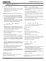
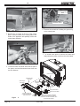
t rt G de
Note: 7KHVHDUHJHQHULFGUDZLQJVDQGPD\QRWUHSUHVHQW
\RXUVSHFL¿FPRGHO
FIRST FIRE ITEMS NEEDED:
LOW
ADD NEW
OAD WOOD
O EN AIR
ON RO
HIGH
10 Pieces of Newspaper, 10-20 Pieces of Dry Kindling
and a Few Pieces of Dry Split Wood.
A ER
BURN
RATE
Upper
right
corner
START-UP
AIR
Lower
right
corner
Push In and then Pull Out
ADD
2
1
IND ING
3
WARNING R s O
re
DO NOT LEAVE UNATTENDED
During startup, if additional draft is needed,
allow the door to remain open approximately1/2 inch. Once the draft is established,
close and securely latch the door to prevent
6SLOODJHRIVPRNHÀDPHDQGFDUERQ
monoxide
6SLOODJHRIVSDUNVFRDOVDQGORJV
2YHU¿ULQJ
IG
E A ER
DO NO
tended
4
ADD ORE WOOD
E URE Y A
E DOOR
e e t e sto e n t
t t e door o en
5
REDU E AIR
ON RO
Set to desired heat
output
HIGH
LOW
The stove is ready for
normal operation.
BURN RATE CONTROL
Upper Right Corner
6
Page 16
7
7075-166C
May 23, 2013
R
VOYAGEUR GRAND Wood Insert
nten n e nd er
A D s os
e
o As es
FreTuency: When ash reaches the top of the brick
FRYHUV VKRXOG QRW VSLOO RYHU FRYHUV /HDYH LQFK
PPRIDVKLQWKHERWWRPRIWKHILUHER[
By: Homeowner
WARNING! Risk of Fire! $VKHVFRXOGFRQWDLQKRWHPEHUV
3ODFHDVKHVLQDPHWDOFRQWDLQHUZLWKDWLJKW¿WWLQJOLG
7KHFORVHGFRQWDLQHUVKRXOGEHSODFHGRQDQRQFRPEXVWLEOH
ÀRRU RU RQ WKH JURXQG ZHOO DZD\ IURP DOO FRPEXVWLEOH
PDWHULDOVSHQGLQJ¿QDOGLVSRVDO
,IWKHDVKHVDUHGLVSRVHGRIE\EXULDOLQVRLORURWKHUZLVH
locally dispersed, they should be retained in the closed
container until all cinders have thoroughly cooled
ne nd
ne
Ins e t on e n n
reosote
or t on nd Need or Re o
When wood is burned slowly, it produces tar and other
organic vapors, which combine with expelled moisture
to form creosote.
The creosote vapors condense in the relatively cool
FKLPQH\ÀXHRIDVORZEXUQLQJ¿UH
$VDUHVXOWFUHRVRWHUHVLGXHDFFXPXODWHVRQWKHÀXH
lining. When ignited this creosote makes an extremely
KRW¿UH
The chimney and chimney connector shall be inspected
every two months during the heating season to determine
when a creosote buildup has occurred.
When creosote has accumulated it shall be removed to
UHGXFHWKHULVNRIDFKLPQH\¿UH
A
onne tor
FreTuency: Every 2 months during heating season or
DV UHFRPPHQGHG E\ D FHUWL¿HG FKLPQH\ VZHHS PRUH
IUHTXHQWO\LIFKLPQH\H[FHHGVRULVXQGHUIHHW
WRPPHDVXUHGIURPERWWRPRIDSSOLDQFH
By: &HUWL¿HGFKLPQH\VZHHS
5HPRYH DOO DVK IURP WKH ¿UHER[ DQG H[WLQJXLVK DOO KRW
embers before disposal.
n e Ins e t on Ro t ne
re en
Every 2 months at the same time the chimney and chimney connector are inspected.
By: Homeowner
Check for
&UDFNVLQJODVV
'RRUKDQGOHVPRRWKFDPRSHUDWLRQ
%DIÀHDQGFHUDPLFEODQNHWFRUUHFWSODFHPHQW
$OORZWKHDSSOLDQFHWRFRROFRPSOHWHO\
%DIÀHIRUZDUSDJH
If your type of installation involves a full reline of the
FKLPQH\LWZLOOEHQHFHVVDU\WRHLWKHUUHPRYHWKHEDIÀH
IURP WKH LQVHUW RU UHPRYH WKH LQVHUW IURP WKH ¿UHSODFH
and disconnect the vent prior to cleaning the chimney.
Refer to
e
LQWKLVPDQXDOIRULQVWUXFWLRQVRQ%DIÀH
Removal.
)LUHEULFNIRUFUDFNVEURNHQRUFUXPEO\
If your type of installation is direct connect within a masonry
chimney, the insert will need to be pulled out from the
¿UHSODFHDQGGLVFRQQHFWHGIURPWKHÀXHSULRUWRFOHDQLQJ
the chimney.
The creosote or soot should be removed with a brush
VSHFL¿FDOO\GHVLJQHGIRUWKHW\SHRIFKLPQH\LQXVH
&OHDQRXWIDOOHQDVKHVIURPWKH¿UHER[
It is also recommended that before each heating season
the entire system be professionally inspected, cleaned
and repaired if necessary.
*ODVVIUDPHIRUORRVHVFUHZV
D
e nn
ted
FreTuency: $VGHVLUHG
By: Homeowner
r
es
&OHDQ DOO WKH ¿QJHUSULQWV DQG RLOV IURP SODWHG VXUIDFHV
E ORE ¿ULQJWKHDSSOLDQFHIRUWKH¿UVWWLPH
,IQRWFOHDQHGSURSHUO\EHIRUHOLJKWLQJ\RXU¿UVW¿UHWKH
oils can cause permanent markings on the plating.
$IWHUWKHSODWLQJLVFXUHGWKHRLOVZLOOQRWDIIHFWWKH¿QLVK
and little maintenance is required.
Wipe clean as needed.
WARNING! Risk of Fire!
'RQRWXVHFKLPQH\FOHDQHUVRUÀDPHFRORUDQWVLQ\RXU
DSSOLDQFH,WZLOOFRUURGH\RXUSLSH
May 23, 2013
'RRUJDVNHW'ROODUELOOWHVW3ODFHDGROODUELOOEHWZHHQ
the stove and the door and then shut the door. If you can
pull the dollar bill out, replace the door gasket.
CAUTION! Do not use polishes with abrasives. ,W ZLOO
VFUDWFKSODWHGVXUIDFHV
7075-166C
Page 17
R
VOYAGEUR GRAND Wood Insert
E G ss
Ins e t re r
Instr t ons
e nn
FreTuency: $VGHVLUHG
By: Homeowner
&OHDQJODVVZLWKDQRQDEUDVLYHJODVVFOHDQHU$EUDVLYH
cleaners may scratch and cause glass to crack.
If the deposits on the glass are not very heavy, normal
glass cleaners work well. Heavier deposits may be
removed by using a damp cloth dipped in wood ashes or
by using a commercially available oven cleaner.
$IWHUXVLQJDQRYHQFOHDQHULWLVDGYLVDEOHWRUHPRYHDQ\
residue with a glass cleaner or soap and water. Oven
FOHDQHU OHIW RQ GXULQJ WKH QH[W ¿ULQJ FDQ SHUPDQHQWO\
VWDLQ WKH JODVV DQG GDPDJH WKH ¿QLVK RQ SODWHG PHWDO
surfaces.
$SRUWLRQRIWKHFRPEXVWLRQDLUHQWHULQJWKH¿UHER[LVGHÀHFWHGGRZQRYHUWKHLQVLGHRIWKHGRRUJODVV
7KLVDLUÀRZ³ZDVKHV´WKHJODVVKHOSLQJWRNHHSVPRNH
from adhering to its surface.
:KHQRSHUDWHGDWDORZEXUQUDWHOHVVDLUZLOOEHÀRZLQJ
over the glass and the smoky, relatively cool condition of
DORZ¿UHZLOOFDXVHWKHJODVVWREHFRPHFRDWHG
Re
e ent
FreTuency: $IWHUHDFKDVKUHPRYDO
By: Homeowner
5HSODFHWKH¿UHEULFNLIWKH\EHFRPHFUXPEO\DQGRULI
WKHUHLVDLQFKPPJDSEHWZHHQWKHEULFNV
7KH¿UHER[LVOLQHGZLWK¿UHEULFNZKLFKKDVH[FHSWLRQDO
LQVXODWLQJSURSHUWLHV'RQRWXVHDJUDWHVLPSO\EXLOG
D¿UHRQWKH¿UHER[ÀRRU'RQRWRSHUDWHDSSOLDQFH
ZLWKRXW¿UHEULFN
$IWHUWKHFRDOVKDYHFRPSOHWHO\FRROHGUHPRYHDOO
ROGEULFNDQGDVKIURPXQLWDQGYDFXXP¿UHER[
2. Remove new brick set from box and lay out to the
diagram shown in the instructions that come with
the replacement brick set.
3. Lay bottom bricks in unit.
4. Install rear bricks on the top of the bottom bricks.
5. Install side bricks. Slide top of brick under clips
RQVLGHRI¿UHER[DQGSXVKWKHERWWRPRIWKHEULFN
XQWLOLWLVÀXVKZLWKWKHVLGHRIWKHXQLW
2SHUDWLQJ WKH DSSOLDQFH ZLWK WKH %XUQ 5DWH$LU &RQWURO
DQG6WDUW8S$LU&RQWURODOOWKHZD\RSHQIRUPLQutes should remove the built up coating.
CAUTION! Handle glass assembly with care. Glass is
breakable.
se Part 832-0550 when ordering individual brick. Provide
brick dimension or copy the page in the service parts list, mark
the desired brick and take it to your authorized dealer.
$YRLGVWULNLQJVFUDWFKLQJRUVODPPLQJJODVV
$YRLGDEUDVLYHFOHDQHUV
'RQRWFOHDQJODVVZKLOHLWLVKRW
Page 18
7075-166C
May 23, 2013
R
VOYAGEUR GRAND Wood Insert
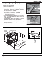
G
Re eren e
nten n e G de
CAUTION! A o t e
do n e ore er or
n
n
n e to o
ete
oo
e n n or
nten n e
%DIÀH%ODQNHW
Blanket
Baffle
Optional Blower
Chimney System
6WDUWWKH¿UVWLQVSHFWLRQDIWHUWKH¿UVWPRQWKVRIXVH
RU LI SHUIRUPDQFH FKDQJHV DQG DGMXVW \RXU VFKHGXOH
accordingly. Maintenance is required for safe operation
and must be performed to maintain your warranty.
Frequency
0217+/<
or
$IWHU(YHU\
Cord of Wood
<($5/<
or
$IWHU(YHU\
4 Cords of
Wood
(9(5<
MONTHS
or
$IWHU(YHU\
4 Cords of
Wood
Task
%DIÀHDQGEODQNHWSODFHPHQWLVFULWLFDOWR
KHDWRXWSXWHI¿FLHQF\DQGRYHUDOOOLIHRIWKH
XQLW0DNHVXUHWKHEDIÀHLVSXVKHGDOORIWKH
ZD\WRWKHEDFNRIWKH¿UHER[DQGWKHEODQNHW
LVOD\LQJÀDW,QVSHFWEDIÀHIRUFUDFNV
acuum the blower impellers.
The chimney and chimney cap must be inspected for soot and creosote every two
months during the burn season or more frequency if chimney exceeds or is under 14-16 ft
PPPHDVXUHGIURPERWWRPRIDSSOLance.
This will prevent pipe blockage, poor draft,
DQGFKLPQH\¿UHV
$OZD\VEXUQGU\ZRRGWRKHOSSUHYHQWFDS
blockage and creosote build-up.
)LUHEULFN$VK5HPRYDO
:((./<
or
$IWHU(YHU\
25 Loads of
Wood
'RRU*ODVV$VVHPEOLHV
Door Handle
Latch Cam
Spacing Washers
:((./<
or
$IWHU(YHU\
25 Loads of
Wood
:((./<
or
$IWHU(YHU\
Loads of Wood
$VKHVPXVWEHFRROEHIRUH\RXFDQGLVSRVH
of the ashes in a non-combustible container.
)LUHEULFNLVGHVLJQHGWRSURWHFW\RXU¿UHER[
$IWHUDVKHVDUHUHPRYHGLQVSHFWWKH¿UHEULFNDQGUHSODFH¿UHEULFNVWKDWDUHFUXPbling, cracked or broken.
Keep door and glass gasket in good shape to
maintain good burn times on a low burn setting.
To test place a dollar bill between the stove
and door and then shut the door. If you can
pull the dollar out, remove one washer from
door handle behind latch cam and try again. If
you can still pull it out, replace the door gasket.
Check the glass frame for loose screws to
prevent air leakage. Check glass for cracks.
&KHFNWKHGRRUODWFKIRUSURSHUDGMXVWPHQW
This is very important especially after the door
rope has formed to the stove face.
Check door handle for smooth cam operation.
Note: 7KHVHDUHJHQHULFGUDZLQJVDQGPD\QRWUHSUHVHQW\RXUVSHFL¿FPRGHO
May 23, 2013
7075-166C
Page 19
R
VOYAGEUR GRAND Wood Insert
ro
es oot n G de
With proper installation, operation, and maintenance your woodstove will provide years of trouble-free service. If you do
H[SHULHQFHDSUREOHPWKLVWURXEOHVKRRWLQJJXLGHZLOODVVLVW\RXRUDTXDOL¿HGVHUYLFHSHUVRQLQWKHGLDJQRVLVRIDSUREOHP
and the corrective action to be taken.
t rt
re ro e s
&DQQRWJHW¿UHVWDUWHG
Excessive smoke or spillage
Burns too slowly
Not enough heat output
oss
e
se
o t on
Not enough kindling/paper or no
kindling/paper
8VHGU\NLQGOLQJPRUHSDSHU$UUDQJHNLQGOLQJ
wood for air movement.
Check for restricted termination cap
&KHFNIRUEORFNDJHRIRXWVLGHDLUNLWLILQVWDOOHG
&KHFNIRUÀXHEORFNDJH
1RWHQRXJKDLUIRU¿UHWRLJQLWH
3UHZDUPÀXHEHIRUHVWDUWLQJ¿UHUHIHUWR%XLOGLQJ
D)LUH6HFWLRQ
&KHFNIRUDGHTXDWHYHQWKHLJKWUHIHUWR&KLPQH\
+HLJKW6HFWLRQ
Open window below the appliance towards the
wind.
Wood condition is too wet, too
large
8VHGU\VHDVRQHGZRRGUHIHUWR6HDVRQHG:RRG
6HFWLRQ
Bed of coals not established
before adding wood
Start with paper & kindling to establish bed of
FRDOVUHIHUWR%XLOGLQJD)LUH6HFWLRQ
Flue blockage such as birds
nests or leaves in termination
cap
Have chimney inspected for creosote and cleaned
E\DFHUWL¿HGFKLPQH\VZHHS
Down draft or negative pressure
Competition with exhaust
devices
'RQRWXVHH[KDXVWIDQVGXULQJVWDUWXSUHIHUWR
1HJDWLYH3UHVVXUH6HFWLRQ
Fire burns too fast
Mix in hardwood.
Extremely dry or soft wood
0L[LQOHVVVHDVRQHGZRRGDIWHU¿UHLVHVWDEOLVKHG
UHIHUWR:RRG)XHO6HFWLRQ
&KHFNIRUFRUUHFWYHQWKHLJKWWRRPXFKYHUWLFDO
height creates overdrafting.
Overdrafting
Page 20
Open window below the appliance towards the
wind.
&KHFNORFDWLRQRIYHQWWHUPLQDWLRQUHIHUWR
&KLPQH\7HUPLQDWLRQ5HTXLUHPHQW6HFWLRQ
7075-166C
May 23, 2013
R
VOYAGEUR GRAND Wood Insert
er
e
rts Re
e ent
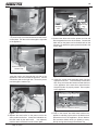
UN
A G ss Re
UG A
I E RO ANY OWER OUR E
E ORE RE A ING ANY O
ONEN
e ent
n
D s Re
e ent
ont d
(Replace with 5mm ceramic glass only)
2. Remove the 2 screws from the blower access assembly
1. (QVXUHWKDWWKH¿UHLVRXWDQGWKHDSSOLDQFHLVFRROWR
and slide assembly away from the appliance
the touch.
3. Locate the snap disc bracket assembly behind the blower
2. Protect a table or counter top with padding or towels.
controls on the right side under the ash lip.
re
3URWHFW\RXUKDQGVDQGZHDUJORYHVWRSUHYHQWLQMXU\
4. Remove the 2 mounting screws in the blower control
3. Remove the door with the broken glass by lifting the
bracket and slide assembly towards you.
door up and off of the hinges.
5. sing a Phillips head screw driver, remove the 2 screws
4. Lay door face down on a table or counter making sure
from the snap disc and lift the snap disc off of the mounting
WKHKDQGOHKDQJVRYHUWKHHGJHVRWKHGRRUOD\VÀDWRQ
bracket. Disconect the wires and replace with new snap
a soft surface.
disc and re-connect the wires.
5. Remove the screws from each glass retainer and remove
6. Slide the blower control bracket back into position and
WKHJODVV,IVFUHZVDUHGLI¿FXOWWRUHPRYHVRDNZLWK
secure with the 2 mounting screws.
SHQHWUDWLQJRLO¿UVW
6.
Center the glass with edges evenly overlapping the
RSHQLQJLQWKHGRRULHVDPHVSDFHWRSDQGERWWRP
OHIWDQGULJKWVLGHV
7.
Replace the glass retainers. Be careful not to cross
thread the screws.
Blower Controls & Snap
Disc Under Ash Lip
8. 7LJKWHQ HDFK UHWDLQHU MXVW D IHZ WXUQV XQWLO HDFK LV
secured. Check again for centering of glass in door
frame. Continue to tighten each retainer alternately, a
few turns at a time, until the glass is secure. DO NOT
O ERTIGHTEN - can cause glass to break.
Snap Disc
9.
Replace the door on the appliance.
WARNING! Risk of Fire or Injury!
8VHRQO\JODVVWKDWLVVSHFL¿HGLQWKHPDQXDO'2127
UHSODFHZLWKDQ\RWKHUPDWHULDO*ODVVEUHDNDJHZLOORFFXU
re
n
Ds
o
t on
CAUTION!
Wrn D
+DQGOHJODVVZLWKFDUH
,QVSHFWWKHJDVNHWWRHQVXUHLWLVXQGDPDJHG
'R127VWULNHVODPRUVFUDWFKJODVV
'R127RSHUDWHDSSOLDQFHZLWKJODVVGRRUDVVHPEO\
UHPRYHG
'R127RSHUDWHZLWKJODVVFUDFNHGEURNHQRU
VFUDWFKHG
Quadra-Fire appliances are equipped with ceramic super
heat-resistant glass, which can only be broken by impact or
misuse.
r
Blower
Black
White
White
Snap Disc
Power Cord
Black
n
D s Re
White
Black
e ent
1. The grille on the blower access assembly is hinged. Swing
the grille downward to expose the 2 screws.
re
on
e
Switch
Rheostat
re
May 23, 2013
7075-166C
Page 21
R
VOYAGEUR GRAND Wood Insert
D
o er Re
e ent
AU ION
1. The grille on the blower access assembly is hinged.
Swing the grille downward to expose the 2 screws.
re
o Rs .
'R127UHPRYHJURXQGLQJSURQJIURPSOXJ
3OXJGLUHFWO\LQWRSURSHUO\JURXQGHGSURQJ
receptacle.
5RXWHFRUGDZD\IURPDSSOLDQFH
Do NOT route cord under or in front of appliance.
2. Remove the 2 screws from the blower access assembly
and slide assembly away from the appliance.
3. Disconnect the wires from the blower.
4. Remove the 2 screws from the hold down bracket and
pull the blower and bracket forward.
WARNING
5. Remove the blower from the hold down bracket.
6. Remove the protection guards from each end of the
blower.
7. Re-install in reverse order. Be certain that the hold down
bracket s screws are completely seated in the gromments. Insert the locating tab in the hold down bracket
into the placement slot.
re R s
'R127DOORZKRWFRDOVRUHPEHUVWRRYHUÀRZDVKOLS
May melt protective wire coating on fan power
FRUGFDXVLQJHOHFWULFDOVKRUW¿UHRULQMXU\
CAUTION! Unplug appliance
from power source before
replacing any components.
Placement Slot
Blower Access
Assembly
Grille hinges
downward
Remove Screws &
Pull Access Assembly
away from Insert
Hold Down
Bracket
Remove Screws from Hold
Down Bracket and Pull
Forward
re
Page 22
7075-166C
May 23, 2013
R
VOYAGEUR GRAND Wood Insert
E Door
F BafÀe Ceramic BlanNet Removal
nd e Asse
1. Install washer on door handle shaft.
5HPRYH DOO DVK IURP WKH ¿UHER[ DQG H[WLQJXLVK DOO KRW
embers before disposal into a metal container.
2. Slide door handle through door.
,W LV HDVLHU WR UHPRYH ERWK EDIÀH ERDUGV DQG FHUDPLF
blanket after the tube channel assembly has been partially
4. Install key in groove.
disassembled and the right side lowered. Follow steps
$OLJQJURRYHLQODWFKFDPZLWKNH\VOLGHODWFKFDPRYHU
1 through 4 on
e
for removal of the tube channel
shaft
assembly. It is not necessary to completely remove the
tube channel assembly.
6. Install locknut but do not overtighten, the handle needs
to move smoothly.
2QFHWKHEDIÀHSURWHFWLRQFRYHUKDVEHHQUHPRYHGSXOO
WKHEDIÀHERDUGVDQGFHUDPLFEODQNHWIRUZDUGDERXWLQFK
7. Install handle turning in a counter-clockwise motion to
PPDQGWKHQRYHUODSWKHEDIÀHVDERXWLQFKHV
desired location on door handle rod.
re
PP
re
.
,QVWDOODGGLWLRQDOZDVKHUVDVVKRZQLQ
re
CAUTION!'RQRWRYHUWLJKWHQORFNQXW7KHGRRUKDQGOH
QHHGVWRPRYHVPRRWKO\
Latch Cam
4. Slide the tube channel assembly to the left as far as it will
JRDQGORZHUWKHULJKWVLGH5HPRYHWKHEDIÀHERDUGVDQG
ceramic blanket together.
re
.
5HLQVWDOOLQUHYHUVHRUGHU%HVXUHWKHEDIÀHERDUGVDQG
ceramic blanket are in their proper positions. ee
re
on
e
Door Cross
Section
Door Handle Shaft
Ceramic Blanket
Locknut
Spacing
Washers
Baffle Boards Overlapping
Square Key
Fiber Handle
re
Figure 23.2
Slide Tube Channel to the
Left and Lower Right Side
Figure 23.3
May 23, 2013
7075-166C
Page 23
R
er
.
u e
e
e
e
e e
5HPRYLQJ7XEH&KDQQHO$VVHPEO\
Bend Back Tabs
1. Remove the 3 right side bricks.
5HPRYHWKHEDIÀHSURWHFWLRQFKDQQHOE\EHQGLQJEDFNWKHWDEV
using needle nose pliers located at the right and left side of the
protection cover. Lift the cover up slightly and pull toward the
IURQWDQGRXWRIWKH¿UHER[Figure 2 . .
Baffle Protection
Channel
3. Locate the 2 channel nuts and two bolts inside of chamber and
remove using a 7/16 socket wrench. Figure 2 .2.
Figure 2 .
: Soak the bolts with penetrating oil for at least 15 minutes
before trying to remove them.
4. Slide the tube channel assembly all the way to left until it is off the
threads. Drop the right side down, then slide the assembly back
to right. Figure 2 .3.
7KHFHUDPLFEODQNHWDQGERWKEDIÀHERDUGVFDQEHUHPRYHGDW
the same time you remove the tube channel assembly.
6. When the tube channel assembly is free of the left side supSRUWURWDWHFORFNZLVHDQGSXOODVVHPEO\EODQNHWDQGEDIÀHVRXW
through the front opening.
Use 7/16 Socket Wrench
and Remove Channel Nuts
7. Re-install in reverse order.
Tube
Channel
Assembly
Figure 2 .2
2 Tube Channel Nuts
Ceramic Blanket
2 Baffle Boards
Baffle
Protection Channel
Figure 2 .3
Page 24
7075-166C
May 23, 2013
R
er
er
e i g
ui e
re
. e ig
i
i er i
. r
Draft is the pressure difference needed to vent appliances
successfully. When a appliance is drafting successfully, all
combustion byproducts are e iting the home through the
chimney.
Check building codes prior to installation.
,QVWDOODWLRQ 0867 FRPSO\ ZLWK ORFDO UHJLRQDO VWDWH DQG
national codes and regulations.
&RQVXOW LQVXUDQFH FDUULHU ORFDO EXLOGLQJ ¿UH RI¿FLDOV RU
DXWKRULWLHVKDYLQJMXULVGLFWLRQDERXWUHVWULFWLRQVLQVWDOODWLRQ
inspection, and permits.
uadra- ire wood inserts are designed for factory-built nonFRPEXVWLEOH ¿UHSODFHV WKDW KDYH EHHQ LQVWDOOHG LQ DFFRUdance with the ational, Provincial, State and local building
codes.
1. Prior to installing the wood insert:
Considerations for successful draft include:
3UHYHQWLQJQHJDWLYHSUHVVXUH
/RFDWLRQRIDSSOLDQFHDQGFKLPQH\
o be sure that your appliance burns properly:
'XULQJDORZEXUQWKHFKLPQH\GUDIWVWDWLFSUHVVXUHVKRXOG
EHDSSUR[LPDWHO\LQFKZDWHUFROXPQ:&
'XULQJDKLJKEXUQWKHFKLPQH\GUDIWVKRXOGEHDSSUR[LPDWHO\
LQFK:&
0HDVXUHWKH:&DWLQFKHVPPDERYHWKHWRSRIWKH
appliance after one hour of operation at each burn setting.
earth
ome echnologies assumes no
+DYHWKHFKLPQH\DQGDGMDFHQWVWUXFWXUHLQVSHFWHGDQG
responsibility
for
the
improper
performance of the appliance
FOHDQHGE\TXDOL¿HGSURIHVVLRQDOV+HDUW+RPH7HFKsystem
caused
by:
QRORJLHVUHFRPPHQGVWKDW1),RU&6,$FHUWL¿HGSURIHVVLRQDOV RU WHFKQLFLDQV XQGHU WKH GLUHFWLRQ RI FHUWL¿HG
nade uate draft due to environmental conditions
SURIHVVLRQDOVFRQGXFWDPLQPXPRID1)3$/HYHO
inspection of the chimney.
'RZQGUDIWV
7LJKWVHDOLQJFRQVWUXFWLRQRIWKHVWUXFWXUH
5HSODFH FRPSRQHQW SDUWV RI WKH FKLPQH\ DQG ¿UHSODFH
DVVSHFL¿HGE\WKHSURIHVVLRQDOV
0HFKDQLFDOH[KDXVWLQJGHYLFHV
2YHUGUDIWLQJFDXVHGE\H[FHVVLYHFKLPQH\KHLJKWV
(QVXUHDOOMRLQWVDUHSURSHUO\HQJDJHGDQGWKHFKLPQH\LV
,GHDOSHUIRUPDQFHLVZLWKKHLJKWRIFKLPQH\EHWZHHQ
properly secured.
IHHWPPHDVXUHGIURPWKHEDVHRI
2. Prior to installing, determine the following:
the appliance.
7\SHRIFKLPQH\FRQQHFWRUWREHXVHG
VLQJOHZDOOLQFKPPGLDPHWHUVWDLQOHVVVWHHO
or
double wall, LQFKPPGLDPHWHUVWDLQOHVVVWHHO
Fire i .
&RQVXOW ge 3
32 for clearances to combustibles
earth
ome echnologies disclaims any
3RZHURXWOHWORFDWHGFORVHE\IRURSWLRQDOEORZHU
responsibility for, and the warranty will be
i i
i
.
'2127&211(&77+,681,772$&+,01(<
)/8(6(59,&,1*$127+(5$33/,$1&(
'2127&211(&772$1<$,5',675,%87,21
'8&7256<67(0
0D\DOORZÀXHJDVHVWRHQWHUWKHKRXVH
May 23, 2013
voided by, the following actions:
,QVWDOODWLRQDQGXVHRIDQ\GDPDJHGDSSOLDQFH
0RGL¿FDWLRQRIWKHDSSOLDQFH
,QVWDOODWLRQ RWKHU WKDQ DV LQVWUXFWHG E\ +HDUWK +RPH
echnologies.
,QVWDOODWLRQDQGRUXVHRIDQ\FRPSRQHQWSDUWQRWDSSURYHG
by earth
ome echnologies.
2SHUDWLQJ DSSOLDQFH ZLWKRXW IXOO\ DVVHPEOLQJ DOO
components.
2SHUDWLQJDSSOLDQFHZLWKRXWOHJVDWWDFKHGLIVXSSOLHGZLWK
XQLW
'R1272YHU¿UH,IDSSOLDQFHRUFKLPQH\FRQQHFWRUJORZV
\RXDUHRYHU¿ULQJ
Any such action that may cause a ¿re ha]ard.
7075-166C
Page 25
R
er
.
eg i e re
ure
i i
i
.
1HJDWLYHSUHVVXUHFDQFDXVHVSLOODJHRIFRPbustion fumes, soot and carbon mono ide.
$SSOLDQFHQHHGVWRGUDIWSURSHUO\IRUVDIHW\
egative pressure results from the imbalance of air available
for the appliance to operate properly. t can be strongest in
lower levels of the house.
Causes include:
([KDXVWIDQVNLWFKHQEDWKHWF
5DQJHKRRGV
&RPEXVWLRQDLUUHTXLUHPHQWVIRUIXUQDFHVZDWHUKHDWHUV
and other combustion appliances
&ORWKHVGU\HUV
/RFDWLRQRIUHWXUQDLUYHQWVWRIXUQDFHRUDLUFRQGLWLRQLQJ
,PEDODQFHVRIWKH+9$&DLUKDQGOLQJV\VWHP
8SSHUOHYHODLUOHDNVVXFKDV
- Recessed lighting
$WWLFKDWFK
- Duct leaks
o minimi e the effects of negative air pressure:
,QVWDOOWKHRXWVLGHDLUNLWZLWKWKHLQWDNHIDFLQJSUHYDLOLQJ
winds during the heating season
(QVXUHDGHTXDWHRXWGRRUDLUIRUall combustion appliances
and e haust e uipment
(QVXUHIXUQDFHDQGDLUFRQGLWLRQLQJUHWXUQYHQWVDUHQRW
located in the immediate vicinity of the appliance
$YRLG LQVWDOOLQJ WKH DSSOLDQFH QHDU GRRUV ZDONZD\V RU
small isolated spaces
5HFHVVHGOLJKWLQJVKRXOGEHD³VHDOHGFDQ´GHVLJQ
$WWLFKDWFKHVZHDWKHUVWULSSHGRUVHDOHG
$WWLFPRXQWHGGXFWZRUNDQGDLUKDQGOHUMRLQWVDQGVHDPV
taped or sealed
%DVHPHQWLQVWDOODWLRQVVKRXOGEHDYRLGHG
Page 26
7075-166C
May 23, 2013
R
er
.
i g
ur
e
i
e
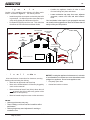
Location of the appliance and chimney will affect perforPDQFH$VVKRZQLQFigure 2 . the chimney should:
,QVWDOOWKURXJKWKHZDUPVSDFHHQFORVHGE\WKHEXLOGing envelope. his helps to produce more draft, espeFLDOO\GXULQJOLJKWLQJDQGGLHGRZQRIWKH¿UH
3HQHWUDWHWKHKLJKHVWSDUWRIWKHURRI7KLVPLQLPL]HV
the affects of wind turbulence and down drafts.
Recommended
Location
&RQVLGHU WKH DSSOLDQFH ORFDWLRQ LQ RUGHU WR DYRLG
ÀRRUDQGFHLOLQJDWWLFMRLVWVDQGUDIWHUV
/RFDWH WHUPLQDWLRQ FDS DZD\ IURP WUHHV DGMDFHQW
structures, uneven roof lines and other obstructions.
<RXUORFDOGHDOHULVWKHH[SHUWLQ\RXUJHRJUDSKLFDUHDDQG
can usually make suggestions or discover solutions that will
HDVLO\FRUUHFW\RXUÀXHSUREOHP
Recommended
Location
Marginal
Location
Location
Not
Recommended
Location NOT
Recommended
Windward
Outside Termination Cap
Leeward
Multi-level Roofs
Figure 2 .
.
i
e
er i
i
e uire e
ollow manufacturer s instructions for clearance, securing
ÀDVKLQJDQGWHUPLQDWLQJWKHFKLPQH\
Must have an approved and Listed cap
Must not be located where it will become plugged by
snow or other material
0XVWWHUPLQDWHDWOHDVWIHHWFPDERYHWKHURRI
DWOHDVWIHHWFPDERYHDQ\SRUWLRQRIWKH
URRIZLWKLQIHHWFP
0XVWEHORFDWHGDZD\IURPWUHHVRURWKHUVWUXFWXUHV
NOTICE: /RFDWLQJWKHDSSOLDQFHLQDEDVHPHQWRULQDORFDWLRQ
RIFRQVLGHUDEOHDLUPRYHPHQWFDQFDXVHLQWHUPLWWHQWVPRNH
VSLOODJHIURPDSSOLDQFH'RQRWORFDWHDSSOLDQFHQHDU
)UHTXHQWO\RSHQGRRUV
&HQWUDOKHDWRXWOHWVRUUHWXUQV
NOTICE
&KLPQH\SHUIRUPDQFHPD\YDU\
7UHHVEXLOGLQJVURRIOLQHVDQGZLQGFRQGLWLRQVDIIHFW
SHUIRUPDQFH
&KLPQH\KHLJKWPD\QHHGDGMXVWPHQWLIVPRNLQJRU
RYHUGUDIWRFFXUV
May 23, 2013
7075-166C
Page 27
R
er
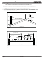
F. 2
3
ue
These are safety reTuirements and are not meant to assure proper Àue draft.
7KLVDSSOLDQFHLVPDGHZLWKDLQFKPPGLDPHWHUFKLPQH\FRQQHFWRUDVWKHÀXHFROODURQWKHXQLW
&KDQJLQJWKHGLDPHWHURIWKHFKLPQH\FDQDIIHFWGUDIWDQGFDXVHSRRUSHUIRUPDQFH
,WLVQRWUHFRPPHQGHGWRXVHRIIVHWVDQGHOERZVDWDOWLWXGHVDERYHIHHWDERYHVHDOHYHODQGRUZKHQ
WKHUHDUHRWKHUIDFWRUVWKDWDIIHFWÀXHGUDIW
Less than 10 ft. (305cm)
2 ft. (61cm)
2 ft. (61cm)
3 ft. (91cm)
Minimum
10 ft. (305cm) To Nearest Roofline
3 ft. (91cm)
Minimum
Pitched Roof
Figure 2 .
10 ft. (305cm) or more
Less than 10 ft. (305cm)
Wall or Parapet
2 ft. (61cm) Minimum
3 ft. (91cm) Minimum
3 ft. (91cm) Minimum
Flat Roof
Figure 2 .2
Page 2
7075-166C
May 23, 2013
R
er
.
u
ie
ee e
re
ur
e
i
efore beginning the installation be sure the following tools
and building supplies are available:
7/16 Socket
raming materia
1.
Reciprocating saw
igh temp caulking material l
3ODFHWKHDSSOLDQFHLQDORFDWLRQQHDUWKH¿QDO
installation area and follow the procedures below:
2.
Pliers
loves
pen the appliance and remove all the parts and
articles packed inside the Component Pack. nspect
all the parts and glass for shipping damage. Contact
your dealer if any irregularities are noticed.
3.
$OOVDIHW\ZDUQLQJVKDYHEHHQUHDGDQGIROORZHG
ammer
raming s uare
Phillips screwdriver
lectric drill and bits
lat blade screwdriver
Plumb line
Safety glasses
4.
his
ape measure
5.
loor protection re uirements have been met.
Level
Wire Cutters to remove from pallet
1/2-3/4 in. length, 6 or
self-drilling screws
Misc. screws and nails
. Fire
,QVWDOO DW OHDVW RQH VPRNH GHWHFWRU RQ HDFK ÀRRU RI
your home to ensure your safety.
hey should be
located away from the heating appliance and close
to the sleeping areas.
ollow the smoke detector
manufacturer s placement and installation instructions,
and be sure to maintain regularly.
.
6.
enting is properly installed per vent manufacturing
instructions.
7.
he proper clearances from the appliance and chimney to combustible materials have been met.
.
he masonry chimney is inspected by a professional
and is clean, or the factory built metal chimney is
installed according to the manufacturer s instructions and clearances.
.
he chimney meets the re uired minimum height.
e
7R SURYLGH UHDVRQDEOH ¿UH VDIHW\ WKH IROORZLQJ VKRXOG EH
given serious consideration:
10.
$OOODEHOVKDYHEHHQUHPRYHGIURPWKHJODVV
door.
11.
Plated surfaces have been wiped clean, if applicable.
12.
$ SRZHU RXWOHW LV DYDLODEOH QHDUE\ IRU XVH RI WKH
blower assembly.
$ FRQYHQLHQWO\ ORFDWHG &ODVV $ ILUH H[WLQJXLVKHU
to contend with small fires resulting from burning
embers.
e
i
e
e
5HPRYHDSSOLDQFHDQGFRPSRQHQWVIURPSDFNDJLQJDQG
inspect for damage.
9HQW V\VWHP FRPSRQHQWV DQG GRRUV DUH VKLSSHG LQ
separate packages.
5HSRUWWR\RXUGHDOHUDQ\SDUWVGDPDJHGLQVKLSPHQW
wner s Manual has been read.
Fire i .
nspect appliance and components for damage.
Damaged parts may impair safe operation.
'R127LQVWDOOGDPDJHGFRPSRQHQWV
'R127LQVWDOOLQFRPSOHWHFRPSRQHQWV
'R127LQVWDOOVXEVWLWXWHFRPSRQHQWV
Report damaged parts to dealer.
Read all the instructions before starting the
i
i . F
e e i
ru i
re u
uri g e i
i
e ure
i u
e
bene¿t.
May 23, 2013
7075-166C
Page 2
R
er
i e
.
i
i
e r
e i e
e
F ue
i
r i ei
i
2
i
32 5/8 (829mm)
23 3/4 (602mm)
e er
A
17 15/16
456 mm
B
5 (127mm)
Figure 3 .
ie
Figure 3 .2 Fr
er
14
(356mm)
ie
i
urr u
i e
Metal Surround w/Cast Trim-STD
42.5 in. (1080mm)
30 in. (762mm)
Metal Surround w/Cast Trim-LRG
48 in. (1219mm)
34 in. (864mm)
All Cast Surround
44 in. (1016mm)
33 in. (762mm)
Metal Surround w/Standard Trim-STD
43 in. (1092mm)
31 in. (787mm)
Metal Surround w/Standard Trim-LRG
51 in. (1295mm)
34 in. (2184mm)
25 3/4
(655mm)
14
(356mm)
11
(279mm)
4
(102mm)
15
(382mm)
30°
23 1/2
(597mm)
25 1/2
(648mm)
6 1/16
(154mm)
2 7/8
(73mm)
Figure 3 .
Figure 3 .3
Page 30
i e ie
i
i
F ue
i e ie
i
u
i
F ue
er
7075-166C
May 23, 2013
er
R
er
e r
e
u i e
ie
e
22 1/2
(572mm)
32 5/8
(829mm)
SIDE TRIM (3” max depth)
TOP TRIM (3/4” max depth)
SIDE WALL
43
(1092 mm)
HEARTH EXTENSION
(MINIMUM EMBER PROTECTION)
USA 38 1/4
CANADA 46 1/4
(1175mm)
MANTEL
(12” max depth)
USA 17 1/2
CANADA 19 1/2
(495mm)
45
(1143 mm)
MANTEL DEFLECTOR
REQUIRED
FIREPLACE FRONT SURFACE
.
HEARTH EXTENSION
(EMBER PROTECTION)
May 23, 2013
7075-166C
Page 31
R
er
.
e r
e
u i e
ie
e
.
Re
qu
ire
d
Pr
Su
ote
gg
cti
es
on
ted
Pr
ote
cti
on
NOTE: Keep Ashlip
Clear of Ashes
0 to 5 inches from bottom of unit, thermal protection required. R value of 2.38.
Figure 32.2
5 inches or more from bottom of
unit, ember protection only
required
Figure 32.
e r
ug
eu e i
ugge e
re
Fire i .
&RPSO\ZLWKDOOPLQLPXPFOHDUDQFHVWR
FRPEXVWLEOHVDVVSHFL¿HG
)DLOXUHWRFRPSO\PD\FDXVHKRXVH¿UH
e r
r
i i
Page 32
e
e
e regu
r
u
e re u e
e
ri
i g uri
7075-166C
May 23, 2013
R
er
.
u
i g
er
eF
r r e i
eri
er
u i i
ue
7KHNYDOXHLQGLFDWHVWKHDPRXQWRIKHDWLQ%78¶VWKDW
ZLOOÀRZLQKRXUWKURXJKVTXDUHIRRWRIDXQLIRUPPDWHULDOLQFKWKLFNIRUHDFKGHJUHH)RIWHPSHUDWXUHGLIIHUence from one side of the material to the other.
he L W R the k factor means less heat is being conducted through the non-combustible material to the combustible material beneath it.
he k value of a material must be e ual or smaller then the
re uired k value to be acceptable.
%78LQFK
IRRW2KRXUo)
er
e i
e
ue
he R value is a measure of a material s resisteance
to heat transfer.
R value is convenient when more than one material is
used since you can add the R values together, whereas you can not do this for k value.
he
R the R factor means less heat is being
conducted through the non-combustible material to
the combustible material beneath it.
he R value of a material must be e ual or larger then
the re uired R value to be acceptable.
er i g
Divide 1 by k and multiply the results times the thickness
in inches of the material.
R
1/k inches of thickness
er i g
Divide the inches of thickness by R.
k
inches of thickness/R
u
ample: loor protection re uires k value of 0. 4 and 3/4
inch thick.
$OWHUQDWLYH PDWHULDO KDV D N YDOXH RI DQG LV LQFK
thick.
Divide 0.6 by .75 k value of 0. 0. his k value is smaller
than 0. 4 and therefore is acceptable.
May 23, 2013
7075-166C
Page 33
R
er
i
.
e
e i g
i
e
e
.
e
e
e
0XVWKDYHDWOHDVWLQFKPP¿UHFOD\OLQLQJMRLQHG
with refractory cement.
i
i
i e
ee i er
re u e r
er r
e
i
u e e g
r u e e e i e re
e
i ue .
e :
he chimney can be new or e isting, masonry or
prefabricated and must meet the following minimum
UHTXLUHPHQWVDVVSHFL¿HGEHORZ
WARNING! Risk of Fire!
)ROORZ YHQWLQJ PDQXIDFWXUHU¶V FOHDUDQFHV DQG
LQVWUXFWLRQVZKHQLQVWDOOLQJYHQWLQJV\VWHP
.
i
0XVWPHHWPLQLPXPVWDQGDUGVRI1)3$
r
,W LV DOVR NQRZQ DV ÀXH SLSH RU VWRYH SLSH ,W PXVW EH
LQFKHV PP PLQLPXP GLDPHWHU VWDLQOHVV VWHHO
connector pipe.
i
r
e i
sting
i
chimneys should be inspected and cleaned by a
TXDOL¿HG SURIHVVLRQDO SULRU WR LQVWDOODWLRQ 7KH FKLPQH\
must not have cracks, loose mortar or other signs of deterioration and blockage. earth
ome recommends a
1),RU&6,$FHUWL¿HGSURIHVVLRQDORUDWHFKQLFLDQXQGHU
WKHGLUHFWLRQRIDFHUWL¿HGSURIHVVLRQDOFRQGXFWD/HYHO,,
LQVSHFWLRQSHU1)3$
ue
i
i
u
e
r e
re e
r u
he masonry wall of the chimney, if brick or modular
EORFNPXVWEHDPLQLPXPRILQFKHVPPQRPLQDO
thickness.
$ FKLPQH\ RI UXEEOH VWRQH PXVW EH DW OHDVW LQFKHV
PPWKLFN
&URVVVHFWLRQDO DUHD VKDOO FRQIRUP WR 1)3$ Section 12.4.5.1.
6KRXOG EH OLQHG ZLWK D LQFK PP VWDLQOHVV VWHHO
ÀXHOLQHUWRLPSURYHSHUIRUPDQFHDQGUHGXFHFUHRVRWH
EXLOGXSDQGGLI¿FXOW\VWDUWLQJD¿UH
$QHTXLYDOHQWOLQHUPXVWEHDOLVWHGFKLPQH\OLQHUV\VWHP
or other approved material.
1RGLOXWLRQDLULVDOORZHGWRHQWHUWKHFKLPQH\
1. 6HFXUHWKH¿UHSODFHGDPSHULQWKHRSHQSRVLWLRQ,I
this cannot be accomplished, it will be necessary to
remove the damper
ire Risk
nspection of Chimney:
&KLPQH\PXVWEHLQJRRGFRQGLWLRQ
0HHWVPLQLPXPVWDQGDUGRI1)3$
)DFWRU\EXLOWFKLPQH\PXVWEHLQFK
PP8/+7
2. Seal damper area of chimney around chimney
connector with a high temperature sealant or seal
LQVHUWDJDLQVWWKHIDFHRIWKH¿UHSODFH
3. oth methods must be removable and replaceable
for cleaning and re-installation.
:KHQ SRVVLEOH LQVWDOO DQ DLUWLJKW FOHDQRXW GRRU WR WKH
rear of the smoke shelf.
.
rger
i
e
earth
ome recommends that chimneys with larger
GLDPHWHUVWKDQLQFKHVPPEHIXOO\UHOLQHG$QRYHUVL]HGÀXHFDQDIIHFWGUDIWDQGLPSDLUSHUIRUPDQFHDQGZLOO
allow increased build-up of creosote which is why a full reline
is stongly recommended.
0DVRQU\FKLPQH\VDUHVLJQL¿FDQWO\OHVVWKDQLGHDO
IRUYHQWLQJVROLGIXHODSSOLDQFHV$PDVRQU\FKLPQH\LVQRW
VXEMHFWWRDQ\WHPSHUDWXUHOLPLWWHVWWKHUHIRUHDIXOOUHOLQH
is strongly recommended.
NOTICE: Check with your local building authorities
DQGRUFRQVXOWWKH1DWLRQDO)LUH3URWHFWLRQ$VVRFLDWLRQ
1)3$
Page 34
7075-166C
May 23, 2013
R
er
r
i
e
his insert conforms with the L 14 2 and LC S62
&DQDGD LQ DOO UHVSHFWV DQG LV DSSURYHG WR 8/ 8/&
VDIHW\ VWDQGDUGV IRU LQVWDOODWLRQ DQG XVH ZLWKLQ D ¿UHSODFH
ZLWKDPDVRQU\FKLPQH\LQDFFRUGDQFHZLWK1)3$DQG
&$1&6$%
In USA a minimum 5 foot length, 6 inch diameter Àue
i er i re uire
er
2
e er e r
e e
gie strongly re
e
u re i e
r
i u
er r
e.
,Q&DQDGDWKLV¿UHSODFHLQVHUWPXVWEHLQVWDOOHG
ZLWKDFRQWLQXRXVFKLPQH\OLQHURIDLQFKPPGLDPHWHUH[WHQGLQJIURPWKH¿UHSODFHLQVHUWWRWKHWKHWRSRIWKH
chimney.
he chimney liner must conform to the Class 3 re uirePHQWVRI&$18/&66WDQGDUGIRU/LQLQJ6\VWHPVIRU
sting
i
Masonry or actory- uilt Chimneys and ents,
RU&$18/&66WDQGDUGIRU/LQLQJ6\VWHPVIRU1HZ
Masonry Chimneys.
UL 1777 Insulated Stainless Steel
Liner or Other Approved Lining System
Follow Manufacturer’s
Instructions for Maximum
Liner Extension Above
Chimney
Follow Manufacturer’s Instructions
on Insulation and Support
Maximum 30 Degrees
Offset in Chimney
For Zero or Other Non-Code Clearances,
Follow Approved Liner Manufacturer’s Specific
Insulation Requirements: Different Clearances
May Require Different Specifications
Masonry Chimney Must
Have Structural Integrity
UL 1777 Insulated Stainless Steel
Liner or Other Approved Lining System
Minimum 8 in. (203mm) Masonry
Thickness in Front of Smoke Chamber
Damper Plate Removed or
Fastened in Open Position
Minimum Clearance in Accordance
with Insert Listing
Floor Protection in
Accordance with Insert
Listing
Seal with Non-Combustible Material
Combustible Floor
127(*HQHULFZRRGLQVHUWVKRZQQRWPRGHOVSHFL¿F
Figure 3 .
r
May 23, 2013
i
e
i
Fu
i er
i
e
7075-166C
3
uire e
er
Page 35
R
er
.
e
e
ir u
i g
Inches
r
his insert conforms with the safety standard L-14 2 and
8/&6&DQDGDLQDOOUHVSHFWVDQGLVDSSURYHGWR8/
8/&VDIHW\VWDQGDUGVIRULQVWDOODWLRQDQGXVHZLWKLQD¿UHSODFHZLWKPDVRQU\FKLPQH\LQDFFRUGDQFHZLWK1)3$
DQG&$1&6$%
F.
re
ri
e
e
i
e
he chimney can be new or e isting, masonry or prefabricated
and must meet the following minimum re uirements:
0XVW EH PLQLPXP LQFK PP LQVLGH GLDPHWHU RI
KLJKWHPSHUDWXUHFKLPQH\OLVWHGWR8/+7o)
or LC S62 .
0XVWXVHFRPSRQHQWVUHTXLUHGE\WKHPDQXIDFWXUHUIRU
installation.
0XVWPDLQWDLQFOHDUDQFHVUHTXLUHGE\WKHPDQXIDFWXUHU
for installation.
5HIHUWRPDQXIDFWXUHUVLQVWUXFWLRQVIRULQVWDOODWLRQ
7KLV LQVHUW LV OLVWHG WR 8/ 6WDQGDUG DQG LV
approved for installation into listed factory-built solid
fuel ¿UHSODFHVOLVWHGWR8/FRQIRUPLQJWRWKHIROORZLQJVSHFL¿FDWLRQVDQGLQVWUXFWLRQV
Minimum Width of Cavity Opening - Front
32-7/
35
Minimum Width of Cavity Opening - Rear
24
610
Minimum Height
24
610
Minimum Depth from Front to Rear
1
457
<RXZLOOQHHGWRDGGDGGLWLRQDOFOHDUDQFHVWRWKHVH
GLPHQVLRQVIRU\RXUVSHFL¿FLQVWDOODWLRQ$OVRDOORZVXI¿FLHQWFOHDUDQFHLI\RXDUHLQVWDOOLQJDQRXWVLGHDLUNLW
e er
i
e i er
u
urer r re
e
i
u
r i g e i er.
i
i
¿replaces without a permit will void the listing.
NOTICE: n Canada when using a factory-built chimney it must
be safety listed,
e
3
2
F
or conforming to
2
F
F
.
:$51,1*
ire Risk.
When lining air-cooled factory-built chimneys:.
5XQFKLPQH\OLQHUDSSURYHGWR8/7\SH
+7UHTXLUHPHQWVGHJUHHV)
5HLQVWDOORULJLQDOIDFWRU\EXLOWFKLPQH\FDS
21/<
'2127EORFNFRROLQJDLURSHQLQJVLQFKLPQH\
%ORFNLQJFRROLQJDLUZLOORYHUKHDWWKHFKLPQH\
7KH RULJLQDO IDFWRU\EXLOW FOHDUDQFH ¿UHSODFH FKLPQH\
cap must be re-installed after installing the approved
chimney liner meeting type L 103
re uirements
)SHU8/
7KH OLQHU PXVW EH VHFXUHO\ DWWDFKHG WR WKH LQVHUW ÀXH
collar and the chimney top.
7KH DLU ÀRZ RI WKH IDFWRU\EXLOW VROLG IXHO ¿UHSODFH
V\VWHPPXVWQRWEHDOWHUHG7KHÀXHOLQHUWRSVXSSRUW
DWWDFKPHQWPXVWQRWUHGXFHWKHDLUÀRZIRUWKHH[LVWLQJ
air-cooled chimney system.
1RGLOXWLRQDLULVDOORZHGWRHQWHUWKHFKLPQH\
1. 6HFXUHWKH¿UHSODFHGDPSHULQWKHRSHQSRVLWLRQ
f this cannot be accomplished, it will be necessary
to remove the damper.
2. Seal damper area of chimney around chimney
connector with a high temperature sealant or seal
LQVHUWDJDLQVWWKHIDFHRIWKH¿UHSODFH
7R PDLQWDLQ WKH IXQFWLRQDOLW\ RI WKH ¿UHSODFH¶V FKLPQH\
system you may use a Simpson Dura- ent DuraLiner
Slip anger, Part 4671, and attach to the bottom of the
¿UHSODFH FKLPQH\ FDS WR VXSSRUW WKH OLQHU <RX KDYH WZR
options to completing the installation.
i
e
re uire
u e i er
:
Re-attach the e isting top of the chimney cap.
i
i g i er
Re-attach the e isting top of the chimney cap and install a
new storm collar and a new liner cap.
3. oth methods must be removable and replaceable
for cleaning and re-installation.
Page 36
Millimeters
7075-166C
WARNING! Risk of Fire!
)ROORZ YHQWLQJ PDQXIDFWXUHU¶V FOHDUDQFHV DQG
LQVWUXFWLRQVZKHQLQVWDOOLQJYHQWLQJV\VWHP
May 23, 2013
R
er
.
e uri g
i
e
. F
e
$OO MRLQWV VKRXOG EH VHFXUHG ZLWK VKHHW PHWDO VFUHZV RU
rivets per pipe manufacturers instructions. he sections must
be attached to the insert and to each other with the crimped
PDOHHQGSRLQWLQJWRZDUGWKHLQVHUWFigure 3 . .
LINER CONNECTOR
r
ui
Fue Fire
e
$SHUPLWPD\EHUHTXLUHGIRULQVWDOODWLRQV¿QDODSSURYDOLV
FRQWLQJHQWRIWKHDXWKRULW\KDYLQJORFDOMXULVGLFWLRQConsult
LQVXUDQFHFDUULHUORFDOEXLOGLQJ¿UHRI¿FLDOVRUDXWKRULWLHV
KDYLQJ MXULVGLFWLRQ DERXW UHVWULFWLRQV LQVWDOODWLRQ LQVSHFtion, and permits.
,QVSHFWWKHH[LVWLQJ¿UHSODFHDQGFKLPQH\IRUDQ\GDPDJH
RUÀDZVVXFKDVEXUQRXWVPHWDORUUHIHFWRU\ZDUSLQJ
CRIMPED
END
TOWARDS
STOVE
FLUE
GAS
DIRECTION
,QVSHFWLRQ WR D PLQLPXP RI 1)3$ /HYHO ,, LV UHFRPPHQGHG $OO UHSDLUV PXVW EH PDGH SULRU WR LQVWDOOLQJ DQ
LQVHUW 7KH ¿UHSODFH PXVW EH VWUXFWXUDOO\ VRXQG DQG EH
able to support the weight of the solid-fuel insert
he factory-built chimney must be listed per L 127 or LC
610-M 7 for all installations. nstall thermal protection per
this appliance listing re uirements.
Figure 3 .
.
eri g
e Fire
e
7KH IROORZLQJ PRGL¿FDWLRQV RI IDFWRU\EXLOW ¿UHSODFHV DUH
permissible:
7KHIROORZLQJSDUWVPD\EHUHPRYHG
Damper
6PRNH6KHOIRU%DIÀH
mber Catches
iewing Screen/Curtain
ire
rate
Doors
7KH¿UHSODFHPXVWQRWEHDOWHUHGH[FHSWWKDWWKHGDPSHU
may be removed to accommodate a direct-connect starter
pipe or chimney liner,
ternal trim pieces which do not affect the operation
RIWKH¿UHSODFHPD\EHUHPRYHGSURYLGLQJWKH\FDQEH
VWRUHG RQ RU ZLWKLQ WKH ¿UHSODFH IRU UHDVVHPEO\ LI WKH
insert is removed.
he permanent metal warning label provided in the
component pack must be attached to the back of the
¿UHSODFHZLWKVFUHZVRUQDLOVVWDWLQJWKDWWKH¿UHSODFH
may have been altered to accommodate the insert,
and must be returned to original condition for use as a
FRQYHQWLRQDO¿UHSODFHFigure 3 .2.
0DQXIDFWXUHU GHVLJQHG DGMXVWDEOH VXSSRUW NLW FDQ EH
ordered from your dealer.
inal approval of this installation type is contingent upon
WKHDXWKRULW\KDYLQJMXULVGLFWLRQ
WARNING
u eig
i
i e er
i e
ee u eig
i e
i
e i er u
ei
e
ee i g
e
2
F re uire e
er
r
3
i
e r
e
r
.
e u i er
must be attached to the insert Àue collar and to the top
ee i i g i
e .
7KHÀXHOLQHUWRSVXSSRUWDWWDFKPHQWPXVWQRWUHGXFHWKH
DLU ÀRZ IRU WKH H[LVWLQJ DLUFRROHG FKLPQH\ V\VWHP 5H
install original factory-built chimney cap
6HH6HFWLRQ)3UHIDEULFDWHG0HWDO&KLPQH\
o prevent room air passage to the chimney cavity of the
¿UHSODFHVHDOHLWKHUWKHGDPSHUDUHDDURXQGWKHFKLPQH\
OLQHURUWKHLQVHUWVXUURXQG&LUFXODWLQJDLUFKDPEHULHLQ
D VWHHO ¿UHSODFH OLQHU RU PHWDO KHDUWK FLUFXODWRU PD\ QRW
EHEORFNHG7KHDLUÀRZZLWKLQDQGDURXQGWKH¿UHSODFH
shall not be altered, blocked by the installation of the insert.
LHQRORXYHUVRUFRROLQJDLULQOHWRURXWOHWSRUWVPD\EH
blocked by the insert or the insert surround.
6HH³+$OWHULQJWKH)LUHSODFH´IRUPRGL¿FDWLRQVDOORZHGIRU
IDFWRU\EXLOW¿UHSODFHV
WARNING! Risk of Asphyxiation!
'2127&211(&77+,6$33/,$1&(72
$&+,01(<)/8(6(59,&,1*$127+(5
$33/,$1&(2572$1<$,5',675,%87,21
'8&7256<67(0
7KLVPD\DOORZÀXHJDVHVWRHQWHUWKHKRXVH
THIS FIREPLACE MAY HAVE BEEN ALTERED
TO ACCOMMODATE AN INSERT. IT MUST BE
RETURNED TO ITS ORIGINAL CONDITION
BEFORE USE AS A SOLID FUEL BURNING
FIREPLACE.
250-2061
250-2061
Figure 3 .2
May 23, 2013
7075-166C
Page 37
R
er
.
i i g
u
i e
ee
i er
vali ing round stainless steel liners to accommodate the
OLQHUSDVVLQJWKURXJKWKHGDPSHUUHJLRQRID¿UHSODFHLVDQ
allowable and acceptable practice.
nsure that the ovali ation is minimi ed to the e tent
UHTXLUHGWR¿WWKURXJKWKHGDPSHU
.
i
e
eig
i e
ire Risk.
ailure to install a full reline may cause:
&UHRVRWHDFFXPXODWLRQFUHDWLQJLQFUHDVHGULVNRI
FKLPQH\¿UH
/RVHSURWHFWLRQWRFRPEXVWLEOHVXUIDFHVIURPWKH
OLQHULQFDVHRI¿UH
u
o be sure that your uadra- ire insert burns properly, the
FKLPQH\GUDIWVWDWLFSUHVVXUHVKRXOGEHDSSUR[LPDWHO\
LQFKHV ZDWHU FROXPQ :& GXULQJ D KLJK EXUQ DQG LQFKHV:&GXULQJDORZEXUQPHDVXUHGLQFKHVPP
above the top of the insert after one hour of operation at each
burn setting.
3RRUSHUIRUPDQFHDQGVWDUWXSV
/HVVDFFHVVWRFKLPQH\IRUUHTXLUHGPDLQWHQDQFH
: hese are guidelines only, and may vary somewhat
for individual installations.
his product was designed for and tested on a 6 inch
PP FKLPQH\ WR IHHW P KLJK LQFOXGHV DSSOLDQFH KHLJKW PHDVXUHG IURP WKH EDVH RI WKH
appliance.
he further your stack height or diameter varies from this
FRQ¿JXUDWLRQWKHSRVVLELOLW\RISHUIRUPDQFHSUREOHPVH[ists.
Chimney height may need to be increased by 2 - 3
HDFKIHHWPDERYHVHDOHYHO
per
t is not recommended to use offsets or elbows at altitudes
DERYHIHHWPDERYHVHDOHYHORUZKHQWKHUH
DUHRWKHUIDFWRUVWKDWDIIHFWÀXHGUDIW
ire Risk.
Do
pack insulation or other combustibles
between spacers.
$/:$<6PDLQWDLQVSHFL¿HGFOHDUDQFHVDURXQG
venting and spacers.
,QVWDOOVSDFHUVDVVSHFL¿HG
ailure to keep insulation or other material away from
YHQWSLSHPD\FDXVH¿UH
ire Risk.
his appliance relies upon natural draft to operate
properly.
&KLPQH\KHLJKWVH[FHHGLQJIHHWPIURP
base of appliance may create an over-draft situation.
2YHUGUDIWFRQGLWLRQPD\FUHDWHRYHU¿ULQJ
2YHU¿ULQJPD\LJQLWHFUHRVRWHDQGRUGDPDJHDSSOLance and chimney.
Page 3
7075-166C
May 23, 2013
R
er
i
e e u
e
e
e
er
.
e i ie
e
er
er. i
re e
e
e i g uri g i i g.
u i e ir i
Fire
ee e
i
r
.
i i
i .
Do not draw outside combustion air from:
:DOOÀRRURUFHLOLQJFDYLW\
(QFORVHGVSDFHVXFKDVDQDWWLFRUJDUDJH
&ORVHSUR[LPLW\WRH[KDXVWYHQWVRU
chimneys
umes or odor may result
$VRXUFHRIDLUR[\JHQLVQHFHVVDU\LQRUGHUIRUFRPEXVWLRQWR
WDNHSODFH:KDWHYHUFRPEXVWLRQDLULVFRQVXPHGE\WKH¿UH
PXVWEHUHSODFHG$LULVUHSODFHGYLDDLUOHDNDJHDURXQGZLQdows and under doors. n homes that have tightly sealed doors
DQGZLQGRZVDQRXWVLGHDLUVRXUFHLVQHHGHG$QRSWLRQDO2XWVLGH$LU.LWLVDYDLOable.
e
i
i
u
ie
i i
LQFK ÀH[ DOXPLQXP SLSH RU LI XVLQJ DOWHUQDWH PDWHULDO
then it shall be made from durable, non-combustible, heat
resistant material up to 350o . Cut the pipe to the re uired
length for your installation.
3KLOOLSVKHDGVFUHZGULYHU
i
.
utside air inlet must be located to prevent blockage from:
/HDYHVVQRZLFHRURWKHUGHEULV
lock may cause combustion air starvation
Smoke spillage may set off alarms or irritate sensitive individuals.
6LOLFRQHVHDODQW
i
e
u i e ir
i
ru i
1. Swing grille down to e pose the two screws. Figure
3 .
2. Remove the two screws and pull the access assembly
away from the appliance.
$VVHPEOHWKHRXWVLGHDLUFRYHUSODWH$VXSSOLHGLQFRPponent pack.
i i
i .
Length of outside air supply duct shall
e ceed
WKHOHQJWKRIWKHYHUWLFDOKHLJKWRIWKHH[KDXVWÀXH
ire will not burn properly
Smoke spillage occurs when door is opened due
to air starvation.
4. Re-install the access assembly.
5. Remove the outside air cover plate
card. Figure 3 .2.
on outer can and dis-
,QVWDOO RSWLRQDO ÀH[ DGDSWHU WR RXWHU FDQ ZLWK WKH VDPH
screws. Do not use plastic wire ties that come with the kit as
WKH\ZLOOPHOW127(<RXPD\QHHGWRLQVWDOOWKHÀH[SLSH
LQWRWKH¿UHER[¿UVWGHSHQGLQJRQLQVWDOODWLRQ$WWDFKÀH[WR
adapater with at least 2 screws.
(QVXUHH[LVWLQJDFFHVVKROHLQ¿UHSODFHLVVXI¿FLHQWWRIHHG
WKHLQFKÀH[
$IWHUVOLGLQJFDQLQWR¿UHSODFHIHHGÀH[LQWRFXWRSHQLQJWR
obtain outside combustion air.
. Level outer can and install appliance. See
i
u i e ir
1. ollow steps 1-5 in
ption
i
ge
Grille hinges
downward
Remove Screws &
Pull Access Assembly
away from Insert
Remove Outside Cover
Plate A (Discard)
Figure 3 .
.
ru i
ne above
Outside Air Cover
Plate B (Discard)
(QVXUHH[LVWLQJDFFHVKROHLQ¿UHSODFHZLOOQRWEHFRYHUHGE\
the outer can. isting outside air intake hole may be under
at the rear or side of outer can. utside air may also enter
down e isting chimney chase in some situations.
5HSHDWVWHSXQGHU2SWLRQ2QHZLWKRQHH[FHSWLRQ$IWHU
LQVWDOOLQJ WKH DSSOLDQFH LQ WKH RXWHU FDQ VHDO WKH ¿UHSODFH
opening and trim package with insulation to prevent air leakage into the room.
May 23, 2013
7075-166C
Termination
Cap
Flex Adapter
Figure 3 .2
Page 3
R
er
.
i
F ue
er
i
.
2SWLRQDOXVHRID6LPSVRQ'XUDYHQW8QLYHUVDO(OERZ
Part umber 4615 may be purchased directly through your
local Simpson Durvent Pipe Distributor or from your local
4XDGUD)LUHGHDOHU3DUW1XPEHU'9'/5($'66
Figure . shows a vertical installation and also how to
FUHDWHDQRSWLRQDOHOERZLQVWDOODWLRQ
e uri g
e i e i er
F ue
7KHUHDUHSUHGULOOHGKROHVLQWKHÀXHFROODUGHJUHHV
DSDUW$WWDFKWKHÀXHFROODUWRWKHVWRYHSLSHOLQHU,IWKH
seal is uestionable use stove mastic Figure .2.
$WWDFKJDVNHWWRERWWRPVLGHRIÀXHFROODUZLWKDWKLQFRDW
of silicone.
7KH HOERZ PD\ EH VHFXUHG GLUHFWO\ WR WKH ÀXH FROODU
ollow the pipe manufacturer s instructions for using screws
or rivets for attachment. Most pipe manufacturer s 6 inch
PP GLDPHWHU ÀXH OLQHUV PD\ EH DWWDFKHG GLUHFWO\ WR
WKHWRSRIWKHHOERZ
A
Gasket
Flue Collar
Vertical
Figure
B
Stove Pipe/Liner
.2
A
30
o
.
30 degree
B
e e i g eg
1. Remove the 2 screws already installed on each leg.
2. Move legs to the desired height.
3. Re-install the screws to secure in place.
Figure
.
F ue
er
ertical
30 Degree
LQPP
LQPP
LQPP
LQPP
Remove 2 screws from both sides.
Adjust the legs up or down to level
appliance.
Figure
Page 40
r
7075-166C
.3
May 23, 2013
R
er
.
1.
e uri g
i
e
e i e i er
F.
nce you have the appliance in place and secured,
UHPRYH WKH WXEH FKDQQHO DVVHPEO\ EDIÀH ERDUG DQG
ceramic blanket. Detailed instructions are found on
ge 23
2 .
5HDFKXSWKURXJKWKHÀXHRSHQLQJDQGJUDEWKHDWWDFKPHQWEDUDQGSXOOGRZQLQVLGHÀXHRSHQLQJFigure . .
,QVHUWWKHEROWVLQVLGHWKHFDVWÀXHDQGWKURXJKWKH
chimney mounting bar. Securely tighten the nuts. asteners are provided.
5HLQVWDOO WKH WXEH FKDQQHO DVVHPEO\ EDIÀH ERDUG
FHUDPLFEODQNHWDQGEDIÀHSURWHFWLRQFKDQQHO
r
urr u
ri
i
i
Standard Si e: 43 in. W 31 in.
Large Si e: 51 in. W 34 in.
1. Lay surround face down on a protected surface to prevent scratching.
2.
sing a 4 to 6 inches long Phillips head screw driver
DWWDFKWKHVLGHVXUURXQGVWRWKHWRSVXUURXQGXVLQJ
sheet metal screws on each side provided with the kit.
Figure .2.
3. Lay the trim face down and place the corner brackets into
position.
8VLQJ D VWDQGDUG ÀDW VFUHZ GULYHU WLJKWHQ WKH FRUQHU
brackets. Figure .3.
5. Slide the assembled trim set over the surround set. and
then over the appliance matching the mounting tabs on
the side pieces with the slots on the appliance. Figure
.2.
$OLJQ WKH VFUHZV LQ WKH WRS VXUURXQG SLHFH WR WKH alignment holes on the appliance top. Secure in place.
Figure .2.
7.
se the strain relief in the surround side for blower cord
installation and use the cover plug to insert into the hole
where the blower cord is not installed.
Secure 2 Sides to op
Secure to
irebo ace
Mounting abs
Slide into Slots
on irebo ace
5/16 Bolts
Strain Relief for
lower Cord and
Cover Plug for hole
in each side
eat Deflector
Attachment
Bar
Figure
.2
5/16 Nuts
Figure
.
Corner Brackets
Figure
May 23, 2013
7075-166C
.3
Page 41
R
er
.
r
urr u
ri
i
7. Place the cast footers under the metal sides aligning the top
and bottom holes in the cast footers and metal sides.
Standard Si e: 42-1/2 in. W 30 in.
Large Si e: 4 in. W 34 in.
u e i
urr u
i VLGHSLHFHVOHIWDQGULJKW
OWRSSLHFHIDVWHQHUSDFNDJH
u e i
ri
i FDVWWULPOHJVOHIWDQGULJKW
FDVWWULPKHDGHUFDVWWULPIRRWHUVOHIWDQGULJKW
fastener package.
ee e Powered 4 to 6 inches long Phillips head
VFUHZGULYHUSOLHUV
1. Remove contents from bo being careful not to scratch or
damage the cast trim pieces.
2. Lay surround face down on a protected surface to prevent
scratching.
3.
sing a 4 to 6 inches long Phillips head screw driver attach
WKHVLGHVXUURXQGVWRWKHWRSVXUURXQGXVLQJVKHHW
metal screws on each side provided with the kit
.
he mounting clips are shipped in one long strip.
break apart or use pliers.
and
.
ach clip has a clearance notch to allow room for the cast
on the insert. Place the clip so the notch is facing the outer
edges of the surrounds. Figure 2.3.
10. t is best to install all of the 1/4-20 screws only half way at
¿UVWWRDOORZIRUDGMXVWPHQWV$IWHUDGMXVWPHQWWLJKWHQWKH
VFUHZVLQHDFKFDVWIRRWHU¿UVWDQGWKHQZRUN\RXUZD\
around to the rest.
11. Slide surround and trim over the top of the insert into place
matching the mounting tabs on the metal sides with the slots
on the insert. Figure 2. .
12$OLJQWKHVFUHZVLQWKHWRSPHWDOVXUURXQGSLHFHWRWKH
2 alignment holes on the appliance top. Secure in place.
Figure 2. .
4. Place the peel and stick round felt vibration insulation pads
on the front side in each corner of the top metal piece and
on the back side in each corner of the top cast piece. Figure
2. .
Clearance Notch
3ODFHWKHFRUUHVSRQGLQJFDVWWULPSLHFHVFDVWWULPVLGHV
DQGFDVWWULPKHDGHUXQGHUQHDWKWKHSDQHOVHWDOVRIDFH
GRZQ$OLJQWKHKROHVLQWKHPHWDOSLHFHVZLWKWKHERVVHV
on the top cast piece and 2 bosses on each side piece.
Back
of
Side
Piece
6. Secure the magnet to the bracket and attach the magnet and
bracket to each metal side piece at the bottom. he magnet
is facing the front. Figure 2.2.
(4) Felt Vibration Insulation Pads
Secure
Surrounds to
Cast Trim Kit
Figure 2.3
Magnet Attached - Faces Front
Figure 2.2
Attach Magnet
before installing
Cast Footers
Cast Footers,
Left & Right
Match Mounting
Tabs to Slots on
the appliance
Magnet Installed
Figure 2.
Page 42
Figure 2.
7075-166C
May 23, 2013
R
er
.
urr u
Si e: 40 in. W
30 in.
i
.
u e i
urr u
i VLGHSLHFHVOHIWDQGULJKW
OWRSSLHFHIDVWHQHUSDFNDJH
ee e Powered 4 to 6 inches long Phillips head
VFUHZGULYHUSOLHUV
1. Remove contents from bo being careful not to scratch or
damage the cast trim pieces.
er
r
i
e
i e
he blower cord is shipped to be installed on the right side
RIWKHDSSOLDQFH<RXPD\UHORFDWHWKHFRUGVRLWLVRQWKH
left side.
er ie <RX DUH UHPRYLQJ WKH SRZHU FRUG IURP WKH
blower controls, re-routing the cord to the left side and reinstalling the power cord to the blower controls. Refer to
the e ploded drawing on ge .
2. Lay surround pieces face down on a protected surface to
prevent scratching.
$OLJQWKHERVVHVRQWKHWRSSLHFHWRWKHKROHVRQWKHVLGH
pieces. Secure the 3 pieces together.
$WWDFKWKHPRXQWLQJEUDFNHWVWRWKHVLGHSLHFHVLQFOXGHGZLWK
the kit. Figure 3. .
5. n order to get a tight seal for the surround, you must reposition
a side shield. here are two holes on the shield and it will come
IURPWKHIDFWRU\VHFXUHGLQWKH¿UVWOHIWKROH5HPRYHWKH
VKLHOGDQGUHLQVWDOOXVLQJWKHVHFRQGULJKWKROH)LJXUH
5. Position the trim on the appliance matching up the mounting
brackets with the slots on the appliance.
$WWDFKWKHVXUURXQGWRWKHDSSOLDQFHVFUHZV
F
.
Figure 3.3
1. Swing the grille down to e pose the 2 bolts, one
at each end. Remove the bolts and pull blower
access assembly away from appliance and store
away from your work area.
4 Mounting Brackets
Figure 3.
Figure 3.
2. Remove the 2 screws in the hold down bracket in
IURQWRIWKHEORZHUDVVHPEO\<RXGRQRWQHHGWR
remove the blower from the hold down bracket.
Mounting
Brackets
Attach to Appliance
with Screws
Do not overtighten - may
damage porcelain finish
Remove and Reposition
Side Shield using Second
Hole
3. Disconnect the 2 blower wires that are attached
to the wire harness and pull the blower assembly
away from the appliance.
Figure 3.2
May 23, 2013
7075-166C
Page 43
R
er
Green Grounding
Wire
Remove Screw
Figure
Figure
.
6. Remove the screw that is holding the ground lug
to the control plate.
.
4. Remove the 2 screws at the top of the control
plate. Push the bottom of the control plate to the
inside of the appliance and partially remove the
control plate assembly.
White Wire
Black Wire
Figure
7.
Figure
.
se needle nose pliers to remove the strain relief
that protects the power cord from the control plate.
.2
5. Locate the black and white wires that are part of
the power cord and disconnect those wires from
the wire harness.
Placement Slot
Blower Access
Assembly
Grille hinges
downward
Hold Down
Bracket
Snap Disc Bracket
Blower Control Plate
Remove Screws &
Pull Access Assembly
away from Insert
Figure
Page 44
.3
Remove Screws from Hold Down
Bracket and Pull Blower Assembly
Forward. Do not Remove Blower from
the Hold Down Bracket
7075-166C
May 23, 2013
R
er
White Wire
Black Wire
Fiber
Wrapped
Wire
Figure
.
.
Figure
he power cord is now disconnected from the blower
control plate. Pull the cord out through the right side
of the appliance.
Green
Grounding
Wire
.
11. Connect the white wire on the power cord into the
¿EHUZUDSSHGZLUHRQWKHZLUHKDUQHVV&RQQHFWWKH
black wire on the power cord to the white wire on the
rheostat. Re-attach the green ground terminal to the
control plate.
Grommet
Route Cord Through
Retainer Clip
Figure
.2
. nsert the power cord throught the left side of the
appliance in the hole contains the grommet. Pull the
connection ends to the right side. Route the power
cord through the retainer clip.
Figure
.
12. nsert the control plate assembly back into the
appliance as shown. ilt the assembly forward and
then lift up and rotate the bottom towards the front
of the appliance at the same time ensure that the
snap disc holder is properly seated. Secure plate
to the appliance.
Route Wires through Retainer Clip
Strain Relief
Replace Screws in Hold Down Bracket
Figure
.3
10. Replace the strain relief on the power cord in the
same position as before. Locate the indentation on
the cord made by the strain relief.
nce replaced,
push the strain relief back into the control plate.
May 23, 2013
Figure .
13. Push in the blower and hold down bracket into
appliance matching up the tab on the bracket and
placement slot on the appliance. Secure bracket
DQG UHFRQQHFW EORZHU ZLUHV QR SRODULW\ WR ZRUU\
DERXWURXWLQJZLUHVWKURXJKWKHUHWDLQHUFOLS
7075-166C
Page 45
R
er
ie
e
i
$QRXWVLGHDLULQOHWPXVWEHSURYLGHGIRUFRPEXVWLRQDQG
must remain clear of leaves, debris, ice and/or snow. t
must be unrestricted while unit is in use to prevent room
air starvation which can cause smoke spillage and an
LQDELOLW\WRPDLQWDLQD¿UH6PRNHVSLOODJHFDQDOVRVHW
off smoke alarms.
2.
nit must be secured to the mobile home structure.
Remove bolts from each side of insert and use plumbers
WDSHWRVHFXUHWRVWUXFWXUHDZDVKHUPD\EHUHTXLUHG
Re-install bolts.
3.
nit must be grounded with
solid copper grounding
wire or e uivalent and terminated at each end with . .C.
approved grounding device.
7KH IDFWRU\EXLOW ILUHSODFH PXVW PHHW 80+8'
re uirements for outside combustion air supply to the
¿UHSODFH¿UHFKDPEHUDQGWKHFKLPQH\PXVWEHOLVWHGWR
8/+7RUDOLVWHG8/IXOOOHQJWKVL[LQFKPP
diameter liner must be used. t must be e uipped with a
spark arrestor cap and the outside air must be installed
on the insert.
5.
Spark Arestor Cap
Storm Collar
Roof Flashing
Joist Shield/Firestop
Figure
se silicone to create an effective vapor barrier at the
location were the chimney or other component penetrates
to the e terior of the structure.
7.
ollow the chimney and chimney connector manufacturer s
LQVWUXFWLRQVZKHQLQVWDOOLQJWKHÀXHV\VWHPIRUXVHLQD
mobile home.
.
urn wood only.
ther types of fuels may generate
SRLVRQRXVJDVHVHJFDUERQPRQR[LGH
.
f unit burns poorly while an e haust blower is on in home,
LHUDQJHKRRGLQFUHDVHFRPEXVWLRQDLU
10.
nstallation shall be in accordance with the Manufacturers
+RPH6DIHW\6WDQGDUG+8'&)53DUW
2IIVHWVIURPWKHYHUWLFDOQRWH[FHHGLQJDUHDOORZHG
SHU 6HFWLRQ D RI WKH 8QLIRUP 0HFKDQLFDO &RGH
80&
2IIVHWVJUHDWHUWKDQDUHFRQVLGHUHGKRUL]RQWDODQGDUH
also allowed, providing the hori ontal run does not e ceed
75 of the vertical height of the vent.
Construction, clearance and termination must be in compliance with the MC able C. his installation must also
FRPSO\ZLWK1)3$
.
:$51,1*
i i
Refer to
ge 3 of this manual for clearance to
FRPEXVWLEOHV DQG ÀRRU SURWHFWLRQV UHTXLUHPHQWV $OO
clearances must be followed precisely.
6.
Double Wall
Connector Pipe
i
.
1(9(5,167$//,1$6/((3,1*5220
Consumes o ygen in the room.
:$51,1*
Fire
i
.
i i
i .
Do not draw outside combustion air from:
:DOOÀRRURUFHLOLQJFDYLW\
(QFORVHGVSDFHVXFKDVDQDWWLFRUJDUDJH
&ORVHSUR[LPLW\WRH[KDXVWYHQWVRUFKLPQH\V
umes or odor may result
&$87,21
7+(6758&785$/,17(*5,7<2)7+(02%,/(+20(
)/225:$//$1'&(,/,1*522)0867%(0$,17$,1('
Do
cut through:
)ORRUMRLVWZDOOVWXGVRUFHLOLQJWUXVVHV
$Q\VXSSRUWLQJPDWHULDOWKDWZRXOGDIIHFWWKHVWUXFWXUDOLQWHJrity.
op sections of chimney must be removable to allow
PD[LPXPFOHDUDQFHRIIHHWFPIURPJURXQGOHYHO
for transportation purposes.
Page 46
7075-166C
May 23, 2013
R
er
.
er i e
e
er i e
May 23, 2013
i e
e
g
er r e
e
7075-166C
ri i
er i e
Page 53
R
er
.
er i e
e
Page 54
er i e
i e
e
g
er r e
e
7075-166C
ri i
er i e
May 23, 2013
R
er
.
e
er
May 23, 2013
e
7075-166C
Page 55
R
CONTACT INFORMATION
e r
e e
r
ig
i e
gie
i i i
e
e
F r
ur u r Fire e er i
ue i
r
e u
er
ur e re
u r Fire e er
g
www.Tuadra¿re.com
mportant operating
and maintenance
instructions included.
e re
i
Read, understand and
follow these instructions
for safe installation and
operation.
e
r
u re
i
r
Leave this manual with
party responsible for
use and operation.
r
e
er
.
$
$) /.
3# /
!2 4
$
i g er i e
ur
er
Date purchased/installed:
Serial
umber:
Location on appliance:
Dealership purchased from:
Dealer phone:
otes:
his product may be covered by one or more of the following patents:
7047962 or other U.S. and foreign patents pending.
Page 56
7075-166C
nited States 5341794, 5263471, 6688302, 7216645,
May 23, 2013