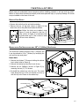
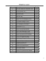
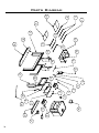
1
SHERWOOD INDUSTRIES IS AN ENVIRONMENTALLY RESPONSIBLE COMPANY. THIS MANUAL IS PRINTED ON RECYCLED PAPER.
PLEASE KEEP THESE INSTRUCTIONS FOR FUTURE REFERENCE
Venice
Wood Stove
BY: SHERWOOD INDUSTRIES LTD
OWNER’S MANUAL
Models: 1200-V & 1700-V Insert
INSTALLER:
Leave this manual with the wood stove.
CONSUMER:
Retain this manual for future reference.
Contact your local building or fire officials,
or the authority having jurisdiction about
restrictions and installation inspection
requirements in your area.
PLEASE READ THIS ENTIRE MANUAL BEFORE INSTALLATION AND USE OF THIS WOOD
BURNING ROOM HEATER. FAILURE TO FOLLOW THESE INSTRUCTIONS COULD RESULT
IN PROPERTY DAMAGE, BODILY INJURY OR EVEN DEATH.
Tested &
Listed By
C
O-T L
OMNI-Test Laboratories, Inc,
Beaverton
Oregon USA
This heater meets the U. S. Environmental Protection Agencies emission limits
for wood heaters sold after July 1st, 1990. Under specific conditions this heater
has been shown to deliver heat at rates ranging from 11,479 to 34,196 BTU per
hour for the 1200-V and from 9,425 to 31,780 BTU per hour for the 1700.
50-2034
Table of Contents
Safety Precautions..........................................................................................3
Operating Instructions.....................................................................................4
Building Your Fire.................................................................................5
How It Works......................................................................................9
Specifications................................................................................................10
Air Control.........................................................................................10
Specifications.....................................................................................10
Clearances To Combustibles - 1200-V Insert.........................................11
Clearances To Combustibles - 1700-V Insert.........................................12
Dimensions - 1200-V Insert.................................................................13
Dimensions - 1700-V Insert.................................................................14
Installation...................................................................................................15
Removal From Pallet..........................................................................15
Modifications For Installation with 191/16” (484mm) High Lintel...........15
Masonry Fireplace Installation.............................................................16
Installation Using A Block-Off Plate For USA Only..................................19
Model 1200-V Brick Placement & Tube Locations.................................21
Model 1700-V Brick Placement & Tube Locations..................................22
C-Cast Ceramic Baffle Installation........................................................23
Fan Wiring Diagrams..........................................................................23
Fan Removal......................................................................................24
Removal Of Face................................................................................25
Installation Of The Surround Panel......................................................25
Rating Label.................................................................................................26
Parts List......................................................................................................27
Parts Diagram...............................................................................................28
Warranty......................................................................................................29
Installation Data Sheet..................................................................................32
2
Safety Precautions
FOR SAFE INSTALLATION AND OPERATION OF YOUR “ENVIRO” WOOD
STOVE, PLEASE CAREFULLY READ THE FOLLOWING INFORMATION:
● Please read this entire manual before you install and use your new woodstove. Failure to
follow instructions may result in property damage, bodily injury or even death. Be aware
that local Codes and Regulations may override some items in this manual. Check with your
local inspector.
● If this appliance is not properly installed, operated and maintained, a serious house fire could result.
Do not use any makeshift materials during installation, maintenance, or replacement.
● Never place wood, paper, furniture, drapes or other combustible materials near the stove. Do not let
children or pets touch it when it is hot.
● Operate only with the door tightly closed and burn wood directly on the stove hearth. Do not operate
if the door glass is broken or a gasket is missing or damaged. Do not alter the combustion air control
valves. Dangerous overfiring could occur which could ignite creosote in the chimney or cause a house
fire.
● At least 12 square inches (77.4 cm2) of fresh outside air should be admitted into the room or directly
to the stove through a 4 inch (10.16 cm) diameter pipe. For the stove to operate combustion-air must
be supplied through either the bottom or the back of the pedestal.
● Do not burn coal or charcoal as there is danger of carbon monoxide being produced. Do not use
chemical fluids to start or re-fresh the fire. Do not burn garbage or flammable fluids such as gasoline,
grease, naphtha or engine oil. Never let the stove become hot enough to get any part red or glowing
red.
● Burning wet, unseasoned wood could cause excessive creosote accumulation in the flue pipe. When
ignited, it could cause a chimney fire that could result in a serious house fire.
● Do not use grates, andirons or any other methods to support or raise the fire up off the hearth of the
appliance.
●This appliance is tested to ULC-S627 Standard for Space Heaters for Use with Solid Fuel, ULC-S628
Standard for Fireplace Inserts, & UL 1482 Standard for Safety for Solid-Fuel Type Room Heaters.
● Both the 1200-V & 1700-V Fireplace Inserts are approved for installed into a zero-clearance fireplaces
in the U.S. In Canada refer to local building or fire officials for restrictions and installation inspection
● In Canada the existing chimney must be lined to the termination for all masonry installs.
IMPORTANT: The following must be done
to ensure proper operation. Failure to do so
will cause extreme overheating and possible
personal injury or property damage:
• If an outside air supply has not been added to
this appliance, please ensure that the 4” inch
fresh air outlet on the back of the pedestal is
removed.
3
Operating Instructions
FIRST START
When first installed, the chimney, firebricks and steel are cold and it usually takes several hours on a fairly
high burn for them to become hot and dry enough for the stove to function well. We recommend during
the unit’s first burn that a door and window are opened to vent the smoke and fumes created from the
unit’s paint curing. The paint will smell a little for the first burn or two as it cures.
DISPOSAL OF ASHES:
If you let the ashes accumulate two or three inches on the floor they tend to burn themselves up.
The fireplace insert models do not have and ash drawer so the ashes will need to be scooped into a metal
container with a tightly fitting lid. Place the closed container on a non-combustible floor, well away from
combustible materials.
If the ashes are to be buried in soil or otherwise locally dispersed, keep them in a closed container until
all cinders have cooled. Small amounts of cold wood ash can be used in the garden or compost.
FAN OPERATION:
All models have been approved for operation with the fans supplied by the manufacturer. On medium
or high burns, using a fan will increase the heat transfer slightly. Route the power supply cord along the
floor behind the stove where it will remain cool.
1. Plug the fan assembly into a standard three (3) prong grounded electrical receptacle.
2. An auto/off/manual rocker switch allows the fan to be turned on manually, or automatically. When this
switch is up, it will be set to manual operation; the center position is off, and when pushed down, it
will be set to automatic.
3. In automatic mode set the rotary switch to the desired setting, once operating temperature is reached,
the fan temperature sensor will turn the fan on. When the unit cools down, the fan temperature
sensor will shut the fan off automatically.
4. In manual mode the fan can be turned on and off any time using the rotary switch.
REPLACING THE GLASS:
Never strike or slam the door, hit the glass or let burning wood rest against it. If the glass cracks when
the fire is burning, do not open the door until the fire is out and do not operate the stove again until
the glass has been replaced. If the glass is damaged in any way, a factory replacement is required (see
“Parts List”). To replace the glass, remove the steel retaining clips and all loose glass. Replace only with
Neoceram 5 mm glass 16.61” (422 mm) x 10.63” (270 mm) and wrap the edges with 0.125” (3.2 mm) x
0.5” (13 mm) self-adhesive fiberglass gasket.
Wear gloves when handling damaged glass door assembly to prevent personal injury. When the glass
door assembly is being transported, it must be wrapped in newsprint and tape and/or a strong plastic bag.
The glass must be purchased from an ENVIRO dealer. No substitute materials are allowed.
FIRE EXTINGUISHER AND SMOKE DETECTION:
All homes with a solid fuel burning stove should have at least one fire extinguisher in a central location
known to all in the household and a smoke detection devise in the room containing the stove. If it sounds
the alarm, correct the cause but do not deactivate. You may choose to relocate the smoke detection
devise within the room; DO NOT REMOVE THE SMOKE DETECTOR FROM THE ROOM.
4
Operating Instructions
CREOSOTE - ITS FORMATION AND REMOVAL:
When wood is burned slowly, it may produce tar and other vapors that, combined with moisture, form
creosote. These vapors condense in the relatively cooler chimney flue of a slow burning fire and, if
ignited, make an extremely hot fire. Therefore, the smoke pipe and chimney should be inspected biweekly during the heating season to determine if a build-up has occurred. If creosote has accumulated
it should be removed to reduce the risk of a chimney fire.
MAINTENANCE:
At the end of each heating season clean the chimney and the smoke pipe. If soot has accumulated above
the top baffle bricks, remove, clean, and then replace them. If the secondary air tube is badly eroded,
replace it. Replace worn door gaskets and broken bricks as needed.
FAILURE TO INSPECT AND CLEAN YOUR CHIMNEY SYSTEM REGULARLY CAN RESULT IN A
CHIMNEY FIRE, WHICH COULD DAMAGE THE CHIMNEY OR CAUSE A HOUSE FIRE.
CHIMNEY OR RUN AWAY FIRE:
1. Call local fire department (or dial 911)
2. Close the draft fully
3. Examine the flue pipes, chimney, attic, and roof of the house, to see if any part has become hot
enough to catch fire. If necessary, spray with fire extinguisher or water from the garden hose.
4. Do not operate the stove again until you are certain the chimney and its lining have not been
damaged.
Building Your Fire:
Proper operation of your stove will help to ensure safe, efficient heating. Please take a few moments to
review these simple operating procedures.
IMPORTANT: Please be aware when loading your stove that the air tubes in the rear are lower.
1. Fuel Selection:
This stove is designed to burn natural wood only. Higher efficiencies and lower emissions generally
result when burning air-dried seasoned hardwoods, as compared to softwoods or to green or freshly cut
hardwoods. DO NOT BURN the following: treated wood, coal, garbage, solvents, colored papers, or trash.
Burning these may result in the release of toxic fumes and may poison or render the catalytic ineffective.
Burning coal, cardboard, or loose paper can produce soot, or large flakes of char or fly ash that can coat
the combustor, causing smoke spillage into the room, and rendering the combustor ineffective.
2. Building/Maintaining a Fire:
a) Open the primary air slide by pulling it all the way to the right.
b) Place a base of crumpled uncolored newspaper in the bottom of the stove. Lay pieces of kindling on
top of the newspaper and light it.
CAUTION: “Never use gasoline, gasoline-type lantern fuel, kerosene, charcoal lighter fluid,
or similar liquids to start or “freshen up” a fire in this heater. Keep all such liquids well
away from heater while it is in use.
c) As the kindling begins to burn, add several larger pieces of wood until the fire is burning well. At this
point, regular size logs may be added.
NOTE: Until the fire is burning well, leave the air controls fully open.
5
Operating Instructions
d) Regulate the heat output of the stove by adjusting the air controls to allow a larger fire and vice versa.
A short period of experimentation with the control settings will allow you to regulate the heat output
to keep your home comfortable.
Do not use a grate or elevate the fire. Build wood fire on the stove firebox hearth floor.
3. Refueling the Stove:
Use a long pair of gloves (barbecue gloves) when feeding the fire because these stoves burn at the front.
They are clean and efficient but they are also very hot and gloves are useful. Keep a small steel shovel
and whisk nearby for moving a log or lifting a fallen ember and for keeping the hearth clean.
a) Before attempting to add fuel to the stove, OPEN the damper control fully by pulling it all the way out.
This allows the chimney to carry away the additional smoke, which occurs when the door is open.
b) DO NOT OVERLOAD THE STOVE. Normally, three or four logs will provide heat for several hours.
Never operate this stove where portions glow red hot.
c) DO NOT OVERFIRE. If the heater or chimney connector glows, you are overfiring.
d) CAUTION: DO NOT PLACE FUEL WITHIN SPACE HEATER INSTALLATION CLEARANCES OR WITHIN
THE SPACE REQUIRED FOR CHARGING AND ASH REMOVAL.
4. For Maximum Efficiency:
When the stove is hot, load it fully to the top of the door opening and burn at medium low settings. When
the fuel is mostly consumed, leaving a bed of red coals, repeat the process. Maximum heat for minimum
fuel occurs when the stove top temperature is between 250°F (120°C) and 550°F (290°C). The most
likely causes of dirty glass are: not enough fuel to get the stove thoroughly hot, burning green or wet
wood, closing the draft until there is insufficient air for complete combustion, or a weak chimney draw.
Indeed, the cleanness of the glass is a good indicator of the stove operating efficiently.
Helpful Hints Worth Repeating
1. Helpful advice on the correct way to start your fire.
a) You will need small pieces of dry wood, called kindling, and paper. Use only newspaper or paper
that has not been coated or had other materials glued or applied to it. Never use coated (typically
advertising flyers) or coloured paper.
b) Always open the door of the wood stove slowly to prevent suction and drawing smoke into the
room.
c) Crumple several pieces of paper and place them in the center of the firebox and directly onto the
firebricks of the wood stove. Never use a grate to elevate the fire.
d) Place small pieces of dry wood (kindling) over the paper in a “teepee” manner. This allows for good
air circulation, which is critical for good combustion.
e) Light the crumpled paper in 2 or 3 locations. Note: It is important to heat the air in the stovepipe for
draft to start.
f) Fully open the air controls of the wood stove and close the door until it is slightly open, allowing for
much needed air to be introduced into the firebox. Never leave the door fully open, as sparks from
the kindling may fly out of the stove, causing damage or injury. As the fire begins to burn the kindling,
some additional kindling may be needed to sustain the fire. DO NOT add more paper after the fire has
started.
6
Operating Instructions
g) Once the kindling has started to burn, add some smaller pieces of seasoned, dry firewood. Note:
Adding large pieces at the early stages will only serve to smother the fire. Continue adding small pieces
of seasoned dry firewood, keeping the door slightly open until each piece starts to ignite. Remember
to always open the door slowly between placing wood into the fire.
h) Once the wood has started to ignite and the smoke has reduced, close the wood stove door fully. The
reduction of smoke is a good indication that the draft in the chimney has started and good combustion
is now possible. Larger pieces of seasoned, dry firewood can now be added when there is sufficient
space in the firebox. Adjust the air control setting to desired setting. Note: The lower the air control
setting, the longer the burn time of your firewood.
2. What type of wood is best to use as firewood?
Both hardwood and softwood burn well in this stove. Both woods contain about 8,000 BTU/lb (18,570
KJ/Kg), but hardwood is generally more dense, will weigh more per cord, and burns a little slower and
longer. Cutting firewood so that it will fit horizontally, front to back, makes it easier loading and less likely
for the fuel to roll on the glass. Except for a cold start, there is no need to crisis-cross the logs. Ideal
length for the logs used in the 1200-V would be about 16“ (381 mm) but it can burn pieces up to 18”
long. Ideal length for the logs used in the 1700-V would be about 18“ (381 mm) but it can burn pieces
up to 20” long logs. Burn only dry, seasoned wood. It produces more heat and less soot or creosote.
Freshly cut wood has about 50% moisture. A 10 pound (4.5 Kg) log contains 5 pounds (2.3 Kg) of water.
To season firewood, split and stack it so that air can get to all parts of the wood. Burn beach wood only
if its salt content has been washed away in a season of rain and then the wood dried. To prevent smoke
spillage when refueling, open the door slowly.
3. What does dry, seasoned wood mean?
Wood that has been dried for a period of one year in a well-ventilated and sheltered area would be
considered dry, seasoned wood. Wood from slow-growing trees is generally considered better than wood
from fast-growing trees. To season firewood, split and stack it so that air can get to all parts of the
wood.
4. Will following the above-listed steps for starting a fire mean perfect results every time?
The quick answer is ‘most of the time’. There are many variables that may affect your success when
starting a fire. Most of those variables and how to deal with them will be learned through experience.
Your ability to start a good fire will significantly increase with time and patience. Some of the reasons for
poor stove performance will be covered in the next section of these instructions.
5. Why can’t I get the fire lit?
Damp or wet wood and poor drafts are the main reasons for poor results in starting a fire. Always use
dry, seasoned wood for your fire. Even wood dried for two years will be difficult to ignite if it has become
wet.
6. Is it normal for soot to cover the glass at the beginning of a fire?
Your stove has been built with an air-wash system that will help keep the glass clear when the firebox
has reached a good operating temperature and has a good draft. Normally a hot stove will keep the glass
clean, but if you must clean the glass, use a soft cloth with no abrasive and clean only when cold. Cold
firebox temperature and poor draft cause sooting of the glass. Once the firebox temperature and the
draft increase, the soot will burn off.
7
Operating Instructions
7. What is draft?
Draft is the ability of the chimney to exhaust or draw smoke produced during the normal combustion
process. Too much draft may cause excessive temperatures in the appliance and may damage the
appliance. Inadequate draft may cause backpuffing or “plugging” of the chimney. There is a certain
amount of draft that is required to allow for your stove to function at its’ highest efficiency. A water
column gauge can be used to reference this amount.
8. What can cause a poor draft?
The most common factors for poor draft are:
a) Air supply b) Environmental conditions c) Cold chimney temperature
d) Poor chimney installation and maintenance
e) Atmospheric pressure
a) Air supply – Inside the home, normal household appliances such as clothes dryers and forced-air
furnaces compete for air, resulting in air starvation to the fire. This creates a condition in the house
known as negative pressure. When a house experiences negative pressure, the combustion gases
can be drawn from the chimney and into the house. This condition is commonly referred to as downdrafting. Increased amounts of insulation, vinyl windows, extra caulking in various places and door
seals can all keep heat in but may also make a home too airtight. An easy way to stop negative
pressure in a home is to crack a window in the room containing the stove.
b) Environmental Conditions - High trees, low-lying house location such as in a valley, tall buildings or
structures surrounding your house and windy conditions can cause poor draft or down-drafting.
c) Cold Chimney Temperature - Avoid cold chimney temperatures by burning a hot fire for the first fifteen
to forty minutes, being careful not to over-fire the stove. If any part of the chimney or parts of the
stove start to glow, you are over-firing the stove. Where possible, install a temperature gauge on the
chimney so temperature drops can be seen.
d) Chimney Installation and Maintenance - Avoid using too many elbows or long horizontal runs. Too short
a chimney can cause difficult start-up, dirty glass, back smoking when door is open, and even reduced
heat output. Too tall a chimney may prompt excessive draft, which can result in very short burn times
and excessive heat output. If in doubt, contact a chimney expert and/or chimney manufacturer for
help. Clean chimney, rain caps and especially the spark arrestor regularly, to prevent creosote buildup, which will significantly reduce chimney draw and possibly a chimney fire.
Note: These instructions are intended as an aid and do not supercede any local, provincial or state
requirements. Check with officials or authorities having jurisdiction in your area.
8
Operating Instructions
How It Works:
Exhaust Smoke
Convection Heat
1/2"
Ceramic baffle;
reflects heat down
to burn the particles
in the smoke.
Primary air; window
air wash (cooler air to
keep the glass clean).
Secondary air tubes;
creates a second burn
on the particles in the
smoke for a more efficient
& cleaner burn.
Radiant Heat
Pilot air through
Twin pilot injection ports.
Slider plate; used
for air flow control.
Intake air.
Figure 1: 1200-V Air Flow Path.
Exhaust Smoke
1/2"
Ceramic baffle;
reflects heat down
to burn the particles
in the smoke.
Convection Heat
Primary air; window
air wash (cooler air to
keep the glass clean).
Secondary air tubes;
creates a second burn
on the particles in the
smoke for a more efficient
& cleaner burn.
Radiant Heat
Pilot air through
Twin pilot
injection ports.
Slider plate; used
for air flow control.
Seasoned Firewood
Intake air.
Figure 2: 1700-V Air Flow Path.
9
Specifications
Air Control:
The air wash and pilot air (control the amount of air to the fire) are controlled by the rod located on the
right side of the unit. To increase your air, pull the rod out and to decrease, push the rod in. All the units
have a secondary air that flows through the tubes at the top of the firebox, just below the baffles.
Pull this control all the way out when first starting the
stove. Once the fire has been established you may
adjust this control to set the burn rate of the fire. If
this damper is closed at first start-up, the fire will burn
very slowly and could soot the appliance.
When shutting down the stove, fully open the air
control. This allows the chimney temperatures to
remain as high as possible for as long as possible. Cold
chimney temperatures create creosote.
Increase air - pull rod out
Decrease air - push rod in
Figure 3: Air Control Rod.
Specifications:
Table 1: 1200-V & 1700-V General Information.
Model
Width x Depth
Height of body
Fire box size
1200 Insert
1700 Insert
27¾” x 21½”
(705 mm x 546 mm)
27¾” x 26”
(705 mm x 660 mm)
191/16” (484 mm) or 199/16” (497 mm)
16.1” x 18.25” x 11.15”
(409 mm x 464 mm x 283 mm)
20.65” x 18.25” x 11.95”
(525 mm x 464 mm x 304 mm)
1.85 feet3
(0.0526 meter3)
2.5 feet3 (0.0708 meter3)
800 - 1,500 feet2
(74.3 - 139.4 meter2)
1,000 - 2,200 feet2
(92.9 - 205.4 meter2)
**E.P.A. output rating
11,479 to 34,196 BTU/hour
(3,361 to 10,013 watt)
9,425 to 31,780 BTU/hour
(2,760 to 9,306 watt)
*Duration on low burn
6 -10 hours
8 - 12 hours
Weight with packaging
335 lb (151.95 Kg)
390 lb (176.90 Kg)
3.3 grams/hour
(0.116 oz/hour)
4.48 grams/hour
(0.158 oz/hour)
(depth x width x height)
Capacity
* Approximate heating area
E.P.A. Emissions
Surround Panels
Standard (width x height)
46⅛” x 28” (1171 mm x 711 mm)
Oversized (width x height)
46⅛” x 33⅛” (1171 mm x 843 mm)
Rating Label Location
10
Side of Unit; Behind Right Shroud
Specifications
Clearances To Combustibles - 1200-V Insert:
A Minimum clearance to an unshielded side wall
10” (254 mm)
B Minimum clearance to an unshielded 8” (203
mm) mantel
21” (533 mm)
C Minimum top facing (protruding ¾” [19 mm])
clearance
17½” (445 mm)
D Minimum side facing (protruding ¾” [19 mm])
clearance
1” (25 mm)
Adjacent wall
Table 2: 1200-V Insert Clearance to Combustibles.
E † From front of door opening to edge of floor USA 16” (406 mm)
protection
CND 18” (450 mm)
F † From side/back of unit to edge of floor
protection
USA 6” (152 mm)
CND 8” (200 mm)
B
C
D
A
E
F
† FLOOR PROTECTION:
If unit is raised 0” - 2” (0mm-51mm); 1” (25mm) non-combustible material with k value = 0.84 or equivalent.
If unit is raised 2” - 8” (51mm-203mm); ½” (13mm) non-combustible material with k value = 0.84 or equivalent.
If unit is raised greater than 8” (203 mm) or more; any non-combustible material can be used.
Table 3: Reduction in (B) Minimum Clearance from 1200-V to 8” (203 mm) Mantel.
Type of protection
Modified Clearance
A minimum of .013” (0.33mm) sheet metal spaced out 1” (25mm) by noncombustible spacers.
10½” (267 mm)
Ceramic tiles, or eqivalent non-combustible material on non-combustible
supports and spaced out 1” (25mm) by non-combustible spacers.
14” (357 mm)
Ceramic tiles, or eqivalent non-combustible material on non-combustible
supports with a minimum of .013” (0.33mm) sheet metal spaced out 1”
(25mm) by non-combustible spacers.
10½” (267 mm)
NOTES:
(1) Mantel protection must have at least 3” (75mm) edge clearance on all sides, except as provided in Note 4.
(2) If an adhesive is used to support non-combustible material, it shall not lose adhesive qualities at temperatures
likely to be encountered and shall not contribute a significant combustible load.
(3) Heat shield mounting hardware attached to combustible materials must be placed at the lateral extremities of
the shield.
(4) Minimum clearance to unprotected walls and ceilings must be maintained.
Table 4: 1200-V Insert Minimum Fireplace Size.
Masonry
Zero Clearance
Minimum Depth
13½” (343 mm)
14” (279 mm)
Minimum Width at back of fireplace
22⅜” (568 mm)
23” (584 mm)
Minimum Width at front of fireplace
27” (686 mm)
27¼” (692 mm)
33¾” (857 mm)
34” (864 mm)
19¼” (489 mm)**
or 19¾” (502 mm)
20” (508 mm)
Minimum Width at front of fireplace to include shroud
Minimum Height
** If the masonry lintel height is only 19¼” (489 mm) to 19¾” (502 mm) refer to Installation - Modifications For
Installation with 19¼” (489 mm) High Lintel - Insert
11
Specifications
Clearances To Combustibles - 1700-V Insert:
A
Minimum clearance to an unshielded side wall
10” (254 mm)
B
Minimum clearance to an unshielded 8” (203
mm) mantel
24” (610 mm)
C
Minimum top facing (protruding ¾”
mm]) clearance
[19
D
Minimum side facing (protruding ¾”
mm]) clearance
[19
19½” (495 mm)
1” (25 mm)
E
† From front of door opening to edge of floor
protection
USA 16” (406 mm)
CND 18” (450 mm)
F
† From side/back of unit to edge of floor
protection
USA 6” (152 mm)
CND 8” (200 mm)
Adjacent wall
Table 5: 1700-V Insert Clearance to Combustibles.
B
C
D
A
E
F
† FLOOR PROTECTION:
If unit is raised 0” - 2” (0mm-51mm); 1” (25mm) non-combustible material with k value = 0.84 or equivalent.
If unit is raised 2” - 8” (51mm-203mm); ½” (13mm) non-combustible material with k value = 0.84 or equivalent.
If unit is raised greater than 8” (203 mm) or more; any non-combustible material can be used.
Table 6: Reduction in (B) Minimum Clearance from 1700-V to 8” (203 mm) Mantel.
Type of protection
Modified Clearance
A minimum of .013” (0.33mm) sheet metal spaced out 1” (25mm) by noncombustible spacers.
12” (305 mm)
Ceramic tiles, or eqivalent non-combustible material on non-combustible
supports and spaced out 1” (25mm) by non-combustible spacers.
16⅛” (408 mm)
Ceramic tiles, or eqivalent non-combustible material on non-combustible
supports with a minimum of .013” (0.33mm) sheet metal spaced out 1”
(25mm) by non-combustible spacers.
12” (305 mm)
NOTES:
(1) Mantel protection must have at least 3” (75mm) edge clearance on all sides, except as provided in Note 4.
(2) If an adhesive is used to support non-combustible material, it shall not lose adhesive qualities at temperatures
likely to be encountered and shall not contribute a significant combustible load.
(3) Heat shield mounting hardware attached to combustible materials must be placed at the lateral extremities of
the shield.
(4) Minimum clearance to unprotected walls and ceilings must be maintained.
Table 7: 1700-V Insert Minimum Fireplace Size.
Masonry
Zero Clearance
18” (457 mm)
18½” (470 mm)
Minimum Width at back of fireplace
22⅜” (568 mm)
23” (584 mm)
Minimum Width at front of fireplace
27” (686 mm)
27¼” (692 mm)
33¾” (857 mm)
34” (864 mm)
19¼” (489 mm)**
or 19¾” (502 mm)
20” (508 mm)
Minimum Depth
Minimum Width at front of fireplace to include shroud
Minimum Height
** If the masonry lintel height is only 19¼” (489 mm) to 19¾” (502 mm) refer to Installation - Modifications For
Installation with 19¼” (489 mm) High Lintel - Insert
12
473/8" (1203mm)
3413/16" (885mm)
225/16" (566mm)
Figure 4: 1200-V Insert Dimensions.
207/8"
(530mm)
2615/16"
(684mm)
2115/16" (557mm)
201/16" (509mm)
219/16" (548mm)
191/16"
(484mm) 207/8"
or
(529mm)
199/16"
(497mm)
5" (127mm)
135/16" (338mm)
Specifications
Dimensions - 1200-V Insert:
13
Specifications
Dimensions - 1700-V Insert:
225/16" (566mm)
3413/16" (885mm)
473/8" (1203mm)
2615/16"
(684mm)
207/8"
(530mm)
Figure 5: 1700-V Insert Dimensions.
261/8" (663mm)
249/16" (624mm)
261/2" (672mm)
177/16" (453mm)
5" (127mm)
191/16"
(484mm)
207/8"
or
(529mm)
199/16"
(497mm)
14
Installation
Please read and understand these instructions before installing pedestal or ash pan and leg option.
Failure to follow these instructions carefully could cause personal injury or property damage. All screws
are pre-installed on the base of the unit.
Removal From Pallet:
• Remove the bricks from the unit before starting.
• Remove the two (2) lag bolts (shown in Figure 6) that
secure the unit to the pallet from inside the firebox.
Note: Before the bricks are installed, rivets
(Figure 2) must be placed in the two (2)
holes (shown in Figure 7) in the firebox that
lag bolts came out of. This is done to make
unit burn more efficiently.
Figure 7:
Rivet.
Figure 6: Bolts to remove.
Modifications For Installation with 191/16”
(484mm) High Lintel:
The Venice has a factory height of 199/16” (497mm) and
it can be reduced to 191/16” (484mm) by modifying the
unit and the surround panel.
Insert Unit:
1. Remove the thirteen T-20 screws holding the cabinet
top in place (refer to Figure 8).
2. Remove the cabinet top and flip it onto its top.
3. Remove the Air Deflector (shown in Figure 9) by
removing the two (2) T-20 screws.
4. Re-install the cabinet top onto the unit. The screw
holes along the top of the unit should now line up
with the top set of holes on the cabinet top.
Figure 8: Removing Cabinet Top from Unit.
Air Deflector
Insert Cabinet Top
Figure 9: Removing Air Deflector onto Cabinet Top.
15
Installation
Masonry Fireplace Installation:
Unless you are experienced, we recommend installation by your dealer or a
professional installer.
Install only in a masonry fireplace with a good-condition chimney at least 15 ft (4.6 m) high, both of
which have been constructed in accordance with the building code. Refer to Tables 4 and 7 for minimum
masonry fireplace dimensions. Be sure the fireplace and chimney are clean and sound without any cracks
or loose mortar. Do not remove any bricks or mortar from the fireplace.
Rain Cap
Steel Plate or Flashing
Flexible or Rigid 6"
Stainless Steel Liner
If there is a combustible floor in front
of the masonry fireplace, the fireplace
insert must be 8” (203 mm) above the
combustible floor, and floor protection must
be provided 18” (457 mm) in front of the
fireplace insert and 8” (203 mm) to each
side of the unit. Refer also to Specifications
- Clearances To Combustibles - 1200-V Insert
and Specifications - Clearances To Combustibles
- 1700-V Insert.
1. Remove any fireplace damper or fasten
in a permanent open position.
Mantel
Top Facing
Damper Removed
or Fastened Open
Surround Panel
Sheet Metal Screws
Fastening Collar to
Stainless Steel Liner
USA 16” (406 mm)
CND 18” (450 mm)
Floor
8"
Protection (203 mm)
Masonry Fireplace
Combustible Floor
Figure 10: Insert Installation into existing fireplace with
hearth.
16
2. (IN CANADA) The stove is vented with
a 6” stainless steel liner that goes directly to
the top of the chimney and is covered with
a rain cap. The chimney top is sealed with
a flashing or steel plate that supports the
weight of the chimney liner. The installation
must conform to the liner’s manufacturer’s
instructions.
This fireplace must be installed with a
continuous liner of 6” diameter (CANADA
ONLY) extending from the fireplace insert to
the top of the chimney. The chimney liner
must conform to the class 3 requirements of
ULC-S635 Standard for Lining Systems for
Existing Masonry or Factory-Built Chimneys
and Vents, or ULC-S640 Standard for Lining
Systems for New Masonry Chimneys.
(IN U.S.A.)The appliance when installed,
must follow local building codes, in the
absence of local building codes, with the
current NFPA 211 Standard for Chimneys,
Fireplaces, Vents, and Solid Fuel-Burning
Appliances.
Installation
The flue collar is removable for installations
into fireplaces with low openings.
USA 16” (406 mm)
CND 18” (450 mm)
Floor Protection
Masonry Fireplace
8"
(203 mm)
Combustible Floor
Figure 11: Insert Installation into existing fireplace without
hearth.
a) Remove the rear two (2) secondary
air tube and C-Cast Ceramic Baffles,
if installed (see C-Cast Ceramic Baffle
Installation). Remove the secondary air
tubes by placing a screwdriver (any style
except flat head) into one of the air holes
and tapping it with a hammer/mallet to
the left.
b) Unscrew the two (2) nuts on top of the
inside of the firebox, using a 9/16” wrench
or socket (see Figure 13). The Flue Collar
Clamps will slide off the bolts.
c) Pull the removable flue collar off the top
of the unit.
d) Attach the flue collar to the venting pipe
using sheet metal screws.
e) Push the unit into place while trying to
keep the collar attached to venting close
to the opening on the top of the unit.
Vent pipe
USA 16” (406 mm)
CND 18” (450 mm)
Masonry Fireplace
Collar Puller
Combustible Floor
1" (25mm)
Non-Combustible Board (K 0.84)
Figure 12: Insert Installation into existing floor level
masonry fireplace.
f) Place the Collar Puller, over the two bolts of the Flue
Collar and pull it into place (see Figure 14). Ensure that
the bolts are to the left and right of the hole. If they are
not, the front secondary air tube will need to be removed
in order to install or remove the C-Cast Ceramic Baffles.
g) Slide the Flue Collar Clamps and washers over the bolts,
and screw the nuts back onto the bolts.
h) Re-install C-Cast Ceramic Baffles and the rear two
(2) secondary air tube (see C-Cast Ceramic Baffle
Installation).
3. There are four (4) leveling legs (shown in Figure 15), two
(2) on each side, one at the back and one at the front of the
unit. Adjust the legs using a ⅜” wrench to ensure the unit is
stable.
Removable
Flue Collar
Gasket
Firebox Top
Cut-away
Flue Collar Clamp
Washer
Nut
Figure 13: Attaching removable flue collar.
17
Installation
Figure 14: Removable flue collar in place.
4. Screw or nail the provided metal plate with the
wording “THIS FIREPLACE HAS BEEN ALTERED
TO ACCOMMODATE A FIREPLACE INSERT AND
SHOULD BE INSPECTED BY A QUALIFIED PERSON
PRIOR TO THE RE-USE AS A CONVENTIONAL
FIREPLACE.” to the inside of the fireplace.
Leveling Legs
Figure 15: Leveling legs.
Surround Panel Sealed Installation For USA Only:
Note: Though this is an allowable installation, we do not recommend it because of the possibility of poor
draft, and therefore poor stove performance.
NOTE: To use this type of installation we
recommend your chimney have a minimum
cross-sectional area of 28 and a maximum of
144 square inch. If it is not within this range
your chimney may not have sufficient draw
for the fireplace to operate correctly. The
required cross-section may vary depending
on climate and if the chimney is inside (better)
or outside.
Before starting this type of installation refer
to Installation - Masonry Fireplace Installation
- Insert for additional information. For
clearances refer to Specifications - Clearances
To Combustibles - 1200-V Insert and
Specifications - Clearances To Combustibles 1700-V Insert.
Damper Removed
or Fastened Open
1. Before the face plate is installed onto
the unit, glue a 6” (150mm) wide R20
fiberglass insulation strip around the
perimeter of the back of the panels using
RTV silicon or stove gasket cement.
When the face plate is installed onto
the unit the insulation must overlaps the
fireplace opening to form a seal between
the masonry fireplace and the unit’s face
plate. Let the silicon or cement dry.
Mantel
Insulation Around the
Back of the Face Plate
Surround Panel
2. To make the installation of the surround
panel onto the unit easy have the unit 6”
(150mm) out from the fireplace,
3. Push the insert into the fireplace, allowing
the insulation to form a seal between
the panels and the fireplace. Tuck any
exposed insulation behind the face plate.
18
USA 16” (406 mm)
CND 18” (450 mm)
Masonry Fireplace
Figure 16: Installation with Surround Sealed.
Installation
Installation Using A Block-Off Plate For USA Only:
If this unit is to be installed into a masonry fireplace or a zero-clearance fireplace with a direct connection
you must install a non-combustible seal-off device such as a block-off plate or damper adapter. By
installing a block-off plate you seal the chimney, ensuring that no smoke enters the home and sealing the
chimney to encourage draft. To construct a block-off plate follow the below steps.
1. Determine where the block-off plate will be installed; above the top of the firebox (it must be high
enough to easily install the connection pipe) but below the damper area. Look for a location that
is level and in an area where the plate can be mounted
easily.
The measurement that will be needed are as followed (refer
to Figure 17 and 18):
A - The width at the front of the firebox at the height where
the block-off plate will be installed.
B - The width at the back of the firebox at the height where
the block-off plate will be installed.
C -Then depth of the block-off needed (the distance
between A and B).
D - The distance of the center of the flue to the front of the
fireplace opening. Refer to Step 3.
NOTE: In general masonry fireplaces have square fireboxes
while zero-clearance (metal) fireplaces have domed firebox
tops. Therefore zero-clearance block-off plates may be more
difficult to install. Insulation may be used around the edges
to simplify sealing the plate.
B
A
C
2. Create a cardboard template of the dimensions with 2” (51
cm) wide flanges on each side. These flanges will be used to
mount the block-off plate to the inside of the firebox. Bend
the flanges downwards on the template and place it inside
the fireplace. Continue on if the template fits correctly in Figure 17: 3D of Dimensions needed from
its planned location. If the template does not fit, make a
the Fireplace.
new template with the required corrections until it does fit
B
correctly.
3. With the template in place, mark the location for the center
of the flue pipe when the unit is in place. If installing a
1200-V the distance will be approximately 8¼” or 9 15/16”
back from the fireplace opening. If installing a 1700-V the
distance will be approximately 12¾” or 14 7/16” back from
the fireplace opening. Remove the template and cut a 6¼”
diameter hole centered on this mark.
4. Using the template make the block-off plate of 24 gauge or
thicker steel. Drill two (2) holes in each flange for mounting
the plate.
C
D
A
Front of fireplace opening.
Figure 18: Layout of the Block-Off Plate.
19
Installation
5. Mount the block-off plate
using masonry screws in a
masonry fireplace and sheet
metal screws on a zeroclearance fireplace (screws
need only be long enough
to penetrate the first layer of
metal).
6. Insulate the block-off plate
using high - temperature
fiberglass insulation and
furnace cement.
Mantel
Damper must
be removed
Stainless steel chimney
connector must extend
12" (305mm) past the
block-off plate.
Block-off plate or
damper adaptor.
Zero-clearance
(metal) firebox
Surround Panel
IMPORTANT:
DO NOT modify
any part of the
ZC fireplace
USA 16” (406 mm)
CND 18” (450 mm)
Figure 19: Insert Install into a Zero-Clearance Fireplace.
Damper removed
or fastened open
Mantel
The stainless steel
chimney connector must
extend 12" (305mm) past
the block-off plate.
Block-off plate or
damper adaptor.
Surround Panel
USA 16” (406 mm)
CND 18” (450 mm)
Masonry Fireplace
Figure 20: Masonry Fireplace Direct Connection Insert Install.
20
7. After installing the unit into place and
the pipe through the block-off plate,
use high - temperature fiberglass
insulation and furnace cement to seal
any gaps between the pipe and blockoff plate (allow the cement to dry for
at least 24 hours before burning).
Before starting this type of installation
refer to Installation - Masonry Fireplace
Installation - Insert for additional
information. For clearances refer to
Specifications - Clearances To Combustibles
- 1200-V Insert and Specifications Clearances To Combustibles - 1700-V Insert.
See Figure 19 and 20 for examples of a
masonry fireplace and a zero-clearance
fireplace with a direct connection
Installation
Model 1200-V Brick Placement & Tube Locations:
COMPLETE THE STOVE AND SMOKE PIPE INSTALLATION BEFORE PLACING THESE BRICKS.
Tube E
Tube D
Tube A
ick
Br
l
a
e
rti
Pa
S iz
l
l
Fu rick
B
e
S iz
l
l
Fu rick
B
1. Place the three (3) full size
bricks along each side of the
firebox and one (1) full size
brick on either side of the back
of the firebox.
2. To place the floor bricks, lay
the two (2) partial bricks along
the back of the floor. Then on
the left, lay two (2) full size
bricks and on the right, lay a
full size brick in the center and
the half brick in the front (for
the ash dump). The spaces
between the bricks will soon
fill with ashes.
Figure 21: Brick Placement for 1200-V shown with Secondary Air
Channel and Tubes.
When replacing bricks, use only pumas type fire bricks.
TOTAL BRICKS:
12 - Full size bricks
2 - Partial bricks
9” long x 4.5” wide x 1.25” thick
(22.9 cm long x 11.4 cm wide x 3.2 cm thick)
9” long x 3” wide x 1.25” thick
(22.9 cm long x 7.6 cm wide 3.2 cm thick)
Removing Air Tube: If a secondary air tube needs to be removed, place a screwdriver (any style except
flat head) into one of the air holes and tap it with a hammer/mallet to the left until the right end of the
tube is freed. To installation a secondary air tube reverse the above instructions.
IMPORTANT: All secondary air tubes must be in place for proper operation.
21
Installation
Model 1700-V Brick Placement & Tube Locations:
COMPLETE THE STOVE AND SMOKE PIPE INSTALLATION BEFORE PLACING THESE BRICKS.
Tube C
Tube B
Tube A
ick
al Br
Parti
rick
ize B
Ful l S
rick
ize B
Ful l S
rick
ize B
S
l
l
u
F
1. Place the four (4) full size
bricks along each side of
the firebox and one (1) full
size brick on either side of
the back of the firebox.
2. To place the floor bricks, lay
the two (2) partial bricks
along the back of the floor.
Then on the left, lay three
(3) full size bricks and on
the right, lay two (2) full
size bricks in the center and
the half brick in the front
(for the ash dump). The
spaces between the bricks
will soon fill with ashes.
Figure 22: Brick Placement for 1700-V shown with Secondary Air Channel
and Tubes.
When replacing bricks, use only pumas type fire bricks.
TOTAL BRICKS:
16 - Full size bricks
2 - Partial bricks
9” long x 4.5” wide x 1.25” thick
(22.9 cm long x 11.4 cm wide x 3.2 cm thick)
9” long x 3” wide x 1.25” thick
(22.9 cm long x 7.6 cm wide 3.2 cm thick)
Removing Air Tube: If a secondary air tube needs to be removed, place a screwdriver (any style except
flat head) into one of the air holes and tap it with a hammer/mallet to the left until the right end of the
tube is freed. To installation a secondary air tube reverse the above instructions.
IMPORTANT: All secondary air tubes must be in place for proper operation.
22
Installation
C-Cast Ceramic Baffle Installation:
1. Slide the right C-Cast Ceramic Baffle in over the secondary air tubes at the top of the firebox. The tab
must be on the top and pointing towards the center and the smooth side is to face down.
2. Hook the outside edge of the baffle
over the top of the secondary air
chamber. This will make room to for the
installation of the left C-Cast Ceramic
Baffle.
3. Slide the left C-Cast Ceramic Baffle in
over the secondary air tubes. The tab
must be on the bottom and pointing
towards the center and the smooth side
is to face down.
Right Ceramic Baffle
Left Ceramic Baffle
4. Pull the baffles together in the middle
so the right tab rests on top of the left
tab. Ensure the baffles are flush with
the back and both sides of the firebox.
Note for insert models only: If the
bolts on the flue collar are not to the left
and right of the hole, the front secondary
air tube will need to be removed in order
to install or remove the C-Cast Ceramic
Baffles. To remove the front secondary
air tube place a screwdriver (any style
except flat head) into one of the air holes
and tapping it with a hammer/mallet to
the left.
Figure 23: Installation of C-Cast Ceramic Baffle.
Fan Wiring Diagrams:
This appliance, when installed, must be electrically connected and grounded in accordance with local
codes or in the absence of local codes, with the current CSA C22.1 CANADIAN ELECTRICAL CODE. Part
1, SAFETY STANDARDS FOR ELECTRICAL INSTALLATIONS, or THE NATIONAL ELECTRICAL CODE ANSI
/ NFPA 70 in the USA.
CAUTION Label all wires prior to disconnection when servicing controls. Wiring errors
can cause improper and dangerous operation. Verify proper operation after servicing.
DO NOT oil the fan bearings.
DO NOT cut or remove the grounding prong from the plug.
DO NOT route the power cord beneath the heater.
WARNING: This appliance is equipped with a three-prong (grounding) plug for your protection against
shock hazard and should be plugged into a properly grounded three-prong receptacle.
23
Installation
Fan
Black
Fan temperature
sensor
Black
Rocker Switch
Manual
Black
Off
Auto
Black
Black
Black
Black
White
Fan
controller
Power Supply
Figure 24: Fireplace Insert Fan Kit Wiring Diagram.
Fan Removal:
The Insert comes with the fan assembled installed
in the left shroud.
1) Disconnect all electrical connections for the fan
kit.
2) Remove the four (4) ½” hex head screws that
hold the fan mounting plate to the shroud.
3) Remove the fan control knob and nut from the
front of the shroud and pull the controls out the
back.
4) Install the fan kit into the new shroud by
following reversing steps 1 to 3. Refer to Fan
Wiring Diagram to ensure the fan is reconnected
properly.
Figure 25: Insert Unit with Fan.
24
Installation
Removal Of Face:
1.Remove the cast top from the unit
(lift up and forward)
2.Lift up and forward on the unit face,
the entire face and surround panel
will come away from the unit.
Figure 26: Removal of Face.
Installation Of The Surround Panel:
1.Loosen (but do not remove) the
four (4) ¼” screws holding the
cast top.
2. List the cast top off the unit and
place to the side.
3.Loosen the four (4) torx T-20
screws holding the face on the
unit.
4.Lift the face up and forward to
remove from the unit.
5. Attach the surround panel to the
face using the eight (8) torx T-20
screws provided (four per side).
6. Replace the face on the unit
and tighten the four torx T-20
screws.
7. Replace the cast top on the unit.
The four (4) ¼” screws can be
left loose.
Figure 27: Installation of Panel.
25
Rating Label
Tested &
Listed By
C
O-T L
Beaverton
Oregon USA
US
OMNI-Test Laboratories, Inc,
DO NOT REMOVE THIS LABEL / NE PAS ENLEVER CETTE ÉTIQUETTE
LISTED SOLID FUEL SPACE HEATER / IDENTIFIE COMME UN FOYER A COMBUSTIBLE SOLIDE
Model / Modèle:
Report/Rapport no.
Kodiak 1200 FS�
268-S-04-2
Kodiak 1200 Insert
268-S-05-2
Venice 1200 Insert
268-S-05-2
Certified for use in Canada & USA /
Certifié pour installation au Canada et aux Etats-Unis.
Kodiak 1700 Insert
268-S-06-2
�
Venice 1700 Insert
268-S-06-2
��
�
�
Serial No. / No. De Serié:
Modèles 1200 et 1700 items indépendants utilisables dans les maisons mobiles.
Testé selon ULC-S627-00, ULC-S628-93, & UL-1482.
États-Unis Environnemental Protection Agence, a certifié pour conformer au Juillet 1, 1990, les normes de particules d'émission.
Models 1200 and 1700 Freestanding units suitable for use in mobile homes.
Tested to ULC-S627-00, ULC-S628-93, & UL-1482.
US Environmental Protection Agency, certified to comply July 1, 1990, particulate emission standards.
Ce dispositif doit entre installé et opéré conformément aux instructions d'installation et d'opération du manufacturier contactez le
service local de l'inspection des bâtiments ou l'officier pompier concernant les restrictions et l'inspection d'installation dans votre
localité. Utiliser des connecteurs répertoriés 24 MSG noir ou 25 MSG en acier bronzée de 6" (150 mm) minimum, et une
cheminée de fabrication industrielle, appropriée pour utilisation avec des combustibles solides ou avec une cheminée de
maçonnerie. Vérifiez les précautions a prendre exigées parle code local et les instructions du manufacturier concernant les
conditions pour passer la cheminée a travers un mur ou un plafond combustible. Net pas installer le connecteur de la cheminée
a travers un mur ou un plafond combustible. Espaces libres minimum d'un connecteur horizontal et plafond sont 18" (455 mm)
ne pas connecter ce dispositif a un conduit de cheminée qui sert déjà un autre dispositif États-Unis seulement.
Install and use only in accordance with the manufacturers installation and operating instructions. Contact
local building or fire officials about restrictions and installation inspection in your area. Use 6” (150 mm)
diameter minimum 24 MSG black or 25 MSG blued steel connector listed factory-built chimney suitable for
use with solid fuels or masonry chimney. See local building code and manufacturer’s instructions for
precautions required for passing a chimney through a combustible wall or ceiling. Do not pass chimney
connector through a combustible wall or ceiling. Minimum clearances from horizontal connector and ceiling
18” (455 mm) do not connect this unit to a chimney flue servicing another appliance U.S.A. Only.
Single wall pipe /
Seul connecteur de mur
Minimum Clearances to Combustible Materials /
Espaces Libres Aux Materiax Combustibles.
Kodiak 1700 FS
268-S-01-2
**Double wall pipe /
Double connecteur de mur
Double wall pipe with efficiency
shield (Flat top model only) / Double
connecteur de mur avec la protection
d'efficacité (Le modèle plat seulement
Top vent out back wall with min. 24” (610mm)
vertical rise; double wall pipe / Donné vent hors
de la paroi arrière avec le min. 24” (610 mm)
l'ascension verticale; double connecteur de mur
1200
1700
1200
1700
1200
1700
1200
1700
A
Sidewall to unit / De la paroi latérale au dispositif
13” (330 mm)
20” (508 mm)
13” (330 mm)
13” (330 mm)
13” (330 mm)
13” (330 mm)
14” (356 mm)
11” (279 mm)
B
Backwall to unit / De la paroi arrière au dispositif
Adjacent wall to corner of unit /
De la paroi adjacent au cion de dispositif
11” (279 mm)
12” (305 mm)
10” (254 mm)
10” (254 mm)
8” (203 mm)
7” (178 mm)
12” (305 mm)
13” (330 mm)
9” (229 mm)
10" (254 mm)
8” (203 mm)
8½" (216 mm)
6½" (165 mm)
6” (152 mm)
D
Sidewall to connector / De la paroi latérale au connecteur
22” (559 mm)
29” (737 mm)
22” (559 mm)
22” (559 mm)
22” (559 mm)
22” (559 mm)
23” (584 mm)
16” (381 mm)
E
Backwall to connector / De la paroi arrière au connecteur
Adjacent wall to corner of unit /
De la paroi adjacent au cion de connecteur
14” (356 mm)
15” (381 mm)
13” (330 mm)
13” (330 mm)
11” (279 mm)
10” (254 mm)
15” (381 mm)
15” (406 mm)
17½” (445 mm) 18½” (470 mm) 16½” (419 mm)
17” (432 mm)
15” (381 mm)
14½” (368 mm)
H
† Side/back of unit to edge of hearth /
Le latérale/arrière de dispositif au bord de coussin de coeur
CAUTION: An uninsulated smoke pipe must not pass through an attic, roof space, closet or similar concealed
space, or through a floor, ceiling, wall, or partition, or any combustible construction.
† FLOOR PROTECTION: If a stove is installed on a combustible floor, it must have a pedestal attached and be
on a NON COMBUSTIBLE hearth pad
* ALL CLEARANCES CAN BE REDUCED WITH SHIELDING ACCEPTABLE TO THE LOCAL AUTHORITY.
SINGLE WALL:
IN CANADA: Any ULC-S629 listed chimney system with the accompanying listed single wall vent connector.
IN U.S.A.: Any UL 103 HT listed chimney system with the accompanying listed single wall vent connector.
**DOUBLE WALL :
IN CANADA: Any ULC-S629 listed chimney system with the accompanying listed double wall vent connector.
IN U.S.A.: Any UL 103 HT listed chimney system with the accompanying listed double wall vent connector.
DOUBLEWALL IS REQUIRED FOR MOBILE HOME INSTALLATIONS.
**Alcove (Use double wall pipe) / Alcôve (Utilisant le double connecteur de mur)
I
Total width / Largeur totale
USA 16” (406 mm)
CND 18” (450 mm)
USA 6” (152 mm)
CND 8” (200 mm)
MISE EN GARDE: Un uninsulated tuyau de fumée ne doit pas passer par un grenier, un espace de toit, le placard ou
l'espace dissimulé similaire, ou par un plancher, un plafond, un mur, ou une cloison, ou une construction combustible.
† PROTÉGER LE PLANCHER: Si une cuisinière est installée sur un sol combustible, il doit avoir un piédestal attache et
être sur un coussinet non- combustible.
TOUS “ESPACES LIBRES AUX MATERIAX COMBUSTIBLES” PEUVENT ÊTRE RÉDUITS AVEC PROTÉGEANT
ACCEPTABLE À L’AUTORITÉ LOCALE.
Seul Connecteur de Mur:
Au Canada: Certifiée seul connecteur de mur avec toute systèmes de cheminée listée sous ULC-S629.
Aux États-Unis: Certifiée seul connecteur de mur avec toute systèmes de cheminée listée sous UL 103 HT.
**Double Connecteur de Mur:
Au Canada: Certifiée double connecteur de mur avec toute systèmes de cheminée listée sous ULC-S629.
Aux États-Unis: Certifiée double connecteur de mur avec toute systèmes de cheminée listée sous UL 103 HT.
Model/Modèle 1200
55” (1397 mm)
Model/Modèle 1700
51” (1295 mm)
J
K
Total height / Hauteur totale
Top of stove to ceiling / Le sommet de poêle au plafond
78” (1981 mm)
49” (1245 mm)
72” (1829 mm)
44” (1118 mm)
L
Sidewall to unit / De la paroi latérale au dispositif
15” (381 mm)
13” (330 mm)
M
N
O
Sidewall to connector / De la paroi latérale au connecteur
Backwall to unit / De la paroi arrière au dispositif
Backwall to connector / De la paroi arrière au connecteur
24” (610 mm)
12” (305 mm)
15” (381 mm)
22” (559 mm)
8” (203 mm)
11” (279 mm)
P
Maximum Depth / Profondeur maximum
48” (1220 mm)
48” (1220 mm)
DOUBLE CONNECTEUR DE MUR NÉCESSAIRES POUR INSTALLATION DANS LES MAISONS
MOBILE.
Back wall
B
E
A
D
Front
Adjacent wall
C
H
H
C
H
Fron
F
G
Hearth
Alcove Side wall
† Front of door opening to edge of hearth /
Le devant d'ouverture de porte au bord de coussin de coeur
t
G
Fr
on
F
Adjacent wall
C
Side
Model / Modèle
Alcove Back wall
N
O
K
L
M
J
Front
I
Alcove
�
A�
B�
C�
D�
E
F
Model / Modèle �
To unshielded side wall�
To an unshielded 8” (203 mm) mantle�
To top facing (protruding ¾” [19 mm]) clearance�
To side facing (protruding ¾” [19 mm]) clearance�
† From door opening of unit to edge of floor protection
† From side of unit to edge of floor protection
1200 FPI�
1700 FPI
10” (254 mm)�
10” (254 mm)
21” (533 mm)�
24” (610 mm)
17½” (445 mm)� 19½” (495 mm)
1” (25 mm)�
1” (25 mm)
USA 16” (406mm) / CND 18” (450mm)
USA 6” (152 mm) / CND 8” (200 mm)
Operate only with the door and ash pan closed. Only open door to feed fire. For use with solid wood
fuels only. Do not use grate or elevate-fire build wood fire directly on hearth. Do not overfire, do not
obstruct combustion air openings. If heater or chimney connector glows, you are overfiring. Inspect
and clean chimney frequently-under certain conditions of use, creosote buildup may occur rapidly.
Keep furnishing and other combustibles well away from heater. Replace glass only with 5 mm thick
ceramic glass. Optional component for FS: fan, electrical rating 115V, 60 Hz 1 Amp (Part # EFW261). Danger: Risk of electrical shock. Disconnect power before servicing unit. Route cord away
from heater.
Adjacent wall
Models 1200 and 1700 inserts may be installed as an insert in a masonry fireplace. / On peut encastrer le modèles 1200 et 1700 dans un foyer de maçonnerie.
C
B
D
A
E
F
† FLOOR PROTECTION / PROTÉGER LE PLANCHER:
If unit is raised / Si l'appareil est soulevé:
0” - 2” (0mm - 51mm);
1” (25mm) non-combustible material with k value = 0.84 or equivalent /
�
1” (25mm) le matériel incombustible avec la valeur de k = 0.84 ou équivalent.
2” - 8” (51mm - 203mm); ½” (13mm) non-combustible material with k value = 0.84 or equivalent /
½” (13mm) le matériel incombustible avec la valeur de k = 0,84 ou équivalent.
Greater than/Plus grand que 8” (203 mm)
any non-combustible material /
�
n'importe quel type de matériel incombustible.
L'opération du poêle doit se faire avec la porte et le cendrier fermé. N'ouvrir la porte que pour alimenter le feu. N'utilisez que des
combustibles solides. N'employez pas de grille de foyer ou ne surélevez pas le feu. Mettez le bois à brûler directement sur l'âtre.
Pour éviter la surchauffeur, ne mettez pas trop de bois. N'obstruez pas les ouvertures d'air comburant. Si le poêle ou le connecteur
commencent à luire, vous surchauffez le poêle. Inspectez et nettoyez la cheminée souvent. Dans certaines conditions, le créosoté
peut s'accumuler rapidement. Tenez loin les meubles et d'autres produits combustibles. Ne remplacez le verre qu'avec du verre
céramique, 5mm épais. Équipement en option pour un FS: ventilateur caractéristiques assignées 115V, 60
Hz, 1 Amp (pièce # EFW-261) tenez le câble électrique loin du poêle. Danger: Le risque de choc
électrique. Débrancher le dispositif avant d'entretenir.
CHAUD QUAND ALLUMÉ.
MISE EN GARDE: TRÈS
NE TOUCHEZ PAS. TENIR LOIS
CAUTION:
HOT WHILE IN OPERATION.
DO NOT TOUCH. KEEP CHILDREN,
CLOTHING AND FURNITURE AWAY. CONTACT MAY CAUSE
SKIN BURN. READ NAMEPLATE AND INSTRUCTIONS.
LES ENFANTS, LES VÊTEMENTS ET LES MEUBLES. LE CONTACT
PEUT CAUSER DES BRÛLURES. LISEZ ATTENTIVEMENT
L’ÉTIQUETTE ET LES INSTRUCTIONS.
MADE IN CANADA / FABRIQUE AU CANADA
MANUFACTURED BY / FABRIQUE PAR: SHERWOOD INDUSTRIES LTD. VICTORIA BC CANADA
DATE OF MANUFACTURE / DATE DE FABRICATION:
J
26
F
M
A
M
J
J
A
S
O
N
D
2009
2010
2011
2012
2013
C-11922
Parts List
Reference #
1
2
3
4
5
6
7
8
9
10
11
12
13
14
15
16
17
18
19
20
21
22
23
24
25
26
27
28
29
30
31
32
33
34
Description
120F (49C) Ceramic Fan Temperature Sensor
Insert Burner Switch
FPI Fan Controller 115V
Domestic Power Cord 115V
Heyco Strain Relief
Wood Door Gasket
Glass with Tape
Enviro Logo Gel Decal
1200 & 1700 Front Secondary Air Tube A
1700 Rear Secondary Air Tube C
1700 Middle Secondary Air Tube B
1200 Secondary Air Tube Rear E
1200 Secondary Air Tube Middle D
Pumice Brick 3” x 9”
Pumice Brick 4.5” x 9”
Glass Retainer Kit (With Screws)
1200 & 1700 Left Shield Assembly
1200 & 1700 Right Shield Assembly
1200 C-Cast Ceramic Baffle (1 Piece)
1700 C-Cast Ceramic Baffle (1 Piece)
1200 & 1700 Insert Flue Collar Assembly
1200 & 1700 Cast Latch
1200 & 1700 Ceramic Flue Gasket
Kodiak/Venice FPI Angled Flue Collar
1200 & 1700 Insert Replacement Fan
Woodstove Poker
Fireplace Insert Surround Panel
Fireplace Insert Base Shelf
1200V & 1700V Cast Top
1200V & 1700V Left Fan Shroud
1200V & 1700V Right Fan Shroud
Door Handle Complete
Door Complete
1200V & 1700V Left Fan Shroud Complete
Venice Owner’s Manual
Part #
EC-001
EC-026
EC-039
EC-042
EC-044
EF-168
10-000
50-322
50-1099
50-1100
50-1101
50-1102
50-1103
50-1104
50-1105
50-1122
50-1144
50-1145
50-1146
50-1147
50-1148
50-1381
50-1413
50-1565
50-2204
50-1816
50-1961
50-1986
50-2000
50-2016
50-2017
50-2018
50-2019
50-2169
50-2034
27
Parts Diagram
10
11
9
20
19
13
27
15
8
9
12
28
14
30
4
34
25
31
16
33
5
3
2
1
7
17
32
22
6
26
24
23
18
29
21
28
Warranty
Sherwood Industries Ltd. is the manufacturer of the Enviro line of heating products. At Sherwood
Industries, our commitment to the highest level of quality and customer service is the most important
thing we do. Each Enviro stove is built on a tradition of using only the finest materials and is backed by
our Exclusive Lifetime Limited Warranty to the original purchaser. With Enviro, you’re not just buying a
stove, you’re buying a company with years of unequalled performance and quality.
Limited Lifetime Warranty:
Under this warranty, Sherwood Industries Ltd. covers the stove body and accessories against defects
in materials and workmanship, for part repair or replacement for the first seven (7) years and limited
labour for the first two (2) years to the original purchaser. This Warranty covers: Firebox, Stainless Steel
Secondary Air Tubes, Cabinet Sides, C-Cast Ceramic Baffle Baffle, Surround Panels, Pedestals, Legs,
Ceramic Glass, Slider Control and Cast Iron Door Assembly against defects. Please see the exclusions and
limitation section below as certain restrictions and exclusions apply to this warranty.
Limited Two (2) Year Warranty:
Under this warranty, Sherwood Industries Ltd. covers all electrical components against defects in
materials and workmanship, for part repair or replacement for the first two (2) years and limited labour
for the first two (2) years to the original purchaser. Please see the exclusions and limitation section below
as certain restrictions and exclusions apply to this warranty.
Limited One (1) Year Warranty:
Under this warranty, Sherwood Industries Ltd. covers all exterior surface finishes against defects in
materials and workmanship, for part repair or replacement and limited labour for the first year to the
original purchaser. Please see the exclusions and limitation section below as certain restrictions and
exclusions apply to this warranty.
How the Warranty Works
1. All warranties by the manufacturer are set herein and no claim shall be made against the manufacturer
on any oral warranty or representation. All claims under this Limited Warranty must be made in writing
by your dealer.
2. Any stove or part thereof that is repaired or replaced during the Limited Warranty period will be
warranted under the terms of the Limited Warranty for a period not exceeding the remaining term of
the original Limited Warranty or six (6) months, whichever is longer.
3. For any part or parts of this stove, which in our judgment show evidence of defects, Sherwood
Industries Ltd. reserves the option to repair or to replace the defective product through an accredited
distributor or agent, provided the defective part is returned to the distributor or agent, transportation
prepaid, if requested. Sherwood Industries Ltd. may chose to buy back the item at the cost the dealer
was invoiced.
4. If you discover a problem that you think may be covered by the Limited Warranty, you MUST REPORT
it to your Enviro dealer WITHIN 30 DAYS, giving them proof of purchase and the date of purchase.
The dealer will investigate the problem and work with Sherwood Industries Ltd. to determine whether
the problem:
a) Is covered by the Limited Warranty or
b) Can be fixed in your home or does the product need to be returned to Sherwood Industries Ltd.
for repair.
5. If Sherwood Industries Ltd. determines that the stove needs to be returned to Sherwood Industries
Ltd. for repair, the customer has the responsibility and the expense of removing it from their home
and shipping it to Sherwood Industries Ltd. If the problem is covered by the Warranty, Sherwood
Industries Ltd. will replace the item at their discretion and the customer will be responsible for return
shipping and re-installation in their home.
29
Warranty
6. If the problem is not covered by the Limited Warranty, the customer will be responsible for all repair
costs, as well as all storage, shipping and the cost of removing and re-installing the stove.
If you are not satisfied with the service provided by the Enviro dealer, write to Sherwood Industries Ltd.
at the address listed on the last page of the Owner’s Manual. Include the date you bought the product
and a description of the problem.
Exclusions and Limitations:
1. This Warranty does not cover tarnish, discoloration or wear on the plating or paint.
2. This Warranty does not cover gasket material.
3. A qualified installer must install this stove. This Limited Warranty covers defects in materials and workmanship
only if the product has been installed in accordance with local building and fire codes; in their absence refer to
the owner’s manual. If the product is damaged or broken as a result of any alteration, willful abuse, mishandling,
accident, neglect, or misuse of the product, the Limited Warranty does not apply.
4. The stove must be operated and maintained at all times in accordance with the instructions in the Owner’s
Manual. If the unit shows signs of neglect or misuse, it is not covered under the terms of this Warranty policy.
Performance problems due to operator error will not be covered by the Limited Warranty policy.
5. As this is a heating appliance, some changes in colour of surface finishes may occur. This is not a flaw and as
such is not covered under this warranty.
6. Some minor expansion, contraction, or movement of certain parts and resulting noise, is normal and not a defect
and, therefore, is not covered under this Limited Warranty.
7. Misuse includes over-firing. This will result if the stove is used in such a way that one or more of the plates glows
red. Over-firing can be identified later by warped plates and paint pigment being burnt off. Over-firing this
appliance can cause serious damage and will nullify the Limited Warranty.
8. The Limited Warranty will cover glass thermal breakage only and will not cover misuse of the stove glass,
including but not limited to:
a) Glass that is struck, has surface contaminates or has had harsh or abrasive cleaners used on it.
b) If the door is slammed or is closed while wood in the firebox is protruding out the stove opening thus striking
the glass.
9. This warranty does not cover products made or provided by other manufacturers and used in conjunction with
the operation of this stove without prior authorization from Sherwood Industries Ltd. The use of such products
may nullify the Limited Warranty on this stove. If unsure as to the extent of this Limited Warranty, contact your
authorized Enviro dealer before installation.
10. Sherwood Industries Ltd. will not be responsible for inadequate performance caused by environmental
conditions.
11. The Limited Warranty does not cover installation and operational related problems such as use of downdrafts
or spillage caused by environmental conditions. Environmental conditions include but are not limited to nearby
trees, buildings, roof tops, wind, hills, mountains, inadequate venting or ventilation, excessive offsets, negative
air pressures or other influences caused by mechanical systems such as furnaces, fans, clothes dryers etc.
12. The Limited Warranty does not cover damage caused by burning salt-saturated wood, corrosive driftwood,
chemically treated wood or any fuel not recommended in the Owner’s Manual (use cord wood only).
The Limited Warranty is void if:
a) The stove has been operated in atmospheres contaminated by chlorine, fluorine or other damaging
chemicals.
b) The stove is subject to submersion in water or prolonged periods of dampness or condensation.
c) Any damage to the unit, combustion chamber or other components due to water, or weather damage which
is the result of, but not limited to, improper chimney/venting installation.
d) Salt air in coastal areas or high humidity can be corrosive to the finish; these environments can cause
rusting. Damage caused by salt air or high humidity is not covered by the Limited Warranty.
13. Exclusions to the Limited Warranty include: injury, loss of use, damage, failure to function due to accident,
30
Warranty
negligence, misuse, improper installation, alteration or adjustment of the manufacturer’s settings of
components, lack of proper and regular maintenance, alteration, or act of God.
14. The Limited Warranty does not cover damage caused to the stove while in transit. If this occurs, do not operate
the stove and contact your courier and/or dealer.
15. The Limited Warranty does not extend to or include paint, door or glass gaskets or firebricks damage caused
by normal wear and tear, such as paint discoloration or chipping, worn or torn gaskets, chipped or cracked
firebrick, etc.
16. The Limited Warranty does not include damage to the unit caused by abuse, improper installation, or
modification of the unit.
17. Damage to plated surfaces caused by fingerprints, scratches, melted items, or other external scores and residues
left on the plated surfaces from the use of abrasive cleaners or polishes is not covered in this warranty.
18. The Limited Warranty does not cover tarnish, discoloration or wear on the plated surfaces.
19. Sherwood Industries Ltd. is free of liability for any damages caused by the stove, as well as inconvenience
expenses and materials. The Limited Warranty does not cover incidental or consequential damages.
20. The Limited Warranty does not cover any loss or damage incurred by the use or removal of any component or
apparatus to or from the Enviro stove without the express written permission of Sherwood Industries Ltd. and
bearing a Sherwood Industries Ltd. label of approval.
21. Any statement or representation of Enviro products and their performance contained in Enviro advertising,
packaging literature, or printed material is not part of the Limited Warranty.
22. The Limited Warranty is automatically voided if the stove’s serial number has been removed or altered in any
way. If the stove is used for commercial purposes, it is excluded from the Limited Warranty.
23. No dealer, distributor, or similar person has the authority to represent or warrant Enviro products beyond the
terms contained within the Limited Warranty. Sherwood Industries Ltd. assumes no liability for such warranties
or representations.
24. Sherwood Industries Ltd. will not cover the cost of the removal or re-installation of the stove, hearth, facing,
mantels, venting or other components.
25. Labour to replace or repair items under this Limited Warranty will be covered per our warranty service fee
reimbursement schedule. Labour rates are set per component and as such total labour costs may not be
covered.
26. Sherwood Industries Ltd. is not liable for freight or labour on any stove replaced in-field and is not liable for
travel costs for service work. In the event of in-home repair work, the customer will pay any in-home travel
fees or service charges required by the Authorized Dealer.
27. At no time will Sherwood Industries Ltd. be liable for any consequential damages which exceed the purchase
price of the unit. Sherwood Industries Ltd. has no obligation to enhance or modify any stove once manufactured
(example: as a stove evolves, field modifications or upgrades will not be performed).
28. This Limited Warranty is applicable only to the original purchaser and it is non-transferable.
29. This warranty only covers Enviro products that are purchased through an authorized Enviro dealer.
30. If for any reason any section of the Limited Warranty is declared invalid, the balance of the warranty remains
in effect and all other clauses shall remain in effect.
31. The Limited Warranty is the only warranty supplied by Sherwood Industries Ltd., the manufacturer of the stove.
All other warranties, whether express or implied, are hereby expressly disclaimed and the purchaser’s recourse
is expressly limited to the Limited Warranty.
32. Sherwood Industries Ltd. and its employees or representatives will not assume any damages, either directly or
indirectly, caused by improper usage, operation, installation, servicing or maintenance of this stove.
33. Sherwood Industries Ltd. reserves the right to make changes without notice. Please complete and mail the
warranty registration card and have the installer fill in the installation data sheet in the back of the manual for
warranty and future reference.
34. Sherwood Industries Ltd is responsible for stocking parts for a maximum of seven (7) years after discontinuing
the manufacture or incorporation of the item into its products. An exception to this would be if an OEM supplier
is not able to supply a part.
31
Installation Data Sheet
The following information must be recorded by the installer for warranty purposes and future reference.
NAME OF OWNER:
NAME OF DEALER:
_________________________________________
_________________________________________
ADDRESS:
ADDRESS:
_________________________________________
_________________________________________
_________________________________________
_________________________________________
_________________________________________
_________________________________________
PHONE:___________________________________
PHONE:___________________________________
MODEL:___________________________________
NAME OF INSTALLER:
SERIAL NUMBER:___________________________
DATE OF PURCHASE: ______________(dd/mm/yyyy)
DATE OF INSTALLATION:___________(dd/mm/yyyy)
_________________________________________
ADDRESS:
_________________________________________
_________________________________________
INSTALLER’S SIGNATURE:
_________________________________________
_________________________________________
PHONE:___________________________________
MANUFACTURED BY:
SHERWOOD INDUSTRIES LTD.
6782 OLDFIELD RD. SAANICHTON, BC, CANADA V8M 2A3
www.enviro.com
December 1, 2010
C-12199
32