1
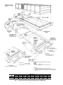
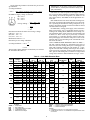
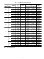
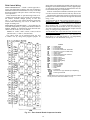
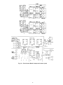
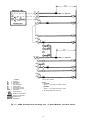
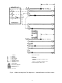
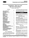
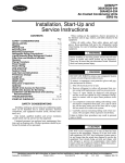
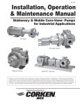
48MA/50ME016-040
Combination Multizone Heating/Cooling Units
Gas, Electric, or Glycol Heat
Installation, Start-Up
and Service Instructions
CONTENTS
Page
SAFETY CONSIDERATIONS . . . . . . . . . . . . . . . . . . . 2
INSTALLATION . . . . . . . . . . . . . . . . . . . . . . . . . . . . . 2-34
General . . . . . . . . . . . . . . . . . . . . . . . . . . . . . . . . . . . . . . 2
Unit Clearances . . . . . . . . . . . . . . . . . . . . . . . . . . . . . . 2
Roof Curb . . . . . . . . . . . . . . . . . . . . . . . . . . . . . . . . . . . 2
Roof Openings . . . . . . . . . . . . . . . . . . . . . . . . . . . . . . . 2
Rigging Unit . . . . . . . . . . . . . . . . . . . . . . . . . . . . . . . . . 5
Unit Positioning . . . . . . . . . . . . . . . . . . . . . . . . . . . . . . 5
Removing Shipping Shields . . . . . . . . . . . . . . . . . . 5
Field-Fabricated Ductwork . . . . . . . . . . . . . . . . . . . . 5
Condensate Drains . . . . . . . . . . . . . . . . . . . . . . . . . . . 9
Gas Piping (48MA) . . . . . . . . . . . . . . . . . . . . . . . . . . . 9
Optional Glycol Connections (50ME) . . . . . . . . . 10
Field Power Supply Wiring . . . . . . . . . . . . . . . . . . 10
• UNIT COMMON FEED MINIMUM CIRCUIT AMPS
Field Control Wiring . . . . . . . . . . . . . . . . . . . . . . . . . 14
• ZONE THERMOSTATS
• ZONE MODULE CONNECTIONS
• ACCESSORY REMOTE CONTROL PANEL
Reheat Humidity Control . . . . . . . . . . . . . . . . . . . . 34
Optional Economizer . . . . . . . . . . . . . . . . . . . . . . . . 34
Optional Exhaust Damper . . . . . . . . . . . . . . . . . . . 34
START-UP . . . . . . . . . . . . . . . . . . . . . . . . . . . . . . . . 34-39
Evaporator Fan . . . . . . . . . . . . . . . . . . . . . . . . . . . . . 34
Compressor Rail Shipping Bolts . . . . . . . . . . . . . 34
Refrigerant Valves . . . . . . . . . . . . . . . . . . . . . . . . . . 34
Zone Module Gas Valves (48MA) . . . . . . . . . . . . . 34
Gas Heat Lighting Procedure (48MA) . . . . . . . . . 35
• TO SHUT OFF GAS HEAT
Intermittant Pilots (48MA) . . . . . . . . . . . . . . . . . . . 35
• ADJUSTMENT
• PRESSURE ADJUSTMENT (NATURAL GAS)
Main Burner Adjustment (48MA) . . . . . . . . . . . . . 36
• ORIFICE ALIGNMENT
• PRIMARY AIR ADJUSTMENT
Outdoor-Air Thermostat Adjustment
(50ME With Electric Heat) . . . . . . . . . . . . . . . . . . 36
• UNITS WITH 2-ELEMENT HEATERS
• UNITS WITH 3-ELEMENT HEATERS
Optional Glycol Heating Coils . . . . . . . . . . . . . . . . 38
Zone Airflow Adjustment . . . . . . . . . . . . . . . . . . . . 38
Sequence of Operation . . . . . . . . . . . . . . . . . . . . . 38
• COOLING
• HEATING (48MA)
• HEATING (50ME WITH ELECTRIC HEAT)
• HEATING (50ME WITH GLYCOL HEATING COILS)
• OUTDOOR-AIR DAMPER
SERVICE . . . . . . . . . . . . . . . . . . . . . . . . . . . . . . . . . . 39-43
Cabinet Panels and Grilles . . . . . . . . . . . . . . . . . . 39
• SIDE PANELS
• TOP PANELS
• HEATER ACCESS PANELS
Cleaning . . . . . . . . . . . . . . . . . . . . . . . . . . . . . . . . . . . . 39
• EVAPORATOR COILS (ZONE COOLING COILS)
AND GLYCOL HEATING COILS
• CONDENSER AND OUTDOOR-AIR COOLING
COILS
• CONDENSATE DRAINS
• INDOOR-AIR FILTERS
• OUTDOOR-AIR INLET SCREENS
• GAS HEATING SECTION
• COMBUSTION AIR FAN
Airflow Switches . . . . . . . . . . . . . . . . . . . . . . . . . . . . 39
• INDOOR AIRFLOW SWITCH (AFS1)
• COMBUSTION AIRFLOW SWITCH (AFS2)
Service Switch . . . . . . . . . . . . . . . . . . . . . . . . . . . . . . 39
Time GuardT Control Circuit . . . . . . . . . . . . . . . . . 39
Capacity Control Pressure Switches (CCP)
(2-Compressor Units Only) . . . . . . . . . . . . . . . . 39
Compressor Oil . . . . . . . . . . . . . . . . . . . . . . . . . . . . . 39
• TO ADD OR REMOVE OIL
Compressor Capacity Control Unloader(s) . . . . 40
• CONTROL SET POINT
• PRESSURE DIFFERENTIAL
Crankcase Heater(s) . . . . . . . . . . . . . . . . . . . . . . . . . 40
Refrigerant Charge . . . . . . . . . . . . . . . . . . . . . . . . . . 40
• NO CHARGE
• LOW CHARGE
Head Pressure Control . . . . . . . . . . . . . . . . . . . . . . 40
• MOTORMASTERt HEAD PRESSURE CONTROL
DEVICE
• FAN CYCLING PRESSURESTAT
Condenser Fans . . . . . . . . . . . . . . . . . . . . . . . . . . . . 41
• ADJUSTMENT
• FAN MOTOR REMOVAL
• LUBRICATION
Evaporator Fans and Motor . . . . . . . . . . . . . . . . . . 41
• MOTOR REMOVAL
• FAN SHAFT BEARING REMOVAL
• FAN SPEED ADJUSTMENT
• PULLEY REMOVAL
• PULLEY ALIGNMENT
• BELT TENSION ADJUSTMENT
• LUBRICATION
Forced-Draft Blower (48MA) . . . . . . . . . . . . . . . . . 42
• LUBRICATION
• AIR SHUTTER ADJUSTMENT
Zone Module Transformers . . . . . . . . . . . . . . . . . . 42
Optional Economizer . . . . . . . . . . . . . . . . . . . . . . . . 42
• THERMOSTAT SETTINGS
• DAMPER POSITION
• OPERATION
Optional Exhaust Damper . . . . . . . . . . . . . . . . . . . 42
Replacement Parts . . . . . . . . . . . . . . . . . . . . . . . . . . 42
START-UP CHECKLIST . . . . . . . . . . . . . . . . . . . . . CL-1
Manufacturer reserves the right to discontinue, or change at any time, specifications or designs without notice and without incurring obligations.
Book 1 1
PC 111
Catalog No. 564-840
Printed in U.S.A.
Form 48MA/50ME-3SI
Pg 1
4-96
Replaces: 48MA/50ME-1SI
Tab 1c 1d
SAFETY CONSIDERATIONS
INSTALLATION
Installation and servicing of air-conditioning equipment
can be hazardous due to system pressure and electrical components. Only trained and qualified service personnel should
install, repair, or service air-conditioning equipment.
Untrained personnel can perform basic maintenance functions of cleaning coils and filters and replacing filters. All
other operations should be performed by trained service personnel. When working on air-conditioning equipment, observe precautions in the literature, tags and labels attached
to the unit, and other safety precautions that may apply.
Follow all safety codes, including ANSI (American
National Standards Institute) Z223.1. Wear safety glasses and
work gloves. Use quenching cloth for unbrazing operations.
Have fire extinguisher available for all brazing operations.
General — Install unit on rooftop, outdoor site only. Install unit, electrical wiring, gas supply line (48MA) and condensate drain lines in accordance with all applicable codes.
Unit Clearances — See Fig. 1 and 2 for service and
airflow clearances. For 48MA gas-fired units, provide not
less than 36-in. clearance to combustibles from top and all
sides. Keep burner end free from any obstruction.
Locate exit terminals of mechanical draft system (48MA
flue outlet) as follows:
• Not less than 12 in. from any opening through which combustion products could enter the building.
• Not less than 2 ft from any adjacent building.
• Not less than 7 ft above grade when unit is adjacent to
public walkways.
Roof Curb — Assemble and install per instructions shipped
with this accessory. Information required to field fabricate a
roof curb and other curb data are shown in Fig. 3-5.
Install field-supplied insulation, cant strips, roofing and
counter flashing as required. Seal all curb joints with mastic
or other suitable roof cement to keep out moisture. Be sure
that run-off pan at compressor end of curb is completely flashed
and sealed.
Seal strip (Fig. 3) is shipped with accessory roof curb. Install as described in the roof curb installation instructions.
The seal strip compresses under unit weight so that an airtight seal and vibration isolation are provided between unit
base and curb.
Before performing service or maintenance operations on
unit, turn off main power switch to unit. Electrical shock
could cause personal injury.
Do not try to light any appliance. Do not touch any electrical switch; do not use any phone in your building.
Immediately call your gas supplier from a neighbor’s
phone. Follow the gas supplier’s instructions. If you cannot reach your gas supplier, call the fire department.
Roof Openings — Except for the compressor and condenser section, roof area under the unit need not be filled in
as the curb-mounted unit encloses this space. Leaving this
roof section open provides ample clearance for ductwork,
piping, and power and control wiring.
If the roof area inside curb is to be filled in so that roof
deck and bottom of base unit can be used as a return-air plenum, any spaces under the curb flanges caused by corrugated roofing or roof irregularities must be sealed to prevent
water seepage. If spaces are not sealed, the negative pressure of return air may draw water under the unit and into the
building structure.
If openings are cut in a finished roof, provide at least 6-in.
space on each of the longer sides of the supply and return air
openings. Due to interference from the roof curb structure,
this additional clearance may not be possible on the short
sides.
Do not store or use gasoline or other flammable vapors
and liquids in the vicinity of the 48MA unit or any other
gas-fired appliance.
Improper installation, adjustment, alteration, service, or
maintenance can cause injury or property damage. Refer to this manual. For assistance or additional information, consult a qualified installer, service agency, or
the gas supplier.
Disconnect gas piping from 48MA unit when leak testing at pressures greater than 0.5 psig. Pressures greater
than 0.5 psig will cause gas valve damage resulting in
a hazardous condition. If gas valve is subjected to pressure greater than 0.5 psig, it must be replaced. When
pressure testing field-supplied gas piping at pressures of
0.5 psig or less, the unit connected to such piping must
be isolated by manually closing the gas valve.
2
CONDENSER SECTION AIRFLOW
CONN — Connection
NOTES:
1. Space required for service and airflow all
around and above unit is 36 inches.
2. For additional information see Fig. 4.
3. Center of gravity is within 6 in. radius of geometric center of unit.
4. Maximum allowable pitch of unit is 1⁄2 in. per
10 ft in any direction.
Certified dimension drawings available on request.
UNIT
48MA
016-030
034,040
A
7- 23⁄4
7-11
B
3-05⁄8
3-915⁄16*
C
17-115⁄16
21- 91⁄16
D
2-215⁄16
4-25⁄8
DIMENSIONS (ft-in.)
E
F
G
13-51⁄2
0- 91⁄16
2-10
13-51⁄2
0-111⁄16
3- 45⁄16
H
7-33⁄16
8-63⁄4
J
0-31⁄8
0-31⁄32
*Overall height; includes 13⁄4-in. for fan guards.
Fig. 1 — Base Unit Physical Data and Dimensions; 48MA Units
3
K
0-31⁄8
0-215⁄16
L
0-31⁄8
0-71⁄4
CONDENSER SECTION AIRFLOW
CONN — Connection
NOTES:
1. Space required for service and airflow all
around and above unit is 36 inches.
2. For additional information see Fig. 5.
3. Center of gravity is within 6 in. radius of geometric center of unit.
4. Maximum allowable pitch of unit is 1⁄2 in. per
10 ft in any direction.
Certified dimension drawings available on request.
UNIT
50ME
016-030
034,040
A
7- 23⁄4
7-11
B
3-09⁄16
3-915⁄16*
C
17-115⁄16
21-91⁄16
DIMENSIONS (ft-in.)
D
E
F
2-215⁄16
13-51⁄2
3-71⁄16
4-25⁄8
13-51⁄2
4-4
G
7-33⁄16
8-63⁄4
H
0-31⁄8
0-215⁄16
*Overall height; includes 13⁄4-in. for fan guards.
Fig. 2 — Base Unit Physical Data and Dimensions; 50ME Units
4
J
0-31⁄8
0-71⁄4
AIRFLOW
*Factory supplied (with accessory roof curb).
†Field supplied (when using accessory roof curb).
NOTE: Dimensions are in inches.
Fig. 3 — Roof Curb Detail
Rigging Unit — Inspect unit for shipping damage, and
Field-Fabricated Ductwork — Supply- and returnair openings are shown in Fig. 4 and 5. To simplify supplyair connection, a zone duct plenum may be field fabricated
as shown in Fig. 7. It is recommended that this plenum be
installed prior to unit positioning.
It is recommended that the unit be supported on blocks
temporarily while the duct plenum is installed, rather than
installing the plenum while the unit is suspended. The duct
plenum may be installed once the unit is located in its final
position, but it is much easier to install the plenum prior to
unit final placement.
Zone supply-air duct openings on the base unit have tab
slot connections similar to those shown in Fig. 7 except that
the end partitions are hemmed. Hem is positioned so that the
1-in. flange at entering end of field-fabricated plenum will
force-fit between hem and adjacent unit frame.
Standard flexible duct connections between duct plenum
and duct system may be used. Follow applicable codes.
Insulate any supply-air ducts passing through unconditioned spaces and cover with a vapor barrier. Separate ducts
with insulation if they run parallel for more than 5 ft. This
will prevent heat transfer between zones.
Install a manual balancing damper in each zone duct to
provide the required zone airflow.
The return-air duct connection consists of 4 sheet metal
flanges as shown in Fig. 1, 2, 4, and 5.
file any damage claim immediately with transportation
company.
Lift unit with cables and spreader bars, using lifting brackets provided (Fig. 1 and 2). Lift one unit at a time, keep unit
upright, and do not drop. Unit weights are given in Table 1.
Unit center of gravity is within 6 in. of unit’s geometric center. Eyebolts may be removed after unit is in final position.
IMPORTANT: Do not drill or punch holes in unit frame
or panels; damage to internal components or wiring
may result.
Unit Positioning — When lowering unit onto roof curb,
do not exceed the out-of-symmetry tolerances given in
Fig. 4 and 5. Be sure unit is level or is pitched within specified tolerances. Units have drains on both sides and may be
pitched to either side.
Removing Shipping Shields (Fig. 6)
1. Remove shield over flue outlet grille (48MA only).
2. Remove shields (sheet metal covers) located in the outdoorair inlet screen tracks behind the louvers. If the screens
are removed for this procedure, be sure to replace them
before replacing the louvered assembly.
5
Table 1 — Physical Data
UNIT 48MA/50ME
Zone Modules (Quantity)
Nominal Cooling Capacity (tons)
OPERATING WEIGHT (lb)
Base Unit 48MA
Base Unit 50ME (with electric heat)
Roof Curb
REFRIGERANT CHARGE — R-22 (lb)
COMPRESSOR
No. 1 Type
Cylinders...Unloaders
No. 2 Type
Cylinders (have no unloaders)
System Oil Charge (pints)
Unloader Settings (psig)
Loads
Unloader No. 2
Unloads
Loads
Unloader No. 1
Unloads
Capacity Steps (%)
CONDENSER FANS
Motor Hp...Rpm...Frame (NEMA)
No. 1
No. 2
No. 3
Nominal Cfm
EVAPORATOR FANS*
Number...Size (in.)
Cfm (Nominal)
Std
Motor Hp...Rpm
Alt
Fan Pulley
Outside Diameter (in.)
Bore (in.)
Std
Fan Belt Number...Size
Alt
Motor Pulley
Std
Outside Diameter (in.)
Alt
Bore (in.)
Std
Resulting Fan Rpm
Alt
Shaft Center Line Distance (in.)
Maximum Fan Rpm
CONDENSER COOLING COIL
Face Area (sq ft)
Corrugated Fins/in. ...Rows
EVAPORATOR COILS (zone)
Number...Face Area (sq ft/ea)
Corrugated Fins/in. ...Rows
HEATING SECTION (48MA)
Rise Range
Total
Input (1000 Btuh)
Each Module
Total
Bonnet Cap.† (1000 Btuh) Each Module
Burner Spud Qty...Size
OPTIONAL HEATING SECTION (50ME Electric)
Electric Heaters
Qty...Elements (each)**
OPTIONAL HEATING SECTION
(50ME Glycol Coil)
Maximum Allowable Inlet Temperature (F)
Maximum Allowable Flow, Each Coil (Gpm)
Solution Mixture
Maximum Allowable Working Pressure (Psig)
Total Internal Volume (Gal)
PRESSURE SWITCHES
Cutout
Low-Pressure (Psig)
Cut-in
Cutout
High-Pressure (Psig)
Cut-in
Indoor Airflow Switch (AFS1)
Factory Setting (cfm)
Adjustment Range (cfm)
INDOOR AIR FILTERS
Standard Qty...Size (in.)
High Efficiency (optional)
Qty...Size (in.)
OUTDOOR AIR FILTERS
Qty...Size (in.)
016
8
15
024
8
20
028
10
25
3395
2995
506
28
3815
3415
506
32
06DE537
6...2
—
—
11
06DE824
6...2
06DA824
6
18
4075
4080
3675
3680
506
506
43
43
Reciprocating Hermetic, 1725 Rpm
06DE537
06DE537
6...2
6...2
06DA824
06DA537
6
6
18
18
Compressor No. 1 Only
71.0 ± 1.5
57.5 ± 2.5
75.0 ± 1.5
62.5 ± 2.5
100,80,60
100,80,60
40,20
40,20
Propeller, Direct Drive
100,67,33
100,83,67
50,33,17
—
16,500
—
15,000
2...15 × 15
6000
5...1725
—
2...15 × 15
8000
71⁄2...1725
—
10.6
13⁄16
1...3V630
—
10.6
13⁄16
1...3V630
—
5.3
—
11⁄8
880
—
18 ± 2.5
1300
6.8
13...2
8...2.12
13...3
432
54
324
40.5
2...38
8...2 or 3
030
10
28
1...1075...56 (Single phase)
1...1140...56 (3 phase)
—
—
15,000
15,000
Centrifugal, Belt Drive
2...15 × 15
2...15 × 15
10,000
10,000
10...1725
10...1725
—
—
034
12
30
040
12
37
5340
4900
630
57
5710
5270
630
66.1
06DE537
6...2
06DA537
6
18
06EE250
4...1
06EA250
4
31
100,83,67
50,33,17
—
—
75.5 ± 1.5
58.0 ± 2.5
100,75,
50,25
1...1140...56 (3 phase)
24,000
23,000
3...15 × 9
12,000
15...1725
20...1725
3...15 × 9
12,000
15...1725
20...1725
8.0
8.0
8.0
13⁄16
13⁄16
111⁄16
2...3V560
2...3V560
2...3V630
—
—
3...3V670
Factory Installed
6.0
5.0
5.0
5.0
—
—
—
6.0
3
3
3
1 ⁄8
1 ⁄8
1 ⁄8
15⁄8
995
1095
1095
1095
—
—
—
1320
18 ± 2.5
18 ± 2.5
18 ± 2.5
21 ± 2.5
1300
1300
1300
1550
Thermostatic Expansion Valve, Hot Gas Bypass
6.8
6.8
6.8
10.2
13...2
13...2
13...2
13...2
Solenoid Valve and Capillary Tube for each
8...2.12
10...2.12
10...2.12
12...2.01
13...3
13...3
13...3
12...3
One Heat Assembly in Each Zone Module
25 F to 55 F at 0.75 in. wg ESP
432
540
540
648
54
54
54
54
324
405
405
486
40.5
40.5
40.5
40.5
2...38
2...38
2...38
2...38
8.0
111⁄16
2...3V630
3...3V670
Nichrome, Open-Wire Resistance Element in Each Zone Module
8...2 or 3
10...2 or 3
10...2 or 3
12...2 or 3
5.0
6.0
15⁄8
1095
1320
21 ± 2.5
1550
10.2
13...3
12...2.01
15...3
648
54
486
40.5
2...38
12...2 or 3
One Heating Coil in Each Zone Module
200
6
20% Glycol
30
2.61
2.61
3.15
3.15
3.76
3.76
29 ± 5
39 ± 5
400 ± 5
300 ± 5
6000
4000-6000
9000
6000-9000
12...20 × 25 × 2
12...20 × 25 × 2 (36.5% Efficient)
2...20 × 25 × 1
2...32 × 35 × 1
LEGEND
ESP
— External Static Pressure
NEMA — National Electrical Manufacturers Association
*Standard unit shipped with standard motor, pulley, and belt(s); alternate unit shipped with alternate motor, pulley, and belt(s).
†The heating efficiency rating is a product thermal efficiency rating determined under continuous operating conditions independent of any installed system.
**See Field Power Supply Wiring section on page 10 and Table 4 for details.
6
EVAPORATOR (ZONE MODULE) AIRFLOW
CONN — Connection
*Not used on 48MA016,024 (8 zone module units).
NOTES:
1. For additional information, see Table 1 and Fig. 1.
2. Maximum allowable unit pitch is 1⁄2 in. per 10 ft in any direction.
3. Remove shipping brace before assembling curb section (location
shown).
UNIT
48MA
016-030
034,040
A
18-21⁄8
21-97⁄8
B
7- 3
7-113⁄4
C
11-9
14-13⁄4
DIMENSIONS (ft-in.)
D
E
F
5-61⁄4
7-27⁄8
1-109⁄16
6-77⁄16
8-43⁄16
2- 91⁄8
G
2-29⁄16
3-1
H
6-03⁄8
6-81⁄2
Fig. 4 — Roof Curb Physical Data and Dimensions; 48MA Units
7
J
0- 71⁄2
0-105⁄16
EVAPORATOR (ZONE MODULE) AIRFLOW
CONN — Connection
*Not used on 50ME016,024 (8 zone module units).
END DETAIL
(034,044 12-ZONE MODULES)
NOTES:
1. For additional information, see Table 1 and Fig. 2.
2. Maximum allowable unit pitch is 1⁄2 in. per 10 ft in any direction.
3. Remove shipping brace before assembling curb section (location
shown).
UNIT
50ME
016-030
034,040
A
18-21⁄8
21-97⁄8
B
7- 3
7-113⁄4
C
11-9
14-13⁄4
DIMENSIONS (ft-in.)
D
E
F
5-61⁄4
7-27⁄8
1-109⁄16
6-77⁄16
8-43⁄16
2- 91⁄8
G
2-29⁄16
3-1
H
6-03⁄8
6-81⁄2
Fig. 5 — Roof Curb Physical Data and Dimensions; 50ME Units
8
J
0- 71⁄2
0-105⁄16
Do not interconnect drains. Make each trap a minimum of
4 in. deep. Insulate trap against freeze-up or use flexible
material.
Condensate Drains — Pipe nipples covered with foam
rubber insulation are shipped in unit return air filter section
(6 nipples in units 48MA, 4 nipples in units 50ME). Install
a nipple in each drain connection on both sides of unit. See
Fig. 1 and 2 for drain locations. Be sure foam rubber seals
space between nipple and base rail opening to prevent rain
leaks.
Connect a drain line to drain connection under outdoor air
inlet grilles on both sides of unit. These drains need not be
trapped.
Install a trapped drain line on remaining connections on
lowest side of unit depending on unit pitch. If unit is level,
a trapped drain may be installed at each connection if desired. Cap or plug unused connections on high side of unit
to prevent airflow between unit interior and outdoors.
OUTDOOR AIR INLET
(ONE ON EACH SIDE OF UNIT)
SHIPPING SHIELD
(BEHIND LOUVERS)
Gas Piping (48MA) — Unit is equipped for use with
type of gas shown on nameplate. Refer to latest edition of
ANSI Z223.1. Unit main gas connection and alternate gas
connection locations are shown in Fig. 1, 4, and 8. Do not
use gas supply pipe smaller than unit gas connection. Maximum allowable natural gas supply pressure is 10.0 in. wg;
minimum allowable natural gas supply pressure for full rate
input is 5.0 in. wg.
Pitch pipe 1⁄4 in. per 15 ft. Pitch all horizontal pipe runs
upward to risers and from risers upward to meter. Install a
dirt and moisture pocket (drip leg) at each section of vertical
pipe run. Use only ground joint unions to ensure leakfree
joints. Use only pipe joint compounds that are resistant to
the action of liquefied petroleum gases.
FLUE OUTLET
COVER
(48MA ONLY)
Fig. 6 — Shipping Shield Locations
(016-030 Units Shown)
DIMENSIONS (in.)
UNIT
48MA,50ME
A*
B*
016,024
028,030
034,040
75⁄8
75⁄8
75⁄8
73⁄4
75⁄16
53⁄4
*Typical; both ends.
NOTE: Dimension to suit job requirements. Twelve inches will bring
duct plenum to bottom of roof curb.
Fig. 7 — Field-Fabricated Zone Duct Plenum Detail
9
All units have a main power supply terminal board in the
power and condensing control box. The electric resistance
heater power supply terminal board(s) (if unit is so equipped)
on 50ME units is located in the heater control box at front
of unit. See Fig. 2, 5, and 9.
All terminal boards are suitable for use with copper or
aluminum wire.
Connect electrical conduit (a threaded pipe nipple) shipped
with unit to threaded fitting in roof curb and bottom of main
power and condensing section control box. Route main power
wires through conduit to terminal board in box as shown on
unit label wiring diagram and in Fig. 9.
When installing 48MA,50ME040 units with optional 20-hp
motor, the electrical conduit interconnecting the curb and control box power wire openings will not accommodate aluminum wire of the size that may be required. If aluminum wire
cannot be accommodated, an external transition box and short
lengths of no. 300 kcmil, 75 C copper wire from the transition box to the unit main power connection are
recommended.
Voltage to compressor terminals during compressor operation must be within voltage range indicated on unit nameplate. Phases must be balanced within 2%.
*Shutoff valve not used except where required by code.
Properly cap any gas connection not being used.
Fig. 8 — Suggested Gas Piping (48MA)
Unit has factory-installed gas shutoff valves. Install gas
shutoff valve external to unit if required by code (Fig. 8).
After piping is complete, pressurize gas line and check for
leaks with soap and water solution.
Do not use an open flame when checking for gas leaks.
Optional Glycol Connections (50ME) — Each zone
module has its own glycol heating coil and 115-v solenoid
valve. Heating coils are connected in parallel to common supply and return manifolds. Supply manifolds are equipped with
bleed cocks. Supply and return connections are shown in
Fig. 2 and 5. Unit does not have internal pressure relief for
part-load operation. Maximum allowable system working pressure is 30 psig. Unit ratings are based on 20% glycol solutions. Install solution supply apparatus in accordance with
application requirements, and mix glycol solution percentage in accordance with glycol manufacturer’s recommendations. Freeze-up protection is not factory installed.
Field Power Supply Wiring — When installed, unit
must be electrically grounded in accordance with local codes
or, in the absence of local codes, with the National Electrical
Code (NEC).
Unit has a circuit breaker for each compressor, each fan
motor, and for each 50ME electric resistance heater assembly (if unit is so equipped). If required by local code, provide an additional disconnect switch in accordance with code
being followed.
LEGEND
EQUIP — Equipment
GND
— Ground
TB
— Terminal Board
*208/230 v units only.
Fig. 9 — Field Power Supply Details
10
Use the following formula to determine the percent voltage imbalance.
% Voltage Imbalance:
max voltage deviation from average voltage
= 100 ×
average voltage
EXAMPLE: Supply voltage is 460-3-60.
AB = 452 v
BC = 464 v
AC = 455 v
452 + 464 + 455
Average Voltage =
3
1371
=
3
= 457
Determine maximum deviation from average voltage.
(AB) 457 − 452 = 5 v
(BC) 464 − 457 = 7 v
(AC) 457 − 455 = 2 v
Maximum deviation is 7 v.
Determine percent voltage imbalance:
7
% Voltage Imbalance = 100 x
457
= 1.53%
This amount of phase imbalance is satisfactory as it is below
the maximum allowable 2%.
IMPORTANT: If the supply voltage phase imbalance
is more than 2%, contact your local electric utility company immediately.
Unit failure as a result of operation on improper line voltage or excessive phase imbalance constitutes abuse and may
cause damage to electrical components. See Tables 2-5 for
unit, electric heater, and 50ME electrical application electrical data.
Each 50ME electric heat unit is fitted with a heating lockout circuit (if equipped with optional heat). If any zone module is operating on mechanical cooling (compressor is operating), the heating element in each zone module is locked
out and cannot be energized.
On 50ME units, cooling power supply wires and electric
heater power supply wires (if applicable) must be sized according to the cooling MCA (Minimum Circuit Amps) values and heating MCA values shown on unit nameplate and
in Tables 3-5. These wires may be powered by a common
power supply (i.e., a pull-box junction), if desired. The common power supply wires from the main power source to the
junction must be sized according to the common MCA values shown in Table 5.
UNIT COMMON FEED MINIMUM CIRCUIT AMPS —
The unit common feed MCA is calculated on the basis of
either: the sum of the cooling MCA plus 1⁄2 heating MCA on
units with 2 heating elements per zone module (or 2⁄3 heating MCA on units with 3 heating elements per zone module)
or the sum of the evaporator fan motor full load amps, per
NEC, plus the full heating MCA, whichever is larger. Field
wiring must conform to NEC limitations for Type T wire.
Table 2 — Unit 48MA Electrical Data
UNIT
48MA
COMP
NO. 1
RLA LRA
63.6 266
28.6 120
22.8
96
44.4 170
19.9
77
15.7
62
63.6 266
28.6 120
22.8
96
63.6 266
28.6 120
22.8
96
COMP
NO. 2
RLA LRA
208/230
460
575
208/230
460
575
208/230
460
575
208/230
460
575
VOLTAGE
RANGE
Min Max
187
254
414
508
518
632
187
254
414
508
518
632
187
254
414
508
518
632
187
254
414
508
518
632
208/230
187
254
63.6
460
414
508
575
518
208/230
Voltage
(3 Ph, 60 Hz)
016
024
028
030
034
040
—
—
44.4
19.9
15.7
44.4
19.9
15.7
63.6
28.6
22.8
170
77
62
170
77
62
266
120
96
266
63.6
266
28.6
120
28.6
120
632
22.8
96
22.8
187
254
80.0
345
460
414
508
38.5
575
518
632
31.4
No. 1
6.2
6.2
6.2
6.2
—
—
—
—
—
No. 3
COMBUSTION
FAN MOTOR
FLA
Hp
—
1.8
5
—
1.8
7.5
—
1.8
10
—
1.8
10
6.6
6.6
3.0
3.0
96
2.4
2.4
80.0
345
6.6
6.6
150
38.5
150
3.0
3.0
120
31.4
120
2.4
2.4
6.2
6.2
LEGEND
COMP
FLA
IFM
LRA
MCA
OFM
FLA
No. 2
6.6
3.0
2.4
6.6
3.0
2.4
6.6
3.0
2.4
6.6
3.0
2.4
1.8
1.8
IFM
15
20
15
20
15
20
15
20
15
20
15
20
FLA
16.2
6.6
5.6
24.2
11.0
9.0
30.8
13.0
10.5
30.8
13.0
10.5
46.2
61.0
21.0
26.6
16.0
21.3
46.2
61.0
21.0
27.0
16.0
21.3
POWER
SUPPLY
MCA MOCP
109.6
125
49.8
60
39.8
45
137.5
150
62.2
70
49.4
60
168.1
200
76.1
90
60.4
70
187.3
200
84.5
100
67.5
90
210.8
225
224.6
250
94.5
100
100.5
125
75.6
90
80.6
100
247.7
300
261.5
300
116.7
150
122.7
150
95
125
100
125
MOCP — Maximum Overcurrent Protection
OFM
— Outdoor (Condenser) Fan Motor
RLA
— Rated Load Amps
NOTES:
1. Combustion air fan is a 115-1-60 motor on all units.
2. Condenser fan motor no. 1 is a 208/230-1-60 speed control motor
on all units.
Compressor
Full Load Amps
Indoor (Evaporator) Fan Motor
Locked Rotor Amps
Minimum Circuit Amps
11
Table 3 — Unit 50ME Electrical Data
UNIT
50ME
016
024
028
030
034
040
COMP
FLA
IFM
LRA
MCA
MOCP
OFM
RLA
COMP
NO. 1
RLA
LRA
63.6
266
28.6
120
22.8
96
44.4
170
19.9
77
15.7
62
63.6
266
28.6
120
22.8
96
63.6
266
28.6
120
22.8
96
COMP
NO. 2
RLA
LRA
208/230
460
575
208/230
460
575
208/230
460
575
208/230
460
575
VOLTAGE
RANGE
Min
Max
187
254
414
508
518
632
187
254
414
508
518
632
187
254
414
508
518
632
187
254
414
508
518
632
208/230
187
254
63.6
460
414
508
575
518
208/230
VOLTAGE
(3 Ph, 60 Hz)
—
—
—
—
—
—
—
—
—
—
44.4
19.9
15.7
44.4
19.9
15.7
63.6
28.6
22.8
170
77
62
170
77
62
266
120
96
266
63.6
266
28.6
120
28.6
120
632
22.8
96
22.8
187
254
80.0
345
460
414
508
39.3
575
518
632
31.4
No. 1
6.2
6.2
6.2
6.2
OFM
FLA
No. 2
6.6
3.0
2.4
6.6
3.0
2.4
6.6
3.0
2.4
6.6
3.0
2.4
IFM
No. 3
Hp
—
5
—
7.5
—
10
—
10
6.6
6.6
3.0
3.0
96
2.4
2.4
80.0
345
6.6
6.6
150
39.3
150
3.0
3.0
120
31.4
120
2.4
2.4
LEGEND
Compressor
Full Load Amps
Indoor (Evaporator) Fan Motor
Locked Rotor Amps
Minimum Circuit Amps
Maximum Overcurrent Protection
Outdoor (Condenser) Fan Motor
Rated Load Amps
6.2
6.2
15
20
15
20
15
20
15
20
15
20
15
20
FLA
16.2
6.6
5.6
24.2
11.0
9.0
30.8
13.0
10.5
30.8
13.0
10.5
46.0
61.0
19.8
26.6
16.0
21.3
46.2
61.0
19.8
26.6
16.0
21.3
POWER
SUPPLY
MCA
MOCP
109.6
125
49.5
60
39.6
45
138.0
150
61.9
70
49.2
60
168.9
200
75.8
90
60.2
70
188.0
200
84.5
100
67.3
90
210.8
225
224.6
250
94.5
100
100.5
125
75.6
90
80.6
100
247.7
300
261.5
300
118.5
150
124.5
150
95
125
100
125
NOTE: Condenser fan motor no. 1 is a 208/230-1-60 speed control
motor on all units.
Table 4 — Electric Resistance Heater Data
UNIT
50ME
NOMINAL
VOLTAGE
(3 Ph, 60 Hz)
208/230
016,024
460
575
208/230
028,030
460
575
208/230
034,040
460
575
ELECTRIC
HEAT kW
(Unit Total)
43/ 53
57/ 70
87/106
53
70
106
106
54/ 66
72/ 88
108/132
66
88
132
132
65/ 79
87/106
129/158
79
106
158
158
HEATING ELEMENTS
PER ZONE MODULE
FLA PER
HEATING ELEMENT
MCA
(Each Circuit)
MOCP
(Each Circuit)
2
2
3
2
2
3
3
2
2
3
2
2
3
3
2
2
3
2
2
3
3
13.0/14.4
17.3/19.2
17.3/19.2
7.2
9.6
9.6
7.7
13.0/14.4
17.3/19.2
17.3/19.2
7.2
9.6
9.6
7.7
13.0/14.4
17.3/19.2
17.3/19.2
7.2
9.6
9.6
7.7
150/166
200/221
150/166
83
111
166
133
188/207
250/276
188/207
103
138
207
166
225/249
150/165
225/249
124
166
249
199
175/175
225/225
175/175
90
125
175
150
200/225
275/300
200/225
110
150
225
175
250/250
175/175
250/250
125
175
250
200
LEGEND
FLA
— Full Load Amps
MCA — Minimum Circuit Amps
MOCP — Maximum Overcurrent Protection
NOTES:
1. Heaters are rated at 230 v, 460 v, and 575 v.
2. Terminal boards provided for heater power wire connections are
suitable for use with copper or aluminum wire.
12
Table 5 — Unit 50ME Electrical Application Data
UNIT
50ME
Size
IFM
Hp
NOMINAL
VOLTAGE
208/230
016
5
460
575
208/230
024
7.5
460
575
208/230
028
10
460
575
208/230
030
10
460
575
208/230
15
460
575
034
208/230
20
460
575
208/230
15
460
575
040
208/230
20
460
575
kW
(Unit
Total)
43/ 53
57/ 70
87/106
53
70
106
106
43/ 53
57/ 70
87/106
53
70
106
106
54/ 66
72/ 88
108/132
66
88
132
132
54/ 66
72/ 88
108/132
66
88
132
132
65/ 79
87/106
129/158
79
106
158
158
65/ 79
87/106
129/158
79
106
158
158
65/ 79
87/106
129/158
79
106
158
158
65/ 79
87/106
129/158
79
106
158
158
MCA
Heating
Circuit
Cooling
109.8/109.8
49.5
39.6
138.0/138.0
61.9
49.2
168.9
75.8
60.2
188.0
84.5
67.3
210.8
94.5
75.6
224.6
100.5
80.6
247.7
116.7
95.0
261.5
122.7
100.0
LEGEND
IFM — Indoor (Evaporator) Fan Motor
MCA — Minimum Circuit Amps
13
1
2
150.0/165.6
200.0/220.9
150.0/165.8
82.9
110.5
165.8
132.5
150.0/160.6
200.0/220.9
150.0/165.8
82.9
110.5
165.8
132.5
188.0/207.1
250.0/276.1
188.0/207.1
102.8
138.0
207.1
165.6
188.0/207.1
250.0/276.1
188.0/207.1
102.8
138.0
207.1
165.6
225.0/248.5
150.0/165.6
225.0/248.5
124.3
165.1
248.5
198.8
225.0/248.5
150.0/165.1
225.0/248.5
124.3
165.6
248.5
198.8
225.0/248.5
150.0/165.1
225.0/248.5
124.3
165.6
248.5
198.8
225.0/248.5
150.0/165.1
225.0/248.5
124.3
165.6
248.5
198.8
—
—
150.0/165.8
—
—
—
—
150.0/165.8
—
—
—
—
188.0/207.1
—
—
—
—
188.0/207.1
—
—
—
150.0/165.1
225.0/248.5
—
—
—
150.0/165.1
225.0/248.5
—
—
—
150.0/165.1
225.0/248.5
—
—
—
150.0/165.1
225.0/248.5
—
—
Unit
Common
Feed
184.8/192.6
216.7/237.6
316.7/348.3
90.9
117.1
172.4
138.1
213.0/220.8
238.0/248.5
342.2/359.0
103.4
121.5
176.8
141.5
262.9/272.5
293.9/307.0
419.6/445.0
127.2
151.0
220.1
176.1
282.0/291.6
313.0/326.0
438.7/464.0
135.9
153.5
222.6
177.7
323.3/335.1
360.8/376.4
510.9/543.2
156.7
185.4
268.3
214.8
337.1/348.9
374.6/391.2
524.6/558.0
162.7
192.2
275.1
220.1
360.2/372.0
397.7/412.8
547.7/579.0
178.9
199.5
282.4
227.5
374.0/385.8
411.5/426.6
561.5/592.8
148.9
205.5
288.4
232.5
quick-connect type multiplexing terminals. This prevents overloading the nest control transformers. Factory-supplied jumpers with quick-connect terminals are shipped in the zone control and thermostat panel compartment.
Under no circumstances shall the transformer power from
one Class II circuit be interconnected with any other circuit.
Thermostat heat anticipator settings are indicated for each
permitted zone module connection arrangement illustrated
in Fig. 11-28.
To Join Modules of the Same Nest Into the Same Zone (i.e.,
modules no. 1 and 2) — Install field-supplied jumpers on
thermostat connections (screw terminals) Y to Y and W2 to
W2 as shown in Fig. 11. Connect thermostat wires to terminal connections of first module in zone (for consistency).
Two-stage cooling may be obtained in this example as shown
in Fig. 12 (using a 2-stage thermostat).
To Join Modules Not of the Same Nest Into the Same Zone
(i.e., modules no. 2 and 3) — Install the factory-supplied jumpers on quick-connect terminals 6 to 1, 7 to 2, and 8 to 3 as
shown in Fig. 13. Note that module no. 1 is independently
controlled by its own thermostat (in Fig. 13).
Field Control Wiring
ZONE THERMOSTATS — Install a Carrier approved accessory zone thermostat assembly in each zone according to
installation instructions included in the accessory. Locate each
thermostat assembly in the space where it will sense average
zone temperature.
Route thermostat cable or equivalent single leads of no.
18 AWG (American Wire Gage) colored wire from thermostat subbase terminals through opening on base unit
(Fig. 1, 2, 4, and 5) to low-voltage thermostat connections
on zone control board (Fig. 10). Use no. 16 AWG wire for
lengths exceeding 50 ft.
ZONE MODULE CONNECTIONS — Any module may be
controlled independently or jointly with another module or
modules. Modules are combined into nests that form individual Class II circuits (40 va) as follows:
Modules no. 1 and 2, 3 and 4, 5 and 6, 7 and 8, 9 and 10
(028-040 units), 11 and 12 (034,040 units).
The control signal can be transferred from one nest
to another nest by using factory-supplied jumpers on
AFS
CR
ECR
ECT
GV
HC
HR
IFC
LLS
MC
MCR
MH
MHR
MU
MUR
NC
NO
NS
SW
TRAN
—
—
—
—
—
—
—
—
—
—
—
—
—
—
—
—
—
—
—
—
LEGEND
Airflow Switch
Control Relay
Economizer Relay
Economizer Outdoor-Air Thermostat
Gas Valve (not used on 50ME units)
Heater Contactor
Heater Relay
Indoor (Evaporator) Fan Contactor
Liquid Line Solenoid
Master Cooling
Master Cooling Relay
Master Heating
Master Heating Relay
Master Unit
Master Unit Relay
Normally Closed
Normally Open
Night Setback
Switch
Transformer
Quick-Connect Type Terminals (for multiplexing)
Screw-Type Terminals
NOTE: Twelve-zone unit shown. Eight-zone units have modules
1-8 only. Ten-zone units have modules 1-10 only.
Fig. 10 — Zone Control Board Component Location
14
Fig. 10 — Zone Control Board Component Location (cont)
15
C
CR
GV
HA
HR
TC
TH
TRAN
—
—
—
—
—
—
—
—
LEGEND
Contactor
Control Relay
Gas Valve
Heat Anticipator
Heating Relay
Thermostat, Cooling
Thermostat, Heating
Transformer
Screw Terminal
*One for each module.
NOTES:
1. COOLING
Stage 1 — First stage of modules 1 and 2
HEATING
Stage 1 — First stage of modules 1 and 2
2. Set heat anticipator (HA1) at .26.
Quick-Connect Terminal
Factory Control Wires
Printed Circuit
Field Wiring
Fig. 11 — 48MA; One-Stage Heat, One-Stage Cool — 2 Nested Modules, Joint Zone Control
16
C
CR
GV
HA
HR
TC
TH
TRAN
—
—
—
—
—
—
—
—
LEGEND
Contactor
Control Relay
Gas Valve
Heat Anticipator
Heating Relay
Thermostat, Cooling
Thermostat, Heating
Transformer
Screw Terminal
*One for each module.
NOTES:
1. COOLING
Stage 1 — First stage of modules 1 and 2
HEATING
Stage 1 — First stage of modules 1 and 2
2. Set heat anticipator (HA1) at .26.
Quick-Connect Terminal
Factory Control Wires
Printed Circuit
Field Wiring
Fig. 12 — 48MA; One-Stage Heat, Two-Stage Cool — 2 Nested Modules, Joint Zone Control
17
C
CR
GV
HA
HR
TC
TH
TRAN
—
—
—
—
—
—
—
—
LEGEND
Contactor
Control Relay
Gas Valve
Heat Anticipator
Heating Relay
Thermostat, Cooling
Thermostat, Heating
Transformer
Screw Terminal
*One for each module.
NOTES:
1. COOLING
Stage 1 — First stage of modules 1, 2, and 3
HEATING
Stage 1 — First stage of modules 1, 2, and 3
2. Set heat anticipators (HA1) at .13.
Quick-Connect Terminal
Factory Control Wires
Printed Circuit
Field Wiring
Fig. 13 — 48MA; One-Stage Heat, One-Stage Cool — One Independent Module, 2 Joint Modules Zone Control
18
C
CR
GV
HA
HR
TC
TH
TRAN
—
—
—
—
—
—
—
—
LEGEND
Contactor
Control Relay
Gas Valve
Heat Anticipator
Heating Relay
Thermostat, Cooling
Thermostat, Heating
Transformer
*One for each module.
Screw Terminal
2. Set heat anticipators (HA1) at .13.
NOTES:
1. COOLING
Stage 1 — First stage of modules 1, 2, and 3
Stage 2 — Second stage of modules 2 and 3
HEATING
Stage 1 — First stage of modules 1, 2, and 3
Quick-Connect Terminal
Factory Control Wires
Printed Circuit
Field Wiring
Fig. 14 — 48MA; One-Stage Heat, One-Stage Cool; One-Stage Heat, Two-Stage Cool Combination
19
LEGEND
C
CR
GV
HA
HR
TC
TH
TRAN
—
—
—
—
—
—
—
—
Contactor
Control Relay
Gas Valve
Heat Anticipator
Heating Relay
Thermostat, Cooling
Thermostat, Heating
Transformer
Screw Terminal
*One for each module.
NOTES:
1. COOLING
Stage 1 — First stage of modules 1, 2, 3, and 4
HEATING
Stage 1 — First stage of modules 1, 2, 3, and 4
2. Set heat anticipator (HA1) at .26.
Quick-Connect Terminal
Factory Control Wires
Printed Circuit
Field Wiring
Fig. 15 — 48MA; One-Stage Heat, One-Stage Cool — 4 Module Joint Zone Control
20
LEGEND
C
CR
GV
HA
HR
TC
TH
TRAN
—
—
—
—
—
—
—
—
Contactor
Control Relay
Gas Valve
Heat Anticipator
Heating Relay
Thermostat, Cooling
Thermostat, Heating
Transformer
Screw Terminal
*One for each module.
NOTES:
1. COOLING
Stage 1 — First stage of modules 1, 2, 3, and 4
HEATING
Stage 1 — First stage of modules 1, 2, 3, and 4
2. Set heat anticipators (HA1) at .13.
Quick-Connect Terminal
Factory Control Wires
Printed Circuit
Field Wiring
Fig. 16 — 48MA; One-Stage Heat, One-Stage Cool — One Independent Module, 3 Joint Modules Zone Control
21
LEGEND
C
CR
GV
HA
HR
TC
TH
TRAN
—
—
—
—
—
—
—
—
Contactor
Control Relay
Gas Valve
Heat Anticipator
Heating Relay
Thermostat, Cooling
Thermostat, Heating
Transformer
Screw Terminal
*One for each module.
NOTES:
1. COOLING
Stage 1 — Modules 1 and 3
Stage 2 — Modules 2 and 4
HEATING
Stage 1 — First stage of modules 1, 2, 3, and 4
2. Set heat anticipator (HA1) at .26.
Quick-Connect Terminal
Factory Control Wires
Printed Circuit
Field Wiring
Fig. 17 — 48MA; One-Stage Heat, Two-Stage Cool — 4 Module Joint Zone Control
22
C
CR
GV
HA
HR
TC
TH
TRAN
—
—
—
—
—
—
—
—
LEGEND
Contactor
Control Relay
Gas Valve
Heat Anticipator
Heating Relay
Thermostat, Cooling
Thermostat, Heating
Transformer
Screw Terminal
Quick-Connect Terminal
Factory Control Wires
Printed Circuit
Field Wiring
*One for each module.
NOTES:
1. COOLING
Stage 1 — Module 3
Stage 2 — Module 2 and 4
If thermostat wires are interchanged, the reverse may be
obtained.
HEATING
Stage 1 — First stage of modules 2, 3, and 4
2. Set heat anticipator (HA1) at .13.
Fig. 18 — 48MA; One-Stage Heat, Two-Stage Cool — 3 Module Joint Zone Control
23
C
CR
GV
HA
HR
TC
TH
TRAN
—
—
—
—
—
—
—
—
LEGEND
Contactor
Control Relay
Gas Valve
Heat Anticipator
Heating Relay
Thermostat, Cooling
Thermostat, Heating
Transformer
Screw Terminal
*One for each module.
NOTES:
1. COOLING
Stage 1 — First stage of modules 1, 2, 3, and 4
HEATING
Stage 1 — First stage of modules 1, 2, 3, and 4
2. Set heat anticipators (HA1) as follows:
MODULE(S)
1, 3
2
4
Quick-Connect Terminal
Factory Control Wires
Printed Circuit
Field Wiring
SETTING
.26
.13
.13
Fig. 19 — 48MA; One-Stage Heat, One-Stage Cool — 2 Independent Modules, 2 Joint Modules Zone Control
24
C
CR
GV
HA
HR
TC
TH
TRAN
—
—
—
—
—
—
—
—
LEGEND
Contactor
Control Relay
Gas Valve
Heat Anticipator
Heating Relay
Thermostat, Cooling
Thermostat, Heating
Transformer
*One for each module.
Screw Terminal
2. Set heat anticipator 1 (HA1) at .26, and set heat anticipator 2 (HA2)
at 1.14.
Quick-Connect Terminal
Factory Control Wires
Printed Circuit
Field Wiring
NOTES:
1. COOLING
Stage 1 — First stage of modules 1 and 2
HEATING
Stage 1 — First stage of modules 1 and 2
Stage 2 — Second stage of modules 1 and 2
Fig. 20 — 50ME; Two-Stage Heat, One-Stage Cool — 2 Modules, Joint Zone Control
25
C
CR
GV
HA
HR
TC
TH
TRAN
—
—
—
—
—
—
—
—
LEGEND
Contactor
Control Relay
Gas Valve
Heat Anticipator
Heating Relay
Thermostat, Cooling
Thermostat, Heating
Transformer
Screw Terminal
Quick-Connect Terminal
Factory Control Wires
Printed Circuit
Field Wiring
*One for each module.
NOTES:
1. COOLING
Stage 1 — First stage of modules 1 and 2
Stage 2 — Second stage of modules 1 and 2
HEATING
Stage 1 — First stage of modules 1 and 2
Stage 2 — Second stage of modules 1 and 2
2. Set heat anticipator 1 (HA1) at .26, and set heat anticipator 2 (HA2)
at 1.14.
Fig. 21 — 50ME; Two-Stage Heat, Two-Stage Cool — 2 Modules, Joint Zone Control
26
C
CR
GV
HA
HR
TC
TH
TRAN
—
—
—
—
—
—
—
—
LEGEND
Contactor
Control Relay
Gas Valve
Heat Anticipator
Heating Relay
Thermostat, Cooling
Thermostat, Heating
Transformer
*One for each module.
Screw Terminal
2. Set heat anticipator 1 (HA1) at .13, and set heat anticipator 2 (HA2)
at .57 (both thermostats).
Quick-Connect Terminal
Factory Control Wires
Printed Circuit
Field Wiring
NOTES:
1. COOLING
Stage 1 — First stage of modules 1, 2, and 3
HEATING
Stage 1 — First stage of modules 1, 2, and 3
Stage 2 — Second stage of modules 1, 2, and 3
Fig. 22 — 50ME; Two-Stage Heat, One-Stage Cool — One Independent Module, 2 Joint Modules Zone Control
27
LEGEND
C
CR
GV
HA
HR
TC
TH
TRAN
—
—
—
—
—
—
—
—
Contactor
Control Relay
Gas Valve
Heat Anticipator
Heating Relay
Thermostat, Cooling
Thermostat, Heating
Transformer
Screw Terminal
Quick-Connect Terminal
Factory Control Wires
Printed Circuit
Field Wiring
*One for each module.
NOTES:
1. COOLING
Stage 1 — First stage of modules 1, 2, and 3
Stage 2 — Second stage of modules 2 and 3
HEATING
Stage 1 — First stage of modules 1, 2, and 3
Stage 2 — Second stage of modules 1, 2, and 3
2. Set heat anticipator 1 (HA1) at .13, and set heat anticipator 2 (HA2)
at .57 (both thermostats).
Fig. 23 — 50ME; Two-Stage Heat, One-Stage Cool; Two-Stage Heat, Two-Stage Cool Combination
28
LEGEND
C
CR
GV
HA
HR
TC
TH
TRAN
—
—
—
—
—
—
—
—
Contactor
Control Relay
Gas Valve
Heat Anticipator
Heating Relay
Thermostat, Cooling
Thermostat, Heating
Transformer
Screw Terminal
Quick-Connect Terminal
Factory Control Wires
Printed Circuit
Field Wiring
*One for each module.
NOTES:
1. COOLING
Stage 1 — First stage of modules 1, 2, 3, and 4
HEATING
Stage 1 — First stage of modules 1, 2, 3, and 4
Stage 2 — Second stage of modules 1, 2, 3, and 4
2. Set heat anticipator 1 (HA1) at .26, and set heat anticipator 2 (HA2)
at 1.14.
Fig. 24 — 50ME; Two-Stage Heat, One-Stage Cool — 4 Module Joint Control
29
C
CR
GV
HA
HR
TC
TH
TRAN
—
—
—
—
—
—
—
—
LEGEND
Contactor
Control Relay
Gas Valve
Heat Anticipator
Heating Relay
Thermostat, Cooling
Thermostat, Heating
Transformer
*One for each module.
Screw Terminal
2. Set heat anticipator 1 (HA1) at .13, and set heat anticipator 2 (HA2)
at .57 (both thermostats).
Quick-Connect Terminal
Factory Control Wires
Printed Circuit
Field Wiring
NOTES:
1. COOLING
Stage 1 — First stage of modules 1, 2, 3, and 4
HEATING
Stage 1 — First stage of modules 1, 2, 3, and 4
Stage 2 — Second stage of modules 1, 2, 3, and 4
Fig. 25 — 50ME; Two-Stage Heat, One-Stage Cool — One Independent Module, 3 Joint Modules Zone Control
30
C
CR
GV
HA
HR
TC
TH
TRAN
—
—
—
—
—
—
—
—
LEGEND
Contactor
Control Relay
Gas Valve
Heat Anticipator
Heating Relay
Thermostat, Cooling
Thermostat, Heating
Transformer
Screw Terminal
Quick-Connect Terminal
Factory Control Wires
Printed Circuit
Field Wiring
*One for each module.
NOTES:
1. COOLING
Stage 1 —
Stage 2 —
HEATING
Stage 1 —
Stage 2 —
Modules 1 and 3
Modules 2 and 4
First stage of modules 1, 2, 3, and 4
Second stage of modules 1, 2, 3, and 4
2. Set heat anticipator 1 (HA1) at .26, and set heat anticipator 2 (HA2)
at 1.14.
Fig. 26 — 50ME; Two-Stage Heat, Two-Stage Cool — 4 Module Joint Zone Control
31
C
CR
GV
HA
HR
TC
TH
TRAN
—
—
—
—
—
—
—
—
LEGEND
Contactor
Control Relay
Gas Valve
Heat Anticipator
Heating Relay
Thermostat, Cooling
Thermostat, Heating
Transformer
Screw Terminal
Quick-Connect Terminal
Factory Control Wires
Printed Circuit
Field Wiring
*One for each module.
NOTES:
1. COOLING
Stage 1 — Module 3
Stage 2 — Module 2 and 4
If thermostat wires are interchanged, the reverse may be
obtained.
HEATING
Stage 1 — First stage of modules 2, 3, and 4
Stage 2 — Second stage of modules 2, 3, and 4
2. Set heat anticipator 1 (HA1) at .13, and set heat anticipator 2 (HA2)
at .57.
Fig. 27 — 50ME; Two-Stage Heat, Two-Stage Cool — 3 Module Joint Zone Control
32
C
CR
GV
HA
HR
TC
TH
TRAN
—
—
—
—
—
—
—
—
LEGEND
Contactor
Control Relay
Gas Valve
Heat Anticipator
Heating Relay
Thermostat, Cooling
Thermostat, Heating
Transformer
*One for each module.
Screw Terminal
2. Set heat anticipators as follows:
NOTES:
1. COOLING
Stage 1 — First stage of modules 1, 2, 3, and 4
HEATING
Stage 1 — First stage of modules 1, 2, 3, and 4
Stage 2 — Second stage of modules 1, 2, 3, and 4
Quick-Connect Terminal
Factory Control Wires
Printed Circuit
Field Wiring
MODULE(S)
1, 3
2, 4
SETTING
HA1
.26
.13
HA2
1.14
.57
Fig. 28 — 50ME; Two-Stage Heat, One-Stage Cool — 2 Independent Modules, 2 Joint Modules Zone Control
33
ACCESSORY REMOTE CONTROL PANEL — This centralstation control can be set to override zone thermostat mode
settings to lock out heating or cooling for the entire unit. The
DAY/NIGHT switch and damper position knob provide inspace, central control of damper position. Panel also houses
the filter light to indicate reduced airflow and need for clean
filters. See Fig. 29. Install remote control panel in accordance with instructions shipped with this accessory.
START-UP
After unit is installed, perform the following checks and
procedures, and complete Start-Up Checklist on page CL-1.
Evaporator Fan — Fan belt and pulley are shipped attached to fan assembly. The factory-installed pulley provides fan speeds as shown in Table 1. Adjust fan belt(s) as
described in Evaporator Fans and Motor section on page 41.
Also see Zone Airflow Adjustment section on page 38.
Reheat Humidity Control — Control is achieved in
any module by wiring a humidistat in parallel with the cooling thermostat. If zone thermostat drops below setting of heating thermostat because the humidistat is closed (cooling coil
is energized), the heating mode will be energized to reheat
the air in order to maintain zone space temperature. A typical humidistat hookup is shown in Fig. 30.
Compressor Rail Shipping Bolts — Loosen shipping bolts beneath compressor rails so that rails float freely.
Do not loosen or remove bolts that attach compressors to
rails.
Refrigerant Valves — Open compressor discharge service valve. Check that the suction service, hot gas shutoff,
and the liquid line shutoff valves are also open. See Fig. 31.
Optional Economizer — Adjust optional economizer
as described in Optional Economizer section on page 42.
Zone Module Gas Valves (48MA) — Each zone mod-
Optional Exhaust Damper — Adjust optional ex-
ule has its own combination gas valve and pressure regulator to which gas is supplied by one of the 2 main manual gas
valves (Fig. 32).
haust damper as described in Optional Exhaust Damper section on page 42.
LEGEND
APS
MCR
MHR
MUR
NC
NO
—
—
—
—
—
—
Air Pressure Switch
Master Cooling Relay
Master Heating Relay
Master Unit Relay
Normally Closed
Normally Open
OR
Terminal (Circuit Board,
Field or Accessory Conn.)
Accessory or Field Wiring
Factory Wiring
Circuit Board Run
Fig. 29 — Remote Control Panel Accessory Connections
34
The heating thermostat energizes a 115-v solenoid by means
of a gas valve relay and the pilot lights. The main burner
comes on after the pilot is proven.
The safety switches (airflow switches 1 and 2, pilot flame
sensor, door switch, and limit switches) are in series with
the gas valve.
Gas Heat Lighting Procedure (48MA)
1. Purge gas supply line of air. Make sure unit main manual
and zone module gas valves have been off for 5 minutes
before proceeding.
2. Set each zone thermostat to the lowest setting.
3. Turn zone module and main manual gas valves to ON
position, and secure door of burner compartment.
4. Turn on unit main power supply. Set control circuit service switch in condensing control box at ON position. Evaporator fan will be energized.
5. Set zone thermostat to call for heat. Pilot will light. The
main burner will come on after the pilot is proven.
NOTE: A time-delay relay will shut unit down in 180 seconds if main manual gas valve is not open.
TO SHUT OFF GAS HEAT — Set control circuit service
switch at OFF position. Shut off unit power supply only if
necessary. Remove heating controls compartment access door.
Shut off main manual gas valves and pilot manual gas valves.
LEGEND
HA
HU
TC
TH
—
—
—
—
Heat Anticipator
Humidistat
Thermostat, Cooling
Thermostat, Heating
Screw Terminal
Printed Circuit
Factory Control Wires
Field Wiring
Intermittent Pilots (48MA) — Pilot flame should be
approximately 1 to 11⁄2 in. high.
ADJUSTMENT
1. Turn system switch to OFF position.
2. If intending to adjust every zone, disconnect main gas
valve wires from terminal W on pilot switches in each
zone.
Fig. 30 — Humidistat Connections
LEGEND
CCP
DLT
FCPS
FP
HGBP
HPS
IFM
LLS
—
—
—
—
—
—
—
—
Capacity Control Pressure Switch
Discharge Line Thermostat
Fan Cycling Pressure Switch
Fusible Plug
Hot Gas Bypass
High-Pressure Switch
Indoor (Evaporator) Fan Motor
Liquid Line Solenoid
LPS — Low-Pressure Switch
OFM — Outdoor (Condenser) Fan Motor
TXV — Thermostatic Expansion Valve
Hand Valve
Auto. Valve
Capilliary
Fig. 31 — Refrigerant Piping Schematic (10-Zone Unit Shown — 8- and 12-Zone Units Similar)
35
LEGEND
GV
MB
MGV
PB
—
—
—
—
NOTE: Unit is equipped with a forced-draft blower and the following safety devices: forced-draft airflow switch, flame roll-out protection switch, combustion
chamber access door switch, heating limit switches, and spark-ignited automatic pilots. All of these switches are located in the heating section and must
be in safe condition before the main burners can ignite.
Gas Valve (Zone Module)
Main Burner
Main Manual Gas Valve
Pilot Burner
Fig. 32 — Gas Piping Schematic (10-Zone 48MA Unit Shown — 8- and 12-Zone Units Similar)
10. Remove burner access panel. Disconnect gage line connection on zone manifold. Replace plug in manifold pressure tap.
11. Repeat steps 3-10 for each heating module.
12. Replace all unit panels. Turn control circuit service switch
to ON position, and set zone thermostat as desired.
3. Turn system switch to ON position. Set each zone thermostat at setting to call for heat. Pilot will ignite.
NOTE: A time-delay relay will shut unit down in 180 seconds if main manual gas valve is not open.
4. Remove burner access panel.
5. Remove screw-cap cover on zone gas valve to expose pilot adjusting screw. With a small screwdriver, turn adjusting screw until flame is correct height. Replace screwcap cover on gas valve.
6. Turn system switch to OFF position.
7. Reconnect main gas valve wires to W1 on pilot switches.
8. Set system switch at ON position, and set zone thermostats as desired.
9. Replace burner access panel.
PRESSURE ADJUSTMENT (NATURAL GAS)
1. Turn control circuit service switch to OFF position, and
set thermostat at lowest setting.
2. Remove the 2 heating control access panels and the burner
access panel.
3. Remove plug from zone manifold pressure tap. Connect
suitable gage. Route gage line through pilot switch grommet so that burner access panel may be closed.
4. Close burner access panel.
5. Turn control circuit service switch to ON position. Set
zone thermostat to call for heat. After pilot is proven,
burner will operate.
NOTE: A time-delay relay will shut unit down in
180 seconds if main manual gas valve is not open.
6. Remove screw cap from zone module gas valve pressure regulator to expose pressure adjustment screw.
7. Turn pressure adjustment screw with a small screwdriver until 3.5 in. wg is achieved.
8. Replace screw cap.
9. Turn control circuit service switch to OFF position and
set zone thermostat at lowest position.
Main Burner Adjustment (48MA) — Flame should
appear clear blue (almost transparent) in color with a welldefined inner cone. If there is insufficient primary air, flame
will be yellow tipped. If there is too much primary air, flame
will be well defined but have a tendency to lift or dance off
ports. Allow unit to operate for at least 15 minutes before
making final primary air adjustment.
ORIFICE ALIGNMENT — The most likely cause of burner
flame flashback is misalignment of the burner orifice. Be sure
that orifice points straight down the burner.
PRIMARY AIR ADJUSTMENT — Observe flame characteristics through view ports in main burner access panel. Turn
off main manual gas valves in burner control compartment.
Then remove main burner access panel.
If Flame Is Yellow (Insufficient Primary Air) — Turn spoiler
screw counterclockwise about 4 turns for each 1⁄4 in. of change
in spoiler length. See Fig. 33 for spoiler screw location.
If Flame Lifted Off Ports (Too Much Primary Air) — Turn
spoiler screw clockwise about 4 turns for each 1⁄4 in. of change
in spoiler length. See Fig. 33 for spoiler screw location.
Replace main burner access panel and turn on main manual
gas valves. Observe flame characteristics. Repeat these procedures as required until correct flame characteristics are
achieved.
Outdoor-Air Thermostat Adjustment (50ME with
Electric Heat) — The outdoor-air thermostat (OAT) is
located in upper right-hand area of zone control board
(Fig. 34 and 35), is factory set at 40 F, and is adjustable between −10 F and 55 F.
36
Fig. 33 — Spoiler Screw Location
LEGEND
COMPR — Compressor
COND
— Condensing
*AFS1 deenergizes control circuit if loss of indoor air occurs.
†Factory-supplied option.
Fig. 34 — Major Component Identification (Typical 10-Zone Unit Shown; 8-Zone Units Similar)
37
HTR — Heater
*AFS1 deenergizes control circuit if loss of outdoor air occurs.
†Factory-supplied option.
Fig. 35 — Major Component Identification (Typical 12-Zone Unit Shown).
Be sure that temperature rise is within range shown on
unit instruction plate and Table 1 (48MA only).
When OAT is open, final stage heating element in all zone
modules is inactive. When OAT is closed, final stage heating
element in a zone module may be energized whenever secondstage thermostat for that zone module calls for heat as
follows:
Sequence of Operation — When unit power is on
and no zone thermostat is calling for cooling or heating, the
evaporator fan and crankcase heater(s) are on. The outdoorair dampers are at the pre-set position.
COOLING — On a call for cooling from a zone thermostat,
compressor no. 1, with unloader(s), starts; the liquid line solenoid for that zone evaporator coil opens; and condenserfan motor no. 1 starts. Compressor will load or unload in
response to suction pressure as required. As additional cooling is required (i.e., more zones call for cooling), compressor no. 2 (no unloaders) will be energized (024-040 units
only). If required, compressor no. 1 will unload when compressor no. 2 (024-040 units only) is energized. As cooling
requirements decrease, capacity control pressurestats prevent compressor no. 1 from shutting down while compressor no. 2 (024-040 units only) is in operation. Compressor
no. 1 will fully load up after compressor no. 2 (024-040 units
only) shuts down as required to match heat load.
If heat load is not sufficient to maintain operation of compressor no. 1 in an unloaded condition, hot gas bypass valve
will meter hot gas to outdoor air evaporator coil to supply
additional load. On 48MA and 50ME040, hot gas is introduced into evaporator whenever required to eliminate unloader short-cycle operation.
The Motormastert head pressure control device will vary
speed of condenser-fan motor no. 1 to regulate airflow across
condenser coil. As required, condenser-fan motor no. 2
(no. 2 and 3 on 3-fan units) will cycle on and off in response
to head pressure via a cycling pressurestat. See Head Pressure Control section on page 40.
UNITS WITH 2-ELEMENT HEATERS
First-Stage Heat — One element energized
Second-Stage Heat
OAT Open — One element energized
OAT Closed — Two elements energized
UNITS WITH 3-ELEMENT HEATERS
First-Stage Heat — One element energized
Second-Stage Heat
OAT Open — Two elements energized
OAT Closed — Three elements energized
Optional Glycol Heating Coils — Start up glycol
solution supply system in accordance with equipment manufacturer’s instructions. Solution supply temperature must not
exceed 200 F. Maximum solution flow through each zone
module heating coil is 6 gpm.
Zone Airflow Adjustment — Adjust each zone duct
balancing damper to provide required airflow to each zone.
Increasing or decreasing airflow to one zone may cause a
change in the airflow to other zones. After initial damper
settings have been made, repeat the adjustment procedure,
as required, to be sure final desired airflows are achieved.
Do not go below 600 cfm or above 1200 cfm per zone
module.
38
OUTDOOR-AIR INLET SCREENS — Clean with steam or
hot water and mild detergent.
GAS HEATING SECTION — Inspect burners and heat exchangers before each heating season. Remove exhaust grilles
to inspect heat exchangers. Clean with wire brush if there is
any accumulation of debris. The main burners should also
be cleaned if there is any accumulation of debris. Fire each
zone to be assured of proper operation. Correct pilot height
is 1 to 11⁄2 inches.
COMBUSTION AIR FAN — Inspect blower wheel for dirt,
and remove and clean if necessary.
HEATING (48MA) — On call for heating from a zone, the
forced draft blower will start and the pilot will light. The
zone burner will ignite after the pilot has been proven. (Approximately 60 seconds.)
NOTE: A time-delay relay will shut unit down in 180 seconds if the unit main gas valve is not open.
HEATING (50ME WITH ELECTRIC HEAT) — On a call
for heating from a zone, the first-stage heating relay, contactor, and heating element are energized. Upon additional
calls for heating from that zone, stage 2 is energized in a
similar manner. However, second element on 2-element heater
assemblies and second and third heating elements on 3-element
heater assemblies are energized as described in Outdoor Air
Thermostat Adjustment section on page 36.
Heating Lockout (50ME with Electric Heat) — If any zone
module is operating on mechanical cooling (Compressor[s]
is operating), one heating element in each zone module is
locked out and zone module cannot be energized. Operation
of lockout circuit is independent of outdoor-air thermostat
operation.
HEATING (50ME WITH GLYCOL HEATING COILS) —
On a call for heating from a zone, the heating relay and heating coil solenoid valve for that zone are energized. If 2 or
more unit zone modules are joined to serve a common zone,
stage 2 of heating thermostat operates remaining heating
relays and solenoid valves depending on connection
arrangement.
OUTDOOR-AIR DAMPER — This control regulates the
amount of outdoor air that passes through the outdoor air
evaporator coil and enters the return air-stream (Fig. 34 and
35). A knob in the zone control and thermostat panel activates the damper control motor (damper operator). Damper
may be fully closed, fully open, or set at any intermediate
position by setting the knob as desired. In the fully open position, the damper will permit 25% outdoor air and 75% return air into the unit.
Airflow Switches
INDOOR AIRFLOW SWITCH (AFS1) — This switch is
located in evaporator fan inlet venturi. This switch will shut
down unit if airflow through zone modules is insufficient.
COMBUSTION AIRFLOW SWITCH (AFS2) — This switch
(48MA only) is located in combustion air plenum. This switch
will shut down unit heating mode if combustion air is insufficient. See Forced-Draft Blower (48MA) section on
page 42 for details on combustion air shutter adjustment.
Service Switch — A control circuit service switch is
located in the power and condensing control box (Fig. 34
and 35). Shut down unit (compressors, fans, and control circuits) at this switch.
Do not use compressor circuit breakers to start and stop
compressors except in emergency.
Time GuardT Control Circuit — Each compressor
circuit has a 5-minute delay before restarting compressor after shutdown for any reason. On starting, Time Guard device
timer causes a delay of 15 seconds after thermostat closes
before compressor starts. On compressor shutdown, timer recycles for 4 minutes, 45 seconds. During this time, compressor cannot restart.
On 2-compressor units, no. 2 compressor will not start for
at least 21⁄2 minutes after no. 1 compressor starts. See
Capacity Control Pressure Switches section below.
SERVICE
Cabinet Panels and Grilles
Capacity Control Pressure Switches (CCP)
(2-Compressor Units Only) — These switches are
SIDE PANELS — To remove a panel, remove lower screw
on T-fastener. Loosen T-fastener pivot screw. Swing aside
T-fastener. Pull bottom of panel out and down.
TOP PANELS — Remove end caps from each end of rain
covers. Remove panel screws and lift off panels as required.
Save end caps and screws for reinstallation.
HEATER ACCESS PANELS — See Side Panels section above.
connected to the suction side of the system on compressor
no. 2. Approximately 21⁄2 minutes after compressor no. 2 starts,
the timer makes the circuit to CCP1 and CCP2 to operate
compressor no. 2 as follows:
1. CCP1 is open (opens at 63 psig; closes at 83 psig). This
prevents cycling of compressor no. 2 at start-up.
2. CCP2 is closed (opens at 54 psig; closes at 78 psig).
3. Holding relay no. 2 (HR2) is deenergized.
When the suction pressure reaches 83 psig, CCP1 closes
to energize HR2 and compressor no. 2. Compressor no. 2
will then be operated by CCP2.
Cleaning — Inspect unit interior at the beginning of each
heating and cooling season and during each season as operating conditions require. Remove unit side panels and top
panels to expose unit interior as required.
EVAPORATOR COILS (ZONE COOLING COILS) AND
GLYCOL HEATING COILS — Clean with a stiff brush,
vacuum cleaner, or compressed air.
CONDENSER AND OUTDOOR-AIR COOLING COILS
— Clean with a stiff brush or vacuum cleaner. If cleaning
with compressed air or low-pressure water or steam, guard
against damaging compressor, wiring, and nearby controls.
CONDENSATE DRAINS — Check and clean annually at
start of cooling season.
INDOOR-AIR FILTERS — Clean or replace filters at start
of each heating and cooling season and as often as necessary
during each season, depending on operating conditions. Refer to Table 1 for type and size of filters used. Filter section
is shown in Fig. 34 and 35. Indoor-air filter tracks will accept 2 layers of one-in. thick filters.
Compressor Oil — Compressors have their own oil supply. Compressor crankcases on 2-compressor units are interconnected. Loss of oil due to a leak in the system should
be the only reason for adding oil after unit has been in operation. A sight glass is provided in the crankcase interconnection line or on the compressor crankcase. Remove end
panels to gain access to compressors. Sight glass on 06D
compressor should be about 1⁄3 to 2⁄3 full of oil. Sight glass
on 06E compressor should be about 1⁄8 to 1⁄2 full of oil.
Compressor data is shown in Table 1 and on dataplate attached to compressor body. Refer to 06D or 06E Compressor Service Manual for additional compressor service
information.
39
TO ADD OR REMOVE OIL
1. Close liquid line and hot gas bypass shutoff valves. See
Fig. 31.
2. Pump down compressor and close suction and discharge
service valves. Recover remaining refrigerant in
compressor.
3. Add oil through oil filler plug.
4. To remove oil, remove crankcase oil drain plug, and drain
only as much oil as is required.
If unit power is shut off for longer than a few hours, make
sure power is on and that crankcase heater(s) has been on for
at least 24 hours prior to start-up. This will ensure that refrigerant has been driven out of compressor crankcase(s). To
prevent start-up during this warm-up period, set control circuit service switch at OFF position.
Refrigerant Charge — Quantity and type of refrigerant is shown on unit nameplate and in Table 1. Add refrigerant as follows:
NO CHARGE — Evacuate refrigerant system and add refrigerant quantity specified or add 15 lb of refrigerant vapor
to system and then refer to Low Charge section below.
LOW CHARGE
1. Set control circuit service switch at OFF position.
2. Disconnect evaporator-fan contactor.
3. Manually close airflow switch (AFS1) on evaporator fan
housing (Fig. 34 and 35) with a piece of tape.
4. Remove MH jumper (or master heating relay, MHR, if
remote control panel accessory is used) from zone control board to lock out heating.
5. Remove all cooling relays (CR) except CR8, from zone
control board.
6. Add jumper on terminals R-Y on module 8.
7. Reset control circuit service switch to ON position.
8. Operate unit for about 5 minutes.
9. Add refrigerant vapor at no. 1 compressor suction service valve fitting at a rate of one lb per minute.
10. Check liquid level in accumulator sight glass. Use accumulator no. 1 on 040 units (adjacent to compressor
no. 1). Add refrigerant until sight glass is 1⁄2 full. If sight
glass appears clear (no bubbles) but a film of refrigerant
shows at bottom of sight glass, refrigerant level is below sight glass. Continue adding refrigerant until sight
glass is 1⁄2 full. If sight glass appears clear, but bubbles
can be seen, refrigerant level is above top of glass. Refrigerant system is overcharged. Recover refrigerant until sight glass is 1⁄2 full.
11. When correct refrigerant charge has been achieved, restore unit to normal operation (reverse Steps 2-7).
12. Be sure airflow switch (AFS1) functions normally and
control circuit service is set at ON position.
Compressor Capacity Control Unloader(s)
(Fig. 36) — Unloader(s) on compressor no. 1 are suctionpressure actuated to load or unload compressor at factory
settings indicated in Table 1. If necessary, unloader(s) may
be field adjusted or reset as follows:
CONTROL SET POINT (Cylinder Load Point) — This unloader set point is adjustable from 0 to 85 psig. To adjust,
turn control set point adjustment nut clockwise to its bottom
stop. In this position, load point is 85 psig. Turn adjustment
nut counterclockwise to desired load point. Each full turn
counterclockwise decreases load point by 7.5 psig.
PRESSURE DIFFERENTIAL (Difference Between Cylinder Load and Unload Points) — This unloader set point is
adjustable from 6 to 22 psig. To adjust, remove differential
adjustment screw sealing cap to expose pressure differential
adjustment screw. Turn adjustment screw counterclockwise
to its backstop position. In this position pressure differential
is 6 psig. Turn adjustment clockwise to desired pressure differential. Each full turn clockwise increases differential by
1.5 psig.
Head Pressure Control
MOTORMASTERt HEAD PRESSURE CONTROL
DEVICE — Outdoor (condenser) fan motor no. 1 (OFM1)
is a 208/230-v motor operated by a Motormaster device thermistor (a thermally sensitive resistor) located on the condenser coil as shown in Fig. 37. The function of this control
is to maintain proper saturated condensing temperature at
low outdoor ambient temperatures. The control does this by
modulating OFM1 speed in response to the saturated condensing temperature sensed by the thermistor. Control is factory set and cannot be adjusted or serviced. However, thermistor or control may be replaced if necessary.
FAN CYCLING PRESSURESTAT — Outdoor (condenser)
fan motor no. 2 (OFM2), and no. 3 on 3-fan units (OFM3)
is controlled by a nonadjustable pressurestat connected to
compressor no. 1.
Fan(s) shuts off at 86 F saturated condensing temperature
(160 psig), restarts at 118 F (approximately 255 psig).
Fig. 36 — Compressor Capacity Control
Unloader
Crankcase Heater(s) — One heater for each compressor keeps oil free of refrigerant while compressor is off. Crankcase heater(s) is automatically deenergized when the compressor(s) is in operation.
40
LUBRICATION — Condenser-fan motors have factorylubricated bearings. No relubrication is necessary for the first
3 to 5 years of continuous operation except in excessively
dirty outdoor-air applications. After the first relubrication bearings must be opened, cleaned, and repacked annually with
light- to medium-duty multi-purpose grease.
Evaporator Fans and Motor
Shut off service switch to deenergize evaporator-fan
motor.
MOTOR REMOVAL — Disconnect motor power wires at
conduit connection on unit junction box. Then remove motor and conduit assembly from unit.
FAN SHAFT BEARING REMOVAL
1. Remove fan motor and belts.
2. Loosen the locknut on each shaft bearing collar and remove the fan drive pulley.
3. Loosen the fan wheel locknuts and slide out fan shaft.
4. Remove the 2 bearings.
Reverse steps 1-4 to reassemble.
FAN SPEED ADJUSTMENT — Pulley listed in Table 1 is
factory installed in the unit.
If the factory-supplied pulley is not suitable, provide a fieldsupplied pulley of the correct size as required. Refer to
Table 1 for additional fan data.
IMPORTANT: Increasing fan speed increases load on
motor. Do not exceed maximum fan motor full load
amperage (Tables 2 and 3).
Fig. 37 — MotormasterT Thermistor
Locations on Condenser Coil
Condenser Fans
Fig. 38 — Condenser-Fan Adjustment
Shut off service switch to deenergize condenser-fan
motors.
ADJUSTMENT — Remove fan guard from top of unit. Remove rubber hubcap from fan hub and loosen fan hub setscrews. Adjust fan height using a straight edge laid across
fan deck venturi (Fig. 38). Tighten setscrews and replace rubber hubcap to prevent hub from rusting to motor shaft. Fill
hub recess with Permagum (or similar adhesive) if rubber
hubcap is missing.
FAN MOTOR REMOVAL — Disconnect motor electrical
leads at motor control box. Loosen fan hub setscrews and
remove fan. Loosen motor mounting band and lift out
motor.
Reverse this procedure for reassembly.
41
PULLEY REMOVAL
1. Shut off unit power.
2. Loosen fan motor mounting plate and remove belt.
3. Loosen pulley setscrew.
4. Slide pulley off shaft.
Reverse steps 1-4 to install new pulley.
PULLEY ALIGNMENT — Loosen fan pulley setscrews and
slide fan pulley along fan shaft for parallel alignment. Make
angular alignment by loosening motor from mounting plate.
BELT TENSION ADJUSTMENT — Loosen fan motor pivot
bolts. Pull back motor mounting plate to proper belt tension
(approximately 3⁄4-in. deflection with one finger) and tighten
motor pivot bolts.
LUBRICATION — Evaporator-fan shaft and motor bearings require annual lubrication after 3 to 5 years of continuous operation as follows:
Fan Shaft Bearings — Automotive-type grease fittings are
factory supplied. Apply a medium-duty, lithium-based grease
to fittings while rotating shaft.
Fan Motor Bearings — Remove plugs and install automotivetype grease fittings. Use a suitable motor bearing grease per
motor manufacturer’s recommendations.
48MA016 AND 024
48MA028-040
Fig. 39 — Forced-Draft Blower
Shutter Position
DAMPER POSITION — When outdoor-air damper is fully
open, the return-air damper will be fully closed and vice versa.
OPERATION
Heating or Compressor Cooling — Dampers will assume the
ventilation position indicated by the ventilation control knob.
If a remote control center is used, DAY/NIGHT switch must
be at the DAY position.
If terminals in unit control box labeled SHORT TO CLOSE
DAMPERS are shorted or if DAY/NIGHT switch is set at
NIGHT position, outdoor-air damper will close.
Intermediate Season (Free Cooling Using Optional Economizer) — If outdoor-air temperature drops below economizer outdoor-air thermostat (ECT) setting, the compressor(s)
will remain off. The dampers will modulate to maintain the
mixed-air thermostat (MAT) setting. If the outdoor air temperature rises above the ECT setting, the unit will operate as
described in Heating or Compressor Cooling section above.
Forced-Draft Blower (48MA)
LUBRICATION — Add 2 or 3 drops of a good grade of
no. 20 SAE (Society of Automotive Engineers) motor oil at
each oil cup on the motor once a year.
AIR SHUTTER ADJUSTMENT — The air shutter is held
in position on the blower inlet by a wing nut. Loosen wing
nut and reposition shutter until correct pressure is achieved.
Combustion chamber air pressure is to be measured through
drain connection below heat exchangers. Correct pressures
are 0.10 ± 0.01 in. wg for units 48MA016,024,034, and 040;
0.14 ± 0.01 for units 48MA028 and 030. Figure 39 shows
correct shutter position. Note pivot hole location.
Optional Exhaust Damper — See Fig. 34 and 35.
When unit is on economizer cycle (free cooling) and an exhaust damper is part of the unit, the exhaust relay is energized. The fan motor controls the Motormastert head pressure control and the fan cycling pressure switches are bypassed
so that condenser fans operate at full speed as follows:
• Fan no. 1 and 2 on units 48MA/50ME016-030
• Fan no. 2 and 3 on units 48MA/50ME034,040
When the return air damper is 25% closed, the exhaust
damper begins to open. The condenser fans pull indoor return air through the open exhaust damper and discharge it to
the outdoors.
Zone Module Transformers — When replacing these
transformers, be sure to connect wires on correct terminals
to maintain correct polarity. See base unit label diagram on
the unit for connections.
Optional Economizer — See Fig. 40.
THERMOSTAT SETTINGS — Set economizer outdoor air
thermostat (ECT) at a temperature which will provide cooling with outdoor air only. This setting, when achieved, will
lock out the compressor(s). A 45 F setting is suggested.
Set mixed-air thermostat (MAT) as desired to provide mixed
air of the correct temperature. This setting cannot be lower
than the ECT setting. A 58 F setting is suggested.
Replacement Parts — A complete list of replacement
parts may be obtained from any Carrier distributor upon
request.
42
1
2
3
4
5
6
7
8
9
10
—
—
—
—
—
—
—
—
—
—
LEGEND
Bearing Liner
Speed Nut (5⁄16 in.)
Washer
Rivet
Speed Nut (7⁄16 in.)
Speed Nut (1⁄4 in.)
Damper Lever
Linkage Bar
Linkage Rod (15 in.)
Linkage Rod (22 in.)
Airflow Direction
Fig. 40 — Economizer and Exhaust Damper Assemblies, Exploded View
43
PACKAGED SERVICE TRAINING
Our packaged service training programs provide an excellent way to increase your knowledge of the
equipment discussed in this manual. Product programs cover:
• Unit Familiarization
• Maintenance
• Installation Overview
• Operating Sequence
A large selection of product, theory, and skills programs is available. All programs include a video
cassette and/or slides and a companion booklet. Use these for self teaching or to conduct full training
sessions.
For a free Service Training Material Catalog (STM), call 1-800-962-9212. Ordering instructions are
included.
Copyright 1996 Carrier Corporation
Manufacturer reserves the right to discontinue, or change at any time, specifications or designs without notice and without incurring obligations.
Book 1 1
PC 111
Catalog No. 564-840
Printed in U.S.A.
Form 48MA/50ME-3SI
Pg 46
4-96
Replaces: 48MA/50ME-1SI
Tab 1c 1d
SERIAL NO.:
DATE:
TECHNICIAN:
PRE-START-UP:
M VERIFY THAT ALL PACKING MATERIALS HAVE BEEN REMOVED FROM UNIT
M REMOVE ALL SHIPPING HOLDDOWN BOLTS AND BRACKETS PER INSTRUCTIONS
M VERIFY INSTALLATION OF ECONOMIZER HOOD
M VERIFY THAT CONDENSATE CONNECTION IS INSTALLED PER INSTRUCTIONS
M VERIFY THAT ALL ELECTRICAL CONNECTIONS AND TERMINALS ARE TIGHT
M CHECK GAS PIPING FOR LEAKS (48MA)
M CHECK THAT INDOOR-AIR FILTER IS CLEAN AND IN PLACE
M VERIFY THAT UNIT IS LEVEL
M CHECK FAN WHEEL AND PROPELLER FOR LOCATION IN HOUSING/ORIFICE, AND VERIFY SET SCREW
IS TIGHT
M VERIFY THAT FAN SHEAVES ARE ALIGNED AND BELTS ARE PROPERLY TENSIONED
START-UP
ELECTRICAL
SUPPLY VOLTAGE
L1-L2
L2-L3
L3-L1
COMPRESSOR AMPS — COMPRESSOR NO. 1
L1
L2
L3
— COMPRESSOR NO. 2
L1
L2
L3
SUPPLY FAN AMPS
EXHAUST FAN AMPS
ELECTRIC HEAT AMPS (50ME, IF APPLICABLE)
L1
L2
TEMPERATURES
OUTDOOR-AIR TEMPERATURE
F
DB (Dry-Bulb)
RETURN-AIR TEMPERATURE
F
DB
F
COOLING SUPPLY AIR
F
GAS HEAT SUPPLY AIR (48MA)
F
ELECTRIC HEAT SUPPLY AIR (50ME, IF APPLICABLE)
F
L3
WB (Wet-Bulb)
PRESSURES
GAS INLET PRESSURE (48MA)
GAS MANIFOLD PRESSURE (48MA)
IN. WG
STAGE NO. 1
IN. WG
STAGE NO. 2
IN. WG
REFRIGERANT SUCTION
CIRCUIT NO. 1
PSIG
CIRCUIT NO. 2
PSIG
REFRIGERANT DISCHARGE
CIRCUIT NO. 1
PSIG
CIRCUIT NO. 2
PSIG
M VERIFY REFRIGERANT CHARGE
GENERAL
M ECONOMIZER MINIMUM VENT AND CHANGEOVER SETTINGS TO JOB REQUIREMENTS
Copyright 1996 Carrier Corporation
Manufacturer reserves the right to discontinue, or change at any time, specifications or designs without notice and without incurring obligations.
Book 1 1
PC 111
Catalog No. 564-840
Printed in U.S.A.
Form 48MA/50ME-3SI
Pg CL-1
4-96
Replaces: 48MA/50ME-1SI
Tab 1c 1d
CUT ALONG DOTTED LINE
MODEL NO.:
- - - - - - - - - - - - - - - - - - - - - - - - - - - - - - - - - - - - - - - - - - - - - - - - - - - - - - - - - - - - - - - - - - - - - - - - - - - - - - - - - - - - - - - -
START-UP CHECKLIST