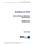
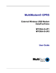
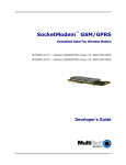
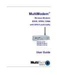
1
SocketModem™ CDMA
Embedded Data/Fax Wireless Modem
MTSMC-C
A Global CDMA 2000 1xRTT, 800/1900 MHz Wireless Modem
Developer’s Guide
SocketModem CDMA Developer’s Guide
MTSMC-C – A Global CDMA 2000 1xRTT, 800/1900 MHz Wireless Modem
PN S000298B, Version B
Copyright
This publication may not be reproduced, in whole or in part, without prior expressed written permission
from Multi-Tech Systems, Inc. All rights reserved.
Copyright © 2003-2004, by Multi-Tech Systems, Inc.
Multi-Tech Systems, Inc. makes no representations or a warranty with respect to the contents hereof and
specifically disclaims any implied warranties of merchantability or fitness for any particular purpose.
Furthermore, Multi-Tech Systems, Inc. reserves the right to revise this publication and to make changes
from time to time in the content hereof without obligation of Multi-Tech Systems, Inc. to notify any person
or organization of such revisions or changes.
Revisions
Revision Level
A
B
Date
06/09/03
03/30/04
Description
Initial release.
Update Features list. Change Operating Temperatures. Add Universal
Socket information.
Patents
This device covered by the following patent: 5,673,268
Trademarks
Multi-Tech Trademarks: SocketModem, Multi-Tech, and the Multi-Tech logo.
All other products and technologies are the trademarks or registered trademarks of their respective
holders.
World Headquarters
Multi-Tech Systems, Inc.
2205 Woodale Drive
Mounds View, Minnesota 55112
Phone: 763-785-3500 or 800-328-9717
Fax: 763-785-9874
Technical Support
Country
By Email
France:
[email protected]
India:
[email protected]
U.K.:
[email protected]
U.S. and Canada:
[email protected]
Rest of the World:
[email protected]
Internet Address: http://www.multitech.com
By Phone
(33) 1-64 61 09 81
91 (124) 6340778
(44) 118 959 7774
(800) 972-2439
(763) 717-5863
Table of Contents
Table of Contents
CHAPTER 1 – PRODUCT DESCRIPTION AND SPECIFICATIONS .......................................................... 4
PRODUCT DESCRIPTION ............................................................................................................................... 4
APPLICATIONS.............................................................................................................................................. 4
PRODUCT FEATURES .................................................................................................................................... 4
FEATURE DETAILS ........................................................................................................................................ 5
DEVELOPER’S KIT ........................................................................................................................................ 5
TECHNICAL SPECIFICATIONS ......................................................................................................................... 6
RELATED MANUALS ...................................................................................................................................... 6
ADDITIONAL RESOURCES .............................................................................................................................. 6
CHAPTER 2 – MECHANICAL SPECIFICATIONS ...................................................................................... 7
PHYSICAL DIMENSION................................................................................................................................... 7
PIN CONFIGURATIONS .................................................................................................................................. 8
Pin Descriptions...................................................................................................................................... 8
CHAPTER 3 – ELECTRICAL CHARACTERISTICS ................................................................................... 9
I/O ELECTRICAL CHARACTERISTICS .............................................................................................................. 9
POWER CONSUMPTION ................................................................................................................................. 9
HANDLING PRECAUTIONS ............................................................................................................................. 9
CHAPTER 4 – SOCKETMODEM INTERFACES....................................................................................... 10
FLASHING LED INTERFACE ......................................................................................................................... 10
RF INTERFACE ........................................................................................................................................... 10
RF Connector ....................................................................................................................................... 10
CHAPTER 5 – SOCKETMODEM TEST BOARD ...................................................................................... 11
SERIAL TEST/DEMO BOARD COMPONENTS .................................................................................................. 11
SERIAL TEST/DEMO BOARD BLOCK DIAGRAM .............................................................................................. 12
CHAPTER 6 – APPLICATION CONSIDERATIONS ................................................................................. 13
GENERAL GUIDELINES FOR THE USE OF THE SOCKETMODEM ....................................................................... 13
Hardware and RF ................................................................................................................................. 13
The Antenna ......................................................................................................................................... 13
Soldering and Cleaning the SocketModem .......................................................................................... 13
FIRMWARE UPGRADE ................................................................................................................................. 13
INITIAL CONFIGURATION USING MOBILE PHONETOOLS ................................................................................. 13
APPENDIX A – SAFETY ............................................................................................................................ 14
SAFETY PRECAUTIONS ............................................................................................................................... 14
RF Safety.............................................................................................................................................. 14
General Safety...................................................................................................................................... 15
General Safety Standards .................................................................................................................... 16
RF Exposures ....................................................................................................................................... 16
Instructions to OEMs ............................................................................................................................ 16
APPENDIX B – SOURCES FOR PERIPHERAL DEVICES ...................................................................... 17
CDMA ANTENNA ....................................................................................................................................... 17
MMCX PLUG ............................................................................................................................................. 17
ANTENNA CABLE ........................................................................................................................................ 17
APPENDIX C – AT COMMANDS............................................................................................................... 18
APPENDIX D – ACRONYMS AND ABBREVIATIONS ............................................................................. 19
APPENDIX E – WARRANTY AND REPAIRS ........................................................................................... 20
Multi-Tech Warranty Statement............................................................................................................ 20
Repair Procedures for U.S. and Canadian Customers ........................................................................ 20
Repair Procedures for International Customers (Outside U.S.A. and Canada)................................... 21
Repair Procedures for International Distributors .................................................................................. 21
INDEX ......................................................................................................................................................... 22
Multi-Tech Systems, Inc. SocketModem CDMA Developer’s Guide
3
Chapter 1 – Product Description and Specifications
Chapter 1 – Product Description and
Specifications
Product Description
The Multi-Tech SocketModem CDMA is a complete, ready-to-integrate, embedded wireless modem.
Designed for global use, it offers standards-based multi-band CDMA200 1x performance. The
SocketModem CDMA is based on industry-standard open interfaces and utilizes Multi-Tech’s universal
socket design.
Applications
The CDMA SocketModem is targeted at applications that periodically need to send or receive data over a
wireless network. It is an ideal solution for:
•
•
•
•
•
•
•
•
•
•
•
Appliances
ATM terminals
Automotive
Data collection
Gas pumps
Industrial and medical remote monitoring systems
Remote diagnostics
Remote metering
Security systems
Vending/gaming machines
Other devices requiring wireless connectivity
Product Features
•
•
•
•
•
•
•
•
•
•
•
•
•
•
•
•
•
CDMA200 1xRTT
CDMA IS-95-A, IS-95B
Class 2.0 Group 3 FAX
Dual-band 800/1900 CDMA
Short Message Services features including text SMS mobile originated, SMS mobile
terminated, cell broadcast, Over the Air Activation (OTA), OTASP, OTAPA
14.4K circuit switched data
MMCX antenna connector
Serial interface supports DTE speeds to 230K
AT command compatible*
Phone book management
Personal Information Management (PIM)
Fixed dialing number
Real time clock
Alarm management
Packet data up to 153K bps forward and reverse
Circuit-switched data up to 14.4K bps
Universal socket connectivity
*AT Commands - AT commands for this product are published in a separate document available on the
Developer’s Kit product CD or from Multi-Tech. For a copy of this document, contact OEM Sales at
[email protected] or call (800) 972-2439.
Multi-Tech Systems, Inc. SocketModem CDMA Developer’s Guide
4
Chapter 1 – Product Description and Specifications
Feature Details
Integration Reduces Space, Power, and Cost. The SocketModem CDMA integrates the controller,
RF transceiver, and antenna interface in one module. This integration requires low power and low
real estate, and it provides an overall reduction in costs.
Reduces Development Time. The SocketModem CDMA can make your existing and next
generation device, machine, or system communication-ready without requiring significant hardware
changes to its design. This complete, ready-to-integrate wireless SocketModem allows you to
enhance your product while you focus on developing its core features.
Short Message Services. The SocketModem CDMA offers SMS features such as mobile originated,
mobile terminated, cell broadcast, Over the Air Activation (OTA), OTASP, and OTAPA.
Management Features. The SocketModem CDMA provides advanced management features that
include: phone book management, fixed dialing number, real time clock, and alarm management.
Industry-standard Modem Commands. The SocketModem CDMA provides industry-standard ATstyle commands for ease of integration into your existing software application.
SocketModem Pin-Out. The SocketModem CDMA interfaces easily with existing products through a
standard serial communication channel. The complete on-board RF transceiver interfaces with an
antenna for direct connection to wireless SMS, circuit-switched dial-up, or packet data networks. The
SocketModem also includes an onboard LED to display network status. The SocketModem is a Data
Terminal Equipment (DTE) device with serial asynchronous protocol support. The serial DTE channel
is capable of transfer speeds to 230K bps and can be interfaced directly to a UART or microcontroller.
Packet-switched Data. The SocketModem CDMA supports CDMA 2000 1xRTT packet-switched
cellular data. This enables mobile Internet functionality by allowing interworking between the existing
Internet and the cellular network at speeds up to 153K bps (forward and reverse). Any service that is
used over the fixed Internet today - File Transfer Protocol (FTP), web browsing, chat, e-mail, telnet is
available over the cellular network as well.
Circuit-switched Data (CSD). The SocketModem CDMA also supports CDMA IS-95A and IS-95B
circuit-switched cellular data connections. Circuit-switched data connections support speeds up to
14.4K bps as well as Class 2.0 Group 3 fax. CSD cellular wireless connections are ideal for
applications that require a quick wireless replacement of an existing point-to-point analog dial-up
connection. They integrate seamlessly with your current application requiring little infrastructure
change.
Universal Socket Connectivity. The SocketModem's flexible comm-port architecture provides dialup, wireless, or Ethernet socket connectivity with interchangeable modules. This means you can
utilize one system design and populate it with your communication module of choice. In addition, you
are assured a seamless migration to future technologies.
Developer’s Kit
The SocketModem CDMA Developer’s Kit allows you to plug in the SocketModem and use it for
testing, programming, and evaluation. The kit includes:
• one development board with RS-232 DB-25 connector
• universal power supply
• antenna
• RS-232 cable
Multi-Tech Systems, Inc. SocketModem CDMA Developer’s Guide
5
Chapter 1 – Product Description and Specifications
Technical Specifications
The SocketModem CDMA meets the following specifications:
Fax Compatibility
Weight
Dimensions
Power Requirements
Operating Environment
Storage Temperature
Certifications
Cleaning
CDMA Class 2.0 Group 3 Fax
1.2 oz (34 g)
3.1” w x 1.4” h x 0.5” d
(8.0 cm x 3.5 cm x 1.2 cm)
5 VDC; 400mA Typical, 700mA Maximum
-30° to +70° C
-30° to +85° C
EMC: FCC Part 2, 15, 22, 24, EN 55022 & EN55024
Safety: UL 60950, EN 60950
No cleaning/washing due to the manufacturing process used to
produce this product
Related Manuals
AT commands for this product are published in a separate document available on the Developer’s Kit
system CD or from Multi-Tech. Multi-Tech manuals and other resources are available on the MultiTech Web page at http://www.multitech.com.
Additional Resources
European Telecommunications Standards Institute (ETSI) - Contact the ETSI at:
650, route des Lucioles
06921 Sophia-Antipolis Cedex
France
Tel: +33 (0)4 92 94 42 00
Fax: +33 (0)4 93 65 47 16
http://www.etsi.org
Global Engineering Documents manages a collection of more than one million documents from over
460 organizations worldwide:
http://global.ihs.com
Phone: 800-854-7179
Fax: 303-792-2192
The ITU is the leading publisher of telecommunication technology, regulatory and standards
information, with over 4,000 titles in printed form, on CD-ROM and Online at
http://www.itu.int/publications/
Multi-Tech Systems, Inc. SocketModem CDMA Developer’s Guide
6
Chapter 2 – Mechanical Specifications
Chapter 2 – Mechanical
Specifications
Physical Dimension
SocketModem CDMA Mechanical Drawing
Multi-Tech Systems, Inc. SocketModem CDMA Developer’s Guide
7
Chapter 2 – Mechanical Specifications
Pin Configurations
The SocketModem CDMA uses a 13-pin interface.
SocketModem Pins - Top View
Pin Descriptions
Pin #
24
26, 41, 63
33
34
35
36
37
38
39
40
61
Signal
I/O
Description
Name
Type
-RESET I/O
Reset. This signal is used to force a reset procedure by providing low level during
at least 500µs. This signal is considered an emergency reset only. A reset
procedure is already driven by an internal hardware during the power-up
sequence.
This signal can also be used to provide a reset to an external device. It then acts
as an output. If no external reset is necessary, this input can be left open. If used
(emergency reset), it has to be driven by an open collector or an open drain.
GND
Ground
–RTS
I
Request to Send. The –RTS signal is used for hardware flow control.
–RXD
O
Received Data. The modem uses the RXD line to send received data to the DTE
and to send modem responses to the DTE.
–TXD
I
Transmitted Data. The DTE uses the –TXD line to send data to the modem or to
transmit commands to the modem.
–RI
O
Ring Indicate. –RI output ON (low) indicates the presence of a ring signal ON
segment.
–DSR
O
Data Set Ready. –DSR indicates modem status to the DTE. –DSR OFF (high)
indicates that the DTE is to disregard all signals appearing on the interchange
circuits except Ring Indicator (–RI). It reflects the status of the local data set and
does not indicate an actual link with any remote data equipment.
–CTS
O
Clear To Send. –CTS is controlled by the modem to indicate whether or not the
modem is ready to transmit data. –CTS ON, indicates to the DTE that signals
presented on TXD will be transmitted. –CTS OFF indicates to the DTE that it
should not transfer data across the interface on TXD.
–DCD
O
Data Carrier Detect. –DCD output is ON (low) when a data connection is
established.
–DTR
I
Data Terminal Ready (Active Low). The –DTR input is turned ON (low) by the
DTE when the DTE is ready to transmit or receive data. –DTR ON prepares the
modem to be connected, and, once connected, maintains the connection.
–DTR OFF places the modem in the disconnect state.
VCC
PWR +5V
Multi-Tech Systems, Inc. SocketModem CDMA Developer’s Guide
8
Chapter 3 – Electrical Characteristics
Chapter 3 – Electrical Characteristics
Electrical characteristics for the 5V Serial SocketModem are presented in this chapter.
I/O Electrical Characteristics
5 Vdc Characteristics (TA = -20° C to 55° C; VDD = 5 V ± 0.25 V) VDDMAX = 5.25 V
Digital Inputs
Input High Input Low
–DTR (40), –TXD (35), –RTS (33), –RESET (24)
Min 3.675 V Max 1.4 V
Digital Outputs
Output High Output Low Current
–DCD (39), –CTS (38), –DSR (37), –RI (36), –RXD (34)
Min. 4 V
Max 0.4 V
Drive: 2 ma
Digital Input Capacitance
5 PF
Power Consumption
Operating Mode
CDMA RXTX
Full Power
CMA RXTX
Average Power
CDMA Standby
Band
Cellular
PCS
Cellular
PCS
Cellular
Average (mA)
615
770
340
445
20
PCS
20
Handling Precautions
All devices must be handled with certain precautions to avoid damage due to the accumulation of static
charge. Although input protection circuitry has been incorporated into the devices to minimize the effect of
this static buildup, proper precautions should be taken to avoid exposure to electrostatic discharge during
handling and mounting.
Multi-Tech Systems, Inc. SocketModem CDMA Developer’s Guide
9
Chapter 4 – SocketModem Interfaces
Chapter 4 – SocketModem Interfaces
This chapter describes the SocketModem interfaces.
• Flashing LED Interface
• RF Interface
Flashing LED Interface
The flashing LED signal is used to indicate the working mode of the SocketModem.
LED and SocketModem Status
Signal
OFF
ON
SocketModem Status
Download mode or switched OFF>
Continuously lit
Switched ON (not registered on the network)
Flashing
Switched ON (registered on the network)
RF Interface
The impedance is 50 Ohms nominal.
RF Connector
The RF connector is MMCX standard type. An antenna can be directly connected through the mating
connector or using a small adapter.
Multi-Tech Systems, Inc. SocketModem CDMA Developer’s Guide
10
Chapter 5 – SocketModem Test Board
Chapter 5 – SocketModem Test Board
Serial Test/Demo Board Components
Multi-Tech Systems, Inc. SocketModem CDMA Developer’s Guide
11
Chapter 5 – SocketModem Test Board
Serial Test/Demo Board Block Diagram
Block Diagram for the SocketModem CDMA
Multi-Tech Systems, Inc. SocketModem CDMA Developer’s Guide
12
Chapter 6 – Application Considerations
Chapter 6 – Application
Considerations
General Guidelines for the Use of the SocketModem
Hardware and RF
• Ground plane: Multi-Tech recommends having a common ground plane for analog, digital, and
RF grounds.
• ESD protection on serial link, …
• Possible spurious emission radiated by the application to the RF receiver in the receiver band.
The Antenna
The antenna sub-system and integration in the application is a major issue. It is a major issue in the
choice of the antenna cable (type, length, performances, thermal resistance, etc.)
These elements could affect CDMA performances such as sensitivity and emitted power.
The antenna should be isolated as much as possible from the digital circuitry including the interface
signals.
Multi-Tech recommends shielding the terminal. On terminals including the antenna, a poor shielding
could dramatically affect the sensitivity of the terminal. Subsequently, the power emitted through the
antenna could affect the application.
Soldering and Cleaning the SocketModem
The pins of the SocketModem may be hand soldered or wave soldered. If wave soldered, the
temperature on the top of the SocketModem must not exceed 100° C.
There should be no solvent or water washing of the SocketModem.
Do not use a hot air gun on the SocketModem.
Firmware Upgrade
The SocketModem firmware is stored in flash memory, and it can easily be upgraded. Contact the factory
for details.
Initial Configuration Using Mobile PhoneTools
For initial configuration of your wireless device, Multi-Tech offers a Windows-based mobile PhoneTools
application.
To load Mobile PhoneTools, click the Mobile PhoneTools icon on the product CD and follow the onscreen prompts.
Multi-Tech Systems, Inc. SocketModem CDMA Developer’s Guide
13
Appendix A – Safety
Appendix A – Safety
Safety Precautions
IMPORTANT!
FOR THE EFFICIENT AND SAFE OPERATION
OF YOUR CDMA INTEGRATED MODEM
READ THIS INFORMATION BEFORE USE.
RF Safety
General
Your SocketModem is based on the CDMA standard for cellular technology. Your modem is actually
a low power radio transmitter and receiver. It sends out and receives radio frequency energy. When
you use your SocketModem integrated modem, the cellular system, which handles your calls controls
both the radio frequency and the power level of your cellular modem.
Exposure to RF Energy
There has been some public concern about possible health effects of using CDMA modems.
Although research on health effects from RF energy has focused on the current RF technology for
many years, scientists have begun research regarding newer radio technologies, such as CDMA.
After existing research had been reviewed, and after compliance to all applicable safety standards
had been tested, it has been concluded that the product was fitted for use. If you are concerned about
exposure to RF energy there are things you can do to minimize exposure. Obviously, limiting the
duration of your calls will reduce your exposure to RF energy. In addition, you can reduce RF
exposure by operating your cellular modem efficiently by following the below guidelines.
Efficient Modem Operation
For your modem to operate at the lowest power level, consistent with satisfactory call quality:
• If your modem has an extendible antenna, extend it fully. Some models allow you to place a
call with the antenna retracted. However your modem operates more efficiently with the
antenna fully extended.
• Do not hold the antenna when the modem is IN USE. Holding the antenna affects call quality
and may cause the modem to operate at a higher power level than needed.
Antenna Care and Replacement
Do not use the modem with a damaged antenna. If a damaged antenna comes into contact with the
skin, a minor burn may result. Replace a damaged antenna immediately. Consult your manual to see
if you may change the antenna yourself. If so, use only a manufacturer-approved antenna. Otherwise,
have your antenna repaired by a qualified technician. Use only the supplied or approved antenna.
Unauthorized antennas, modifications, or attachments could damage the modem and may
contravene local RF emission regulations or invalidate type approval.
Multi-Tech Systems, Inc. SocketModem CDMA Developer’s Guide
14
Appendix A – Safety
General Safety
Driving
Check the laws and the regulations regarding the use of cellular devices in the area where you have
to drive as you must comply with these laws and regulations. When using your modem while driving,
please give full attention to driving. Pull off the road and park before making or answering a call if
driving conditions so require.
Electronic Devices
Most electronic equipment, for example in hospitals and motor vehicles, is shielded from RF energy.
However, RF energy may affect some improperly shielded electronic equipment.
Vehicle Electronic Equipment
Check your vehicle manufacturer representative to determine if any on-board electronic equipment is
adequately shielded from RF energy.
Medical Electronic Equipment
Consult the manufacturer of any personal medical devices (such as pacemakers, hearing aids, etc.)
to determine if they are adequately shielded from external RF energy. Turn your modem OFF in
health care facilities when any regulations posted in the area instruct you to do so. Hospitals or health
care facilities may be using RF monitoring equipment.
Aircraft
Turn your modem OFF before boarding any aircraft.
• Use it on the ground only with crew permission.
• Do not use it in the air.
To prevent possible interference with aircraft systems, Federal Aviation Administration (FAA)
regulations require you to have permission from a crew member to use your modem while the aircraft
is on the ground. To prevent interference with cellular systems, local RF regulations prohibit using
your modem while airborne.
Children
Do not allow children to play with your modem. It is not a toy. Children could hurt themselves or
others (by poking themselves or others in the eye with the antenna, for example). Children could
damage the modem or make calls that increase your modem bills.
Blasting Areas
To avoid interfering with blasting operations, turn your unit OFF when in a “blasting area” or in areas
posted “turn off two-way radio”. Construction crews often use remote control RF devices to set off
explosives.
Potentially Explosive Atmospheres
Turn your modem OFF when in any area with a potentially explosive atmosphere. It is rare, but your
modem or its accessories could generate sparks. Sparks in such areas could cause an explosion or
fire resulting in bodily injuries or even death. Areas with a potentially explosive atmosphere are often,
but not always, clearly marked. They include fueling areas such as gas stations; below deck on boats;
fuel or chemical transfer or storage facilities; and areas where the air contains chemicals or particles,
such as grain, dust, or metal powders. Do not transport or store flammable gas, liquid, or explosives,
in the compartment of your vehicle, which contains your modem or accessories. Before using your
modem in a vehicle powered by liquefied petroleum gas (such as propane or butane) ensure that the
vehicle complies with the relevant fire and safety regulations of the country in which the vehicle is to
be used.
Multi-Tech Systems, Inc. SocketModem CDMA Developer’s Guide
15
Appendix A – Safety
General Safety Standards
THIS WIRELESS SOCKETMODEM COMPLIES WITH ALL APPLICABLE RF SAFETY STANDARDS.
This cellular modem meets the standards and recommendations for the protection of public exposure to
RF electromagnetic energy that have been established by governmental bodies and other qualified
organizations, such as the following:
•
Directives of the European Community,
•
Directorate General V in Matters of Radio Frequency Electromagnetic Energy
RF Exposures
Pursuant to 47 CFR § 24.52 of the FCC Rules and Regulations, personal communications services
(PCS) equipment is subject to the radio frequency radiation exposure requirements specified in §
1.1307(b), § 2.1091 and § 2.1093 as appropriate.
The Multi-Tech SocketModem is a CDMA (PCS 800/1900) terminal which operates in the US
licensed PCS frequency spectrum. The device transmits over the 1850-1910 MHz or 824-849 MHz
bands and receives over the 1930-1990 MHz or 869-894 MHz bands. Multi-Tech Systems, Inc.
certifies that it has determined that the Modem complies with the RF hazard requirements applicable
to broadband PCS equipment operating under the authority of 47 CFR Part 24, Subpart E of the FCC
Rules and Regulations. This determination is dependent upon installation, operation, and use of the
equipment in accordance with all instructions provided.
The modem is designed for and intended to be used in fixed and mobile applications. "Fixed" means
that the device is physically secured at one location and is not able to be easily moved to another
location. "Mobile" means that the device is designed to be used in other than fixed locations and
generally in such a way that a separation distance of at least 20 cm is normally maintained between
the transmitter's antenna and the body of the user or nearby persons. The Modem is not designed for
or intended to be used in portable applications (within 20 cm of the body of the user) and such uses
are strictly prohibited. To ensure that the unit complies with current FCC regulations limiting both
maximum RF output power and human exposure to radio frequency radiation, a separation distance
of at least 20 cm must be maintained between the unit's antenna and the body of the user and any
nearby persons at all times and in all applications and uses. Additionally, in mobile applications,
maximum antenna gain must not exceed 3 dBi to comply with Section 24.232(b) and is limited to 7
dBi for fixed applications. Finally, the tune-up procedure for the modem ensures that the maximum
RF output power of the device does not exceed 30.0 dBm within the variations that can be expected
due to quantity production and testing on a statistical basis.
Instructions to OEMs
The Multi-Tech product manual includes specific warnings and cautions in order to ensure that OEMs
are aware of their responsibilities, with regards to RF exposure compliance, for products into which
the modem is integrated. With this guidance, the OEM will be able to incorporate into their
documentation the necessary operating conditions and warnings.
OEMs need to provide a manual with the ‘’final’’ product that clearly states the operating requirements
and conditions and that these must be observed to ensure compliance with current FCC RF exposure
requirements / MPE limits (see the “RF Exposures” section above). This will enable the OEM to
generate (and provide the end-user with) the appropriate operating instructions, warnings and
cautions, and/or markings for their product.
Multi-Tech Systems, Inc. SocketModem CDMA Developer’s Guide
16
Appendix B – Sources for Peripheral Devices
Appendix B – Sources for Peripheral
Devices
CDMA Antenna
The integrated modem antenna connector is a MMCX connector. The MMCX connector incorporates a
'Snap On' latching action in order to make the connection easier with an excellent RF performance. An
additional advantage is its small physical size, which is 50% of the standard MCX connector.
This type of connector is suitable for the standard ranges of flexible and semi-rigid cables. The
characteristic impedance of the MMCX coaxial connector is 50 ohm. The antenna manufacturer must
guarantee that the antenna will be working according to the radio characteristics presented in the table
below.
Radio Characteristics
Frequency RX
Frequency TX
Impedance
VSWR
Typical Radiated Gain
CDMA 800
869 to 894 MHz
824 to 849 MHz
CDMA 1900
1930 to 1990 MHz
1850 to 1910 MHz
50 ohms
<1.5
0 dBi in at least one direction
Antenna
An antenna with matting connector can be ordered, for example, from:
IMS Connectors Systems GMBH
http://www.imscs.com/
MMCX Plug
The SocketModem requires an MMCX plug to connect to an antenna.
MMCX Connector Example (right angle type)
MMCX / SMA Adapter
A small MMCX / SMA adapter can be ordered, for example, from:
Amphenol
http://www.amphenol.com
Order No: 908-31100
Antenna Cable
An optional 6” antenna cable can be ordered from Multi-Tech Systems, Inc.
6-Inch Antenna Cable – SMA Jack to MMCX Plug
Antenna Cable – SMA Jack to MMCX Plug
Multi-Tech Systems, Inc.
http://www.multitech.com/
Order No: 45009630
Multi-Tech Systems, Inc. SocketModem CDMA Developer’s Guide
17
Appendix C – AT Commands
Appendix C – AT Commands
AT Commands for the CDMA wireless modem are published in a separate Reference Guide included on
the product CD and the Multi-Tech Web site.
Multi-Tech Systems, Inc. SocketModem CDMA Developer’s Guide
18
Appendix D – Acronyms and Abbreviations
Appendix D – Acronyms and
Abbreviations
ADC – Analog Digital Converter
ASIC – Application Specific Integrated Circuit
BCCH – Broadcast Control Channel
CLK – Clock
CTS – Clear To send
dB – decibel
DCD – Data Carrier Detect
DCE – Data Circuit Terminating Equipment
DSR – Data Set Ready
DTE – Data Terminal Equipment
DTR – Data Terminated Ready
EFR – Enhanced Full Rate
ECDMA – Extended CDMA
EMC – Electromagnetic Conformity
EN – Enable
ETSI – European Telecommunications Standards Institute
FAC – Final Assembly Code
FR – Full-Rate
FTA – Full Type Approval
GND – Ground
GPIO – General Purpose Input Output
CDMA – Global System for Mobile Communication
HR – Half-Rate
IMEI – International Mobile Equipment Identity
MO – Mobile Originated
MT – Mobile Terminated
OEM – Original Equipment Manufacturer
PDA – Personal Digital Assistant
PCB – Printed Circuit Board
PRES – Presence
RF – Radio Frequency
RI – Ring Indicator
RTS – Request To Send
SMD – Surface Mounted Design
SMS – Short Message Service
TAC – Type Approval Code
TDMA – Time Code Multiple Access
TE – Terminal Equipment
VSWR – Voltage Standing Wave Ratio
WAP – Wireless Application Protocol
Multi-Tech Systems, Inc. SocketModem CDMA Developer’s Guide
19
Appendix E – Warranty and Repairs
Appendix E – Warranty and Repairs
Multi-Tech Warranty Statement
Multi-Tech Systems, Inc., (hereafter “MTS”) warrants that its products will be free from defects in material or
workmanship for a period of two, five, or ten years (depending on model) from date of purchase, or if proof of
purchase is not provided, two, five, or ten years (depending on model) from date of shipment.
MTS MAKES NO OTHER WARRANTY, EXPRESS OR IMPLIED, AND ALL IMPLIED WARRANTIES OF
MERCHANTABILITY AND FITNESS FOR A PARTICULAR PURPOSE ARE HEREBY DISCLAIMED.
This warranty does not apply to any products which have been damaged by lightning storms, water, or power surges
or which have been neglected, altered, abused, used for a purpose other than the one for which they were
manufactured, repaired by Customer or any party without MTS’s written authorization, or used in any manner
inconsistent with MTS’s instructions.
MTS’s entire obligation under this warranty shall be limited (at MTS’s option) to repair or replacement of any products
which prove to be defective within the warranty period or, at MTS’s option, issuance of a refund of the purchase price.
Defective products must be returned by Customer to MTS’s factory — transportation prepaid.
MTS WILL NOT BE LIABLE FOR CONSEQUENTIAL DAMAGES, AND UNDER NO CIRCUMSTANCES WILL ITS
LIABILITY EXCEED THE PRICE FOR DEFECTIVE PRODUCTS.
Repair Procedures for U.S. and Canadian Customers
In the event that service is required, products may be shipped, freight prepaid, to our Mounds View, Minnesota
factory:
Multi-Tech Systems, Inc.
2205 Woodale Drive
Mounds View, MN 55112
Attn: Repairs, Serial # ____________
A Returned Materials Authorization (RMA) is not required. Return shipping charges (surface) will be paid by MTS to
destinations in U.S. and Canada.
Please include, inside the shipping box, a description of the problem, a return shipping address (must have street
address, not P.O. Box), your telephone number, and if the product is out of warranty, a check or purchase order for
repair charges.
For out of warranty repair charges, go to www.multitech.com/DOCUMENTS/Company/warranty/
Extended two-year overnight replacement service agreements are available for selected products. Please call MTS
customer service at (888) 288-5470 or visit our web site at www.multitech.com/PARTNERS/Programs/orc/ for details
on rates and coverage’s.
Please direct your questions regarding technical matters, product configuration, verification that the product is
defective, etc., to our Technical Support department at (800) 972-2439 or email [email protected]. Please
direct your questions regarding repair expediting, receiving, shipping, billing, etc., to our Repair Accounting
department at (800) 328-9717 or (763) 717-5631, or email [email protected].
Repairs for damages caused by lightning storms, water, power surges, incorrect installation, physical abuse, or usercaused damages are billed on a time-plus-materials basis.
Multi-Tech Systems, Inc. SocketModem CDMA Developer’s Guide
20
Appendix E – Warranty and Repairs
Repair Procedures for International Customers (Outside U.S.A. and Canada)
Your original point of purchase Reseller may offer the quickest and most economical repair option for your Multi-Tech
product. You may also contact any Multi-Tech sales office for information about the nearest distributor or other repair
service for your Multi-Tech product. The Multi-Tech sales office directory is available at
www.multitech.com/PARTNERS/Channels/offices/
In the event that factory service is required, products may be shipped, freight prepaid to our Mounds View, Minnesota
factory. Recommended international shipment methods are via Federal Express, UPS or DHL courier services, or by
airmail parcel post; shipments made by any other method will be refused. A Returned Materials Authorization (RMA)
is required for products shipped from outside the U.S.A. and Canada. Please contact us for return authorization and
shipping instructions on any International shipments to the U.S.A. Please include, inside the shipping box, a
description of the problem, a return shipping address (must have street address, not P.O. Box), your telephone
number, and if the product is out of warranty, a check drawn on a U.S. bank or your company’s purchase order for
repair charges. Repaired units shall be shipped freight collect, unless other arrangements are made in advance.
Please direct your questions regarding technical matters, product configuration, verification that the product is
defective, etc., to our Technical Support department nearest you or email [email protected]. When calling the
U.S., please direct your questions regarding repair expediting, receiving, shipping, billing, etc., to our Repair
Accounting department at +(763) 717-5631 in the U.S.A., or email [email protected].
Repairs for damages caused by lightning storms, water, power surges, incorrect installation, physical abuse, or usercaused damages are billed on a time-plus-materials basis.
Repair Procedures for International Distributors
International distributors should contact their MTS International sales representative for information about the repairs
for their Multi-Tech product.
Please direct your questions regarding technical matters, product configuration, verification that the product is
defective, etc., to our International Technical Support department at +(763)717-5863. When calling the U.S., please
direct your questions regarding repair expediting, receiving, shipping, billing, etc., to our Repair Accounting
department at +(763) 717-5631 in the U.S.A. or email [email protected].
Repairs for damages caused by lightning storms, water, power surges, incorrect installation, physical abuse, or usercaused damages are billed on a time-plus-materials basis.
Multi-Tech Systems, Inc. SocketModem CDMA Developer’s Guide
21
Index
Index
ADC..................................................................19
aircraft and safety.............................................15
antenna ......................................................10, 13
antenna cable.............................................13, 17
antenna care and replacement ........................14
applications ........................................................4
ASIC .................................................................19
AT commands documentation .......................4, 6
BCCH ...............................................................19
blasting areas and safety .................................15
Block Diagram..................................................12
CDMA...............................................................19
CDMA antenna.................................................17
children and safety ...........................................15
Cleaning Safety Standards ..............................13
CTS ..................................................................19
dB .....................................................................19
DCD..................................................................19
DCE..................................................................19
Developer’s Kit ...................................................5
driving safety ....................................................15
DSR..................................................................19
DTE ..................................................................19
DTR ..................................................................19
EFR ..................................................................19
Electrical characteristics.....................................9
electronic devices and safety ...........................15
EMC .................................................................19
EN ....................................................................19
ESD protection .................................................13
ETSI .................................................................19
explosive atmospheres and safety...................15
Exposure to RF Energy....................................14
FAC ..................................................................19
features ..............................................................4
flashing LED interface ......................................10
FR.....................................................................19
FTA...................................................................19
gain...................................................................16
GND .................................................................19
GPIO ................................................................19
Handling Precautions .........................................9
Hardware and RF.............................................13
HR ....................................................................19
IMEI.................................................................. 19
initial configuration ........................................... 13
Instructions to OEMs ....................................... 16
interfaces ......................................................... 10
Mechanical Drawing........................................... 7
medical electronic equipment and safety ........ 15
MMCX (Miniature Micro Connector) .......... 10, 17
MO ................................................................... 19
MT .................................................................... 19
OEM................................................................. 19
operating conditions......................................... 16
PCB.................................................................. 19
PCS.................................................................. 16
PDA.................................................................. 19
PhoneTools...................................................... 13
Pin Descriptions ................................................. 8
Power Consumption........................................... 9
PRES ............................................................... 19
radio ................................................................. 14
Repairs............................................................. 20
RF .................................................................... 19
RF connector ................................................... 10
RF Exposures .................................................. 16
RF Interface ..................................................... 10
RF safety.......................................................... 14
RI ..................................................................... 19
RTS.................................................................. 19
safety ............................................................... 14
Safety Standards ............................................. 16
SMD ................................................................. 19
SMS ................................................................. 19
Soldering Safety Standards ............................. 13
Specifications
technical ......................................................... 6
TAC.................................................................. 19
TDMA............................................................... 19
TE .................................................................... 19
Technical specifications ..................................... 6
vehicle electronic equipment and safety.......... 15
VSWR .............................................................. 19
WAP................................................................. 19
Warranty .......................................................... 20
Multi-Tech Systems, Inc. SocketModem CDMA Developer’s Guide
22