1
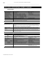
PS Series
PS8 - Analogue TDcontroller PS8 - PS8Amp - LS400
PS10 - Analogue TDcontroller PS10- PS10Amp - LS500
PS15 - PS15Bass - Analogue TDcontroller PS15 - LS1200
User Manual
Manuel d’Utilisation (p. 41)
P.2
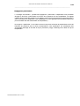
ANALOGUE TDCONTROLLER DECLARATION OF CONFORMITY
___________________________________________________________________________________________________
Analogue TDcontroller Declaration of conformity
This equipment has been tested and found to comply with the safety objectives and essential requirements of European (73/23/EEC and
89/336/EEC directives) and international Standards, by fulfilling the requirements of the following harmonized standards:
Electrical Safety (EU) : IEC 60065 (12/2001) Audio, video and similar electronic apparatus
Electrical Safety (US) : UL60065 Seventh Edition, dated June 30, 2003 category AZSQ, E241312.
Electrical Safety (CAN) : CSA-C22.2 N°60065:03 Edition, dated April 2003 category AZSQ7, E241312
Electrical Safety (Rest of the World) : CB test certificate DK-8371 based on IEC60065-2001 7nd ed. with all national deviations.
Radiated Emission (EU) : EN55103-1 (1996) Electromagnetic compatibility - Product family standard for audio, video, audiovisual and entertainment lighting control apparatus for professional use.
Audio Equipment
Radiated Emission (US) : FFC part15 class B
10CE
Radiated Emission (CAN) : This Class B digital apparatus complies with Canadian ICES-003.
RF Immunity (EU) : EN55103-2 (1996) Electromagnetic compatibility - Product family standard for audio, video, audio-visual and
entertainment lighting control apparatus for professional use.
Note: EMC conformance testing is based on the use of recommended cable types. The use of other cable types may degrade EMC
performances.
IMPORTANT SAFETY INSTRUCTIONS
1) Read these instructions.
2) Keep these instructions.
3) Heed all warnings.
4) Follow all instructions.
5) Do not use this apparatus near water.
6) Clean only with dry cloth.
7) Do not block any ventilation openings. Install in accordance with the
manufacturer’s instructions.
8) Do not install near any heat sources such as radiators, heat registers,
stoves, or other apparatus (including amplifiers) that produce heat.
9) Do not defeat the safety purpose of the polarized or grounding-type plug. A
polarized plug has two blades with one wider than the other. A grounding type
plug has two blades and a third grounding prong. The wide blade or the third
prong are provided for your safety. If the provided plug does not fit into your
outlet, consult an electrician for replacement of the obsolete outlet. (US
market)
10) Protect the power cord from being walked on or pinched particularly at
plugs, convenience receptacles, and the point where they exit from the
apparatus.
11) Only use attachments/accessories specified by the manufacturer.
13) Unplug this apparatus during lightning storms or when unused for long
periods of time.
14) Refer all servicing to qualified service personnel. Servicing is required
when the apparatus has been damaged in any way, such as power-supply
cord or plug is damaged, liquid has been spilled or objects have fallen into the
apparatus, the apparatus has been exposed to rain or moisture, does not
operate normally, or has been dropped.
Information about products that generate electrical noise :
NOTE: The United States Federal Communications Commission (in 47 CFR
15.105) has specified that the following notice be brought to the attention of
users of this product:
This equipment has been tested and found to comply with the limits for a
Class B digital device, pursuant to Part 15 of the FCC Rules. These limits are
designed to provide reasonable protection against harmful interference in a
residential installation. This equipment generates, uses and can radiate radio
frequency energy and, if not installed and used in accordance with the
instructions, may cause harmful interference to radio communications.
However, there is no guarantee that interference will not occur in a particular
installation. If this equipment does cause harmful interference to radio or
television reception, which can be determined by turning the equipment off
and on, the user is encouraged to try to correct the interference by one or
more of the following measures:
- Reorient or relocate the receiving antenna.
- Increase the separation between the equipment and receiver.
- Connect the equipment into an outlet on a circuit different from that to which
the receiver is connected.
- Consult the dealer or an experienced radio/TV technician for help.
The user may find the following booklet, prepared by the Federal
Communications Commission, helpful: How to identify and Resolve Radio/TV
Interference Problems. This booklet is available from the U.S. Government
Printing Office, Washington, D.C. 20402, Stock No. 004-000-00345-4. Use of
a shielded cable is required to comply within Class B limits of Part 15 of FCC
Rules. Pursuant to Part 15.21 of the FCC Rules, any changes or
modifications to this equipment not expressly approved by NEXO S.A. may
cause, harmful interference and void the FCC authorization to operate this
equipment.
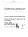
CAUTION
RISK OF ELECTRIC SHOCK
DO NOT OPEN
The lightning flash with arrowhead
symbol, within an equilateral triangle
is intended to alert the user to the
presence of uninsulated “dangerous
voltage” within the product's
enclosure that may be of sufficient
magnitude to constitute a risk of
electric shock to persons.
WARNING: To reduce the risk of fire or electric shock,
do not expose this apparatus to rain or moisture.
To avoid electrical shock, do not remove covers.
Dangerous voltages exist inside.
Refer all servicing to qualified personnel only.
The exclamation point within an
equilateral triangle is intended to
alert the user to the presence of
important operating and
maintenance (servicing) instructions
in the literature accompanying
the appliance.
WARNING ! This appliance is a CLASS 1 apparatus and must be earthed.
The green and yellow wire of the mains cord must always be connected to an installation safety earth or ground. The earth is essential for
personal safety as well as the correct operation of the system, and is internally connected to all exposed metal surfaces. Additional
recommendation for interconnection to other equipment can be found in the “Analogue TDcontroller Setting-Up Advice” section page 15.
PS SERIES MANUAL REV3 10/10/05
IMPORTANT SAFETY INSTRUCTIONS
P.3
___________________________________________________________________________________________________
ANALOGUE TDCONTROLLER DECLARATION OF CONFORMITY .........................................................................2
IMPORTANT SAFETY INSTRUCTIONS .........................................................................................................................2
INTRODUCTION ..................................................................................................................................................................4
LOUDSPEAKERS .................................................................................................................................................................5
GENERAL SETUP INSTRUCTIONS .............................................................................................................................................5
ASYMMETRICAL HORN CONFIGURATION ...............................................................................................................................8
ACTIVE / PASSIVE CONFIGURATION (PS15 ONLY) .................................................................................................................9
SUBBASS USE (OPTIONAL) .....................................................................................................................................................10
ACCESSORIES .........................................................................................................................................................................10
USE & MAINTENANCE ...........................................................................................................................................................13
ANALOGUE TDCONTROLLER SETTING-UP ADVICE ............................................................................................15
ANALOGUE TDCONTROLLER USER GUIDE.............................................................................................................18
READ BEFORE USE ..................................................................................................................................................................18
FRONT PANEL ........................................................................................................................................................................18
REAR PANEL ..........................................................................................................................................................................20
TDCONTROLLER REFERENCE GUIDE.......................................................................................................................22
LINEAR SECTION ....................................................................................................................................................................22
SERVO CONTROL SECTION ....................................................................................................................................................22
AMPLIFIERS .......................................................................................................................................................................24
PS8AMP & PS10AMP ............................................................................................................................................................24
STAND ALONE AMPLIFIERS ...................................................................................................................................................26
ANALOGUE TDCONTROLLERS SPECIFICATIONS .................................................................................................28
PS8 & LS400 : SPECIFICATIONS, CURVES & DIAGRAMS ......................................................................................29
PS10 & LS500 : SPECIFICATIONS, CURVES & DIAGRAMS ....................................................................................32
PS15 & LS1200 : SPECIFICATIONS, CURVES & DIAGRAMS ..................................................................................36
USER NOTES.......................................................................................................................................................................40
PS SERIES MANUAL REV3 10/10/05
P.4
INTRODUCTION
___________________________________________________________________________________________________
INTRODUCTION
Thank you for selecting NEXO PS Series equipment. This manual will provide you with useful and
important information about your PS speaker system:
PS8 & optional LS400 SubBass.
PS10 & optional LS500 SubBass.
PS15 & optional LS1200 SubBass and PS15Bass
The PS15 can be used in either passive or bi-amped mode (two-way active). This operation requires the
NX242 Digital TDcontroller (see the corresponding user manual).
Earlier NEXO TDcontrollers for PS10 and PS15 are not reviewed in this manual. For information about
those products please contact your NEXO dealer or consult our web site www.nexo-sa.com
Please devote some time reading this manual. A better understanding of some specific features
of the PS series (like the asymmetrical directivity horn configuration) will help you to operate your
system to its full potential.
PS SERIES MANUAL REV3 10/10/05
P.5
LOUDSPEAKERS
___________________________________________________________________________________________________
LOUDSPEAKERS
General Setup Instructions
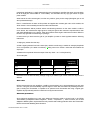
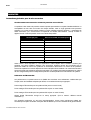
Important notice concerning High Sound Pressure Levels
Exposure to extremely high noise levels may cause a permanent hearing loss. Individuals vary
considerably in susceptibility to noise-induced hearing loss, but nearly everyone will lose some hearing if
exposed to sufficiently intense noise for a sufficient time. The U.S. Government’s Occupational and
Health Administration (OSHA) has specified the following permissible noise level exposures: Sound
Duration Per
Day In Hours
Sound Level dBA, Slow Response
8
90
6
92
4
65
3
97
2
100
1½
102
1
105
½
110
¼ or less
115
According to OSHA, any exposure in excess of the above permissible limits could result in some hearing
loss. Ear plugs or protectors to the ear canals or over the ears must be worn when operating this
amplification system in order to prevent a permanent hearing loss, if exposure is in excess of the limits as
set forth above. To ensure against potentially dangerous exposure to high sound pressure levels, it is
recommended that all persons exposed to equipment capable of producing high sound pressure levels
such as this amplification system be protected by hearing protectors while this unit is in operation.
TDcontroller use
Performance, sound quality and reliability of these speaker systems are entirely dependent on proper
setup and use of the appropriate TDcontroller: We strongly recommend that all new users carefully read
this manual with regard to the specific setup and use of the TDcontroller.
Analogue PS8 TDcontroller for PS8 systems (with or without LS400).
Analogue PS10 TDcontroller for PS10 systems (with or without LS500).
Analogue PS15 TDcontroller for PS15 systems (with or without LS1200).
NX242 Digital TDcontroller set on the appropriate set-up (See “NX242 User Manual”)
These controllers are not interchangeable. Each one is precisely matched to the corresponding cabinets.
Excepted NX242 that covers the entire NEXO range.
PS SERIES MANUAL REV3 10/10/05
P.6
LOUDSPEAKERS
___________________________________________________________________________________________________
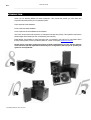
PS15Bass use
The PS15Bass is a passive cabinet that uses the same signal as the PS15. It
should therefore be connected in parallel with the PS15. You can use the
same controller for both cabinets; both will be equally protected. If you are
using the active mode of the PS15 the PS15Bass should be plugged into the
LF channel of the PS15 (1+/1-); a short adapter will be required (wired from
1+/1- of the PS15 to 2+/2- of the PS15Bass).
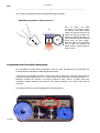
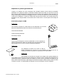
Speaker Wiring
The loudspeakers are connected with Speakon NL4FC plugs (not supplied).
A wiring diagram is printed on the connection panel located on the back of each cabinet.
The 4 pins of the 2 Speakon sockets identified in / out are connected in parallel within the enclosure.
Either connector can be used when connecting amplifiers and also to link to an additional PS cabinet and
optional LSub (if present). This way, a single 4-conductor cable can connect the amplifier rack to 1 or 2
PS plus 1 LSub.
PS SERIES MANUAL REV3 10/10/05
P.7
LOUDSPEAKERS
___________________________________________________________________________________________________
On the PS8, LS400, PS10, LS500, PS15 (used in passive mode), PS15 Bass and LS1200, the
connectors are wired as follows:
Speakon Connector
Signal
Pin 1+
Ö
SubBass + (optional)
Pin 1-
Ö
SubBass - (optional)
Pin 2+
Ö
Main PS system +
Pin 2-
Ö
Main PS system -
An additional Speakon connector on the PS15 connection panel is identified as 2 WAY ACTIVE; it is
reserved for operation in active mode (bi-amp, requires the NX242 Digital TDcontroller) and wired as
follows:
Speakon Connector
Signal
Pin 1+
Ö
PS15 LF +
Pin 1-
Ö
PS15 LF -
Pin 2+
Ö
PS15 HF +
Pin 2-
Ö
PS15 HF -
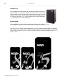
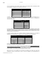
Selecting a cable consists of calculating the correct cable section (size) in relation to the load impedance
and the required cable length. Too small a cable section would increase its serial resistance; which would
induce power-loss and response variations (damping factor).
The following table indicates, for 3 common sizes, a cable length with a maximum serial resistance equal
to 4% of the load impedance (damping factor = 25).
Cable Section
Maximum Length
Impedance = 8 Ohms
Impedance = 4 Ohms
1,5 mm² [AWG # 14]
12 m [40 ft]
6 m [20 ft]
2,5 mm² [AWG #12]
20 m [64 ft]
10 m [32 ft]
32 m [104 ft]
16 m [52 ft]
4 mm² [AWG #10]
Initial Setup Precautions
When first powering up a system including brand new cabinets, NEXO recommends a gradual, minimum
power ramp up period of one hour. This allows the loudspeaker components to stabilize during the very
first hours of usage. This is particularly true for adhesives within the speakers' moving assemblies.
In all cases it is advisable to connect the loudspeakers only after all the other system components have
been wired and are operating correctly. This is particularly important for amplifiers and the TDcontroller. It
is good practice to turn down all the amplifiers' gains before connecting the cabinets and to turn them on
again individually with a medium level music source fed into the system. The Sense LEDs of the
PS SERIES MANUAL REV3 10/10/05
P.8
LOUDSPEAKERS
___________________________________________________________________________________________________
corresponding TDcontroller channel should light up accordingly. This will help to locate wiring errors,
particularly Left to Right or LF to HF Sense line channel inversions which would disable the TDcontroller
protection circuits and may invalidate the warranty.
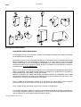
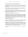
Asymmetrical Horn Configuration
Principle
The Asymmetrical Dispersion Constant Directivity horn is an important feature of the PS Series. This
concept was previously only available for highly specialized applications; in the general purpose PS it is
fully exploited thanks to a practical design that makes user configuration of the horn practical and quick.
The proper configurations of the horn for two common applications are shown below. All 4 positions of
the horn are possible and can be useful for specialized applications such as complex arrays, systems
designed with CAD software and stage monitoring.
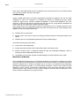
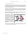
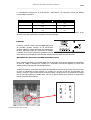
The specific dispersion of the PS8, PS10 & PS15 horn can be seen on figure 1 ("front of house"
configuration):
As seen on the side view, vertical coverage is narrower above horn axis (+25°) than below (-30°).
As seen on the front view, horizontal coverage is narrower above horn axis (50° Horizontal for +25°
Vertical) and wider below (100° Horizontal for -30° Vertical). Between these two extremes horizontal
coverage varies according to a specific law; on axis (0° Vertical) coverage is 75° Horizontal.
Access to the horn for configuration and checking is easily made by removing the front grille (pull gently
the sides of the grille to disconnect the press-stud fixings). To modify horn orientation, remove the four
Allen 4 metric or TORX TX25 screws (depending of model and age of the cabinet) that hold the horn in
place. A sticker on the wide dispersion side of the horn shows the correct orientation for wedge
monitoring and front of house applications: you simply position the indication on the desired side. The
arrow indicates the wide dispersion.
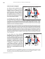
« Front of house » Configuration
50˚
Good coverage of audiences often requires a
conflicting combination of wide coverage ("shortthrow") for the closest listeners (below cabinet axis)
and narrow coverage ("long-throw") for distant areas
(on or above axis). The PS Series horizontal horn
coverage varies from "short-throw" to "long-throw"
along the vertical axis to precisely match these
practical requirements in a single system. For the
100˚
majority of applications, the asymmetrical horn
should be used with its "wide" dispersion side
directed towards the floor (as shown by the arrow) but all four cabinet orientations are usable.
PS SERIES MANUAL REV3 10/10/05
+25˚
-30˚
P.9
LOUDSPEAKERS
___________________________________________________________________________________________________
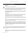
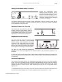
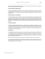
« Stage Monitor » Configuration
+3
0˚
100˚
-2
5˚
For stage monitors the required coverage
is always wider when performers are
close to the wedge (above the horn axis)
than when they move away from it (below
the horn axis). For floor monitor use the
horn must be rotated with its "wide"
dispersion side directed towards the top
of the cabinet (as shown by the arrow) in
wedge position as shown in the above
figure. The specific dispersion pattern, the
2" driver and the very high power handling
all contribute to the exceptional
performance of the PS15 as a wedge
monitor.
50˚
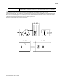
Active / Passive configuration (PS15 Only)
Switching from passive (factory setting) to active requires the use of the NX242 Digital TDcontroller and
modifications to the PS15 cabinet.
Unscrew the PS15connector plate at the rear of the cabinet (TORX 20 or Allen 2.5) and rotate the 6-pole
connector through 180° from socket « P » to socket « A ». Replace the connector plate, taking care to
remove the plastic blanking plug in the 2 WAY Active Speakon connector. It is strongly recommended to
blank off the two PASSIVE Speakon connectors with blanking plugs to prevent any cabling errors at a
later stage.
See also « Speaker Wiring » section page 6.
PS SERIES MANUAL REV3 10/10/05
P.10
LOUDSPEAKERS
___________________________________________________________________________________________________
SubBass Use (optional)
General Recommendations
The SubBass section of the TDcontroller is monophonic (the Left and Right channels are summed at the
input of the Controller). In a Stereo SubBass installation using 2 TDcontrollers, bear in mind that when
only one Controller input is used, this will lower the gain of the Sub Output by -6 dB (as the nominal level
is calculated for a 2 input use). You can either increase the gain setting of the LSub with the front panel
level control or use a Y adapter to feed both inputs of the controller with the same signal. A switch inside
the Analogue TDcontroller allows this setting to be made internally. (See “Sub jumper” page 21 )
For best results the LSubs should be positioned as close as possible to the PS loudspeakers and aligned
with respect to the audience. This helps to avoid interference near the crossover point.
Although sometimes in conflict with the above recommendation, LSubs' low frequency performance is
enhanced if multiple subs are grouped together. This also applies to Stereo installations using mono
LSub output where left and right Subs can be grouped together in the center for best effect.
The nominal efficiency data for LS400, LS500 and LS1200 and the standard Sub level settings on the
TDcontroller are for LSubs positioned on the floor (half-space). For other system configurations, and
particularly for « flying » subs, the low frequency sound pressure can be -3 to -6 dB lower. This can be
compensated for by a higher setting on the LSub output level control and/or by adding more SubBass
units.
Accessories
SAFETY recommendation for all accessories
Always inspect all components for damage before assembly. If you suspect that any of the
components are defective DO NOT USE THE AFFECTED PARTS.
Carefully read the assembly instructions shipped with each accessory.
Secondary safety steels must be installed once the system has been flown to operating height.
Secondary steels must be fitted irrespective of the local safety standards applicable to the territory.
When deploying the flying accessories, always wear protective headwear, footwear and eye
protection.
Do not allow inexperienced persons to handle flying systems. Installation personnel should be
PS SERIES MANUAL REV3 10/10/05
P.11
LOUDSPEAKERS
___________________________________________________________________________________________________
trained in loudspeaker flying techniques.
Ensure that motor hoists, hoist control systems and ancillary rigging components are currently
certified as safe and that they pass a visual inspection prior to use.
Ensure that public and personnel are not allowed to pass beneath the system during the installation
process. The work area should be isolated from public access.
Never leave the system unattended during the installation process.
Avoid, when possible, flying cabinets over areas where the audience has access.
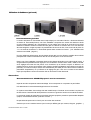
Stand, Mast & U Coupler
PS8, PS10 and PS15 have a built in 35 mm (1 3/8”) diameter stand adapter. Cabinets can be positioned
directly on a general-purpose speaker stand or on a mast inserted in the stand adapter fitted on top of the
LS400, LS500 & LS1200. The U-Coupler accessory allows positioning and relative rotation of two
cabinets arrayed side by side on top of the mast or on a speaker stand. The mast and U-coupler for the
PS8 and PS10 are available as options. For safety reasons the use of this U-coupler with the PS15
cabinet is not recommended.
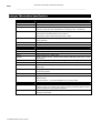
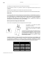
PS10 & PS15 Flying rails & Rings
PS10s and PS15s are equipped with steel anchor plates
(standard) that can be fitted with the following fittings (optional):
Top: 6 position aircraft-flying rail. (9 for PS15)
Bottom: two single position round aircraft flying rails.
(Two 3-position aircraft flying rails for PS15)
These rails are supplied as part of optional flying kits containing all
necessary screws and 4 single stud aircraft flying rings. Heavyduty double stud flying rings can be used in all rails except the
bottom PS10 points. Installation requires a metric N°5 Allen key or
TORX 30 (to remove the original back plate screws) and a metric
N°4 Allen key/ TORX 30 to fit the rails.
Vertical orientation of cabinets is a function of ring position in the top rail. It is imperative for security
reasons to use two rings per rail (left figure) linked to two independently fixed straps. Ring B will also be
used to stabilize the cabinet rotation and reduce the angle given by the master ring A. Nominal vertical
angles relative to the position of ring A (without the influence of ring B) are as follows:
Position
PS SERIES MANUAL REV3 10/10/05
PS10 Angles
PS15 Angles
1
-17°
2
-12°
-20°
-16°
3
-7°
-12°
4
-2°
-8°
5
+3°
-4°
6
+8°
0°
7
NA
+4°
8
NA
+8°
9
NA
+12°
P.12
LOUDSPEAKERS
___________________________________________________________________________________________________
Omnimount® style clamps
The back and the bottom of the PS10 is equipped with internal anchor points (M8 metric) to the
Omnimount® 100 Series spacing standard. This is particularly convenient when cabinets must be
installed permanently in a horizontal or vertical position. To remove the original screws an N°4 metric
Allen key/TORX25 is required. Please note that the Omnimount 100 series is not rated for the weight of
the PS15. Do not use this accessory with this cabinet without a second proper safety point.
PS8 Accessories
FS0081-001
This accessory is designed to be mounted directly onto the PS8 cabinet
surface. It provides 2 M10 captive nuts that allow the following
accessories to be fitted: (not supplied in this kit)
Standard lighting hook/CLAMP
M10 lifting eye bolt
DIN Pivot (TV spigot)
FS0081-002
This accessory provides 2 welded M5 nuts and 1 welded M10 nut. (It should
always be used along with the FS0081-001.) This adapter allows the cabinet to
be fixed on the wall, ceiling or on a stand using the FS0081-003
FS0081-003
This adapter is designed for use with the PS8 cabinet. It allows for Horizontal
mounting of the cabinet on a stand or a mast (∅35mm). It can be used along with
other accessories or it can be fitted directly to the cabinet.
SA0081-001
This safety accessory kit contains:
o
1 x 30cm steel sling (plastic covered) + 1 x speed nut & Bolt. Used to provide secondary safety
for the front grille.
Fitting the safety wire is very simple and involves bolting it to the grille assembly and fixing the other end
to one of the HF horn mounting bolts. Nexo recommend that this safety wire is always used when the
PS8 cabinet is to be used in public areas above head height, for example when the cabinets are to be
flown or wall mounted. It is the responsibility of the user to install the safety wire in all such situation.
PS SERIES MANUAL REV3 10/10/05
LOUDSPEAKERS
P.13
___________________________________________________________________________________________________
Use & Maintenance
Checking the PS10 & PS15 internal fuses
The following paragraph concerns only the PS10 and PS15 cabinets, since the PS8 is fitted with a resettable fuse that does not require maintenance.
The function of these fuses is to protect the passive crossover against overheating if a speaker
component is accidentally disconnected or fails open circuit. They can also protect amplifiers from current
overloading in such an event. To preserve sound quality the fuses are not inserted in series with the
loudspeaker components themselves and thus do not protect them directly. If a loudspeaker component
is accidentally disconnected or fails open circuit and needs repairing, the fuses must be checked. Their
status can be verified visually and they are easy to replace.
Caution: a broken fuse will degrade sound quality and endanger the loudspeaker components but the
cabinet will still operate. The order of the passive filter will be reduced; this will lead to an improper phase
matching of the two drivers, and in the case of the HF driver to potentially dangerous excursion. It may
not immediately be noticeable. Incidents that can cause fuse breakage require the cabinet to be opened;
it is good practice to always check the fuses in such cases.
PS15: These fuses are of the common "automotive" type (ATO Blade type) with standard values (5A &
10A) on the passive crossover and 5x20 temporized fuse (T500mAL250V) on the ICN circuit.
PS10: These fuses are of the common "automotive" type (ATO Blade type) with standard values (3A &
10A)
The fuses are located as follows:
PS10 & PS15 On the PCB of the internal passive crossover located behind the connector panel. Release
the 4 or 6 screws holding the connector panel (Allen metric 2.5 or TORX20) and disengage the panel &
crossover assembly (an upward rotation movement is required).
PS SERIES MANUAL REV3 10/10/05
P.14
LOUDSPEAKERS
___________________________________________________________________________________________________
PS15: On the ICN PCB located near the compression driver. Remove the HF horn; the PCB is located
on the side and is fixed to the side of the cabinet.
Troubleshooting
Simple troubleshooting does not require sophisticated measurement equipment and can be easily
undertaken by users. The technique is to segment the problem by identifying the faulty system
component: signal source, controller, amplifier, loudspeaker or cable? Most installations are multichannel; it is often the case that one channel works and others do not. Trying different combinations of
system elements can usually help to isolate and locate the fault.
Some cabinet faults can be quite easily located and corrected by the user. A simple sweep with a sine
wave generator can be very helpful but it MUST be made at a fairly low level to prevent damage to the
speakers: A sine wave sweep can help find:
Vibrations due to loose screws.
Air-leak noises: check that no screws are missing, particularly where the accessories attach to the
cabinet.
Vibrations due to a front grille badly positioned on the quick release fixings.
Some faults require opening the cabinet:
Fuses (refer to above paragraph)
Foreign object that has fallen into the cabinet after repair or through the ports.
Internal connection wires or absorbing material touching the loudspeaker diaphragm: check by
removing the bass loudspeaker (Allen metric N°4).
Loudspeaker not connected or phase reversed following a previous inspection, test or repair.
Maintenance & Warranty
Nexo loudspeakers and electronics are covered against defects in workmanship or materials for a period
of two (2) years from the original date of purchase. At the discretion of Nexo, the defective item will be
repaired / replaced with no charge for materials / labor. The item to be repaired must be adequately
packaged and dispatched, prepaid, to an authorized Nexo distributor / service center. Repair by other
distributors / service centers or personnel not authorized by Nexo shall void the warranty. This Nexo
warranty does not cover cosmetics or finish. It does not apply to any items that have failed due to user
abuse, accidents, modifications or any type of misuse.
PS SERIES MANUAL REV3 10/10/05
ANALOGUE TDCONTROLLER SETTING-UP ADVICE
P.15
___________________________________________________________________________________________________
Analogue TDcontroller Setting-Up Advice
Mains Power
WARNING ! THIS APPLIANCE MUST BE EARTHED.
The green and yellow wire of the mains cord must always be connected to an installation safety earth or
ground. The earth is essential for personal safety as well as the correct installation of the system, and is
internally connected to all exposed metal surfaces. Any rack framework into which this unit may be
mounted is assumed to be connected to the same grounding circuit. (see also p.15)
NEXO TDcontrollers don’t provide a mean to switch off the unit from the front panel. As they are intended
to be rack mounted the back panel is not accessible during use. Therefore it is left to the user to provide a
disconnection mean readily operable.
Voltage setting
NEXO TDcontrollers use a switch mode power supply (SMPS). This SMPS accepts universal AC power
input voltages in the range 90V to 264V, and requires no manual adjustment for voltages in this range.
Mounting the TDcontroller in a rack (Grounding, shielding & safety issues)
The TDcontroller is intended for rack mounting. The only accessible part during use shall be the front
panel of the TDcontroller. Any space above or under the TDcontroller shall be obstructed with a blank
panel.
The rack is a free grounding and shielding structure and it provides extra shielding. Therefore, it is
desirable that the screws used to fix the TDcontroller in the frame or rack provide an electrical contact
between the chassis of the TDcontroller and the rack.
The primary reason for grounding is safety. Conformance to the applicable requirements of the
authorities having jurisdiction is, of course, mandatory. However, grounding also has an impact on
electromagnetic compatibility. From the EMC point of view, it is desirable to have a low impedance
ground network, as a current flowing in the ground network will then produce low voltage in the network.
A low impedance network can be obtained using a multipoint ground scheme, with as many closed
ground loops as is economically possible.
Fuse
The fuse provided in the unit will not blow during normal operation. If the fuse blows the TDcontroller
has malfunctioned. This fuse must only be changed by NEXO certified service personnel. In any case
do not replace the fuse with a non-certified NEXO fuse, as this will invalidate the NEXO warranty.
CAUTION!
This servicing instruction is for use by qualified service personnel only. To reduce the risk of electric
shock, do not perform any servicing other than that contained in the operating instructions unless you are
qualified to do so.
PS SERIES MANUAL REV3 10/10/05
P.16
ANALOGUE TDCONTROLLER SETTING-UP ADVICE
___________________________________________________________________________________________________
Recommendations for wiring the sense lines
The impedance of the sense inputs of the TDcontroller are high, so currents are low and therefore light
duty cable can be used. If the TDcontroller is housed in the amplifier racks an unshielded cable may be
used.
If the TDcontroller is located remotely - at the mixing position - a shielded cable is recommended, without
using the shield as a conductor. The cable must be well protected from public access, as it carries
potentially dangerous amplifier voltage.
When one of the channels is not being used and the corresponding sense line is disconnected, cross talk
onto the inactive sense line may in some cases produce signals capable of causing the inadvertent
illumination of the Sense LED on that channel; although this has no effect on the internal operation of the
TDcontroller, it can be cured by short-circuiting the terminals of the inactive sense line.
Recommendations for wiring the audio outputs
The output stages can drive several amplifiers in parallel; however it is not advisable to work with loads of
less than 1kOhm(and strictly forbidden to drive less than 600Ohms). It is best to check the impedance
characteristics of the amplifier inputs - supplied by the manufacturer - to check how many amplifier
channels can be paralleled. Where precise information is not available (and taking 10kOhm as the
minimum value possible), ten channels in parallel per output is a sensible maximum.
Electromagnetic environments
The emission (this word describes all types of electromagnetic noise radiated by the equipment)
requirements which have been applied to Nexo’s TDcontrollers are the stringent requirements of the
”Commercial and light industrial environment” of the product family EMC standard for emission.
The immunity (this word describes the ability to cope with electromagnetic disturbance generated by
other items and natural phenomena) requirements that we have considered exceed those applicable to
the ”Commercial and light industrial environment” of the product family EMC standard for immunity. In
order to provide a further safety margin, we recommend that you do not operate the TDcontrollers in the
presence of electromagnetic interference exceeding half of the limits found in this standard.
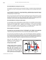
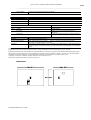
Analogue signal cables
Low Z
-
PS SERIES MANUAL REV3 10/10/05
3
+
2
1
PE
SHIELD
1
Analogue signals should be connected to
the input and output ports of the TDcontroller
via shielded twisted pair or starquad cable
fitted with XLR connectors on the
TDcontroller side. We recommend the use
of low transfer impedance cables with a
braided shield and a transfer impedance
below 10 mΩ/m. For the sense inputs, the
noise requirements are not as stringent, and
Amplifier
Low Z
Mixing Desk
1
3
3
+
2
PE
SHIELD
These two EMC standards are those
applicable to pro-audio equipment for the
implementation of the ”EMC directive”.
1
2
-
+
3
-
PE
2
+
Low Z
Low Z
IN
TDcontroller
OUT
Safety
Ground
P.17
ANALOGUE TDCONTROLLER SETTING-UP ADVICE
___________________________________________________________________________________________________
any kind of twisted pair cable will be adequate.
The TDcontroller is intended to be used with symmetrical (balanced) sources (for instance a mixer) and
symmetrical loads (for instance a power amplifier (see figure). You can see that the TDcontroller provides
a low impedance path between pin 1 of its XLR connectors and its chassis. The TDcontroller can sustain
high current in pin 1 without degradation of output noise. We recommend that the sources and loads you
use have the same desirable characteristics.
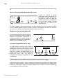
It is sometimes claimed that connecting cable shield at both ends creates ground loops, and that the
current flowing in such loops will produce noise. This is not the case for most professional audio
equipment. In short, there are two kinds of loops in which voltages are present: the loops formed by
signal wires, and the loops formed by grounded conductors, among which are protective earth
conductors (PE) and signal cable shields.
When a cable shield is grounded at both ends, a loop is closed, and the resulting current causes a
reduction of the voltage induced on signal lines. This effect is what the cable shield is intended to
produce, since this is how it protects your signal from magnetic fields.
Amplifier
Low Z ?
Mixing Desk
0V
Low Z ?
3
2
1
?
1
3
3
+
2
PE
SHIELD
1
-
+
SHIELD
If you are using an asymmetrical
(unbalanced) source, it is best to use a
shielded twisted pair and to connect wire 3
of the cable to the shield at the source
output end (see figure). This technique
prevents noise currents flowing on the
return path of the signal. If you are using
an amplifier with an asymmetrical
(unbalanced) input, it is best to use a
shielded twisted pair, and to connect wire 3
at the TDcontroller end only, as shown in
Fig. 2. This keeps a good capacitance
balance for the signal, however noise
currents flow on the return path of the
signal. (Note that this is only acceptable for
a short cable).
1
2
-
+
3
-
PE
2
Safety
Ground
+
Low Z
Low Z
IN
TDcontroller
OUT
If you are using a symmetrical (balanced) source or amplifier which is prone to become noisy when a
current of less than 100 mA at the mains frequency (50 Hz or 60 Hz) is sourced into pin 1 of its XLR
connectors, you might consider opening the ground loops.
PS SERIES MANUAL REV3 10/10/05
P.18
ANALOGUE TDCONTROLLER USER GUIDE
___________________________________________________________________________________________________
Analogue TDcontroller USER GUIDE
Read before use
Each Analogue TDcontroller is designed to be used with its proper set of speaker cabinet (PS8 / LS400,
PS10 / LS500; PS15 / LS1200). They are not interchangeable. Its main functions are:
To optimize the response of the system
When operating with the LS SubBass system (optional), splitting the stereo (2 channel) signal into 2
frequency bands (PS main system and LS SubBass system)
Active protection of the cabinets by dynamic audio signal processing (Temperature and
Displacement servo control)
Reduction of amplifier overload (Peak limiter function)
Analogue TDcontrollers also feature:
Stereo operation (2 independent channels) for the main system
Global switchable output level
Adjustable level on the SubBass channel
High CMRR input stage and High current drive output
Compensation of power compression effects on the system response curve.
The Analogue TDcontroller is designed to be inserted between the Audio source (console, preamplifier,
etc.) and the power amplifier.
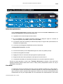
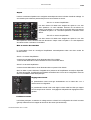
Front Panel
Most front panel functions and indicators are located inside 2 distinct windows: left-hand areas relate to
functions and indicators dedicated to the optional Sub-bass section, while right-hand window contains
indicators concerning servo control operation for the PS cabinets.
For more technical details about servo control operation and internal electronic processing, please refer
to section “TDcontroller REFERENCE GUIDE.” Page 22.
PS SERIES MANUAL REV3 10/10/05
P.19
ANALOGUE TDCONTROLLER USER GUIDE
___________________________________________________________________________________________________
Turning the LS channel Overlap / Crossover
Pushing the CONFIGURE button
modifies the high pass filtering. It does
not affect the sub output, which will
always be a filtered sub signal. (This is
therefore not a Sub on/off button). In the
« Overlap » position, the PS is exploited
to its maximum capability.
This position should be used if the system is being used without a LSub. It can also be used with the
LSub; In this case, there will be a boost in the crossover area. The « Cross over » position is generally
recommended when using the LS400.
Adjusting the LSub level (Sub Level)
The potentiometer adjusts the level of the LSub
channel, a range of 12 dB allows a variety of
configurations and application conditions to be
accommodated. Center position of the knob is
calibrated for 1 LSub used with 2 distant PS.
Amplifier & Protection indicator
The bicolor green/red AMP LED indicates signal
presence at the sense input of the concerned
channel, allowing visual confirmation of the return
connection of the Sense cables from the amplifier
output. The LED is flashing red, when the Peak
limiter is acting, reducing excessive peak voltage or
levels capable of overloading the channel amplifier.
The yellow VLF LED indicates that displacement
protection for the LSub are engaged on the SubBass channel. The temperature protection is not
monitored.
On each side of the PS main system window, yellow TEMP and DISP LEDs indicate when protection has
been activated (temperature or displacement control) for the LF (the HF drivers temperature protection is
not monitored).
Peak Limiter adjustments
The Analogue TDcontroller features two independent peak limiter trims (one for the LSsub amplifier
section, one for the PS amplifier section), which allows the peak limiter to be set to limit the maximum
power of the amp (without affecting the protections threshold). The peak limiter has no real cabinet
protection functions; it must be tuned to avoid overdriving the amp that in turn can generate obvious
clipping noise.
To set the peak limiter to the correct value, either turn the trimmer clockwise until the red LED lights at the
same time as the amp’s clipping LED, or use the graduation (power value given for 8 load).
PS SERIES MANUAL REV3 10/10/05
P.20
ANALOGUE TDCONTROLLER USER GUIDE
___________________________________________________________________________________________________
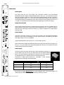
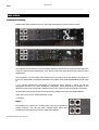
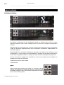
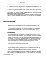
Rear Panel
The audio inputs are two 3-pin female XLR connectors located in the area labeled
BALANCED INPUTS. Signal is applied between pins 2 and 3, pin 1 is connected to ground.
When the Controller is linked to a signal source with balanced outputs, the XLR connections
are simply wired pin to pin (1 to 1, etc.). As a result of the balanced nature of the outputs (and
providing that balancing is respected by way of the connection to the amplifier), there is no hot
or cold pin - the Analogue TDcontroller being neutral regarding the polarity of the signal.
BALANCED INPUTS
RIGHT
LEFT
Audio Inputs
The 3-position output level switch is used to match the processor gain to the amplifier gain for
optimum signal to noise ratio. The three gain values available are +6, 0 or -6 dB. For minimum
noise floor the -6dB setting should be chosen, for maximum headroom the +6dB position
should be used.
BALANCED OUTPUTS
Audio Outputs
The audio outputs are the three 3-pin male XLRs located in the area labeled BALANCED
OUTPUTS. The channel corresponding to each output connector is identified by the labels
Left, Right and Sub L+R (mono SubBass).
SUB L+R
RIGHT
LEFT
+6dB
0dB
OUPUT
LEVEL
-6dB
Output Level Switch
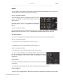
Signal is applied between pins 2 and 3, pin 1 is connected to ground.
+ LEFT -
Sense inputs
+ RIGHT -
(from amp terminals)
+ SUB -
The sense inputs of the three channels (left, right and SUB) are arranged on a
six-pole barrier strip set into the rear panel within the area labeled SENSE
INPUT. The Sense inputs are intended for connection to the output signals of
the amplifiers driving one cabinet of each the channels being used.
115 - 230V
50 - 60Hz 10W
CAUTION !
To reduce the risk of electric schock
grounding of the center pin
of this plug must be maintained.
10CE
SENSE INPUT
CAUTION !
Sense line must be connected
for speaker protection.
EARTH
LIFT
When used with an amplifier with balanced inputs, the wiring of the output XLR is simply pin to
pin (1 to 1, etc.), the polarity of the signal being preserved if the source connected to the input
is also balanced (see previous section).
Connection is made via the female part - removable - of the connector
(supplied with the Controller) as outlined below:
Channel
PS Left
4004
LS
s.n:
PS8 TDcontroller
MADE IN FRANCE
03105
PS Right
Amplifier Output Terminal
Barrier strip connector
- (black)
Ö
pin 1 (figure)
+ (red)
Ö
pin 2
- (black)
Ö
pin 3
+ (red)
Ö
pin 4
- (black)
Ö
pin 5
+ (red)
Ö
pin 6
Input sense connection MANDATORY for proper operation of the servo-control system, the
cabinets will NOT BE PROTECTED if the sense lines are unconnected.
PS SERIES MANUAL REV3 10/10/05
P.21
ANALOGUE TDCONTROLLER USER GUIDE
___________________________________________________________________________________________________
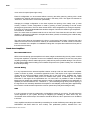
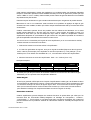
Earth Lift
The push button labeled « Earth Lift » allows connection
(depressed position), or disconnection (out position)
between the signal ground and the mains earth, which is
itself linked to the chassis. Using this button may help to
eliminate hum due to ground loops created in the system.
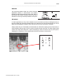
Sub jumper
In certain applications you may wish to disable the mono summation (but keep the 6dB gain boost) on
the sub channel. By moving the internal jumper ST1 inside the unit, the sub channel will only use the
Right input (with 6dB gain to keep the same sub level when the mono summation is enabled).
Always ensure that your TDcontroller is disconnected from main before opening the unit. Remove the 3
screws fastening the top panel. The ST1 jumper is located near the Input XLR. The PIN1 being the PIN
closest of the Input XLR. Strap PIN 1-2 (B in the drawing) in order to drive the sub only from input R.
Strapping Pin 2-3 (labeled A, factory default) will provide the summation of channel R&L.
1
2
3
A
PS SERIES MANUAL REV3 10/10/05
B
P.22
TDCONTROLLER REFERENCE GUIDE
___________________________________________________________________________________________________
TDcontroller REFERENCE GUIDE
Linear section
The characteristics of the linear section are independent of signal level, as opposed to the servo control
functions described in next paragraph.
Subsonic and VHF filtering
Low and high-pass filters are used to remove signals out of the usable frequency range, eliminating suband ultra-sonic components that could possibly degrade the performance of the Controller and amplifiers.
These filters are optimized to realize the overall target system response.
Equalizing acoustical response
This equalization section provides the required correction to obtain a flat system response, as the
cabinets are acoustically designed for maximum efficiency in the whole frequency range. Active rather
than passive attenuation allows amplifier voltages to be lowering for a given output SPL and therefore
increases the maximum SPL achievable with the same amplifier.
Active equalization also extends system bandpass, especially at low frequencies where acoustical
performance is limited by cabinet size.
PS / LSub Cross-Over
From input signals summed together, the resulting mono signal is low-pass filtered to feed the SubBass
channel. When the channel is turned on (LSub On), main channels (Left & Right) high-pass filters are
reconfigured to filter out signal components below the crossover frequency. Slopes and other filter
characteristics are optimized using techniques optimized for the actual acoustical data of each driver.
Servo Control section
Servo control of the PS TDcontroller is intended to work with amplifier return signals present at the Sense
inputs (monitored by front panel LEDs).
VCAs and VCEQs
Each of the 3 Audio channels (Left, Right and SubBass) contains two voltage controlled elements driven
by servo signals:
One operates on the whole frequency range (wide band VCA).
The other elements work selectively as dynamic equalizers (LF-VCEQ & HF-VCEQ).
Depending on the nature and origin of the servo signals, either one or the 3 combined elements is used
to process the Audio signal. This feature allows more efficient processing while reducing audible effects.
PS SERIES MANUAL REV3 10/10/05
TDCONTROLLER REFERENCE GUIDE
P.23
___________________________________________________________________________________________________
Displacement control
The signal from the sense input is fed through a shaping filter producing a signal proportional to the voice
coil displacement. This control signal is compared to a fixed value and if exceeded, the LF-VCEQ is
activated with very short attack time to reduce speaker excursion.
Temperature control
Sense input is fed to a shaping filter to create a voltage proportional to the instantaneous voice-coil
current. The signal is integrated over time to simulate heat buildup in the specific driver. When the
resulting voltage exceeds a preset threshold, the VCA is activated to limit the voice coil temperature
within its safety range. Power compression is also simulated by lowering the high frequencies when
temperature protection is acting on the bass loudspeaker.
Dynamic control
To reduce audible « pumping » effects due to very long time constants of temperature detection signals,
an alternate integration is also processed with a shorter time constant. Whilst anticipating the temperature
protection and reducing its unwanted effects, action of this signal also improves dynamics control.
Peak Limiter
The above mentioned devices provide reliable protection against potential speaker over-heating and
over-excursion. Nevertheless driving the cabinets at very high peak voltages (with oversized amplifiers)
as well as delivering distorted signals might be dangerous for the speakers. The Peak limiter is both
useful for:
Maintaining good sound quality at high levels (it will reduce amplifier distortion).
Increasing protection reliability (limiting peak voltages to levels that speakers can permanently withstand,
and reducing the occurrence of subsonic signals delivered by overloaded amps)
PS SERIES MANUAL REV3 10/10/05
P.24
AMPLIFIERS
___________________________________________________________________________________________________
AMPLIFIERS
PS8Amp & PS10Amp
Please note that this equipment is not UL approved and therefore not sold on the US market.
The PS8Amp and PS10Amp are power amplifiers tailored for PS8 and PS10 system and their respective
LS400 & LS500 sub bass requirements. Their structure and power being identical, they share the same
specifications:
Total integration of a TDcontroller (with internal sense connection) which specifications are identical of
those of an independent TDcontroller described in the chapter “TDcontroller REFERENCE GUIDE” page
22
2 or 3 channel instantaneous configuration via front-panel switch, allowing a 3-WAY use with the
appropriate sub bass or a 2 WAY (wideband) configuration. Power delivered by the amplifier is thus
optimized for the proper configuration. Speaker wiring of each cabinet is also automatically re-assigned.
All connections and controls located on the front panel including mains fuses and voltage selection.
Super silent, back to front, variable speed fan cooling.
3 units high.
Inputs
Each balanced Line Input has a chaining male connector for operation of
multiple PSAmps. The L&R link switch simplifies Mono wiring when
independent PSAmp stacks are used for stage Left and Right.
PS SERIES MANUAL REV3 10/10/05
AMPLIFIERS
P.25
___________________________________________________________________________________________________
Outputs
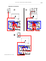
The two Speakon connectors are automatically configured with a visual indication of the current wiring.
Configuration can be made while the system is operating.
Sub On = 3 amplifier channels :
The two PS Stereo channels are assigned to poles 2+ and 2on the L & R Speakons. A single PS LED lights up on each
Stereo channel.
The LSub channel is Mono L+R summed and assigned in
parallel to poles 1+ and 1- of both Speakons. The LS LED
lights up.
Sub Off = 2 amplifier channels:
The two PS Stereo channels are assigned to poles 2+ and 2- on the L & R Speakons. Two PS LEDs are
lighted on each channel. Poles 1+ and 1- of both Speakons are disconnected. The LS LED is off.
Sub Bass Channel
The LSub On Switch automatically reconfigures the PSAmp according to its two operating modes :
Sub On = 3 amplifier channels :
2 x 430 Watts into 8 Ohm channels feed two PSs in Stereo.
1 x 850 Watts into 4 Ohm channel feeds the LSub in Mono L+R.
Sub Off = 2 amplifier channels :
2 x 850 Watts into 4 Ohm channels feed two or four PS10s in Stereo.
The 1700 W power capability of the PSAmp is always used whether or not
the LSub is operated. The Sub amplifier channel is rerouted to the PS10s in
the Sub Off operating mode. In both cases the installation is always
stereophonic.
Level control
The Level control operates simultaneously on all 2 or 3 channels according to
configuration.
The LSub Level control adjusts the level of the LSub relative to the PS when Sub is On.
Fuses and Mains
115/230 V mains Voltage selection, Main fuses and Earth-Lift configuration are located under the safety
PS SERIES MANUAL REV3 10/10/05
P.26
AMPLIFIERS
___________________________________________________________________________________________________
cover on the front panel (lower right corner).
Earth-Lift configuration can be accessed without removing the safety panel by pushing with a small
screwdriver the earth lift switch through two tiny holes in the safety cover. The upper hole switches to
“Ground on”, the lower hole to “Ground off” (earth lifted).
Changing the Voltage configuration or the fuses requires the opening of the safety cover (2 outer
screws). 115/230 V mains configuration is made by pushing a switch (according to the silk screen
painting) through two holes. The main fuses are the same in both configurations (no change is required).
If the event of a main fuse failure both fuses shall be changed. The fuses are 5x20mm type temporized.
Fuse reference: T6.3AH250
Note: Two other fuses are located inside the unit on the PCB. Those fuses should never fail in normal
operation. In the event of a failure do not replace those fuses yourself, as something else could be faulty.
Contact an authorized dealer.
The mains power cable can be located on the front or on the back of the PSAmp. Changing the mains
cable from the front to the back shall be made by an authorized dealer. No other control or connection
exists on the back of the amplifier. At installation nothing else is required than sufficient air flow path on
the back of the PS10Amp.
Stand alone Amplifiers
Recommended Power
NEXO recommends high power amplifiers in all cases, budget constraints being the only reason to select
lower power amplifiers. If a problem occurs on an installation without protection, the use of a lower power
amplifier generating half their rated output power (-3dB) will not prevent possible damage. This is due to
the fact that the RMS power handling of the weakest component in the system is always 6 to 10 dB lower
than the amps' rating
Current Rating
It is very important that the selected amplifier behaves correctly under low load conditions. A speaker
system is reactive by nature, on transient signals like music it will require much higher instantaneous
current than its nominal impedance would indicate (four to ten times more). Amplifiers are usually
specified by their continuous RMS power into resistive loads (which is irrelevant); the only useful
information in that regard is the specification into a 2 ohms load. It is possible to make an amplifier
listening test by loading the amplifier with twice the number of cabinets considered for the application (2
speakers per channel instead of one, 4 instead of 2…) and modulating at high level (onset of clipping). If
the signal does not noticeably deteriorate the amplifier is well adapted (overheating after approximately
ten minutes is normal but thermal protection must not operate too quickly after starting this test).
Gain
It is very important to know the voltage gain of all amplifiers present in your set-up. This will ensure the
correct alignment of your system and may be obligatory (for reliability) in cases where only one
TDcontroller drives several amps. The tolerance should be about ±0,5 dB. In practice this can be difficult
to achieve:
Some amplifier brands have an identical input sensitivity for models of different power ratings (this means
DIFFERENT VOLTAGE GAIN for each model). This problematic practice, inherited from nonPS SERIES MANUAL REV3 10/10/05
P.27
AMPLIFIERS
___________________________________________________________________________________________________
professional applications, is easily detected when the manufacturer specifies the same input sensitivity
for all its range (like 775mV/0dBm or 1.55V/+6dBm). This translates into very high gain values on higher
power models.
Other brands do offer constant gain, but often only within a given product range (like higher gain on all
semi-professional amps).
Even if a manufacturer is aware of this problem and applies the constant gain rule to all its models, the
value chosen is not necessarily the same as other manufacturers.
Some manufacturers deliver products where manufacturing tolerance on the same model is ±1dB or
more. Worse, the manufacturer might agree to modify this gain at the customer’s request without clear
and visible identification on the device. Other amps feature internal gain switches that make it difficult to
know the amp gain without measuring or opening it.
In cases where you don't know the gain of your amplifier (or want to check it) please read the following
instructions.
1/ Unplug any cabinet from the amp
2/ With a signal generator feed a sine wave (freq. within the audio range, 1000Hz for example) Amplitude
Vin is not important (1V is rather convenient), u taking care not to choose a value that will overdrive the
amp input!
3/ Measure the Amplitude Volt at the output of the amp. Gain = 20 * LOG10(Vout/Vin)
Some examples:
Gain
20dB
26dB
32dB
Vin
37dB (1.4V
sensitivity /
1350Wrms)
0.1V
1V
2V
4V
7.1V
0.5V
5V
10V
20V
35.4V
1V
10V
20V
40V
70.8V
Remember that constant sensitivity settings will give you different gain values when the amp Power is
different.
Gain value
NEXO recommends low gain amplifiers: +26dB is recommended, as it is both adequately low and quite
common. This gain level considerably improves signal to noise ratio and allows all preceding electronic
gear, including the TDcontroller, to operate at an optimum level. Remember that using a higher gain
amplifier will proportionally raise the noise floor level by the same amount.
Advanced protections
Some high-end amplifiers may have some advanced functions similar to those found in the NEXO
TDcontrollers ("loudspeaker offset integration", "limiter", "compressor"...). These functions are not well
adapted to NEXO system requirements and may interfere with existing protection within the TDcontroller.
NEXO recommends disabling these functions.
PS SERIES MANUAL REV3 10/10/05
P.28
ANALOGUE TDCONTROLLERS SPECIFICATIONS
___________________________________________________________________________________________________
Analogue TDcontrollers Specifications
PRODUCT FEATURES
Audio Inputs
Two differential non floating L&R Audio inputs, 50 kOhm. Two XLR-3F connectors.
Sense Inputs
Three Amplifier Sense Inputs (PS L&R, LS). 400 kOhm. 6 Pole Removable Strip Terminal
Audio Outputs
Two L&R PS Audio outputs. Balanced, non floating, 51 Ohm. Two XLR-3M.
One Mono (L+R) LS400 Audio output. Balanced, non floating, 51 Ohm. One XLR-3M.
Controls
Gain switch (back panel), 3 positions : -6 / 0 /+6dB.
Peak Limiter trimmer (600W-200W/8 Ohms) for PS8 & 10
Sub Overlap / Crossover switch & Sub Gain Control (-/+ 6dB).
Indicators
LF speakers Protect Yellow LED's (Temp. & Disp), Power ON (green), Amp Sense & Peak
LED's (green/Red)
Dimensions
1U 19" Rack.
Weight :
2.9 kg (6.6 lbs) net
165mm (6.5") Depth
SPECIFICATIONS
Output Section
+22 /+16/+10 dBm typ. into 600 Ohm load. Back Panel switch on +6/0/-6dB respectively.
Input Section
Maximum input Level : 22dBu. CMRR 90dB @ 1kHz typ.
THD+N
0.05% @ 1kHz Typ. for +10dBm Output
Noisefloor
PS8TD -100 dBV PS10TD: -103dBV PS15dB: -98dBV for 0dB switch position (22 Hz - 22 kHz,
Dynamic Range
111 dB UnWeighted (THD+N at-60dBr sine wave @1kHz rel.max. output)
Crosstalk
104dB
UnWeighted)
Filtering & EQ.
L&R: 12dB/oct Low Pass, 12dB/oct High pass (crossover or overlap), 4 Parameter EQs. All
factory tuned
Protections
VCA temp. (SUB,LF & LF), VCEQ disp. (SUB & LF), Peak Limiter (all chanels), Power
compression regulation
Power Supply
Conformity
100-250 Volts (continuous operation), 50/60Hz. Power 9W. Peak Inrush current 0.5A. Earth-Lift.
Comply with safety objective of 73/23/EEC & 89/336/EEC directives. (EN60065-12/2001,
EN55103-1996).
CB scheme DK-8371, cULus 60065 AZSQ E241312, FCC part15 class B
SYSTEM OPERATION
Applicable Products
The PS8 TDcontroller is precisely matched to the PS & LS cabinets and includes sophisticated
protection systems. Use of either product without a properly connected Controller will result in
poor sound quality and may damage the components.
SubBass
Active two-way operation of the PS8 Loudspeaker with the LS Subwoofer is included in the
Analogue PS TDcontroller .
PS SERIES MANUAL REV3 10/10/05
PS8 & LS400 : SPECIFICATIONS, CURVES & DIAGRAMS
___________________________________________________________________________________________________
PS8 & LS400 : SPECIFICATIONS, CURVES & DIAGRAMS
SYSTEM SPECIFICATIONS
PS8 with PS8 TDcontroller
LSub 400 with PS8 TDcontroller
Frequency Response [a]
69 Hz - 19 kHz ±3dB
43 Hz - 120 Hz ±3dB
Usable Range @-6dB [a]
62 Hz – 20 kHz
40 Hz - 140 Hz
Sensitivity 1W @ 1m [b]
96 dB SPL Nominal - 94 dB SPL Wideband
99 dB SPL Nominal
Nominal Peak SPL @ 1m [b]
122 to 125dB Peak (for 200 to 500 W RMS Amp.)
128 to 131 dB Peak (300 to 700 W RMS Amp.)
HF Dispersion [c]
50° to 100° Hor. x 55° Vert. Rotatable Horn, 4 positions
-
Directivity : Q & DI [c]
Q : 10 Nominal
Crossover Frequencies
2.5 kHz Passive
Nominal Impedance
8 Ohms
6 Ohms
Recommended Amplifiers
200 to 500 Watts into 8 Ohms for 1 x PS8 per channel
400 to 1000 Watts into 4 Ohms for 2 x PS8 per channel
300 to 700 Watts into 4 Ohms
DI : 10 dB Nominal ( f > 1.8 kHz )
120 Hz Active through PS8TD
SYSTEM OPERATION
Electronic Controller
Dispersion configuration
Subbass
The PS8 TDcontroller is precisely matched to the PS8 & LS400 cabinets and includes sophisticated protection systems. Using
PS8 & LS400 without a properly connected PS8TD will result in poor sound quality and can damage the components. PS8 &
LS400 can also be used with the NX242 Digital TDcontroller.
After quick-release of the front grille from its fixings, the HF Horn can be rotated in 4 positions for dispersion configuration.
The PS8 can be used without optional LS400 Subbass. Active two-way operation with the LS400 is included in the PS8TD.
One LS400 matches 2 x PS8, additional LS400 may be used for enhanced effect.
PS8 are wired 2- & 2+ on Speakon connectors, LS400 on 1- & 1+. Loop through Speakons are present on both. Single
identical cables can thus be used to loop through combinations of up to 2 x PS8 & 1 x LS400 in no particular order.
Speaker Cables
PRODUCT FEATURES
PS8
Components : LF
1 x 8" (20cm) Shielded Neodymium 8 Ohms driver
1 x 12" ( 30cm ) long excursion 6 Ohm driver
-
Height x Width x Depth
1 x 1" Shielded Neodymium throat driver + Low Distorsion,
Constant Directivity Asymetrical Dispersion Horn.
406 x 250 x 219 mm (16"x 9 7/8"x 5 5/8")
Weight : Net
7.5 kg (16.5 Lb)
19.5 kg (43 Lb)
Connectors
2 x NL4MP SPEAKON 4 pole
2 x NL4MP SPEAKON 4 pole
Construction
Baltic Birch Ply finished with structured black coating
Baltic Birch Ply & structured black coating
[VLF]
HF
Fittings:
Handles
LSub 400
338 x 500 x 406 mm (13 1/4’’x 19 5/8’’x 16")
-
2 Metal Handles
Front finish
Perforated steel grille
-
Flying Points & Fixed Installation
Threaded inserts are fitted as standard to all cabinet surfaces for connection of mounting accessories
Built in Stand Fitting, 35mm (1"3/8)
Internal Stand Fitting on Top (35mm, 1"3/8) accepts a
mast supporting 1 or 2 PS8's.
Stand fittings
SHIPPING & ORDERING
Packaging
PS8's are packaged as pairs with or without PS8TD in a single box.
Shipping weight & Volume
2 x PS8.U = 16 Kg (35.28 lb.) 0.109 cu m (3.85 cu feet).
2 x PS8.U + 1 x PS.8TD = 19.00 Kg (6.61 lb.) 0.109 cu m (3.85 cu feet).
LS.400 = 22 kg (48.5 lb.) 0.130 cu m (4.59 cu feet).
A full selection of mounting Accessories is available, please contact your Nexo Agent for details.
Accessories
As part of a policy of continual improvement, NEXO reserves the right to change specifications without notice.
[a] Response curves & data : Anechoïc Far Field for the PS8 + PS8TD. Half-Space Anechoïc radiation for the LS400 + PS8TD.
[b] Sensitivity & Peak SPL data : these will depend on spectral distribution and crest factor of program material. Measured with band limited Pink Noise. Nominal
refers to Voice Decade (300 Hz - 3 kHz), Wideband to the specified ±3dB range. Data are for speaker + processor + recommended amplifier combinations. Peak
SPL is at clipping of recommended amplifier.
[c] Directivity curves & data : obtained by computer treatment on off axis response curves.
PS SERIES MANUAL REV3 10/10/05
P.29
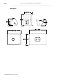
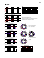
P.30
PS8 & LS400 : SPECIFICATIONS, CURVES & DIAGRAMS
___________________________________________________________________________________________________
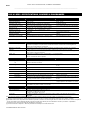
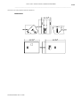
Dimensions
PS SERIES MANUAL REV3 10/10/05
P.31
PS8 & LS400 : SPECIFICATIONS, CURVES & DIAGRAMS
___________________________________________________________________________________________________
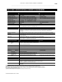
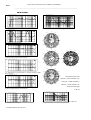
ON AXIS RESPONSE (dB)
TOTAL DISTORTION (%)
10
10%
0
10
1%
20
30
0.1%
30
100
1k
10k
20k
30
On Axis Responses PS8 & PS8 + LS400.
100
1k
10k
PS8+LS400 : THD for 110dBSPL @ 1m.
IMPEDANCE (Ohms)
64
32
All measurements made with PS8TDcontroller.
Response curves : Far Field, Halfspace below 200Hz, anechoic above 200Hz.
Off axis response and polar plot : 1/3 octave averaged anechoic measurements.
Vertical orientations refer to the cabinet in front of house configuration.
Directivity index and factor : computer treatment of polar plots.
16
8
4
30
100
1k
10k
20k
Impedances PS8 & LS400.
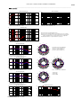
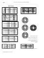
0˚
330˚
OFF AXIS RESPONSE (dB)
30˚
10
300˚
60˚
Horizontal polar plot (left). 5dB/division.
Upper plot : vertical orientation +25˚.
Center plot : vertical orientation 0˚.
Lower plot : vertical orientation -25˚.
0
270˚
90˚
10
240˚
120˚
20
100
1k
10k
20k
210˚
150˚
180˚
Horizontal Plane, Vertical Orientation +25˚.
10˚(black), 20˚(Red), 30˚(Blue) off axis response.
0˚
90˚
330˚
OFF AXIS RESPONSE (dB)
30˚
120˚
60˚
10
300˚
60˚
150˚
30˚
0
270˚
90˚ 180˚
0˚
10
240˚
120˚
210˚
330˚
20
100
1k
10k
20k
210˚
150˚
240˚
300˚
180˚
Horizontal Plane, Vertical Orientation 0˚.
20˚(black), 30˚(Red), 40˚(Blue) off axis response.
270˚
Above : vertical Polar plot. 5dB/division.
0˚
330˚
OFF AXIS RESPONSE (dB)
30˚
10
300˚
60˚
0
270˚
2 500 Hz Red
5 000 Hz Blue
10 000 Hz Black
90˚
10
240˚
120˚
20
100
1k
10k
20k
210˚
150˚
180˚
Horizontal Plane, Vertical Orientation -25˚.
30˚(black), 40˚(Red), 50˚(Blue) off axis response.
DIRECTIVITY INDEX (dB) & Q
COVERAGE ANGLE (Degree)
20
100
15
200˚
100˚
10
10
5
0
100
1k
Directivity Index and Factor.
PS SERIES MANUAL REV3 10/10/05
10k
1
20k
20˚
100
1k
10k
20k
Horizontal (light) and Vertical (black) Coverage Angles, -6dB point.
20k
P.32
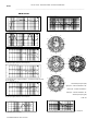
PS10 & LS500 : SPECIFICATIONS, CURVES & DIAGRAMS
___________________________________________________________________________________________________
PS10 & LS500 : SPECIFICATIONS, CURVES & DIAGRAMS
SYSTEM SPECIFICATIONS
PS10 with PS10 TDcontroller
LSub 500 with PS10 TDcontroller
Frequency Response [a]
65 Hz - 20 kHz ±3dB
40 Hz - 110 Hz ±3dB
Usable Range @-6dB [a]
58 Hz - 21 kHz
38Hz - 120 Hz
Sensitivity 1W @ 1m [b]
98 dB SPL Nominal - 96 dB SPL Wideband
101 dB SPL Nominal
Nominal Peak SPL @ 1m [b]
124 to 127 dB Peak (for 200 to 500 W RMS Amp.)
131 to 134 dB Peak (300 to 800 W RMS Amp.)
HF Dispersion [c]
50° to 100° Hor. x 55° Vert. Rotatable Horn, 4 positions
-
Directivity : Q & DI [c]
Q : 16 Nominal
Crossover Frequencies
2 kHz Passive
Nominal Impedance
8 Ohms
4 Ohms
Recommended Amplifiers
200 to 500 Watts into 8 Ohms for 1 x PS10 per channel 400
to 1000 Watts into 4 Ohms for 2 x PS10 per channel
300 to 800 Watts into 4 Ohms
DI : 12 dB Nominal ( f > 3 kHz )
120 Hz Active through PS10 TD
SYSTEM OPERATION
Electronic Controller
The PS10 TDcontroller is precisely matched to the PS10 & LS500 cabinets and includes sophisticated
protection systems. Using PS10 & LS500 without a properly connected PS10 TD will result in poor sound
quality and can damage the components.
Dispersion configuration
After quick-release of the front grille from its fixings, the HF Horn can be rotated in 4 positions for dispersion
configuration.
SubBass
The PS10 can be used without optional LS500 SubBass. Active two-way operation with the LS500 is included
in the PS10 TD. One LS500 matches 2 x PS10, additional LS500 may be used for enhanced effect.
Speaker Cables
PS10 are wired 2- & 2+ on Speakon connectors, LS500 on 1- & 1+. Loop through Speakons are present on
both. Single identical cables can thus be used to loop through combinations of up to 2 x PS10 & 1 x LS500 in
no particular order.
PRODUCT FEATURES
PS10
LSub 500
Components : LF
1 x 10" (25cm) 8 Ohm driver
1 x 15" (38cm) long excursion 4 Ohm driver
1 x 1" throat driver + Low Distorsion,
-
[VLF]
HF
Constant Directivity Asymetrical Dispersion Horn.
Height x Width x Depth
515 x 316 x 277 mm (20.28"x 12.44"x 10.91")
430 x 689 x 528 mm
20.79")
Weight : Net
15 kg (33 Lbs)
33 kg (73 Lbs)
Connectors
2 x NL4MP Speakon 4 pole
2 x NL4MP Speakon 4 pole
Construction
Baltic Birch Ply finished with structured black coating
Baltic Birch Ply & structured black coating
Fittings:
Handles
2 Metal recessed pockets
2 Metal recessed pockets
Front finish
Acoustic foam on hex perforated steel grille (77%
transparent)
Perforated steel grilles
Flying Points
Stand fittings
Fixed Installation
(16.93"x 27.13"x
1 steel anchor plate for flying track on top (6 positions).
3 steel anchor plates for flying
2 steel anchor plates for flying tracks on bottom (1 position)
tracks on sides and back
Built in Steel Stand Fitting, 35mm (1"3/8)
Internal Steel Stand Fitting on Top (35mm,
1"3/8) accepts a mast supporting 1 or 2 PS10's.
Two sets of 4 fixing points (Omnimount 100 Std spacing)
-
for Horizontal or Vertical installation.
Power Supply
110/220 Volts (internal wiring), 50/60Hz.
Dimensions & Weight
1U 19" Rack.
Earth-Lift (back panel)
190mm (7.5") Depth.
2.9 kg (6.6 Lbs) net
SHIPPING & ORDERING
Packaging
Shipping weight & Volume
PS10's are packaged as pairs with PS10TD (Ref: PS10P+T) or without PS10TD (Ref : PS10P) in a single box.
Ref PS10P : 34 Kg (pair). Ref PS10P+T : 37 Kg (pair+processor). Shipping Volume : 0.169 m3 ( 5.96 cu feet)
Ref LS500 : 38 kg (unit) 0.238 m3 (8.41 cu feet)
PS SERIES MANUAL REV3 10/10/05
PS10 & LS500 : SPECIFICATIONS, CURVES & DIAGRAMS
___________________________________________________________________________________________________
Accessories
Flying Kit (Ref: FLYPS10) containing 1 x PS10 Top Rail, 2 x PS10 Bottom Rails, 4 x Single Stud Flying Rings.
Mast Adapter Kit (Ref: STDUPS10) containing 1 m (39") long mast & U coupler supporting 1 or 2 PS10 above
LS500
As part of a policy of continual improvement, NEXO reserves the right to change specifications without notice.
[a] Response curves & data : Anechoïc Far Field for the PS10 + PS10TD. Half-Space Anechoïc radiation for the LS500 + PS10TD.
[b] Sensitivity & Peak SPL data : these will depend on spectral distribution and crest factor of program material. Measured with band limited Pink Noise.
Nominal refers to Voice Decade (300 Hz - 3 kHz), Wideband to the specified ±3dB range. Data are for speaker + processor + recommended amplifier
combinations. Peak SPL is at clipping of recommended amplifier.
[c] Directivity curves & data : obtained by computer treatment on off axis response curves.
Omnimount is a registered trade mark of Omnimount Systems Inc.
Dimensions
PS SERIES MANUAL REV3 10/10/05
P.33
P.34
PS10 & LS500 : SPECIFICATIONS, CURVES & DIAGRAMS
___________________________________________________________________________________________________
PS10 Curves
ON AXIS RESPONSE (dB)
TOTAL DISTORSION (%)
10.000
10
0.0
-10.00
1
-20.00
-30.00
0.1
30
100
1k
10k
20k
c 1 : On axis responses PS10 & PS10 + LS500
30
100
1k
10k
20k
c 2 : PS10 + LS500 : THD for 110 dBSPL @ 1m.
IMPEDANCE (Log Z)
30.000
0°
30°
24.000
18.000
30°
60°
60°
12.000
16037 Hz
10085 Hz
5086 Hz
90°
90°
6.0000
30
100
1k
10k
20k
c 3 : Impedance PS10 and LS500
OFF-AXIS RESPONSE (dB)
120°
10.000
120°
150°
0.0
150°
180°
0°
90°
30°
-10.00
30°
60°
120°
60°
60°
30°
150°
-20.00
100
1k
10k
20k
c 4 : Horizontal plane, vertical orientation +25°.
10°(black),20°(light),30°(dark) off axis response
16037 Hz
10085 Hz
5086 Hz
90°
16037 Hz
10085 Hz
5086 Hz
90° 180°
0°
OFF-AXIS RESPONSE (dB)
10.000
120°
120°
150°
30°
0.0
150°
150°
120°
60°
90°
180°
-10.00
0°
30°
30°
-20.00
100
1k
10k
20k
c 5 : Horizontal plane, vertical orientation 0°. 20°(black),30°(light),40°(dark)
off axis response
60°
60°
16037 Hz
10085 Hz
5086 Hz
OFF-AXIS RESPONSE (dB)
10.000
90°
-Horizontal polar plots (left)
90°
upper plot : vertical orientation +25°
0.0
120°
120°
center plot : vertical orientation 0°
-10.00
150°
150°
lower plot : vertical orientation -25°
180°
-20.00
100
1k
10k
20k
-Vertical polar plot (right)
c 6 : Horizontal plane, vertical orientation -25°.
30°(black),40°(light),50°(dark) off axis response
5 dB / div
COVERAGE ANGLES (ł)
200
DIRECTIVITY INDEX (dB) & Q
20.000
100
100
15.000
10
10.000
5.0000
20
100
1
0.0
100
1k
c7 : Directivity index and factor.
PS SERIES MANUAL REV3 10/10/05
10k
20k
1k
10k
20k
c 8 : Horizontal (light) and vertical (black) coverage angles, -6dB points.
PS10 & LS500 : SPECIFICATIONS, CURVES & DIAGRAMS
___________________________________________________________________________________________________
Connection Diagrams
PS SERIES MANUAL REV3 10/10/05
P.35
P.36
PS15 & LS1200 : SPECIFICATIONS, CURVES & DIAGRAMS
___________________________________________________________________________________________________
PS15 & LS1200 : SPECIFICATIONS, CURVES & DIAGRAMS
SYSTEM SPECIFICATIONS
PS15 with PS15 TDcontroller MK2
LSub 1200 with PS15 TDcontroller MK2
Frequency Response [a]
50 Hz - 18 kHz ±3 dB
30 Hz - 120 Hz ±3 dB
Usable Range @-6 dB [a]
47 Hz - 18 kHz
29 Hz - 130 Hz
Sensitivity 1W @ 1m [b]
102 dB SPL Nominal. 99 dB SPL Wideband
102 dB SPL Nominal
Nominal Peak SPL @ 1m [b]
131 to 134 dB Peak (for 550 to 1200 W RMS Amp.)
133 to 135 dB Peak (800 to 1200 W RMS
Amp.)
HF Dispersion [c]
50° to 100° Hor. x 55° Vert. Rotatable Horn - 4 positions
-
Directivity : Q & DI [c]
Q : 16 Nominal
-
Crossover Frequencies
900 Hz Passive or Active (internally switchable)
80 Hz Active through PS15 TD
Nominal Impedance
Passive : 8 Ohms or Active : LF : 6 Ohms & HF : 8 Ohms
6 Ohms
550 to 1200 Watts into 8 Ohms for 1 x PS15 per channel
800 to 1200 Watts into 8 Ohms
1000 to 1800 Watts into 4 Ohms for 2 x PS15 per channel
-
Recommended Amplifiers
DI : 12 dB Nominal
SYSTEM SPECIFICATIONS
PS15Bass with PS15 TDcontroller
Frequency Response
40 Hz - 300 Hz
Sensitivity 1W @ 1m
102 dB SPL Nominal. 99 dB SPL Wideband
( f > 1.5 kHz )
Nominal Peak SPL @ 1m
131 to 134 dB Peak (for 550 to 1200 W RMS Amp)
Cutoff Frequency
120 Hz Passive - 6dB per Octave - Reactance compensation
Nominal Impedance
8 Ohms
Recommended Amplifiers
550 to 1200 Watts into 8 Ohms for 1 x PS15Bass per channel
1000 to 1800 Watts into 4 Ohms for 1 x PS15Bass + 1 x PS15 or 2 x PS15Bass per channel
SYSTEM OPERATION
Electronic Controller
The PS15 TDcontroller is precisely matched to the PS15 & LS1200 cabinets and includes protections. Using
PS15 & LSub’s without a properly connected PS15 TD will result in poor sound quality and can damage the
components.
Dispersion configuration
After quick-release of the front grille from its fixings, the HF Horn can be rotated in 4 positions for dispersion
configuration.
SubBass
The PS15 can be used without optional Subbass. Active operation of the LS1000 is included in the PS15 TD.
Speaker Cables
PS15 are wired 2- & 2+ on Passive Input Speakons, LS1000 on 1- & 1+. Loop through Speakons are present
on both. Single identical cables can thus be used to loop through combinations of PS15 in passive & LS1000 in
no particular order.
PRODUCT FEATURES
PS15
LSub 1200
Components :LF
1 x 15" (38 cm) 6 Ohms proprietary
1 x 18" (46 cm) long excursion 6 Ohm
proprietary driver
[Sub]
HF
Height x Width x Depth
1 x 2" throat, 3" Titanium diaphragm, driver + Low Distortion,
Constant Directivity Asymmetrical Dispersion Horn.
675 x 434 x 368 mm
(26.57"x 17.08"x 14.48")
515 x 791 x 597 mm
(20.28"x 31.14"x 23.50")
Dimensions of 2 stacked LS1200 = 1 x LS2000
Weight : Net
29 kg (64 Lb.)
45 kg (99 Lb.)
Speakon Connectors
2 x 4 pole (Passive In & Loop Thru) + 1 x 4 Pole (Active In)
2 x 4 pole (In & Loop Thru)
Construction
Baltic Birch Ply finished with structured black coating
Baltic Birch Ply & structured black coating
Fittings:
Handles
2 Metal recessed pockets
2 Metal recessed pockets
Front finish
Acoustic foam on hex perforated steel grille (77%
transparent)
Perforated steel grilles
1 steel anchor plate for flying track on top (9 positions).
3 steel anchor plates for flying tracks on sides
and back
Flying Points
2 steel anchor plates for flying tracks on bottom (3 positions)
Stand fittings
PS SERIES MANUAL REV3 10/10/05
Built in Steel Stand Fitting, 35 mm (1"3/8)
Internal Steel Stand Fitting on Top (35 mm,
1"3/8) accepts a mast supporting 1 or 2 PS15's.
PS15 & LS1200 : SPECIFICATIONS, CURVES & DIAGRAMS
___________________________________________________________________________________________________
Fixed Installation
PRODUCT FEATURES
One set of 4 fixing points (Omnimount 100 Std spacing)
PS15Bass
Components :.
1 x 15" (38 cm) proprietary. Identical to the PS15 LF unit
Height x Width x Depth.
675 x 434 x 457 mm
Weight :
26 kg (57 Lb)
Net
(26.57"x 17.08"x 17.99")
Speakon Connectors
2 x 4 poles (Passive In & Loop Thru) + 1 x 4 pole (Active)
Construction
Baltic Birch Ply finished with structured black coating
Fittings :
Handles
2 Metal Handles
Front Finish
Acoustic foam on Hex perforated steel grille (77%
transparent)
Flying Points
1 steel anchor plate for flying track on bottom (9 positions).
2 steel anchor plates for flying tracks on top (3 positions).
SHIPPING & ORDERING
Packaging
PS15's are sold as pairs with PS15TD
Shipping weight & Volume
PS15 : 32 Kg (70 lb.) 0.2 cum (7 cu feet).
PS15 TD : 3.85 Kg (8.47 lb.) 0.02 cu m (0.6 cu feet)
Ref. LS1200 : 49 kg (108 lb.)0.32 cu m (11 cu feet)
Accessories
Flying Kit (Ref.: FLYPS15) containing 1 x PS15 Top Rail, 2 x PS15 Bottom Rails, 4 x Single Stud Flying Rings.
Mast Adapter Kit (Ref.: STDUPS15) containing 1 m (39") long mast & U coupler supporting 1 or 2 PS15 above
LS1000.
As part of a policy of continual improvement, NEXO reserves the right to change specifications without notice.
[a] Response curves & data : Anechoic Far Field for the PS15 + PS15TD. Half-Space Anechoic radiation for the LS1000 + PS15TD.
[b] Sensitivity & Peak SPL data : these will depend on spectral distribution and crest factor of program material. Measured with band limited Pink Noise.
Nominal refers to Voice Decade (300 Hz - 3 kHz), Wideband to the specified ±3 dB range. Data are for speaker + processor + recommended amplifier
combinations. Peak SPL is at clipping of recommended amplifier. Measurements made with PS15's in passive operation mode.
[c] Directivity curves & data : obtained by computer treatment on off axis response curves.
Omnimount is a registered trade mark of Omnimount Systems Inc.
Dimensions
PS SERIES MANUAL REV3 10/10/05
P.37
P.38
PS15 & LS1200 : SPECIFICATIONS, CURVES & DIAGRAMS
___________________________________________________________________________________________________
PS15 : Curves
ON AXIS RESPONSE (dB)
TOTAL DISTORSION (%)
10.000
10
0.0
-10.00
1
-20.00
-30.00
0.1
30
100
1k
10k
20k
30
c 9 : On axis responses PS15 & PS15 + LS1000
100
1k
10k
20k
c 10 : PS15 + LS1000 : THD for 115 dBSPL @ 1m.
IMPEDANCE
32 Ohm
16 Ohm
0°
30°
30°
8 Ohm
60°
60°
4 Ohm
2 Ohm
30
100
1k
10k
10000 Hz
5000 Hz
2500 Hz
90°
20k
90°
c 11 : Impedance PS15 and LS1000
OFF-AXIS RESPONSE (dB)
10.000
120°
120°
150°
0.0
150°
180°
0°
90°
30°
30°
120°
60°
-10.00
60°
60°
30°
150°
-20.00
100
1k
10k
20k
c 12 : Horizontal plane, vertical orientation +25°. 10°(black),20°(light),
30°(dark) off axis response
10000 Hz
5000 Hz
2500 Hz
90°
90°
10000 Hz
5000 Hz
2500 Hz
180°
0°
OFF-AXIS RESPONSE (dB)
10.000
120°
0.0
120°
150°
150°
150°
30°
120°
60°
90°
180°
0°
30°
-10.00
30°
60°
60°
-20.00
100
1k
10k
20k
c 13 : Horizontal plane, vertical orientation 0°. 20°(black),30°(light),
40°(dark) off axis response
10000 Hz
5000 Hz
2500 Hz
90°
90°
OFF-AXIS RESPONSE (dB)
10.000
-Horizontal polar plots (left)
120°
120°
upper plot : vertical orientation +25°
0.0
150°
150°
180°
center plot : vertical orientation 0°
-10.00
lower plot : vertical orientation -25°
-20.00
100
1k
10k
20k
-Vertical polar plot (right)
c 14 : Horizontal plane, vertical orientation -25°. 30°(black),
40°(light),50°(dark) off axis response
5 dB / div
COVERAGE ANGLES (Degree)
DIRECTIVITY INDEX (dB) & Q
20.000
100
200
15.000
100
10
10.000
5.0000
1
0.0
100
1k
c15 : Directivity index and factor
PS SERIES MANUAL REV3 10/10/05
10k
20k
20
100
1k
10k
20k
c 16 : Horizontal (light) and vertical (black) coverage angles, -6dB points.
PS15 & LS1200 : SPECIFICATIONS, CURVES & DIAGRAMS
___________________________________________________________________________________________________
Connection Diagrams
PS SERIES MANUAL REV3 10/10/05
P.39
P.40
USER NOTES
___________________________________________________________________________________________________
User notes
PS SERIES MANUAL REV3 10/10/05
P.41
IMPORTANT SAFETY INSTRUCTIONS
___________________________________________________________________________________________________
Analogue TDcontroller: Déclaration de conformité
Cet équipement a été testé et répond aux normes internationales et européennes suivantes en ce qui concerne la compatibilité
électromagnétique et la sécurité électrique:
Sécurité électrique (EU) : IEC 60065 (12/2001) Appareils audio, vidéo et appareils électroniques analogues - Exigences de sécurité
Sécurité électrique (US) : UL60065 Seventh Edition, dated June 30, 2003 category AZSQ, E241312.
Sécurité électrique (CAN) : CSA-C22.2 N°60065:03 Edition, dated April 2003 category AZSQ7, E241312
Sécurité électrique : CB test certificate DK-8371 based on IEC60065-2001 7nd ed. with all national deviations.
Radiated Emission (US) : FFC part15 class B
Radiated Emission (CAN) : Cet appareil numérique de Class B satisfait à la norme canadienne ICES-003.
EN55103-1 (1996) Compatibilité électromagnétique - Norme de famille de produits pour les appareils à usage professionnel
Audio Equipment
audio, vidéo, audiovisuels et de commande de lumière pour spectacles - Partie 1: Emissions.
10CE
EN55103-2 (1996) Compatibilité électromagnétique - Norme de famille de produits pour les appareils à usage professionnel audio,
vidéo, audiovisuels et de commande de lumière pour spectacles - Partie 2: Immunité
Note: Les tests CEM ont été effectués avec les câbles recommandé dans ce manuel. L’utilisation de câbles différents peut dégrader les
performances CEM de l’appareil et ne plus garantir que celui ci satisfait toujours aux exigences de la norme.
Inscriptions normalisées pour la norme FCC américaine. Non traduites.
IMPORTANT SAFETY INSTRUCTIONS
Inscriptions normalisées pour la norme UL américaine. Non traduites.
1) Read these instructions.
2) Keep these instructions.
3) Heed all warnings.
4) Follow all instructions.
5) Do not use this apparatus near water.
6) Clean only with dry cloth.
7) Do not block any ventilation openings. Install in accordance with the
manufacturer’s instructions.
8) Do not install near any heat sources such as radiators, heat registers,
stoves, or other apparatus (including amplifiers) that produce heat.
9) Do not defeat the safety purpose of the polarized or grounding-type plug. A
polarized plug has two blades with one wider than the other. A grounding type
plug has two blades and a third grounding prong. The wide blade or the third
prong are provided for your safety. If the provided plug does not fit into your
outlet, consult an electrician for replacement of the obsolete outlet. (US
market)
10) Protect the power cord from being walked on or pinched particularly at
plugs, convenience receptacles, and the point where they exit from the
apparatus.
11) Only use attachments/accessories specified by the manufacturer.
13) Unplug this apparatus during lightning storms or when unused for long
periods of time.
14) Refer all servicing to qualified service personnel. Servicing is required
when the apparatus has been damaged in any way, such as power-supply
cord or plug is damaged, liquid has been spilled or objects have fallen into the
apparatus, the apparatus has been exposed to rain or moisture, does not
operate normally, or has been dropped.
Information about products that generate electrical noise :
NOTE: The United States Federal Communications Commission (in 47 CFR
15.105) has specified that the following notice be brought to the attention of
users of this product:
This equipment has been tested and found to comply with the limits for a
Class B digital device, pursuant to Part 15 of the FCC Rules. These limits are
designed to provide reasonable protection against harmful interference in a
residential installation. This equipment generates, uses and can radiate radio
frequency energy and, if not installed and used in accordance with the
instructions, may cause harmful interference to radio communications.
However, there is no guarantee that interference will not occur in a particular
installation. If this equipment does cause harmful interference to radio or
television reception, which can be determined by turning the equipment off
and on, the user is encouraged to try to correct the interference by one or
more of the following measures:
- Reorient or relocate the receiving antenna.
- Increase the separation between the equipment and receiver.
- Connect the equipment into an outlet on a circuit different from that to which
the receiver is connected.
- Consult the dealer or an experienced radio/TV technician for help.
The user may find the following booklet, prepared by the Federal
Communications Commission, helpful: How to identify and Resolve Radio/TV
Interference Problems. This booklet is available from the U.S. Government
Printing Office, Washington, D.C. 20402, Stock No. 004-000-00345-4. Use of
a shielded cable is required to comply within Class B limits of Part 15 of FCC
Rules. Pursuant to Part 15.21 of the FCC Rules, any changes or
modifications to this equipment not expressly approved by NEXO S.A. may
cause, harmful interference and void the FCC authorization to operate this
equipment.
CAUTION
RISK OF ELECTRIC SHOCK
DO NOT OPEN
The lightning flash with arrowhead
symbol, within an equilateral triangle
is intended to alert the user to the
presence of uninsulated “dangerous
voltage” within the product's
enclosure that may be of sufficient
magnitude to constitute a risk of
electric shock to persons.
WARNING: To reduce the risk of fire or electric shock,
do not expose this apparatus to rain or moisture.
To avoid electrical shock, do not remove covers.
Dangerous voltages exist inside.
Refer all servicing to qualified personnel only.
The exclamation point within an
equilateral triangle is intended to
alert the user to the presence of
important operating and
maintenance (servicing) instructions
in the literature accompanying
the appliance.
ATTENTION ! Cet appareil est considéré de CLASSE 1 et doit être relié à la terre.
Cet appareil doit toujours être relié à la terre par l’intermédiaire de son cordon d’alimentation. Le raccord à la terre est primordial tant pour la
sécurité des personnes que pour un fonctionnement correct de l’appareil. De plus amples informations peuvent être trouvées dans le chapitre:
page 15.
Utilisation et maintenance
PS SERIES MANUAL REV3 10/10/05
P.42
IMPORTANT SAFETY INSTRUCTIONS
___________________________________________________________________________________________________
IMPORTANT SAFETY INSTRUCTIONS....................................................................................................................... 41
INTRODUCTION................................................................................................................................................................ 43
ENCEINTES......................................................................................................................................................................... 44
INSTRUCTIONS GENERALES POUR LA MISE EN SERVICE ....................................................................................................... 44
CONFIGURATION DU PAVILLON A DIRECTIVITE ASYMETRIQUE ........................................................................................... 47
CONFIGURATION ACTIF / PASSIF (PS15 UNIQUEMENT) ...................................................................................................... 48
UTILISATION DU SUBBASSE (OPTIONNEL)............................................................................................................................ 49
ACCESSOIRES ......................................................................................................................................................................... 49
UTILISATION ET MAINTENANCE ............................................................................................................................................ 52
ANALOGUE TDCONTROLLER : CONSEILS DE CONFIGURATION .................................................................... 54
ANALOGUE TDCONTROLLER MANUEL D’EMPLOI.............................................................................................. 57
INFORMATIONS PRELIMINAIRES ........................................................................................................................................... 57
FACE AVANT .......................................................................................................................................................................... 57
FACE ARRIERE ...................................................................................................................................................................... 60
DESCRIPTIF FONCTIONNEL DU TDCONTROLLER ............................................................................................... 62
PARTIE LINEAIRE ................................................................................................................................................................... 62
ASSERVISSEMENT .................................................................................................................................................................. 62
AMPLIFICATEURS ........................................................................................................................................................... 64
PS10AMP & PS8AMP ............................................................................................................................................................ 64
AMPLIFICATEURS INDEPENDANTS ........................................................................................................................................ 66
ANALOGUE TDCONTROLLERS, SPECIFICATIONS................................................................................................ 68
PS8 & LS400 : SPECIFICATIONS, COURBES & DIAGRAMMES............................................................................. 69
PS10 & LS500 : SPECIFICATIONS, COURBES & DIAGRAMMES........................................................................... 72
PS15 & LS1200 : SPECIFICATIONS, COURBES & DIAGRAMS ............................................................................... 76
PS SERIES MANUAL REV3 10/10/05
INTRODUCTION
P.43
___________________________________________________________________________________________________
INTRODUCTION
NEXO vous remercie d’avoir choisi ce matériel. Ce manuel est destiné à vous fournir les informations
nécessaires ou simplement utiles à l’installation et à l’utilisation des enceintes de la gamme PS :
PS8 et son sub-basse optionnel LS400
PS10 et son sub-basse optionnel LS500
PS15, son sub-basse optionnel LS1200 et le PS15Bass
L’enceinte PS15 est utilisable soit en mono-amplification (passif large bande), soit en bi-amplification,
actif 2 voies. Ce mode est disponible en utilisant un NX242 Digital TDcontroller seulement.
Les anciens contrôleurs pour PS10 et PS15 ne sont pas couverts par ce manuel. Pour plus de
renseignements sur ces appareils veuillez contacter votre distributeur NEXO ou consultez notre site web
www.nexo-sa.com
Prenez le temps de lire ce manuel, certaines indications particulières aux enceintes PS
(configuration du pavillon à directivité asymétrique par exemple) vous aideront à exploiter au
mieux votre système.
PS SERIES MANUAL REV3 10/10/05
P.44
ENCEINTES
___________________________________________________________________________________________________
ENCEINTES
Instructions générales pour la mise en service
Avertissement concernant les niveau de pression sonore élevés
L’exposition à des niveaux de pression sonore important peut entraîner une perte d’audition définitive. La
susceptibilité au bruit varie en fonction de chaque individu, mais en règle générale toute personne
exposée à un niveau sonore intense pendant un temps suffisant perdra de l’audition. L’ organisation de
santé américaine (U.S. Government’s Occupational and Health Administration -OSHA) a établi un
rapport entre le niveau de pression sonore et la durée d’exposition.
Heures par jour
Sound Level dBA, Slow Response
8
90
6
92
4
65
3
97
2
100
1½
102
1
105
½
110
¼ ou moins
115
Selon l’OSHA, toute exposition au bruit supérieure à celle indiquée dans le tableau ci dessus peut
entraîner une perte d’audition définitive. Des protections auditives doivent être employées par le
personnel mettant en œuvre les systèmes de sonorisation décrits dans ce manuel si les pressions
sonores auxquelles il est soumis dépasse les valeur indiquées dans le tableau. Par mesure de sécurité il
est recommandé que TOUTES les personnes exposées à un système permettant de dépasser les valeurs
de SPL dangereuses portent un dispositif de protection auditive pendant le fonctionnement du système.
Utilisation du TDcontroller
Les performances, la qualité sonore et la fiabilité des enceintes sont entièrement conditionnées par
l’emploi, selon les modalités indiquées par NEXO, du contrôleur électronique approprié :
PS8 Analogue TDcontroller pour les systèmes PS8 (avec ou sans LS400)
PS10 Analogue TDcontroller pour les systèmes PS10 (avec ou sans LS500)
PS15 Analogue TDcontroller pour les systèmes PS15 (avec ou sans LS1200)
NX242 Digital TDcontroller chargé sur le set-up approprié. (Voir le manuel « NX242 manuel
d’utilisation »)
Les appareils mentionnés ne sont pas interchangeables, chacun étant précisément adapté aux
enceintes pour lequel il est destiné. Exception faite du NX242 qui couvre l’ensemble de la gamme NEXO.
PS SERIES MANUAL REV3 10/10/05
ENCEINTES
P.45
___________________________________________________________________________________________________
Utilisation du PS15Bass
Le PS15Bass est une enceinte passive utilisant exactement le même signal
que celui fourni au PS15. On peut donc le brancher directement en parallèle
avec celui-ci. Le même TDcontroller peut être utilisé pour les deux enceintes
qui seront protégées de même manière. Si vous vous servez du PS15 en
mode actif, il faudra brancher le PS15 en parallèle avec le haut-parleur de
basse (1+/1-). Pour cela, il faudra aussi passer le PS15Bass en position
active (ou employer un adaptateur qui relie 1+/1- du PS15 au 2+/2- du
PS15Bass). Voir aussi le chapitre suivant.
Câblage des enceintes
Le raccordement des enceintes s’effectue par l’intermédiaire de connecteurs de type SPEAKON, modèle
NL4FC (non fournis). Le câblage en est indiqué sur les plaques sérigraphiées situées à l’arrière des
enceintes.
Les 4 broches des 2 embases SPEAKON portant les mentions sérigraphiées « in / out » sont
raccordées en parallèle à l’intérieur de l’enceinte. Chacun des 2 connecteurs peut donc être utilisé
indifféremment, et recevoir simultanément les signaux destinés à alimenter le système principal (PS) et le
système sub-basse (s’il est présent) : un unique câble à 4 conducteurs permet ainsi le raccordement
entre le rack d’amplification et une ou deux enceintes plus un sub-basse.
PS SERIES MANUAL REV3 10/10/05
P.46
ENCEINTES
___________________________________________________________________________________________________
Sur les enceintes PS10, PS8, LS500, LS1200, LS400 et PS15 (lorsque celle-ci est utilisée en passif
mono-amplifiée), le câblage de ces connecteurs est le suivant :
Speakon Connector
Signal
Pin 1+
Ö
SubBass + (optional)
Pin 1-
Ö
SubBass - (optional)
Pin 2+
Ö
Système principal (PS) +
Pin 2-
Ö
Système principal (PS) -
L’utilisation de l’enceinte PS15 en mode actif 2 voies (bi-amplifiée) requiert le raccordement par un
connecteur SPEAKON réservé à cet effet (mention sérigraphiée « 2 WAY ACTIVE »). Le câblage de ce
connecteur est le suivant :
Connecteur SPEAKON
Signal
pin 1+
Ö
Basse PS15 +
pin 1-
Ö
Basse PS15 -
pin 2+
Ö
Aigu PS15 +
pin 2-
Ö
Aigu PS15 -
Le choix du câble à utiliser se résume principalement au choix d’une section adaptée en tenant compte
de l’impédance de la charge et de la longueur de câble. Il s’agit avant tout de limiter la résistance série du
câble dont une valeur trop élevée introduirait des pertes de puissance et des ondulations dans la courbe
de réponse (facteur d'amortissement).
Le tableau ci-dessous indique, pour 3 sections courantes, la longueur maximum pour une valeur de
résistance série du câble inférieure ou égale à 4% de la charge (facteur d’amortissement 25).
Section du câble
Longueur maxi
Impédance 8 Ohms
Impédance 4 Ohms
1,5 mm²
12 m
6m
2,5 mm²
20 m
10 m
4 mm²
32 m
16 m
Précautions à prendre lors d’une mise en service
Lors de la mise en service d’un système comportant des enceintes neuves, il est recommandé de ne pas
l’utiliser immédiatement à pleine puissance. Les haut-parleurs non stabilisés (particulièrement au niveau
des collages) étants plus fragiles. Le risque d’endommagement est plus élevé au cours des premières
heures d’utilisation. Une montée en puissance progressive évitera ce risque.
Dans tous les cas il est conseillé de ne raccorder les enceintes qu’en dernier lieu, après avoir
préalablement vérifié le fonctionnement normal du reste de l’installation et plus particulièrement le
PS SERIES MANUAL REV3 10/10/05
P.47
ENCEINTES
___________________________________________________________________________________________________
câblage du TDcontroller et des amplis. Une bonne pratique consiste à baisser le gain des amplis lors du
raccordement des enceintes, et de monter le gain de chaque canal individuellement en contrôlant
l’allumage de la LED de Sense correspondante sur le TDcontroller. Ceci permettra de détecter un
éventuel défaut des lignes de Sense, y compris une éventuelle inversion de canal (qui rendrait le
système de protection interne du contrôleur inopérant).
Configuration du pavillon à directivité asymétrique
Principe acoustique.
La dispersion asymétrique du pavillon à directivité constante est une caractéristique importante des
enceintes PS. Ce concept n’était jusqu’ici utilisé que pour des applications très restreintes ; PS8, PS10 et
PS15 l’exploitent pleinement dans tous les cas grâce à la possibilité d’orientation par l’utilisateur.
La configuration adaptée du pavillon, pour les deux applications types les plus courantes (« façade/front
of house » et « retour de scène/wedge ») est décrite et expliquée dans les paragraphes qui suivent.
Les quatre orientations possibles du pavillon étant utilisables, d’autres configurations peuvent être utiles
pour des applications spécialisées, clusters complexes, installations conçues en CAO.
Les caractéristiques particulières des pavillons PS10 et PS15 sont illustrées par la figure 1 (représentant
une enceinte PS10 en configuration « façade ») :
Comme le montre la vue de côté, la couverture verticale est plus faible vers le haut (+25°) que vers le
bas (-30°).
Comme le montre la vue de face, la couverture horizontale est étroite vers le haut (50° pour une
orientation verticale de +25°), et large vers le bas (100° pour une orientation verticale de -30°). Entre les
deux, la couverture horizontale varie de façon continue ; elle est de 75° dans l’axe médian (orientation
verticale 0°).
Pour faciliter l’accès au pavillon et permettre à l’utilisateur de vérifier immédiatement son orientation, la
face avant est équipée d’un système de fixation rapide de la grille (il suffit de tirer celle-ci vers l’extérieur).
Pour modifier l’orientation du pavillon, défaire les 4 vis qui le maintiennent à l’aide d’une clé BTR de 4 ou
TORX 25 (dépend du modèle et de l’âge de l’enceinte). L’orientation du pavillon est indiquée par un
autocollant situé sur la face à large dispersion. La position souhaitée (Wedge/Front of house) doit pouvoir
être lue à l’endroit. La flèche indique le côté large dispersion.
Utilisation en configuration « façade »
50˚
+25˚
Bien couvrir un public nécessite une
combinaison conflictuelle d’enceintes à large
dispersion (« courte portée ») pour les
auditeurs les plus proches (au dessous de
l’axe) et à faible dispersion (« longue
portée ») pour les zones éloignées (dans
-30˚
l’axe et au dessus). La couverture horizontale
du pavillon, variant de « courte portée » à
100˚
« longue portée » le long de l’axe vertical,
permet donc de répondre à ce critère avec
un seul et même système. Pour la majorité des applications de type façade, le pavillon devra être utilisé
PS SERIES MANUAL REV3 10/10/05
P.48
ENCEINTES
___________________________________________________________________________________________________
avec le côté large dispersion (flèche de l’autocollant) dirigé vers le bas.
Utilisation en position « retour de scène »
+3
0˚
100˚
-2
5˚
Pour un retour de scène
(« wedge ») la couverture requise
est toujours plus large lorsque
l’artiste est près de l’enceinte (au
dessus de l’axe) que lorsqu’il s’en
éloigne (au dessous de l’axe). En
retour de scène le pavillon doit être
tourné avec son côté « large »
dispersion (flèche de l’autocollant)
vers le haut de l’enceinte en
position retour, comme l’illustre la
figure ci contre.
50˚
Configuration Actif / Passif (PS15 Uniquement)
La commutation du mode passif (configuration usine) au mode actif demande une intervention sur
l’enceinte ainsi que l’utilisation du NX242 Digital TDcontroller .
L’intervention sur l’enceinte est simple : Après avoir retiré la plaque de connexion, déconnecter le
connecteur 6 pôles (emplacement « P »). Le faire tourner de 180° et l’insérer dans l’emplacement « A ».
Refermer la plaque de connexion. Un bouchon obstrue la prise « Active », le retirer. Nous vous
conseillons vivement d’obstruer de même les deux prises « Passives » pour éviter toute erreur de
connexion.
Voir aussi la section concernant le câblage des enceintes (page 45)
PS SERIES MANUAL REV3 10/10/05
ENCEINTES
P.49
___________________________________________________________________________________________________
Utilisation du Subbasse (optionnel)
Recommandations générales
La section sub-basse du TDcontroller est monophonique (une sommation Gauche + Droite est effectuée
en entrée du TDcontroller).Dans le cas d’une installation comportant une section sub-basse en stéréo
(ce qui implique l’utilisation de 2 TDcontrollers), ne pas oublier que le fait de ne raccorder qu’une seule
entrée du Contrôleur entraîne une diminution de gain de 6 dB sur le canal de Sub. Pour s’en affranchir
sans être obligé de corriger la position du potentiomètre de niveau de Sub, il est commode de placer un
« Y » en entrée du Contrôleur. Le TDcontroller permet cette correction en interne . (voir “Affectation des
entrée au canal SUB ” page 61 )
Pour de meilleures performances les sub-basse doivent être le moins éloignés possible des enceintes
principales afin d’éviter les interférences dans la zone de fréquence où ils se recouvrent.
Dans le cas d’une installation comportant plusieurs Sub-basses alimentés par le même signal (mono), il
est généralement préférable de les regrouper. Les rendements nominaux des LS400, LS500 et LS1200,
et les réglages de niveau de Sub prévus sur le Contrôleur qui en tiennent compte, se référent à un
positionnement au sol de ces enceintes. Dans d’autres conditions d’utilisation (sub-basses accrochés en
particulier), le niveau acoustique obtenu sera sensiblement plus faible (de 3 à 6 dB suivant les conditions
particulières d’exploitation) ce qui influera sur le réglage de gain, voire sur le nombre de sub-basses
requis pour équilibrer le niveau de la section Sub en fonction du niveau demandé.
Accessoires
Recommandations de SECURITE propres à tous les accessoires
Inspecter tous les composants avant assemblage. Si vous suspectez un composant ne pas l’utiliser.
Lire attentivement la notice d’assemblage livrée avec l’accessoire.
Un système secondaire d’accrochage doit être installé lorsque l’enceinte est accrochée à sa place de
fonctionnement. Cette sécurité doit répondre aux normes en vigueur de l’endroit où le matériel est utilisé.
Le personnel chargé de suspendre les enceintes doit être équipé de protections personnelles adaptées
(casque, chaussures de sécurité, protection oculaire…)
Ne pas utiliser de personnel non formé pour accrocher des enceintes.
S’assurer que tous le matériel annexe (non fournis par NEXO) (tel que moteurs, élingues, goupilles…)
PS SERIES MANUAL REV3 10/10/05
P.50
ENCEINTES
___________________________________________________________________________________________________
est certifié pour la charge à accrocher et est en état de fonctionnement.
Ne pas autoriser le public ou le personnel à passer sous l’équipement accroché avant la fin de
l’installation.
Ne jamais laisser l’installation sans surveillance tant qu’elle n’est pas terminée.
Eviter, dans la mesure du possible, de suspendre de l’équipement dans des zones au dessus du public.
Pied et mât
Les enceintes PS8, PS10 et PS15 comportent sur leur face inférieure une douille adaptée à recevoir un
tube de diamètre 35 mm. Ceci permet le placement direct des enceintes, soit sur un pied standard, soit
sur un mât à disposer sur le sub-basse (LS400, LS500 et LS1200 comportent sur leur face supérieure
une douille de même type). Le mât, de même qu’un « coupleur en U » permettant d’implanter 2
enceintes côte à côte à l’extrémité du mât , sont disponibles en option. L’utilisation de ce coupleur est
déconseillée avec l’enceinte PS15 pour des raisons de sécurité.
Rails et pions d’accrochage pour PS10 & PS15
PS10 et PS15 sont équipées de points d’ancrage pouvant recevoir en option :
sur le dessus : un rail aviation à 6 positions
(9 positions sur le PS15)
sur le dessous : deux rails circulaires simples
(PS10) ou deux rails aviation à 3 positions
(PS15).
Ces éléments font partie des kits d’accrochage (fournis en
option) qui comprennent également 4 anneaux de levage
à encliquetage rapide s’adaptant sur les rails. La mise en
place nécessite une clé BTR de 5 / TORX30 (pour le
démontage des vis d’origine) et une clé BTR de 4 /TORX
25 pour la fixation des rails.
L’inclinaison verticale de l’enceinte est fonction de la position des anneaux sur le rail supérieur. Il est
impératif pour des raisons de sécurité d’utiliser 2 anneaux par rail reliés à deux élingues indépendantes,
l’un (B) assurant la stabilisation de l’enceinte en rotation et permettant éventuellement de réduire
l’inclinaison donnée par le premier (A). Les inclinaisons verticales obtenues en fonction de la position de
l’anneau directeur (sans tenir compte de la correction apportée par le second) sont les suivantes :
PS SERIES MANUAL REV3 10/10/05
Position
Angles PS10
Angles PS15
1
-17°
-20°
2
-12°
-16°
3
-7°
-12°
4
-2°
- 8°
5
+3°
- 4°
6
+8°
0°
7
inexistant
+4°
8
inexistant
+8°
9
inexistant
+12°
ENCEINTES
P.51
___________________________________________________________________________________________________
Adaptation de système type Omnimount
L’arrière et le dessous du PS10 comportent des ancrages internes munies d’écrous permettant
l’adaptation d’un système de fixation au standard de fixation Omnimount Série 100, par des vis de type
M8. L’usage en est particulièrement pratique lorsque les enceintes sont à implanter contre des parois, en
position horizontale ou verticale. Pour dégager les écrous, il convient de retirer les vis bouchons d’origine
à l’aide d’une clé BTR de 4 / TORX 25. Veuillez noter que l’Omnimount série 100 n’est pas prévue pour
le poids du PS15. Ne pas utiliser cet accessoire avec le PS15 sans un second point d’accrochage de
sécurité.
Accessoires propres au PS8
FS0081-001
Cet accessoire, équipé de 2 inserts M10 se fixe directement sur l’une des
faces de la PS8.Il doit être utilisé avec d’autres accessoires tels que :
Crochet lumière standard
Anneau de levage mâle M10
Pivot DIN (TV spigot)
FS0081-002
Cet accessoire est équipé de 2 écrous soudés M5 et 1 écrou soudé M10. Il
doit être impérativement utilisé avec le FS0081-001.Il permet la fixation de la
PS8 au plafond, au mur ou sur un pied en utilisant le FS008-003.
FS0081-003
Cet adaptateur est utilisé pour monter la PS8 en
position horizontale sur un pied ou un mat standard de diamètre 35 mm en
complément d’autres accessoires ou directement sur l’un des côtés.
SA0081-001
Cet accessoire de sécurité est composé d’une élingue acier gainée plastique de
30 cm utilisée comme point de sécurité secondaire pour maintenir le grille. La fixation de cette élingue est
extrêmement simple: il suffit de la visser sur la grille d’un coté et sur la vis de fixation du pavillon HF de
l’autre. NEXO recommande que cette élingue de sécurité soit toujours utilisée lorsque le PS8 est utilisé
au-dessus du public. La responsabilité de l’utilisation correcte de l’élingue incombe à l’utilisateur.
PS SERIES MANUAL REV3 10/10/05
P.52
ENCEINTES
___________________________________________________________________________________________________
Utilisation et maintenance
Contrôle des fusibles PS10 et PS15
Le paragraphe suivant ne concerne pas l’enceinte PS8, laquelle est équipée d’un fusible re-amorçable
ne nécessitant pas de maintenance
Les fusibles ont pour fonction de protéger les éléments du filtre passif contre un échauffement excessif
dans l’éventualité où l’un des haut-parleurs est débranché ou en circuit ouvert. La rupture du fusible
empêche aussi, dans ce cas, une surcharge de l’amplificateur en lui évitant d’avoir à fournir une intensité
anormalement élevée. Pour maintenir la qualité du signal, ces fusibles ne sont pas placés en série avec
le moteur et donc ils ne le protègent pas.
Dans tous les cas où l’enceinte a pu fonctionner avec un haut-parleur accidentellement débranché et
après une réparation, il faut vérifier l’état des fusibles et procéder à leur remplacement si nécessaire (il
s’agit de fusibles type « Automobile » d’usage très courant).
Attention : la présence d’un fusible endommagé, susceptible d'entraîner une dégradation de la qualité
sonore et de la fiabilité de l’enceinte, ne se traduit pas par la coupure franche du signal vers l’un des
haut-parleurs et n’est donc pas immédiatement détectable.
PS15 : Fusibles de type automobile, valeurs 5A et 10A situés sur le filtre passif et 5x20 Temporisé
(T500mAL250V) sur le circuit ICN (circuit vissé sur le coté de l’enceinte près du pavillon)
PS10 : Fusibles de type automobile, valeurs 3A et 10A situés sur le filtre passif
Pour contrôler les fusibles, défaire les 4 ou 6 vis qui maintiennent la plaque de connexion (clé BTR de 2,5
/ TORX 20) et dégager la plaque en la faisant pivoter. Le circuit ICN (sur le PS15 uniquement) est situé
près du moteur HF et est accessible après démontage du pavillon.
PS SERIES MANUAL REV3 10/10/05
ENCEINTES
P.53
___________________________________________________________________________________________________
Dépannage rapide
En dehors des opérations de maintenance proprement dites, certaines vérifications simples ne
nécessitant pas d’équipement de mesure peuvent être réalisées par un utilisateur suspectant une
anomalie dans le fonctionnement du système. La première question à se poser doit toujours être
l’identification du « maillon » défaillant : source, contrôleur, ampli, enceinte ou câbles ? La réponse est
facilitée lorsqu’on se trouve, comme c’est souvent le cas dans une installation stéréo, dans une situation
où un canal fonctionne apparemment normalement et l’autre pas. La permutation des éléments permet
alors de localiser celui qui est défaillant.
A supposer que le défaut provienne d’une enceinte, certaines « pannes » peuvent être assez facilement
détectées et corrigées par l’utilisateur (à défaut d’appareillage de mesure complexe, l’usage d’un simple
générateur sinusoïdal à balayage facilitera les investigations) :
Vibrations parasites dues à des vis desserrées.
Bruits d’air dus à des fuites : vérifier qu’aucune vis ne manque (vis bouchon en particulier).
Vibration d’une grille de face avant mal repositionnée.
La détection de certaines pannes peut nécessiter le démontage de l’enceinte :
Fusibles (voir paragraphe précédent)
Corps étranger introduit accidentellement dans l’enceinte.
Fils de liaison tapant contre la membrane d’un haut-parleur : vérifier en démontant le haut-parleur (vis
BTR de 4).
Haut-parleur débranché (ou branché hors phase) suite à une précédente intervention.
Maintenance et garantie
Les systèmes NEXO (Enceintes et Electronique) sont garantis pièces et main d’œuvre dans une période
de deux ans à partir de la date d’achat. Le matériel sous garantie pourra être soit réparé soit remplacé.
Le matériel devra être envoyé (envoi pre-payé) dans un emballage adéquat à un centre autorisé pour la
maintenance NEXO. Toute intervention par du personnel non qualifié/non autorisé par NEXO annulera la
garantie. La garantie ne couvre pas la peinture ou la finition. La garantie ne s’applique pas à du matériel
endommagé par un mauvais usage, usage abusif, accidenté ou ayant subi des modifications
PS SERIES MANUAL REV3 10/10/05
P.54
ANALOGUE TDCONTROLLER : CONSEILS DE CONFIGURATION
___________________________________________________________________________________________________
Analogue TDcontroller : Conseils de configuration
Alimentation secteur
AVERTISSEMENT! CET APPAREIL DOIT ÊTRE RELIE A LA TERRE.
Le conducteur vert et jaune du câble secteur doit toujours être connecté à la terre de sécurité ou à la
masse d'une installation. La terre est essentielle pour la sécurité du personnel comme pour l'installation
correcte du système, et elle est connectée de manière interne à toutes les surfaces métalliques
exposées. Toute structure de type rack dans laquelle cet appareil peut être monté est supposé être
connecté au même circuit de terre.
Aucun moyen d'éteindre les TDcontroller NEXO depuis la face avant n'est prévu. Cet équipement étant
prévu pour fonctionner dans un rack la face arrière n’est pas disponible, Il est laissé à l'initiative de
l'utilisateur de prévoir un moyen de déconnexion accessible en permanence.
Détermination de la tension
Les TDcontroller NEXO utilisent une alimentation à découpage (SMPS). Cette SMPS accepte les
tensions de secteur alternatif universelles comprises entre 90V et 264V, et ne nécessite aucune
intervention manuelle pour les tensions comprises dans cette plage.
Montage du TDcontroller dans un rack (mise à la terre, blindage et sécurité)
Le TDcontroller doit être installé dans un rack fermé. La seule partie accessible doit être le panneau de
face avant. Tout les espaces libres au dessus ou au dessous du TDcontroller doivent être obstrué de
manière a empêcher le contact avec le dessus et le dessous du TDcontroller.
Le rack est une structure de mise à la masse et de blindage ouverte, et procure un blindage
supplémentaire. Pour cette raison, il est souhaitable que les vis utilisées pour fixer le TDcontroller dans le
cadre de support ou le rack établissent un contact électrique entre le châssis du TDcontroller et le rack.
La première raison de la mise à la masse est la sécurité. La conformité aux exigences légales en vigueur
est, bien entendu, obligatoire. Cependant, la mise à la masse a aussi un effet sur la compatibilité
électromagnétique. Du point de vue de la CEM, il est souhaitable d'avoir un réseau de masse à faible
impédance, car ainsi un courant passant par le réseau de masse produira une faible tension dans le
réseau. Un réseau à faible impédance peut être obtenu en utilisant un schéma de masse multipoints,
comportant autant de boucles de masse fermées qu'il est économiquement possible.
Fusible
Le fusible se trouvant dans l'appareil ne doit pas brûler en fonctionnement normal. Si le fusible brûle, un
disfonctionnement du NX 242 s'est produit. Ce fusible ne peut être changé que par un personnel de
maintenance certifié par NEXO. En aucun cas, ne remplacez le fusible par un fusible autre que certifié
par NEXO, cela annulerait la garantie.
ATTENTION!
Ces instructions de maintenance sont destinées uniquement au personnel de maintenance qualifié. Afin
d'éviter les risques de choc électrique, n'effectuez aucune opération de maintenance autre que celles
figurant dans les instructions d'utilisation, à moins que vous ne soyez qualifié pour le faire.
PS SERIES MANUAL REV3 10/10/05
ANALOGUE TDCONTROLLER : CONSEILS DE CONFIGURATION
P.55
___________________________________________________________________________________________________
Recommandations concernant le câblage des lignes de Sense
L'impédance d'entrée des entrées Sense du TDcontroller est élevée, le courant qui circule est par
conséquent faible, bien que les tensions soient élevées. Il n'est donc pas indispensable d'employer un
type de câble spécial. Si le TDcontroller est installé dans la baie d'amplification, il est possible de se servir
d'un câble non blindé.
Si le TDcontroller est disposé à distance -à l'emplacement du mixage- un câble blindé est recommandé,
sans utiliser le blindage comme conducteur. Le câble doit être protégé contre l'accès du public, car il
véhicule des tensions d'amplification qui peuvent être dangereuses.
Lorsque l'un des canaux n'est pas utilisé et que la ligne Sense est déconnectée, la diaphonie dans la
ligne Sense peut en certains cas produire une illumination sans objet de la LED sense de ce canal; bien
que cela n'affecte pas le fonctionnement du TDcontroller, ce problème peut être résolu en courtcircuitant les terminaisons de la ligne sense inactive.
Recommandations pour la connexion des sorties audio
Les étages de sortie sont capables de piloter plusieurs amplificateurs en parallèle ; il est toutefois
déconseillé de travailler avec des charges dont l'impédance est inférieure 1kOhms (et il est strictement
interdit d'alimenter des charges inférieures à 600 Ohms. Il est préférable de vérifier les caractéristiques
d'impédance des entrées des amplificateurs fournies par le constructeur afin de s'assurer combien de
canaux d'amplification peuvent être mis en parallèle. S'il est impossible de disposer d'une information
précise (et en prenant 10 kOhms comme valeur minimum possible), un nombre de dix canaux en
parallèle par sortie constitue un maximum réaliste.
Environnement électromagnétique
Les exigences en matière d'émission (ce mot décrit tous types de bruit électromagnétique rayonné par
l'équipement) qui ont été appliquées aux TDcontrollers NEXO sont celles, de la famille de produits
″ Environnement commercial et d'industrie légère ″ suivant le standard CEM pour l'émission.
Les exigences en matière d'immunité (ce mot décrit l'aptitude à supporter les perturbations
électromagnétiques occasionnées par d'autres objets et des phénomènes naturels) que nous avons
retenues dépassent celles qui s'appliquent à la famille de produits ″ Environnement commercial et
d'industrie légère ″ suivant le standard CEM pour l'immunité. Afin de préserver une marge de sécurité,
nous vous recommandons de ne pas utiliser les TDcontrollers en présence d'interférences
électromagnétiques dépassant la moitié de la limite définie dans ce standard.
Ces deux standards CEM sont ceux qui s'appliquent à l'équipement audio-pro pour l'implantation de la
″ directive CEM ″.
PS SERIES MANUAL REV3 10/10/05
P.56
ANALOGUE TDCONTROLLER : CONSEILS DE CONFIGURATION
___________________________________________________________________________________________________
Câbles de signaux analogiques
Low Z
-
+
3
-
2
1
PE
1
+
3
2
PE
SHIELD
1
SHIELD
Les câbles de signaux analogiques doivent
être connectés aux entrées et sorties du
TDcontroller via un câble de type à paire
torsadée et blindée ou starquad, muni de
connecteurs XLR du côté du TDcontroller.
Nous recommandons l'usage de câbles de
basse impédance avec un blindage tressé et
une impédance inférieure à 10 mΩ /m. Pour
les entrées sense, les exigences en matière de
bruit ne sont pas aussi importantes, et toute
sorte de paire torsadée conviendra.
Amplifier
Low Z
Mixing Desk
3
1
2
-
3
+
PE
2
-
Safety
Ground
+
Low Z
Low Z
TDcontroller
IN
OUT
Le TDcontroller doit être utilisé avec des
sources symétriques (par exemple une table
de mixage) et des charges symétriques (par exemple un amplificateur de puissance) (voir la figure).
Vous pouvez voir que le TDcontroller procure une liaison à faible impédance entre la broche 1 de ses
connecteurs XLR et son châssis. Le TDcontroller peut accepter un courant élevé sur la broche 1 sans
dégradation du niveau de bruit de sortie. Nous vous recommandons d'utiliser des sources et des charges
présentant ces mêmes caractéristiques désirables.
On dit parfois que la connexion du blindage aux deux extrémités produit des boucles de masse et que le
courant qui y passe provoque du bruit. Ce n'est pas le cas pour la plupart des équipements audio
professionnels. Brièvement, il y a deux sortes de boucles dans lesquelles des tensions sont présentes:
les boucles constituées par les câbles de signaux, et les boucles constituées par des conducteurs reliés
à la masse, parmi lesquels on trouve les terres de sécurité (PE) et les blindages de câbles de
signaux.Quand un blindage de câble est à la masse à ses deux extrémités, une boucle est fermée, et le
courant qui en résulte occasionne une réduction des tensions induites sur les lignes de signaux. C'est
bien l'effet qu'est censé produire le blindage de câble, puisque c'est ainsi qu'il protège le signal des
champs magnétiques.
Amplifier
Low Z ?
Mixing Desk
0V
Low Z ?
3
2
1
?
1
3
3
+
2
PE
SHIELD
1
-
+
SHIELD
Si vous utilisez une source asymétrique
(déconseillé), le mieux est d'utiliser une paire
torsadée blindée et de connecter le conducteur 3
du câble au blindage à l'extrémité qui se trouve
du côté de la source (voir figure). Cette technique
évite que des courants générateurs de bruit ne
s'écoulent sur le chemin de retour du signal. Si
vous utilisez un amplificateur avec une entrée
asymétrique, le mieux est d'utiliser une paire
torsadée blindée, et de connecter le conducteur
3 uniquement à l'extrémité du TDcontroller,
comme présenté sur la figure ci contre. Ceci
préserve un bon équilibre de la capacité pour le
signal, bien que du courant générateur de bruit
se trouve sur le chemin de retour du signal.
(Notez que ce n'est acceptable que pour un
câble court).
1
2
-
+
3
-
PE
2
Safety
Ground
+
Low Z
Low Z
IN
TDcontroller
OUT
Si vous utilisez une source ou un amplificateur symétrique qu i tend à devenir bruyant lorsqu'un courant
de moins de 100 mA aux fréquences du secteur (50 Hz ou 60 Hz) alimente la broche 1 de ses
connecteurs XLR, alors vous pouvez envisager d'ouvrir les boucles de masse.
PS SERIES MANUAL REV3 10/10/05
ANALOGUE TDCONTROLLER MANUEL D’EMPLOI
P.57
___________________________________________________________________________________________________
Analogue TDcontroller MANUEL D’EMPLOI
Informations préliminaires
Chaque Analogue TDcontroller est destiné à être utilisé avec des enceintes PS et LSub dédiées. Ils ne
sont pas interchangeables. Ses fonctions principales sont :
L’égalisation de la courbe de réponse des enceintes
En cas d’utilisation d’un système Sub-basse (optionnel), le filtrage du signal en 2 bandes de
fréquence (système principal PS et système Sub-basse LSub)
La protection active des enceintes par traitement dynamique du signal Audio (asservissement en
Température et Déplacement)
La réduction de l’écrêtage des amplificateurs (fonction Peak limiter)
L’ Analogue PS TDcontroller c’est aussi :
Fonctionnement stéréo (2 voies indépendantes) pour les canaux du système principal
Niveau de sortie global commutable.
Réglage de niveau du canal Sub-basse par rapport au système principal
Etages d’entrée et de sortie symétriques, haute rejection de mode commun.
Compensation des effets de compression thermiques sur la courbe de réponse du système.
Comme les autres appareils du même type, l’Analogue TDcontroller est destiné à être inséré entre
l’appareil constituant le dernier maillon de la « source » Audio (console, préamplificateur, lecteur C.D., etc.) et
l’amplificateur de puissance.
Face Avant
La majorité des fonctions et indications de la face avant sont réparties à l’intérieur de 2 cadres distincts :
Le cadre gauche concerne les fonctions et indications propres à la section Sub-basse optionnelle, le
cadre de droite (mention supérieure TD) regroupe les témoins des fonctions d’asservissement des
enceintes PS. Pour de plus amples détails sur le fonctionnement de l’asservissement et des autres
PS SERIES MANUAL REV3 10/10/05
P.58
ANALOGUE TDCONTROLLER MANUEL D’EMPLOI
___________________________________________________________________________________________________
traitements électroniques internes, se reporter à “DESCRIPTIF FONCTIONNEL DU TDcontroller” Page
62.
Mise en service du canal LSub Overlap / Crossover
Lorsque l’on actionne le bouton
CONFIGURE le filtre passe haut du PS
est modifié. La sortie sub est, elle,
inchangée. (la sortie sub délivre de
manière permanente un signal destiné
au LS). La position « Overlap » est celle
qui utilise le PS au maximum de sa
bande passante.
La positon « Overlap » doit être utilisée lorsque l’on utilise le système sans LS. Si l’on utilise le système
avec son Subbass associé la positon « Overlap » produira un accroissement de niveau à la fréquence
de coupure. Pour obtenir une réponse plate utiliser la position « Crossover ».
Réglage de niveau du LSub (Sub Level)
Le potentiomètre règle le niveau du canal Subbasse, sur une course de 12 dB, permettant de
l’adapter aux différentes configurations et
conditions d’utilisation. La position centrale du
potentiomètre est adaptée à la configuration 1
LSub pour une paire de PS écartées.
Contrôles d’amplificateur (Sense & Pk)
La diode bicolore vert/rouge AMP indique la
présence de signal sur l’entrée Sense du canal
correspondant, permettant une vérification visuelle
de la liaison entre la sortie d’amplificateur de ce
canal et le contrôleur. La diode flash en rouge,
indiquant l’action du Peak limiter réduisant les
niveaux de tension crête trop élevés ou
susceptibles de surcharger l’amplificateur du canal
correspondant.
L’allumage de la LED jaune VLF indique le déclenchement de protections en déplacement concernant
l’enceinte LSub de la voie Sub-basse. Seule la protection en déplacement est indiquée.
Dans chacune des 2 moitiés du cadre concernant le système principal, les LEDs jaune TEMP et DISP
indiquent le déclenchement du système de protection interne (en température ou en déplacement)
concernant le haut-parleur Grave (les protections agissant sur les Aigus ne sont pas indiquées) de
l’enceinte PS du canal Gauche ou Droite.
PS SERIES MANUAL REV3 10/10/05
ANALOGUE TDCONTROLLER MANUEL D’EMPLOI
P.59
___________________________________________________________________________________________________
Réglage des peak limiters
L’ « Analogue TDcontroller » possède trois réglages de « peak limiter » indépendants vous permettant
de régler le seuil des « peak limiters »en fonction de la puissance de votre amplificateur. Ce réglage
n’affecte pas les seuils des protections. Ce réglage n’a pas fonction de protection à proprement parler. Il
évite la surcharge de l’amplificateur. (Son désagréable du clip et génération de très basses fréquences
par la modulation des rails d’alimentation de l’amplificateur).
Pour régler le « peak limiter » à une valeur correcte vous pouvez soit tourner le potentiomètre en face de
l’indication de puissance (sous 8 ohms) correspondant à votre amplificateur, soit visuellement faire
correspondre l’allumage de la diode de clip du processeur (rouge) à l’allumage de la diode de clip de
l’amplificateur
PS SERIES MANUAL REV3 10/10/05
P.60
ANALOGUE TDCONTROLLER MANUEL D’EMPLOI
___________________________________________________________________________________________________
Face Arrière
LEFT
RIGHT
0dB
OUPUT
LEVEL
-6dB
BALANCED INPUTS
Audio Inputs
RIGHT
SUB L+R
BALANCED OUTPUTS
LEFT
+6dB
Commutateur du niveau de sortie
+ LEFT -
EARTH
LIFT
+ SUB -
+ RIGHT -
(from amp terminals)
Les sorties Audio sont les 3 connecteurs XLR 3 mâles insérés dans la section portant la
mention BALANCED OUTPUTS. Le canal correspondant à chaque connecteur de sortie est
identifié par les mentions Left (canal Gauche), Right (canal Droit), et Sub L+R (canal Subbasse mono). Les broches actives des XLR de sortie sont les broches 2 et 3, la broche 1 étant
reliée à la masse électrique.
En cas de raccordement avec un amplificateur à entrées symétriques, le branchement sur les
XLR de sortie s’effectue par simple liaison broche à broche (1 à 1, etc.), la polarité du signal
étant alors respectée si l’appareil connecté en entrée est lui-même symétrique (voir
paragraphe précédent). (voir aussi page « Recommandations pour la connexion des sorties
audio » page 55 pour le raccordement d’appareil non symétriques)
CAUTION !
To reduce the risk of electric schock
grounding of the center pin
of this plug must be maintained.
Les entrées Sense des 3 canaux (Gauche, Droite et Sub-basse) sont regroupées sur une
barrette de connexion à 6 pôles encastrée dans la face arrière à l’intérieur du cadre portant la
mention Sense INPUT. Les entrées Sense sont destinées à recevoir le signal de sortie des
amplificateurs alimentant une enceinte de chacun des canaux en service : PS pour les canaux
Gauche et Droite, LSub pour le canal Sub-basse.
03105
4004
Sorties Audio
s.n:
PS8 TDcontroller
MADE IN FRANCE
Le commutateur à 3 positions permet simplement d’adapter les niveaux de sortie en fonction
du gain des amplificateurs afin de conserver un rapport signal/bruit optimum (l’adaptation de
niveau étant réalisée en sortie), et ceci quel que soit le gain de l’amplificateur. Les valeurs de
gain possibles sont -6dB 0 +6dB. Pour des conditions de bruit optimales on choisira le réglage
–6dB, pour une réserve importante avant écrêtage on préférera le réglage +6dB.
Entrées Sense
10CE
SENSE INPUT
CAUTION !
Sense line must be connected
for speaker protection.
50 - 60Hz 10W
115 - 230V
Les entrées Audio sont les 2 connecteurs XLR 3 femelles insérés dans le cadre portant la
mention BALANCED INPUTS, les mentions Left et Right identifiant respectivement les
canaux Gauche et Droite. Les broches actives des XLR sont les broches 2 et 3, la broche 1
étant reliée à la masse électrique. En cas de raccordement avec un appareil à sorties
symétriques, le branchement sur les XLR d’entrée s’effectuera par simple liaison broche à
broche (1 à 1, etc.). En raison du caractère symétrique des sorties du PS TDcontroller (et
sous réserve que cette symétrie soit respectée dans la liaison avec l’amplificateur), il n’y a pas
de point chaud et de point froid, le PS TDcontroller étant neutre pour la polarité du signal.
(voir aussi « Câbles de signaux analogiques » page 56)
PS SERIES MANUAL REV3 10/10/05
P.61
ANALOGUE TDCONTROLLER MANUEL D’EMPLOI
___________________________________________________________________________________________________
Le raccordement s’effectue sur la partie femelle - débrochable - du connecteur (fournie par NEXO)
comme indiqué ci-dessous :
Channel
PS Left
PS Right
LS
Amplifier Output Terminal
Barrier strip connector
- (black)
Ö
pin 1 (figure)
+ (red)
Ö
pin 2
- (black)
Ö
pin 3
+ (red)
Ö
pin 4
- (black)
Ö
pin 5
+ (red)
Ö
pin 6
Le branchement des lignes Sense est OBLIGATOIRE pour garantir la sécurité du système. Si les
Senses ne sont pas connectées, le système ne sera pas protégé.
Earth Lift
Le bouton poussoir portant la mention Earth Lift permet
de raccorder (position poussé), ou de déconnecter
(position relâché) la masse électrique de l’appareil avec
la Terre, elle-même reliée par construction au châssis.
L’utilisation de ce bouton correctement positionné permet
dans certains cas (mauvais raccordement des masses) d’éliminer les bruits de ronflements.
Affectation des entrée au canal SUB (sommation mono)
Dans certaines applications, on souhaite désactiver la sommation mono (tout en gardant l’accroissement
de gain de +6dB). En déplaçant le cavalier ST1 –nécessite l’ouverture de l’appareil- le canal SUB
utilisera seulement le signal de l’entrée Right (Droite).
Veuillez vous assurer, avant toute intervention que l’appareil est déconnecté du secteur. Enlevez ensuite
les trois vis maintenant le capot supérieur. Le cavalier ST1 est situé à coté des XLR d’entrées (voir
photo). La broche 1 est la broche la plus proche des prises. Liez les broches 1-2 (position B du dessin)
pour que le SUB n’utilise que l’entrée droite. Liez 2-3 (A dans le dessin) pour revenir à la configuration
d’usine sommation droite-gauche.
1
2
3
A
PS SERIES MANUAL REV3 10/10/05
B
P.62
DESCRIPTIF FONCTIONNEL DU TDCONTROLLER
___________________________________________________________________________________________________
DESCRIPTIF FONCTIONNEL DU TDcontroller
Partie linéaire
Il s’agit des fonctions de traitement électronique dont l’effet sur le signal est indépendant du niveau, par
opposition aux fonctions d’asservissement décrites plus loin.
Filtrage des très basses et très hautes fréquences
Un filtre passe-haut et un filtre passe-bas limitent la bande passante du signal à la bande utile, en
éliminant les composantes très basses et très hautes fréquences susceptibles de dégrader le
fonctionnement du contrôleur ou des amplificateurs. Ces filtres sont optimisés pour participer également
à l’égalisation globale de la courbe de réponse.
Egalisation des enceintes
La section égalisation opère une correction de la courbe de réponse du système. Cette correction est en
effet nécessaire car les enceintes ne sont pas conçues pour avoir une réponse acoustique plate, mais
plutôt un rendement acoustique maximum sur toute la bande de fréquences. Le fait d’atténuer
électroniquement et non passivement les zones de rendement excessif permet de soulager
l’amplificateur et donc d’augmenter le niveau SPL pouvant être atteint pour un amplificateur de puissance
donnée.
L’égalisation a aussi pour fonction d’étendre la bande passante du système, notamment aux basses
fréquences où le rendement acoustique est limité par le volume de l’enceinte.
Filtrage de séparation PS/ LSub
Les signaux d’entrée sont additionnés pour produire un signal mono filtré ensuite en passe-bas pour
alimenter le canal Sub-basse. Dans la positon CROSSOVER (Bouton enfoncé), les filtres passe-haut
des canaux principaux (Gauche et Droite) sont reconfigurés pour éliminer les bandes de fréquence
inférieures à la fréquence de coupure. Les pentes et les caractéristiques de ces filtres sont optimisés par
ordinateur en tenant compte des réponses acoustiques spécifiques des haut-parleurs de l’enceinte.
Asservissement
L’asservissement du PS TDcontroller est normalement destiné à fonctionner en présence de signal sur
les entrées Sense (visualisé par les LEDs de face avant).
VCAs et VCEQs
Sur chacun des 3 canaux Audio (Gauche, Droite et Sub-basse) sont insérés 2 éléments dont l’action est
soumise à une tension de commande contrôlée par la section d’asservissement :
Un des éléments agit sur l’ensemble de la gamme de fréquences (VCA large bande).
L’autre a une action sélective en fréquence comparable à celle d’un égaliseur dynamique (VCEQ Grave).
Suivant la nature et l’origine du signal d’asservissement, l’un ou l’autre ou une combinaison de ces 2
PS SERIES MANUAL REV3 10/10/05
DESCRIPTIF FONCTIONNEL DU TDCONTROLLER
P.63
___________________________________________________________________________________________________
éléments sont utilisées pour traiter le signal Audio, ceci permettant d’augmenter l’efficacité du traitement
et d’en réduire les effets audibles indésirables.
Asservissement en Déplacement.
Le signal de l’entrée Sense est transmis à un filtre conformateur puis redressé pour produire une tension
électrique proportionnelle au déplacement de la bobine mobile. Lorsque la valeur de cette tension atteint
un seuil pré-réglé, le VCEQ Grave est activé (constante d’attaque très courte) pour limiter le
déplacement.
Asservissement en Température.
Le signal de l’entrée Sense est transmis à un filtre conformateur produisant un signal proportionnel au
courant instantané traversant la bobine du haut-parleur. Ce signal est redressé puis intégré avec des
constantes de temps d’attaque et de relâchement analogues aux constantes de temps thermiques
spécifiques du haut-parleur concerné, simulant ainsi son échauffement. Lorsque la valeur de cette
tension atteint un seuil pré-réglé le VCA est contrôlé pour limiter la température en deçà de la valeur maxi
admise.
Contrôle Dynamique
Pour éviter les effets indésirables induits par la constante de temps d’attaque normalement très longue
du signal de détection en température, une double détection est réalisée, la deuxième avec une
constante de temps nettement plus courte en relation avec le niveau sonore subjectivement perçu. Tout
en anticipant sur le déclenchement de la protection en température, ce signal de détection permet
d’améliorer le contrôle de la dynamique.
Peak Limiter
Les dispositifs précédemment décrits assurent une protection efficace contre les risques d’échauffement
ou de déplacement excessif des bobines des haut-parleurs. Néanmoins l’application de tensions de
valeur crête très élevées (cas d’amplificateurs très puissants) de même que la déformation du signal due
à une surmodulation excessive représentent un danger potentiel pour les enceintes. De fait le Peak
limiter répond à une double fonction :
Maintien de la qualité sonore à fort niveau (réduction de la distorsion générée par les amplificateurs).
Accroissement de la fiabilité du système de protection (limitation des niveaux de tension absolue à une
valeur acceptable en permanence par l’enceinte, réduction des risques de génération de composantes
très basses fréquences en sortie d’ampli).
PS SERIES MANUAL REV3 10/10/05
P.64
AMPLIFICATEURS
___________________________________________________________________________________________________
AMPLIFICATEURS
PS10Amp & PS8Amp
Les PS8Amp et PS10Amp sont des amplificateurs dédiés aux systèmes PS8 et PS10 et à leurs
subbasses respectifs LS400 & LS500. Identiques quant à leur structure ils partagent les spécifications
suivantes :
Intégration totale d’un TDcontroller (avec connexion de Sense interne) dont les fonctions sont identiques
à celle du TDcontroller indépendant décrit dans le paragraphe « DESCRIPTIF FONCTIONNEL DU
TDcontroller" page 62.
Etage d’amplification commutable instantanément, permettant une utilisation avec subbasse (3 voies
d’amplification) ou en large bande (2 voies d’amplification), optimisant ainsi la puissance disponible en
fonction de la configuration souhaitée. Le câblage de chaque enceinte est réassigné automatiquement.
Tous les connecteurs et réglages sont accessibles de la face avant rendant ainsi leur intégration en
installation fixe ou dans des racks aisée.
Ventilation silencieuse à vitesse variable.
3 Unités de haut.
Inputs
Chaque entrée ligne symétrique est doublée d'un connecteur mâle de
chaînage pour l'utilisation en multiples de PSAmp.Un commutateur L&R
link facilite le câblage en Mono si des PSAmp indépendants sont utilisés
pour les canaux droite et gauche.
PS SERIES MANUAL REV3 10/10/05
AMPLIFICATEURS
P.65
___________________________________________________________________________________________________
Ouputs
Les deux connecteurs Speakon sont configurés automatiquement avec indication visuelle du câblage. La
commutation peut s'effectuer pendant l'emploi avec les enceintes en service.
Sub On = 3 canaux d'amplification :
Les deux canaux PS Stéréo sont assignés aux pôles 2+ et 2- des
deux Speakons. Un seul indicateur lumineux PS est allumé sur
chaque canal Stéréo. Le canal LSub en sommation Mono est assigné
en parallèle aux pôles 1+ et 1- des deux Speakons. L'indicateur LS est
allumé.
Sub Off = 2 canaux d'amplification :
Les deux canaux PS Stéréo sont assignés aux pôles 2+ et 2- des
deux Speakons. Deux indicateurs PS sont allumés sur chaque canal. Les pôles 1+ et 1-des Speakons
sont déconnectés. L'indicateur LS est éteint.
Mise en service du canal Sub
Le commutateur LSub On reconfigure l'amplificateur automatiquement selon ses deux modes de
fonctionnement.
Sub On = 3 canaux d'amplification :
2 canaux de 430 Watts dans 8 Ohms alimentent deux PS en Stéréo.
1 canal de 850 Watts dans 4 Ohms alimente le LSub en sommation Mono.
Sub Off = 2 canaux d'amplification :
2 canaux de 850 Watts dans 4 Ohms alimentent deux ou quatre PS en Stéréo.
Que l'on utilise ou pas le Subbass, l'intégralité de la puissance de l'amplificateur est toujours disponible.
S'il n'est pas exploité, l'amplificateur de Subbass est réaffecté aux PS lors de la configuration. Dans les
deux cas, l'installation reste stéréophonique
Réglage des niveaux
Le potentiomètre cranté Level agit simultanément sur le niveau des 2 ou 3
canaux selon la configuration.
Le potentiomètre cranté LSub Level règle le niveau relatif du LSub par rapport
aux PS lorsqu'il est en fonction. Ce réglage est indépendant du réglage de niveau
général.
Fusibles et secteur
Les fusibles principaux, la sélection du voltage secteur 115/230V et la configuration de mise à la masse
(ground) s'effectuent sous la trappe de sécurité en face avant (en bas à droite).
PS SERIES MANUAL REV3 10/10/05
P.66
AMPLIFICATEURS
___________________________________________________________________________________________________
Le commutateur « ground on/off » peut être actionné à travers deux trous de la trappe sans avoir à la
démonter. Le trou du haut actionne le « ground on » celui de bas le « ground off ».
Le changement de la configuration de secteur ainsi que l’accès aux fusibles s’effectue après avoir retiré
la trappe de sécurité (2 vis extérieures). La configuration du secteur se fait en poussant le commutateur,
à travers deux trous, selon l’indication de la sérigraphie. Les fusibles restent les même quelle que soit la
configuration.
Dans l’éventualité d’une défaillance d’un fusible, les deux fusibles doivent être changés. Il s’agit de
fusibles temporisés 5x20mm de référence T6.3AH250.
Note: Deux autres fusibles sont situés à l’intérieur de l’amplificateur. Ces fusibles ne doivent jamais être
changés par l’utilisateur, leur défaillance est le symptôme d’une panne plus grave dans l’amplificateur.
Dans ce cas contacter un revendeur NEXO.
Le câble secteur peut se situer au choix en face avant ou face arrière (le changement doit être effectué
par un revendeur agrée). Aucun autre contrôle ou connexion n’existe à l'arrière du PSAmp. A la mise en
service, il faut simplement s'assurer de la présence d'une entrée d'air suffisante pour la ventilation.
Amplificateurs independants
Puissance
NEXO recommande d’utiliser systématiquement des amplificateurs de grande puissance. Les
contraintes budgétaires constituent la seule raison qui conduit à choisir des amplificateurs de plus
faible puissance. S’il se produit un incident sur une installation sans protection, le fait d’utiliser des
amplificateurs qui ne délivrent que la moitié de leur puissance nominale (–3 dB) ne changera rien
en ce qui concerne des dégâts possibles. Cela vient du fait que la gestion de la puissance RMS
(efficace) de la composante la plus faible du système est toujours inférieure de 6 à 10 dB aux
caractéristiques des amplificateurs.
Capacité en Courant
Il est particulièrement important que l’amplificateur se comporte correctement lorsque les charges
sont faibles. Un système à haut-parleur est par essence même réactif ; sur des signaux transitoires
comme la musique, il aura besoin d’une intensité instantanée bien plus élevée que son impédance
nominale le laisse supposer (de quatre à dix fois plus). Les spécifications des amplificateurs
donnent toujours une puissance continue RMS (efficace) dissipée dans des charges résistives (ce
qui est absurde) ; la seule information utile dans cette optique est la caractéristique correspondant
à une charge sous 2 . Outre les spécifications constructeur, il est possible de procéder à un test
d’écoute d’un amplificateur en le chargeant avec deux fois plus d’enceintes que ne l’exige
l’application (2 haut-parleurs par canal au lieu d’un, 4 au lieu de 2…) et en le modulant à niveau
élevé (début de l’écrêtage). Si le signal ne se dégrade pas sensiblement, l’amplificateur convient
bien (un échauffement au bout d’environ dix minutes est normal mais la protection thermique ne
doit pas intervenir trop rapidement après le début de l’essai).
Gains de l’amplificateur
Il est très important de connaître le gain en tension de tous les amplificateurs présents dans votre
configuration. La connaissance du gain des amplis est essentielle pour maintenir la cohérence
d’un système et obligatoire dans le cas ou un seul TDcontroller pilote plusieurs amplificateurs. La
tolérance sera de l’ordre de ±0,5 dB. Dans la pratique, cela peut poser des problèmes :
Certains constructeurs d’amplificateurs présentent une sensibilité d’entrée identique pour des modèles
ayant des puissances nominales différentes (cela implique un GAIN DIFFÉRENT pour chaque modèle).
PS SERIES MANUAL REV3 10/10/05
P.67
AMPLIFICATEURS
___________________________________________________________________________________________________
Cette pratique problématique, héritée des applications non professionnelles, est facilement détectable
lorsque le constructeur spécifie la même sensibilité d’entrée pour toute sa gamme de produits (du style
775mV / 0dBm ou 1,55 V / +6dBm). Cela se traduit par des valeurs de gain très élevées sur les modèles
de puissances les plus élevées.
D’autres marques mentionnent un gain constant mais seulement pour une gamme de produits donnée.
Même dans le cas où un constructeur serait conscient de ce problème et applique la règle du gain
constant à tous ses modèles, la valeur qu’il choisit n’est pas nécessairement celle qu’ont retenue d’autres
constructeurs.
Certains constructeurs peuvent fournir des produits dont les tolérances de fabrication sur le même
modèle peuvent atteindre ±1 dB voire plus. Pire encore, il peut accepter de modifier ce gain à la
demande du client sans que cela soit indiqué de façon claire et visible sur l’amplificateur. Certains
amplificateurs disposent de commutateurs de gain internes et il est parfois impossible de connaître le
gain de l’amplificateur sans effectuer de mesures ou sans l’ouvrir.
Au cas où vous ne connaîtriez pas le gain de votre amplificateur (ou si vous souhaitez le vérifier)
veuillez exécuter les instructions suivantes :
1. Débranchez toutes les enceintes reliées à l’amplificateur.
2. À l’aide d’un générateur de signaux, envoyez un signal sinusoïdal (fréquence dans la gamme
audio, 1000 Hz par exemple). Son amplitude Vin est sans importance (1 V est pratique !). Il est
évident que si vous utilisez une sensibilité de 0,7 V, vous saturerez l’entrée de l’amplificateur !
3. Mesurez la tension en sortie de l’amplificateur. Gain = 20 * LOG10 (Vout / Vin)
Quelques exemples :
Gain
20dB
26dB
32dB
Vin
37dB (1.4V sensitivity
/ 1350Wrms)
0.1V
1V
2V
4V
7.1V
0.5V
5V
10V
20V
35.4V
1V
10V
20V
40V
70.8V
N’oubliez pas que des paramètres de sensibilité constants vous donneront des valeurs de gain
différentes pour une puissance de l’amplificateur différente.
Valeur du gain
D’une façon générale, NEXO préconise l’emploi d’amplificateurs à faible gain, 26 dB étant la valeur
recommandée car relativement courante. L’emploi d’amplificateurs à gain élevé représente en effet
un contresens technique en terme de rapport signal / bruit : le bruit en entrée se trouve augmenté
alors que le niveau de tension maximum atteint est le même (4.5 Volts crête à l’entrée suffisent
pour atteindre l’écrêtage d’un ampli de 500 Watts sous 8 Ohm à gain de 26 dB).
Protections avancées
Certains amplificateurs peuvent disposer de certaines fonctions de pointe telles que celles que l’on
rencontre dans les TDcontroller NEXO(« intégration du décalage du haut-parleur », « limiteur »,
« compresseur »...). Ces fonctions ne conviennent pas bien aux besoins spécifiques d’un système et
peuvent interférer avec la protection existante du TDcontroller. NEXO ne conseille pas l’emploi de ces
fonctions.
PS SERIES MANUAL REV3 10/10/05
P.68
ANALOGUE TDCONTROLLERS, SPÉCIFICATIONS
___________________________________________________________________________________________________
Analogue TDcontrollers, Spécifications
Description des fonctions
Entrées Audio
Différentielles, non flottantes, 50 kOhm. Deux connecteurs Neutrik XLR-3F.
Entrée Senses
3 entrées différentielles (PS L&R, LS). 400 kOhm. Connecteur enfichable 6 Poles.
Sorties Audio
Deux sorties G&D PS Audio. Symétriques, non flottantes, 51 Ohm. Deux XLR-3M.
Une sortie Mono (L+R) LS. Symétrique, non flottante, 51 Ohm. Une XLR-3M.
Contrôles
Commutateur de gain (face arrière), 3 positions : -6 / 0 /+6dB.
Réglage “Peak Limiter” PS8 & PS10 (600W-200W/8 Ohms) PS15 (500W-1200W/8 Ohms)
Bouton poussoir “Sub Overlap / Crossover” & Contrôle du gain Sub (-/+ 6dB).
Indicateurs
Diodes Jaunes “LF speakers Protect” (Temp. & Deplac.), Power ON (vert), Diode “Amp Sense &
Peak” (vert/rouge)
Dimensions
1U 19" Rack.
Poids
2.9 kg net
Profondeur 165mm
SPECIFICATIONS
Etages de sortie
+22 /+16/+10 dBm typ. dans charge 600 Ohm pour gain face arrière +6/0/-6dB.
Etages d’entrée
Signal d’entrée maximum : 22dBu. CMRR 90dB @ 1kHz typ.
THD+N
0.05% @ 1kHz Typ. Pour sortie +10dBm
Bruit de fond
PS8TD -100 dBV PS10TD: -103dBV PS15dB: -98dBV pour un gain de 0dB (22 Hz - 22 kHz,
Dynamique
111 dB non pondéré (THD+N à -60dBr sine wave @1kHz + sortie max.)
Diaphonie
104dB
non pondéré)
Filtrage & EQ.
G&D: 12dB/oct filtre passe bas, 12dB/oct filtre passe haut (“crossover” ou ”overlap”), 4 EQs
Paramétrique. Réglages d’usines.
Protections
VCA temp. (SUB,LF & LF), VCEQ deplac. (SUB & LF), Peak Limiter (G/D/SUB), régulation
compression thermique
Alimentation
100-250 Volts (plage continue), 50/60Hz. Puissance 9W. courant d’appel 0.5A. Earth-Lift.
Normes
Marquage CE : réponds aux exigences de sécurité des directives 73/23/EEC & 89/336/EEC
(sécurité : EN60065-12/2001, CEIM: EN55103-1996). Marquage OC DK-8371, cULus 60065
AZSQ E241312, FCC part15 class B
SYSTEM OPERATION
Application
Chaque Analogue TDcontroller est destiné à être utilisé avec des enceintes PS et LSub dédiées.
Ils ne sont pas interchangeables. Une mauvaise utilisation de l’Analogue TDcontroller peut
entraîner un endommagement du système de sonorisation.
SubBass
PS SERIES MANUAL REV3 10/10/05
Le filtrage Actif 2 voies requis pour le LS est intégré au PSTD.
PS8 & LS400 : SPECIFICATIONS, COURBES & DIAGRAMMES
___________________________________________________________________________________________________
PS8 & LS400 : SPECIFICATIONS, COURBES & DIAGRAMMES
SPECIFICATIONS SYSTEME
PS8 avec PS8 TDcontroller
LSub 400 avec PS8 TDcontroller
Réponse en Fréquence [a]
69 Hz - 19 kHz ±3dB
43 Hz – 120 Hz ±3dB
Bande Utile @-6dB [a]
62 Hz - 20 kHz
40 Hz – 140 Hz
Sensibilité 1W @ 1m [b]
96 dB SPL Nominal - 94 dB SPL en Large Bande
99 dB SPL Nominal
SPL Crête Nominal @ 1m [b]
122 à 125 dB Crête (Amplificateur 200 à 500 W RMS)
128 à 131 dB Crête (Ampli 300 à 700 W RMS)
Dispersion HF [c]
50° à 100° Hor. X 55° Vert. Pavillon rotatif, 4 positions
-
Directivité : Q & D.I. [c]
Q : 10 Nominal
Fréquences de Coupure
2.5 kHz Passif
Impédance Nominale
8 Ohms
6 Ohms
Amplificateurs recommandés
200 à 500 Watts dans 8 Ohms pour 1 x PS8 par canal
300 à 700 Watts dans 4 Ohms
D.I. : 10 dB Nominal (f > 1.8 kHz)
120 Hz Actif par le PS8TD
400 à 1000 Watts dans 4 Ohms pour 2 x PS8 par canal
UTILISATION SYSTEME
Contrôleur Electronique
Le PS8 TDcontroller est précisément adapté aux PS8 & LS400 et incorpore des systèmes de protection
sophistiqués. L'emploi de PS8 & LS400 sans PS8TD correctement raccordé dégradera le signal et pourra
endommager les composants. Les PS8 & LS400 peuvent aussi être employés avec le NX242 Digital
TDcontroller
Dispersion Configurable
Après retrait de la grille de sa fixation rapide, la dispersion du Pavillon peut être configurée sur 4 positions.
Subbasse
Le PS8 s'utilise avec ou sans Sub optionnel LS400. Le filtrage Actif 2 voies requis pour le LS400 est intégré au
PS8TD. Un LS400 suffit pour 2 x PS8, un nombre supérieur de LS400 peut être employé pour un renfort de
grave plus important.
Câbles H.P.
Les Speakons sont câblés en 2- & 2+ pour les PS8, 1- & 1+ pour les LS400.
Chaque enceinte a 2 connecteurs. Des câbles uniques identiques peuvent donc alimenter en série
jusqu’à 2 x PS8 & 1 x LS400 sans ordre à respecter.
SPECIFICATIONS PRODUIT
PS8
LSub 400
Composants :
[Sub ]
1 x 8" (20 cm), Néodyme blindé, 8 Ohms
1 x 12" (30 cm), longue excursion, 6 Ohm
BF
1 x moteur 1", Néodyme blindé, Pavillon Asymétrique Basse
HF
Distorsion à Directivité Constante.
Hauteur x Largeur x Prof.
Poids :
Net
Connecteurs
Construction
Equipement :
Poignées
406 x 250 x 219 mm (16"x 9 7/8"x 5 5/8")
338 x 500 x 406 mm (13 1/4’’x 19 5/8’’x 16’’")
7.5 kg (16.5 Lb)
19.5 kg (43 Lb)
2 x NL4MP SPEAKON 4 pôles
2 x NL4MP SPEAKON 4 pôles
Multiplis de Bouleau, finition noire structurée
Multiplis de Bouleau, finition noire structurée
-
2 Poignées Métal
Face avant
Grille en acier perforée
-
Accrochages &
Installation fixe
Neuf écrous prisonniers M5 permettants la fixation des
accessoires équipent toutes les faces de l’enceinte.
-
Pieds
Douille interne pour pied de diamètre 35 mm (1"3/8)
Douille interne sur le dessus (35 mm, 1"3/8)
acceptant un mât destiné à 1 ou 2 PS8
EXPEDITION
Conditionnement
Le PS8 est livré par paires dans un même emballage, avec ou sans PS8TD
Poids & Volume bruts
2 x PS8.U = 16 Kg (35.28 lb.) 0.109 cu m (3.85 cu feet).
2 x PS8.U + 1 x PS.8TD = 19.00 Kg (6.61 lb.) 0.109 cu m (3.85 cu feet).
LS.400 = 22 kg (48.5 lb.) 0.130 cu m (4.59 cu feet).
Accessoires
Une sélection complète d’accessoires est disponible, veuillez contacter votre distributeur Nexo pour plus
d’information
Dans le cadre d'une politique d'amélioration continue des produits, NEXO se réserve le droit de modifier ces caractéristiques sans préavis.
[a] Courbe et données de Réponse : Champ lointain Anéchoïque pour le PS8 + PS8TD. Demi-Espace Anéchoïque pour le LS400 + PS8TD.
[b] Sensibilité & SPL Crête : Dépendants de la distribution spectrale et du facteur de crête du signal. Mesure en bruit rose filtré. Nominal : décade voix (300 Hz - 3
kHz), Large Bande : bande passante spécifiée à ±3 dB. Les chiffres sont obtenus pour des combinaisons enceinte + processeur + amplificateur recommandé. Le
SPL crête est à l'écrêtage de l'amplificateur recommandé.
[c] Courbes & données de dispersion : obtenues par traitement informatique de courbes hors de l'axe.
PS SERIES MANUAL REV3 10/10/05
P.69
P.70
PS8 & LS400 : SPECIFICATIONS, COURBES & DIAGRAMMES
___________________________________________________________________________________________________
Dimensions
PS SERIES MANUAL REV3 10/10/05
P.71
PS8 & LS400 : SPECIFICATIONS, COURBES & DIAGRAMMES
___________________________________________________________________________________________________
ON AXIS RESPONSE (dB)
TOTAL DISTORTION (%)
10
10%
0
10
1%
20
30
0.1%
30
100
1k
10k
20k
30
On Axis Responses PS8 & PS8 + LS400.
100
1k
10k
PS8+LS400 : THD for 110dBSPL @ 1m.
IMPEDANCE (Ohms)
64
32
All measurements made with PS8TDcontroller.
Response curves : Far Field, Halfspace below 200Hz, anechoic above 200Hz.
Off axis response and polar plot : 1/3 octave averaged anechoic measurements.
Vertical orientations refer to the cabinet in front of house configuration.
Directivity index and factor : computer treatment of polar plots.
16
8
4
30
100
1k
10k
20k
Impedances PS8 & LS400.
0˚
330˚
OFF AXIS RESPONSE (dB)
30˚
10
300˚
60˚
Horizontal polar plot (left). 5dB/division.
Upper plot : vertical orientation +25˚.
Center plot : vertical orientation 0˚.
Lower plot : vertical orientation -25˚.
0
270˚
90˚
10
240˚
120˚
20
100
1k
10k
20k
210˚
150˚
180˚
Horizontal Plane, Vertical Orientation +25˚.
10˚(black), 20˚(Red), 30˚(Blue) off axis response.
0˚
90˚
330˚
OFF AXIS RESPONSE (dB)
30˚
120˚
60˚
10
300˚
60˚
150˚
30˚
0
270˚
90˚ 180˚
0˚
10
240˚
120˚
210˚
330˚
20
100
1k
10k
20k
210˚
150˚
240˚
300˚
180˚
Horizontal Plane, Vertical Orientation 0˚.
20˚(black), 30˚(Red), 40˚(Blue) off axis response.
270˚
Above : vertical Polar plot. 5dB/division.
0˚
330˚
OFF AXIS RESPONSE (dB)
30˚
10
300˚
60˚
0
270˚
2 500 Hz Red
5 000 Hz Blue
10 000 Hz Black
90˚
10
240˚
120˚
20
100
1k
10k
20k
210˚
150˚
180˚
Horizontal Plane, Vertical Orientation -25˚.
30˚(black), 40˚(Red), 50˚(Blue) off axis response.
DIRECTIVITY INDEX (dB) & Q
COVERAGE ANGLE (Degree)
20
100
15
200˚
100˚
10
10
5
0
100
1k
Directivity Index and Factor.
PS SERIES MANUAL REV3 10/10/05
10k
1
20k
20˚
100
1k
10k
20k
Horizontal (light) and Vertical (black) Coverage Angles, -6dB point.
20k
P.72
PS10 & LS500 : SPECIFICATIONS, COURBES & DIAGRAMMES
___________________________________________________________________________________________________
PS10 & LS500 : SPECIFICATIONS, COURBES & DIAGRAMMES
SPECIFICATIONS SYSTEME
PS10 avec PS10 TDcontroller
LSub 500 avec PS10 TDcontroller
Réponse en Fréquence [a]
65 Hz - 20 kHz ±3dB
40 Hz - 110 Hz ±3dB
Bande Utile @-6dB [a]
58 Hz - 21 kHz
38 Hz - 120 Hz
Sensibilité 1W @ 1m [b]
98 dB SPL Nominal , 96 dB SPL en Large Bande
101 dB SPL Nominal
SPL Crête Nominal @ 1m [b]
124 à 127 dB Crête (Amplificateur 200 à 500 W RMS)
131 à 134 dB Crête (Ampli 300 à 800 W RMS)
Dispersion HF [c]
50° à 100° Hor. x 55° Vert. Pavillon rotatif, 4 positions
-
Directivité : Q & D.I. [c]
Q : 16 Nominal
Fréquences de Coupure
2 kHz Passif
Impédance Nominale
8 Ohms
4 Ohms
Amplificateurs recommandés
200 à 500 Watts dans 8 Ohms pour 1 x PS10 par canal
400 à 1000 Watts dans 4 Ohms pour 2 x PS10 par canal
300 à 800 Watts dans 4 Ohms
D.I. : 12 dB Nominal (f > 3 kHz)
120 Hz Actif par le PS10TD
UTILISATION SYSTEME
Contrôleur Electronique
Le PS10 TDcontroller est précisément adapté aux PS10 & LS500 et incorpore des systèmes
de protection sophistiqués. L'emploi de PS10 & LS500 sans PS10TD correctement raccordé dégradera le
signal et pourra endommager les composants.
Dispersion Configurable
Après retrait de la grille de sa fixation rapide, la dispersion du Pavillon peut être configurée sur 4 positions.
Subbasse
Le PS10 s'utilise avec ou sans Sub optionnel LS500. Le filtrage Actif 2 voies requis pour le LS500
est intégré au PS10TD. Un LS500 suffit pour 2 x PS10, un nombre supérieur de LS500 peut être employé
pour un renfort de grave plus important.
Câbles H.P.
Les Speakons sont câblés en 2- & 2+ pour les PS10, 1- & 1+ pour les LS500.
Chaque enceinte a 2 connecteurs. Des câbles uniques identiques peuvent donc alimenter en série jusqu’à 2 x
PS10 & 1 x LS500 sans ordre à respecter.
SPECIFICATIONS PRODUIT
PS10
LSub 500
Composants :
[Sub ]
1 x 10" (25 cm) 8 Ohms
1 x moteur 1" + Pavillon Asymétrique Basse
Distorsion à Directivité Constante.
1 x 15" (38 cm) longue excursion 4 Ohm
-
515 x 316 x 277 mm (20.28"x 12.44"x 10.91")
430 x 689 x 528 mm
20.79")
B.F.
HF
Hauteur x Largeur x Prof.
Poids :
Net
Connecteurs
Construction
Equipement :
Poignées
(16.93"x 27.13"x
15 kg (33 Lb)
33 kg (73 Lb)
2 x NL4MP SPEAKON 4 pôles
2 x NL4MP SPEAKON 4 pôles
Multiplis de Bouleau, finition noire structurée
Multiplis de Bouleau, finition noire structurée
2 Poignées métal
2 Poignées métal
Face avant
Mousse acoustique sur grille perforée Hexa (77% de vide)
Grilles en acier perforé.
Accrochages
1 ancrage pour rail aviation (6 positions) sur le dessus.
3 ancrages pour rails aviation sur les côtés et à
l’arrière
Pieds
Douille acier interne pour pied de diamètre 35 mm (1"3/8)
Douille acier interne sur le dessus (35 mm,
1"3/8) acceptant un mât destiné à 1 ou 2 PS10
Installation Fixe
Deux jeux de 4 points de fixation (Entraxe Omnimount 100)
pour installation en position Verticale ou Horizontale
-
2 ancrages pour rails aviation (1 position) au dessous.
EXPEDITION
Conditionnement
Le PS10 est livré par paires dans un même emballage, avec ou sans PS10TD
Poids & Volume bruts
2*PS.10U : 34 Kg (75.1lbs) 0.169cu m (5.96 cu ft)
1*PS.10UTD : 3.4 Kg 0,2 m3 (0.71 cu ft)
1* LS500 = 28 kg 0,238 m3 (8.41 cu ft)
Accessoires
Une sélection complète d’accessoires est disponible, veuillez contacter votre distributeur Nexo pour plus
d’information
Dans le cadre d'une politique d'amélioration continue des produits, NEXO se réserve le droit de modifier ces caractéristiques sans préavis.
[a] Courbe et données de Réponse : Champ lointain Anéchoïque pour le PS10 + PS10TD. demi-espace Anéchoïque pour le LS500 + PS10TD.
[b] Sensibilité & SPL Crête : Dépendants de la distribution spectrale et du facteur de crête du signal. Mesure en bruit rose filtré. Nominal : décade voix (300 Hz
- 3 kHz), Large Bande : bande passante spécifiée à ±3 dB. Les chiffres sont obtenus pour des combinaisons enceinte + processeur + amplificateur
recommandé. Le SPL crête est à l'écrêtage de l'amplificateur recommandé.
[c] Courbes & données de dispersion : obtenues par traitement informatique de courbes hors de l'axe.
PS SERIES MANUAL REV3 10/10/05
PS10 & LS500 : SPECIFICATIONS, COURBES & DIAGRAMMES
___________________________________________________________________________________________________
Omnimount est une marque déposée d'Omnimount Systems Inc.
Dimensions
PS SERIES MANUAL REV3 10/10/05
P.73
P.74
PS10 & LS500 : SPECIFICATIONS, COURBES & DIAGRAMMES
___________________________________________________________________________________________________
PS10 Courbes
ON AXIS RESPONSE (dB)
TOTAL DISTORSION (%)
10.000
10
0.0
-10.00
1
-20.00
-30.00
0.1
30
100
1k
10k
20k
c 17 : On axis responses PS10 & PS10 + LS500
30
100
1k
10k
20k
c 18 : PS10 + LS500 : THD for 110 dBSPL @ 1m.
IMPEDANCE (Log Z)
30.000
0°
30°
24.000
18.000
30°
60°
60°
12.000
16037 Hz
10085 Hz
5086 Hz
90°
90°
6.0000
30
100
1k
10k
20k
c 19 : Impedance PS10 and LS500
OFF-AXIS RESPONSE (dB)
120°
10.000
120°
150°
0.0
150°
180°
0°
90°
30°
-10.00
30°
60°
120°
60°
60°
30°
150°
-20.00
100
1k
10k
20k
c 20 : Horizontal plane, vertical orientation +25°.
10°(black),20°(light),30°(dark) off axis response
16037 Hz
10085 Hz
5086 Hz
90°
16037 Hz
10085 Hz
5086 Hz
90° 180°
0°
OFF-AXIS RESPONSE (dB)
10.000
120°
120°
150°
30°
0.0
150°
150°
120°
60°
90°
180°
-10.00
0°
30°
30°
-20.00
100
1k
10k
20k
c 21 : Horizontal plane, vertical orientation 0°. 20°(black),30°(light),40°(dark)
off axis response
60°
60°
16037 Hz
10085 Hz
5086 Hz
OFF-AXIS RESPONSE (dB)
10.000
90°
-Horizontal polar plots (left)
90°
upper plot : vertical orientation +25°
0.0
120°
120°
center plot : vertical orientation 0°
-10.00
150°
150°
lower plot : vertical orientation -25°
180°
-20.00
100
1k
10k
20k
-Vertical polar plot (right)
c 22 : Horizontal plane, vertical orientation -25°.
30°(black),40°(light),50°(dark) off axis response
5 dB / div
COVERAGE ANGLES (ł)
200
DIRECTIVITY INDEX (dB) & Q
20.000
100
100
15.000
10
10.000
5.0000
20
100
1
0.0
100
1k
c23 : Directivity index and factor.
PS SERIES MANUAL REV3 10/10/05
10k
20k
1k
10k
20k
c 24 : Horizontal (light) and vertical (black) coverage angles, -6dB points.
PS10 & LS500 : SPECIFICATIONS, COURBES & DIAGRAMMES
___________________________________________________________________________________________________
Diagrammes de Connexion
PS SERIES MANUAL REV3 10/10/05
P.75
P.76
PS15 & LS1200 : SPECIFICATIONS, COURBES & DIAGRAMS
___________________________________________________________________________________________________
PS15 & LS1200 : SPECIFICATIONS, COURBES & DIAGRAMS
Caractéristiques
SPECIFICATIONS SYSTEME
PS15 avec PS15 TDcontroller
LSub 1200 avec PS15 TDcontroller
Réponse en Fréquence [a]
50 Hz - 18 kHz ±3 dB
30 Hz - 120 Hz ±3 dB
Bande Utile @-6 dB [a]
47 Hz - 18 kHz
29 Hz - 130 Hz
Sensibilité 1W @ 1m [b]
102 dB SPL Nominal. 99 dB SPL en Large Bande
102 dB SPL Nominal
SPL Crête Nominal @ 1m [b]
131 à 134 dB Crête (Amplificateur 550 à 1200 W RMS)
133 à 135 dB Crête (Ampli 800 à 1200 W RMS)
Dispersion H.F. [c]
50° à 100° Hor. x 55° Vert. Pavillon rotatif - 4 positions
-
Directivité : Q & D.I. [c]
Q : 16 Nominal
-
Fréquences de Coupure
900 Hz Passif ou Actif (commutateur interne)
80 Hz Actif par le PS15TD
Impédance Nominale
Passif : 8 Ohms ou Actif : B.F. : 6 Ohms & H.F. : 8 Ohms
4 Ohms
Amplificateurs recommandés
550 à 1200 Watts dans 8 Ohms pour 1 x PS15 par canal
1000 à 1800 Watts dans 4 Ohms pour 2 x PS15 par canal
800 à 1200 Watts dans 4 Ohms
D.I. : 12 dB Nominal (f > 1,5 kHz)
UTILISATION SYSTEME
Contrôleur Electronique
Le PS15 TDcontroller est précisément adapté aux PS15 & LS1200 et inclut des systèmes de protection.
L'emploi de PS15 & LSubs sans PS15TD correctement raccordé dégradera le signal et peut endommager les
composants.
Le PS15 TDcontroller ne peut pas être utilisé avec des PS15 commutées en mode deux voies actif. Un
NX242 Digital TDcontroller est indispensable pour cette application.
Dispersion Configurable
Après retrait de la grille de sa fixation rapide, la dispersion du Pavillon peut être configurée sur 4 positions.
Subbasse
Le PS15 s'utilise avec ou sans Sub optionnel. Le filtrage Actif 2 voies requis pour le LS1200 est intégré au
PS15TD.
Câbles H.P.
Les Speakon d'entrée en passif sont câblés en 2- & 2+ pour les PS15, 1- & 1+ pour les LS1200. Chacun
comporte des connecteurs de chaînage. Des câbles uniques identiques peuvent donc alimenter en série PS15
& LS1200 sans ordre à respecter.
SPECIFICATIONS PRODUIT
PS15
LSub 1200
Composants :
[Sub]
H.F.
1 x 15" (38 cm) 6 Ohms spécifique.
1 x moteur 2" à diaphragme Titane 3" + Pavillon Asymétrique
Basse Distorsion à Directivité Constante.
1 x 18" (46 cm) longue excursion 4 Ohm
-
Hauteur x Largeur x Prof.
675 x 434 x 368 mm
515 x 791 x 597 mm (20.28"x 31.14"x 23.50")
2 x LS1000 empilés = 1 x LS2000
Poids :
29 kg (64 Lb)
49 kg (108 Lb)
Connecteurs Speakon
2 x 4 pôles (Passive In & Loop Thru) + 1 x 4 Pôles (Active In)
2 x 4 pôles (In & Loop Thru)
Construction
Multiplis de Bouleau, finition noire structurée
Multiplis de Bouleau, finition noire structurée
B.F.
Net
Equipement :
Poignées
(26.57"x 17.08"x 14.48")
2 Poignées métal
2 Poignées Métal
Face avant
Mousse Acoustique sur grille perforée Hexa. (77% de vide)
Grilles en acier perforé.
Accrochages
1 ancrage pour rail aviation (9 positions) sur le dessus.
2 ancrages pour rails aviation (3 positions) au dessous.
3 ancrages pour rails aviation sur les côtés et à
l’arrière
Pieds
Douille acier interne pour pied de diamètre 35 mm (1"3/8)
Douille acier interne sur le dessus
(35 mm, 1"3/8)
acceptant un mât destiné à 1 PS15
Installation Fixe
Un jeu de 4 points de fixation (Entraxe Omnimount 100)
-
PS SERIES MANUAL REV3 10/10/05
PS15 & LS1200 : SPECIFICATIONS, COURBES & DIAGRAMS
P.77
___________________________________________________________________________________________________
COMMANDES & ENVOIS
Conditionnement
Le PS15 est vendu et livré à l’unité
Poids & Volumes bruts
1*PS.15U: 32 Kg (70 lb.) 0.2 m3 (7 cu feet)
1*PS.15UTD : 3.3 Kg (7 lb.) 0.02 m3 (0.6 cu feet)
1*LS.1200 : 49 kg (108 lb.)0.32 m3 (11 cu feet)
Accessoires
Une sélection complète d’accessoires est disponible, veuillez contacter votre distributeur Nexo pour plus
d’information
Dans le cadre d'une politique d'amélioration continue des produits, NEXO se réserve le droit de modifier ces caractéristiques sans préavis.
[a] Courbe et données de Réponse : Champ lointain Anéchoïque pour le PS15 + PS15TD. demi-espace Anéchoïque pour le LS1000 + PS15TD.
[b] Sensibilité & SPL Crête : Dépendants de la distribution spectrale et du facteur de crête du signal. Mesure en bruit rose filtré.
Nominal : décade voix (300 Hz - 3 kHz), Large Bande : bande passante spécifiée à ±3 dB. Les chiffres sont obtenus pour des combinaisons enceinte +
processeur + amplificateur recommandé. Le SPL crête est à l'écrêtage de l'amplificateur recommandé. Mesures effectuées sur des PS15 en mode passif.
[c] Courbes & données de dispersion : obtenues par traitement informatique de courbes hors de l'axe.
Omnimount est une marque déposée d'Omnimount Systems Inc.
Dimensions
PS SERIES MANUAL REV3 10/10/05
P.78
PS15 & LS1200 : SPECIFICATIONS, COURBES & DIAGRAMS
___________________________________________________________________________________________________
PS15 : Courbes
ON AXIS RESPONSE (dB)
TOTAL DISTORSION (%)
10.000
10
0.0
-10.00
1
-20.00
-30.00
0.1
30
100
1k
10k
20k
30
c 25 : On axis responses PS15 & PS15 + LS1000
100
1k
10k
20k
c 26 : PS15 + LS1000 : THD for 115 dBSPL @ 1m.
IMPEDANCE
32 Ohm
16 Ohm
0°
30°
30°
8 Ohm
60°
60°
4 Ohm
2 Ohm
30
100
1k
10k
10000 Hz
5000 Hz
2500 Hz
90°
20k
90°
c 27 : Impedance PS15 and LS1000
OFF-AXIS RESPONSE (dB)
10.000
120°
120°
150°
0.0
150°
180°
0°
90°
30°
30°
120°
60°
-10.00
60°
60°
30°
150°
-20.00
100
1k
10k
20k
c 28 : Horizontal plane, vertical orientation +25°. 10°(black),20°(light),
30°(dark) off axis response
10000 Hz
5000 Hz
2500 Hz
90°
90°
10000 Hz
5000 Hz
2500 Hz
180°
0°
OFF-AXIS RESPONSE (dB)
10.000
120°
0.0
120°
150°
150°
150°
30°
120°
60°
90°
180°
0°
30°
-10.00
30°
60°
60°
-20.00
100
1k
10k
20k
c 29 : Horizontal plane, vertical orientation 0°. 20°(black),30°(light),
40°(dark) off axis response
10000 Hz
5000 Hz
2500 Hz
90°
90°
OFF-AXIS RESPONSE (dB)
10.000
-Horizontal polar plots (left)
120°
120°
upper plot : vertical orientation +25°
0.0
150°
150°
180°
center plot : vertical orientation 0°
-10.00
lower plot : vertical orientation -25°
-20.00
100
1k
10k
20k
-Vertical polar plot (right)
c 30 : Horizontal plane, vertical orientation -25°. 30°(black),
40°(light),50°(dark) off axis response
5 dB / div
COVERAGE ANGLES (Degree)
DIRECTIVITY INDEX (dB) & Q
20.000
100
200
15.000
100
10
10.000
5.0000
1
0.0
100
1k
c31 : Directivity index and factor
PS SERIES MANUAL REV3 10/10/05
10k
20k
20
100
1k
10k
20k
c 32 : Horizontal (light) and vertical (black) coverage angles, -6dB points.
PS15 & LS1200 : SPECIFICATIONS, COURBES & DIAGRAMS
___________________________________________________________________________________________________
Diagrammes de Connexion
PS SERIES MANUAL REV3 10/10/05
P.79
France
Nexo S.A.
154 allée des Erables
ZAC des PARIS NORD II
B.P. 50107
F-95950 Roissy CDG Cedex
Tel: +33 1 48 63 19 14
Fax: +33 1 48 63 24 61
e-mail: [email protected]
LatAM
Nexo Latin America
Hualfin 1054
1424 Capital Federal
Argentina
Tel +54 114 432 1911
Fax +54 114 431 1007
e-mail: [email protected]
www.nexo-sa.com