1
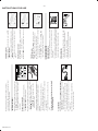
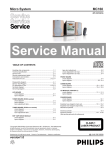
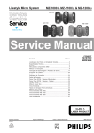
CD Stereo Radio Recorder
AZ1140
AZ1141
AZ1142
AZ1143
AZ1145
all versions
TABLE OF CONTENTS
chapter
Handling chip components and safety ............................. 1 - 1
Technical Specification & Service Tools.......................... 2 - 1
Service Measurement .................................................. 2 - 2
Connections & Controls ................................................ 3 - 1
Instructions for use ................................................. 3 - 2 to 3 - 6
Disassembly Diagram ................................................... 4 - 1
CD Service Test Program ........................................ 4 - 2 to 4 - 3
chapter
MAIN BOARD
circuit diagram ....................................................... 10 - 1
layout diagram ....................................................... 10 - 2
Block Diagram ............................................................. 5 - 1
Wiring Diagram ........................................................... 6 - 1
CD MODULE
circuit diagram ....................................................... 12 - 2
layout diagram ....................................................... 12 - 1
CONTROL BOARD
circuit diagram ................................................... 7 - 1, 7 - 3
layout diagram ....................................................... 7 - 2
SWITCH & VOLUME BOARD
layout diagram ....................................................... 8 - 1
RECORDER & BEAT CUT BOARD
circuit diagram ....................................................... 11 - 1
layout diagram ....................................................... 11 - 2
EXPLODED VIEWS DIAGRAM
cabinet ................................................................. 13 - 1
tape deck ............................................................ 13 - 2
Mechanical partslist ..................................................... 13 - 2
Electrical partslist ............................................... 14 - 1 to 14 - 4
TUNER BOARD
circuit diagram ....................................................... 9 - 1
layout diagram ....................................................... 9 - 2
Safety regulations require that the set be restored to its original
condition and that parts which are identical with those specified
be used.
CLASS 1
LASER PRODUCT
C
Copyright 1995 Philips Consumer Electroncis B.V. Eindhoven,The Netherlands
All rights reserved. No part of this publication may be reproduced, stored in a retrieval
system or transmitted, in any form or by any means, electronic, mechanical, photocopying,
or otherwise without the prior permission of Philips.
Published by SS 0024 Service Audio
PCS 104 409
Printed in The Netherlands
Copyright reserved
Subject to modification
GB
3140 785 22260
2-1
TECHNICAL SPECIFICATIONS
GENERAL
Mains voltage
Mains frequency
Battery
Power consumption
TUNER - AM SECTION
-/00
-/01/11/16
-/05/10
-/17
-/00/05/10
-/01/11/16
-/17
mains
Remote
normal
standby
Dimension (W x H x D)
Weight
:
:
:
:
:
:
:
:
:
:
:
:
:
230 V
120/230 V
240 V
120 V
50 Hz
50 / 60 Hz
60 Hz
9 V (R14 x 6)
3V (R03 x 2)
10 W
2W
290 x 152 x 253 mm
2.6 Kg
Tuning range
MW : 531 - 1602 kHz
-/17 : 520 - 1730 kHz
LW : 153 - 279 kHz
: 450 kHz ± 1 kHz
MW : 64 dBu at 26dB S/N
LW : 70 dBu at 26dB S/N
IF frequency
Sensitivity
Selectivity
MW : 22dB
IF rejection ratio
Image rejection ratio
LW
MW
LW
MW
LW
:
:
:
:
:
29 dB
70 dB
70 dB
32 dB
35 dB
AUDIO CASSETTE RECORDER
AMPLIFIER
Output power
Speaker impedance
Frequency response
mains : 2 x 1.6 W
battery : 2 x 2 W
: 2 x 4 ohm
: 100 Hz - 8 kHz (±3dB)
:
:
:
P/B :
:
± 3%
< 0.35 % JIS WTD
< 120 sec.
125 – 6.3 kHz
45 dB
COMPACT DISC
TUNER - FM SECTION
Tuning range
IF frequency
Sensitivity
Selectivity
IF rejection
Image rejection
Tape speed accuracy
Wow & flutter
Fast wind/rewind C60
Frequency response
S/N ratio
:
:
:
:
:
:
87.5 - 108 MHz
10.7 MHz ± 0.2 MHz
16 dBf at 26dB S/N
55 dB at ± 300kHz
85 dB
40 dB
Frequency response
S/N ratio
Channel difference
Channel crosstalk
Laser wavelength
Laser light power
:
:
1 kHz :
1 kHz :
:
:
100 Hz - 10 kHz
> 50 dB
< 3 dB
> 26 dB
780 ± 20nm
< 0.3 mW
SERVICE TOOLS
Audio signal disc SBC 429.......................................................................4822 397 30184
Playability test disc SBC 444...................................................................4822 397 30245
Test disc 5 (disc without errors ) +
Test disc 5A (disc with dropout errors, black spots and fingerprints)
SBC 426/426A.....................................................................4822 397 30096
Burn in test disc (65 min. 1kHz signal at -30 dB level without “pause”) .....4822 397 30155
Universal test cassette Fe SBC 420 ........................................................4822 397 30071
PCS 104 410
*
TAPE
CD MO
OFF
VO L
USE
STOP
PLAY•PA
B OO ST
DY NA MI C
BA SS
DE
TU NE R
BATT
LOW
DB B
CD
PAU
SE
DY
NA
SS
%
BA
BO
T UN
OS
ER
RDER
H
SEARC
RECO
145
CASS
ETTE
ITA
L
M IC
D IG
AZ1
DIO
CD RA
REPEAT
ALL
CD
PROGRAM
P•OPEN
STO
234 5
!@ #$
1
T
(
PROGRA
M
SEA RCH
REMOTE
SENSOR
RECOR
D
£
™
¡
)
(
^ &
PLAY
67 5
2
4
6
9
1
8
2
l
ND
REPE
AT
TUNIN
G
SEAR
CH
eC
ontro
tal R
emot
STO
LE
BA
VOLU
ME
ET
P
ES
PRES
ET
PR
SHUFF
SEAR
CH
Digi
3
9 0
1
3
5
7
8
1 VOLUME 3,4 – adjusts volume level
2 PRESET 3,4 (up, down) – selects a preset
radio station
3 TUNING ∞, § (down, up) – tunes to radio
stations
4 SHUFFLE – to play CD tracks in random order
5 REPEAT – repeats a track/ CD programme/
entire CD
6 2; – starts and pauses CD playback/
interrupts CD playback
7 ¡, ™ – skips to the beginning of a current
track/ previous/ later track
8 STOP 9 – stops CD playback or erases a
CD programme
9 SEARCH 5, 6 – searches backwards or
forwards within a track/CD
REMOTE CONTROL
* p - 3.5 mm stereo headphone socket
( Telescopic aerial - improves FM reception
) BEAT CUT switch - eliminates possible
whistle tones during
MW (AM) recordings
¡ AC Mains - inlet for mains lead
™ Battery compartment - for six batteries,
type R-14, UM-2 or C-cells
£ Voltage selector (located inside the battery
compartment. Some versions only) - select
the correct local voltage 110/220 V before
plugging in the set
BACK PANEL
& PROGRAM Tuner - programmes preset radio stations;
CD - programmes tracks and reviews the
programme
Use of controls or adjustments or performance of procedures other than herein
may result in hazardous radiation exposure or other unsafe operation.
CAUTION
1 POWER slider - selects the sound source
for CD/ TUNER/ TAPE OFF and also switches
the set off
2 VOL +, – - adjusts the volume level
3 BATT LOW - indicates when battery power
is running low
4 DBB (Dynamic Bass Boost) - enhances
the bass
5 OPEN•CLOSE - opens/ closes the CD door
6 CASSETTE RECORDER keys
RECORD 0 - starts recording
PLAY 1 - starts playback
SEARCH 5/ 6 - fast winds/rewinds the tape
STOP•OPEN 9/ - stops the tape;
- opens the cassette
compartment
PAUSE ; - interrupts recording or playback
7 Remote sensor - infrared sensor for the
remote control
8 1-3 - programmes and selects your favourite
three radio stations
9 PRESET 3, 4 - (down, up) selects preset
tuner stations
0 BAND - selects waveband
! PLAY PAUSE 2; - starts /pauses
CD playback
@ CD MODE - selects a different play mode
e.g. SHUFFLE/ REPEAT CD
tracks or programme in random
/repeated order
# STOP 9 - stops CD playback or erase a CD
programme;
activates/ deactivates display
demo mode.
$ Cassette door
% Display - shows the status of the set
^ SEARCH ∞/ §
Tuner: (down, up) tunes radio stations.
CD: - searches back and forward within a
track;
- skips to the beginning of a current
track/ previous/ later track
TOP AND FRONT PANELS
3-1
CONNECTIONS AND CONTROLS
PCS 104 411
PCS 104 412
Using AC MAINS
1. Check if the mains voltage as shown on the type plate on
the base of the set, corresponds to your local mains supply. If
it does not, consult your dealer or service centre.
2. If your set is equipped with a voltage selector, adjust the
selector so that it matches with the local mains supply.
3. Connect the mains lead to the wall socket and the set is now
ready for use.
4. To disconnect the set from the mains supply completely,
remove the plug from the wall socket.
• Batteries contain chemical substances, so they should
be disposed of properly.
2. Replace the compartment door, making sure the batteries are
firmly and correctly in place. The set is now ready to operate.
– If BATT LOW lights up, battery power is running low.
– The BATT LOW indicator eventually goes out if the
batteries are too weak.
Incorrect use of batteries can cause electrolyte leakage and will
corrode the compartment or cause the batteries to burst.
Therefore:
• Do not mix battery types: e.g. alkaline with carbon zinc.
Only use batteries of the same type for the set.
• When inserting new batteries, do not try to mix old batteries
with the new ones.
• Remove the batteries if the set is not to be used for a long
time.
Remote control (supplied)
Open the battery compartment and insert two batteries,
type AAA, R03 or UM4 (preferably alkaline).
1. Open the battery compartment and insert six batteries, type
R-14, UM-2 or C-cells, (preferably alkaline) with the correct
polarity as indicated by the "+" and "-" symbols inside the
compartment.
BATTERIES (OPTIONAL)
Whenever convenient, use the mains supply if you want to
conserve battery life. Make sure you remove the plug from the set
and wall socket before inserting batteries.
AC ~ MAINS
6 x R14 • UM-2 • C-CELLS
• Place the set on a hard and flat surface so that the system
does not tilt. Make sure there is adequate ventilation to
prevent the system from overheating.
• The mechanical parts of the set contain self-lubricating
bearings and must not be oiled or lubricated.
Safety information
• Do not expose the set, batteries, CDs or cassettes to humidity,
rain, sand or excessive heat caused by heating equipment or
direct sunlight.
• To clean the set, use a soft, slightly dampened chamois leather.
Do not use any cleaning agents containing alcohol, ammonia,
benzene or abrasives as these may harm the housing.
General maintenance
GENERAL INFORMATION
PHILIPS demo mode
1. On the set, press the CD STOP 9 button for 5 seconds.
™ PH..IL ..IPS scrolls across the display continuously.
2. To return to the current display you can either:
• press any function button on the front panel. This interrupts the
demo mode for 30 seconds;
• press the CD STOP 9 button for 5 seconds. PH..IL ..IPS
scrolls once before the demo mode is cancelled.
Adjusting volume and sound
1. Press the VOL +, – controls to increase or decrease VOLUME
(or press 3 or 4 on the remote control).
2. Adjust the DBB control to select dynamic bass boost on or off.
Switching on and off
• Adjust the POWER slider to the desired sound source: CD,
TUNER or TAPE/OFF.
• The set is switched off when the POWER slider is in the
TAPE/OFF position and the keys on the tape deck are released.
™ The volume and tuner presets will be retained in the set's
memory.
TAPE
TUNER
VOL
BATT
LOW
DBB
CD
TUNER
VOL
BATT
LOW
P
STO
PLAY•PAU
SE
DYNAMIC
BASS
BOOST
DBB
PLAY•PAU
SE
DYNAMIC
BASS
BOOST
DBB
CD
PLAY•PAU
SE
DYNAMIC
BASS
BOOST
CD MOD
E
OFF
TAPE
OFF
PAUSE
PAUSE
PAUSE
STOP
REPEAT
ALL
CD
PROGRAM
•OPE
N
REPEAT
ALL
CD
PROGRAM
STOP
•OPE
N
REPEAT
ALL
CD
PROGRAM
STOP
•OPE
N
SEAR
CH
SEAR
CH
SEAR
CH
PLAY
RD
RD
RD
PROGRAM
REMOTE
SENSOR
RECO
REMOTE
SENSOR
RECO
REMOTE
SENSOR
RECO
SEARCH
PLAY
PLAY
INSTRUCTIONS FOR USE
3-2
TUNING TO RADIO STATIONS
Tuning to preset stations
Press 1, 2, 3 or PRESET 4 or 3 until the desired preset station is
displayed.
REPEAT
ALL
CD
PROGRAM
STOP
•OPE
N
REPEAT
ALL
CD
PROGRAM
N
REPEAT
ALL
CH
CH
SEAR
CH
SEAR
SEAR
CD
PROGRAM
N
STOP
•OPE
STOP
•OPE
Programming radio stations
You can store up to a total of 30 radio stations in the memory.
1. Tune to your desired station (see Tuning to radio stations).
2. Press PROGRAM to activate programming.
– Display: PROGRAM flashes.
3. Press PRESET 4 or 3 once or more to allocate a number from
1 to 30 to this station.
4. Press PROGRAM again to confirm the setting.
– Display: PROGRAM disappears, the preset number and the
frequency of the preset station are shown.
5. Repeat the above four steps to store other stations.
– You can overwrite a preset station by storing another frequency
in its place.
Favourite station selection
For your favourite 3 tuner stations, you can use the easy one-touch
programming and selection 1, 2 or 3 buttons.
1. Tune to your desired station (see Tuning to radio stations).
2. To store your station, press 1, 2 or 3 for 2 seconds or more.
™ Display: shows PROGRAM briefly, your favourite preset station
number and the tuner frequency.
To improve radio reception
– For FM, pull out the telescopic aerial. Incline and turn the
aerial. Reduce its length if the signal is too strong (very close
to a transmitter).
– For MW (AM), the set is provided with a built-in aerial so the
telescopic aerial is not needed. Direct the aerial by turning the
whole set.
1. Select TUNER source.
™
is displayed briefly and then the radio station
frequency is shown.
2. Press BAND once or more to select your waveband.
3. Press SEARCH ∞ or § and release when the frequency in
the display starts running.
™ The tuner automatically tunes to a station of sufficient
reception. Display shows
during automatic tuning.
™ If an FM station is received in stereo, STEREO is shown.
4. Repeat step 3 if necessary until you find the desired station.
• To tune to a weak station, press SEARCH ∞ or § briefly and
repeatedly until you have found optimal reception.
5. Adjust the power slider to TAPE/OFF position to switch off the
set.
PLAY
PROGRAM
REMOTE
SENSOR
RD
PROGRAM
REMOTE
SENSOR
RD
PROGRAM
RECO
RECO
RD
REMOTE
SENSOR
RECO
SEARCH
SEARCH
SEARCH
PLAY
PLAY
1
1
2
2
1
3
3
2
PR
ES
ES
ET
PR
3
ET
PR
BA
ND
FM
ND
ND
TUNER
STEREO
BA
ET
BA
ES
• Press SEARCH ∞ or § (on the remote control ¡ or ™) once or
repeatedly until the desired track number appears in the display.
• If you have selected a track number shortly after loading a CD or
in the PAUSE position, you will need to press PLAY•PAUSE 2;
to start playback.
Selecting a different track
Note: CD play will also stop when:
– the CD door is opened;
– the CD has reached the end
(unless you have selected REPEAT or REPEAT ALL);
– you select another source: TAPE / TUNER.
1. Select CD source.
™
is displayed briefly.
2. Lift the CD door open.
™ Display:
when you open the CD door.
3. Insert a CD or CD-R(W) with the printed side facing up and
close the CD door.
™ Display: d1SC flashes as the CD player scans the contents of a
CD. The total number of tracks and playing time are then shown.
Display:
is shown if the CD-R(W) is blank or not finalised.
4. Press PLAY•PAUSE 2; (on the remote control 2;) to start
playback.
™ Display: Current track number and elapsed playing time of the
track during CD playback.
5. To pause playback press PLAY•PAUSE 2;.
Press PLAY•PAUSE 2; again to resume play.
™ The display freezes and the elapsed playing time flashes when
playback is paused.
6. To stop CD playback, press STOP 9.
Playing a CD
In North and South America the frequency step between adjacent
channels in the AM and FM band are 10 KHz and 100 KHz
respectively. In the rest of the world this step is 9 KHz and 50 KHz.
Usually the frequency step has been preset in the factory for your area.
1. Check that the set is in the TAPE/OFF position and switched off.
2. To select 9KHz : press CD MODE and PROGRAM simultaneously.
Release the controls only when you switch on the set.
• To select 10KHz: press CD MODE and SEARCH § simultaneously.
Release the controls only when you switch on the set.
™ When tuning to radio stations, the display shows tuning in
either steps of 9 or 10.
™ All preset stations will be affected and you may need to
reprogramme your presets.
Changing tuning grid (some versions only)
TAPE
VOL
DBB
PLAY•PAU
SE
CD MOD
E
P
STO
PLAY•PAU
SE
P
STO
PLAY•PAU
SE
PAUSE
PAUSE
PAUSE
P
STO
TUNER
BATT
LOW
DBB
CD
DYNAMIC
BASS
BOOST
DYNAMIC
BASS
BOOST
CD MOD
E
OFF
CD MOD
E
PLAY•PAU
SE
STOP
REPEAT
ALL
CD
PROGRAM
•OPE
N
REPEAT
ALL
CD
PROGRAM
•OPE
N
STOP
STOP
REPEAT
ALL
REPEAT
ALL
CD
PROGRAM
•OPE
N
CD
PROGRAM
STOP
•OPE
N
PAUSE
SEAR
CH
SEAR
CH
SEAR
CH
SEAR
CH
RD
PROGRAM
REMOTE
SENSOR
RECO
PROGRAM
REMOTE
SENSOR
RD
REMOTE
SENSOR
RD
PROGRAM
RECO
SEARCH
RD
REMOTE
SENSOR
RECO
SEARCH
RECO
SEARCH
PLAY
PLAY
PLAY
PLAY
1
1
1
2
1
INSTRUCTIONS FOR USE
3-3
PCS 104 413
PCS 104 414
In the STOP position, press and hold down PROGRAM for a while
until the display shows all your stored track numbers in sequence.
Reviewing the programme
Programme in the STOP position to select and store your CD tracks
in the desired sequence. If you like, store any track more than
once. Up to 20 tracks can be stored in the memory.
1. Use the SEARCH ∞ or § on the set (on the remote control ¡
or ™), to select your desired track number.
2. Press PROGRAM.
™ Display: PROGRAM and the selected track number.
appears briefly.
™ If you attempt to programme without first selecting a track
number,
is shown.
3. Repeat steps 1-2 to select and store all desired tracks.
™
is displayed if you attempt to programme more than
20 tracks.
4. To start playback of your CD programme, press
PLAY•PAUSE 2;.
Programming track numbers
You can select and change the various play modes before or during
playback. The play modes can also be combined with PROGRAM.
SHUFFLE - tracks of the entire CD/ programme are played in
random order
SHUFFLE and REPEAT ALL - to repeat the entire CD/ programme
continuously in random order
REPEAT ALL - to repeat the entire CD/ programme
REPEAT - to play the current track continuously
1. To select your play mode, press the CD MODE key (or
SHUFFLE or REPEAT on the remote control) before or during
playback until the display shows the desired function.
2. Press PLAY•PAUSE 2; to start playback if in the STOP position.
3. To return to normal playback, press the CD MODE key or the
respective SHUFFLE or REPEAT key until the various SHUFFLE
/ REPEAT modes are no longer displayed.
– You can also press STOP 9 to cancel your play mode.
Different play modes: SHUFFLE and REPEAT
Note: During a CD programme or if SHUFFLE/ REPEAT active,
searching is only possible within a track.
1. Press and hold down SEARCH ∞ or §.
™ The CD is played at high speed and low volume.
2. When you recognize the passage you want,
release SEARCH ∞ or §.
– Normal playback continues.
Finding a passage within a track
E
CD MOD
P
STO
PAUSE
P
STO
SE
PLAY•PAU
E
PAUSE
CD RAD
ER
CH
SEAR
PLAY
CH
SEAR
RECORD
45
ER
SETTE
AZ 11
IO CAS
REPEAT
ALL
CD
PROGRAM
N
REPEAT
ALL
CD
PROGRAM
N
STOP
•OPE
RECORD
45
SETTE
STOP
•OPE
IO CAS
AZ 11
REPEAT
ALL
CD
PROGRAM
CD RAD
SE
PLAY•PAU
DYNAMIC
BASS
BOOST
CD MOD
P
STO
CD
PROGRAM
E
CD MOD
SE
PLAY•PAU
PLAY
RD
RD
PROGRAM
REMOTE
SENSOR
RECO
PROGRAM
REMOTE
SENSOR
RECO
SEARCH
SEARCH
PLAY
PROGRAM
SEARCH
RD
REMOTE
SENSOR
RECO
1. Select TAPE source.
™ The display shows tAPE throughout tape operation.
2. Press STOP•OPEN 9/ to open the cassette door.
3. Insert a recorded cassette and close the cassette door.
4. Press PLAY 1 to start playback.
5. To interrupt playback, press PAUSE ;. To resume, press the
key again.
8. By pressing SEARCH 5 or 6 on the set,fast winding of the
tape is possible in both directions.
9. To stop the tape, press STOP•OPEN 9/.
– The keys are automatically released at the end of the tape
and the tAPE indication goes out, except if PAUSE ; has
been activated.
PLAYING A CASSETTE
CD player and CD handling
• If the CD player cannot read CDs correctly, use a commonly
available cleaning CD to clean the lens before taking the set to
repair. Other cleaning methods may destroy the lens.
• The lens of the CD player should never be touched!
• Sudden changes in the surrounding temperature can cause
condensation to cloud over on the lens of your CD player.
Playing a CD is then not possible. Do not attempt to clean the
lens but leave the set in a warm environment until the
moisture evaporates.
• Always keep the CD compartment closed to avoid dust on
the lens.
• To take a CD out of its box, press the centre spindle while
lifting the CD. Always pick up the CD by the edge and return
the CD to its box after use to avoid scratching and dust.
• To clean the CD, wipe in a straight line from the centre
towards the edge using a soft, lint-free cloth. Do not use
cleaning agents as they may damage the disc.
• Never write on a CD or attach any stickers to it.
Erasing a programme
You can erase the programme by:
– pressing STOP 9 once in the STOP position or twice during
playback. The display shows '
' briefly.
– pressing the CD door open;
– switching to TUNER/TAPE source.
TAPE
OFF
TUNER
VOL
BATT
LOW
PLAY•PAU
DYNAMIC
BASS
BOOST
SE
SE
PAUSE
STO
P
X
DBB
CD
CD MOD
E
PLAY•PAU
DYNAMIC
BASS
BOOST
PAUSE
REPEAT
ALL
CD
PROGRAM
STOP
•OPE
N
REPEAT
ALL
CD
PROGRAM
STOP
•OPE
N
SEAR
CH
SEAR
CH
PLAY
PLAY
RD
REMOTE
SENSOR
RECO
PROGRAM
SEARCH
RD
REMOTE
SENSOR
RECO
1
1
2
INSTRUCTIONS FOR USE
3-4
GENERAL INFORMATION ON RECORDING
To select and record a particular passage within a track
• Press and hold down SEARCH ∞ or § (or on the remote
control 5 or 6).
• When you recognize the passage you want, release SEARCH ∞
or § (or on the remote control 5 or 6).
• To pause CD playback press PLAY/PAUSE 2;.
• Recording will begin from this exact point in the track when
you press RECORD 0.
6. For brief interruptions during recording press PAUSE ;. To
resume recording, press PAUSE ; again.
7. To stop recording, press STOP•OPEN 9/.
1. Select CD source.
2. Insert a CD and if desired, programme track numbers.
3. Press STOP•OPEN 9/ to open the cassette door.
4. Insert a suitable cassette into the cassette deck and close the
cassette door.
5. Press RECORD 0 to start recording.
– Playing of the CD programme starts automatically from the
beginning of the programme. It is not necessary to start the CD
player separately.
SYNCHRO START CD RECORDING
• Recording is permissible insofar as copyright or other rights of
third parties are not infringed.
• This deck is not suitable for recording on CHROME (IEC II) or
METAL (IEC IV) type cassettes. For recording, use NORMAL
type cassettes (IEC I) on which the tabs have not been broken.
• The best recording level is set automatically. Altering the VOL
and DBB controls will not affect the recording in progress.
• At the very beginning and end of the tape, no recording will
take place during the 7 seconds, when the leader tape passes
the recorder heads.
• To protect a tape from accidental erasure, have the tape in
front of you and break out the left tab.
Recording on this side is no longer possible. To record over this
side again, cover the tabs with a piece of adhesive tape.
TAPE
TUNER
VOL
BATT
LOW
E
PAUSE
E
P
STO
PLAY•PAU
PAUSE
REPEAT
ALL
CD
PROGRAM
N
STOP
•OPE
SE
DBB
DYNAMIC
BASS
BOOST
CD MOD
P
STO
PLAY•PAU
SE
DBB
CD
DYNAMIC
BASS
BOOST
CD MOD
OFF
REPEAT
ALL
CD
PROGRAM
N
STOP
•OPE
CH
SEAR
CH
SEAR
PLAY
SEARCH
PLAY
RD
PROGRAM
REMOTE
SENSOR
RECO
SEARCH
REMOTE
SENSOR
RD
RECO
1
2
TAPE
TUNER
VOL
BATT
LOW
PLAY•PAU
SE
DBB
CD
DYNAMIC
BASS
BOOST
CD MOD
E
OFF
STOP
N
REPEAT
ALL
CD
PROGRAM
•OPE
SEAR
CH
C B A
PAUSE
A
PLAY
RD
REMOTE
SENSOR
RECO
Your set consists of materials which can be recycled if disassembled by a specialized
company. Please observe the local regulations regarding the disposal of packing
materials, exhausted batteries and old equipment.
All unnecessary packaging material has been omitted. We have done our utmost to make the
packaging easy to separate into three mono-materials: cardboard (box), expandable polystyrene
(buffer), polyethylene (bags, protective foam).
Environmental information
Tape deck maintenance
To ensure quality recording and playback of the tape deck, clean
parts A,B and C shown in the diagram below, after approx.
50 hours of operation, or on average once a month. Use a cotton
bud slightly moistened with alcohol or a special head cleaning
fluid to clean the deck.
1. Open the cassette door by pressing STOP•OPEN 9/.
2. Press PLAY 1 and clean the rubber pressure rollers C.
3. Press PAUSE ; and clean the magnetic heads A and also the
capstan B .
4. After cleaning, press STOP•OPEN 9/.
Note: Cleaning of the heads can also be done by playing a
cleaning cassette through once.
MAINTENANCE
Recording from the radio
1. Tune to the desired radio station (See TUNING TO RADIO
STATIONS).
2. Press STOP•OPEN 9/ to open the cassette door.
3. Insert a suitable cassette into the cassette deck and close the
cassette door.
4. Press RECORD 0 to start recording.
• If you are recording from MW (AM) stations, adjust the
BEAT CUT switch to eliminate possible whistle tones during
recording.
5. For brief interruptions, press PAUSE ;. To resume recording,
press PAUSE ; again.
6. To stop recording, press STOP•OPEN 9/.
1
INSTRUCTIONS FOR USE
3-5
PCS 104 415
PCS 104 416
–
•
–
•
indication
CD-R(W) is blank or the disc is not finalised
Use a finalised CD-R(W)
CD badly scratched or dirty
Replace/ clean CD, see CD player and
CD handling
Remote control does not function properly
– Batteries dead/ incorrectly inserted
• Insert (fresh) batteries correctly
– Distance/ angle between the set too large
• Reduce the distance/ angle
Recording does not work
– Cassette tab(s) may be broken
• Apply a piece of adhesive tape over the
missing tab space
Poor cassette sound quality
– Dust and dirt on the heads, etc.
• Clean deck parts etc., see Maintenance
– Use of incompatible cassette types (METAL
or CHROME)
• Only use NORMAL (IEC I) for recording
The CD skips tracks
– CD is damaged or dirty
• Replace or clean the CD
– SHUFFLE or a programme is active
• Switch off SHUFFLE/PROGRAM
–
•
–
•
The typeplate is located on the bottom of the set.
or
indication
No CD inserted
Insert a CD
CD badly scratched or dirty
Replace/ clean CD, see CD player and
CD handling
– Laser lens steamed up,
• Wait until lens has cleared
Poor radio reception
– Weak radio signal
• FM: Direct the FM telescopic aerial for
optimum reception
• MW (AM): Turn the set for optimum
reception
Severe radio hum or noise
– Electrical interference: set too close to TV,
VCR or computer
• Increase the distance
No sound/power
– Volume not adjusted
• Adjust the volume
– Headphones connected
• Disconnect headphones
– Mains lead not securely connected
• Connect the mains lead properly
PROBLEM
– POSSIBLE CAUSE
• REMEDY
circumstances should you try to repair the set yourself, as this would
invalidate the guarantee.
WARNING: Do not open the set as there is a risk of electric shock. Under no
If a fault occurs, first check the points listed below before taking the set for repair.
If you are unable to remedy a problem by following these hints, consult your dealer or service centre.
INSTRUCTIONS FOR USE
3-6
14-4
ELECTRICAL PARTSLIST - CD99 DA11
- RESISTORS 4888
4889
482205120008
482205120008
Jumper
Jumper
- COILS & FILTERS 1810
5803
482224273557
482215711231
Filter CST8,46MTW-TF01
Coil LAN02TB1R0J
- DIODES 6877
482213011564
Diode UDZ3.9B
- IC & TRANSISTORS 7800
7802
7803
7804
7807
482220917324
532220911517
532213060123
532220982941
532213042755
IC SAA7325H
IC PC74HCU04T
Trans BC807-40
IC LM358D
Trans BC847C
7808
7809
7810
7875
482220932852
482220932852
482220933165
482213060511
IC TDA7073A/N2
IC TDA7073A/N2
IC TDA1308T/N1
Trans BC847B
- MISCELLANEOUS 1800
1823
1824
8000
482226510925
482226511207
482226511207
482232012178
Connector 15P
Connector 6P
Connector 6P
Flexible Foil 15P
Note :Only these parts mentioned in the list are
normal service parts.
PCS 104 436
12-2
9
-
+
8
Vref
TRACK
1801
EYE-PATTERN
64
6,5V
12
3856
68K
22K
68K
2837
3858
3K9
22n
3757
61
60
58
57
56
54
53
51
47K
3872
2847
470p
10K
1823
basic version w/ 6p-connector
1
GNDA
470R
GNDA
GNDA
+10V
KILL
C
GNDA
3701
2702
3
270R
47n
2
8
COAX1/+5V
2
10R
COAX2/EBU
3
GNDA
+5V
SHIELD/EBU_GND
5803
+3.3V
1822
2703
@
220u
3,3V
1u
4,8V 33R
digital out circuitry (not for all versions)
100n
EBUGND
1
+5V
+3.3V
+3.3V
PORE
CL11|4
49
2853 10n
3889
SDA
@ 1K
4806
+5V
.............
V EVM
F
V
DATA
SICL
5
SILD
150R
GND
4
SCL
3881
D
PORE
2
3
BC847B
B3V9 UDZ 6877
3,9V
GND
EH-S
1824
basic version w/ 5p-connector
3880
7875
SBSY 48
+3.3V
3836
1K
3882 100R
10K
1K
2855
6
EBUGND
3883
EH-S
1
3704
1
3884
doorswitch
2
4K7
1R
5802
920927152B
4
GNDA
3788
3705
EBUGND
E
SFSY 47
+3.3V
+2.5V
4K7
E
1821
1
+3.3V
3887 10K
22p
47n
100n
100n
stuffed
270R
470R
not stuffed
not stuffed
3888
D
1K
GND
FE-ST-VK-N
3886 10K
47p
not stuffed
Jumper
not stuffed
not stuffed
100R
not stuffed
33R
1R
from
7800
DOBM
on
sheet1
3841 4K7
+3servo
5
7
KILL
@
@
+5V
6
+10V
3879
47K
10u
2852
2,5V
7
TDA 1308
8
7810-B
5V
8402
LDON
+5V
RIGHT
4
2851
470p
2,5V
5
GNDA
3
3878
B
LEFT
2
GNDA
3885 10K
D
coax out
7
50
GNDA
220u
D
470R
2701
2702
2703
2704
5802
3701
3702
3703
3705
optical out
2701
SUBCODE
PROCESSOR
DOEM
52
@
GNDA
2854
MICROCONTROLLER
INTERFACE
55
@
GNDA
10K
SCLK
EF
TEST2
DATA
WCLK
CL16
TEST1
RP
59
3870
0R 4804
22K
3831
3830
4K7
EBU
INTERF.
OUTPUT
STAGES
10u
+2.5V
D
SUB 46
22K
@
GNDA
SILD
RCK 45
470R
@ 0R
Vdc measured during PLAY
with normal CD or CD-R
Vdc measured during PLAY with CD-RW
SILD
6
E
+5V/doorsw
FE-ST-VK-N
285610n
@
@... for provision only
CD99 Schematic Part2 18081999
800mVpp
Innersw
D
M2
M1
TB = 0.5m s/div
2831
1u
@
0V
EBUGND
2830
+3servo
1u
D
Vref
+3servo
+3.3V
D
drive_recognition
D
+3.3V
SL
FO
1
to
DOBM dig. out circuitry
on
sheet 2
2
3
4
5
6
7
8
9
10
G
D
for digital out: 33E
RA
D
3863
+10V
VDD
_
DISC
10
8401 9
5,9V
3857
Vref
13 _
-
+
2840
5
3R3
3859 47K
47u
6
+
connect shielding
2
7
2839
6,2V
+
14
1
2838
-
SLIDE
62
@
SLIDE
47n
T=1s
during Focus search
16 +
6,1V
63
MOTO2
LDON
V4
HFREF
3V
100n
G
VERSATILE
INTERFACE
1
LOW = CD_RW (high gain)
7809
TDA7073A
MOTOR
CONTROL
2
2816 22n
EH-S
side entry connector
DACRIGHT_pos
DACRIGHT_neg
HFIN
VDDD1P
22K
HFIN
HF
10p
HF
3865
3825
1K
3874
to
1805
on
sheet 2
(uP-interface)
3840
VSSD2
47n
2814
2812
2n2
3
2815
Y
HF
D
ISLICE
PEAK
DET.
CFLG
3827
33R
33p
2811
A
3839 470R
A
2846
3871
10K
GNDA
4
2,5V
6
DACLEFT_pos
C
D
3843 1K 3842 1K
56K
3822
3824
SCL
2829 47n
3851
47K
L
ERROR
CORR.
DIG.
PLL
3844
3852
10 3821
2813
Vdd_HCU
of HCU
15K
3854
10
7802-E
VCC
3853
Y
8
22K
D
SDA
SCL 40
2,5V
1
TDA 1308
8
7810-A
5V
GNDA
DACLEFT_neg
STATUS 43
100R
6,0V
7
A
15K
D
47u
6
3819
11
33p
7802-D
9
FRONT
END
4
@
3873
C
3838 470R
TEST3 44
2,5V
3
10K
3876
PORE
47p
10
2850
DRIVE = DA11
digital out = off
2828
9
220p
D
RAB 41
SRAM
3751
6
82K
Y
3K3
3837 470R
VSSA1
HF
3K3
3K3
D
SDA 39
ADDR
5
1u
_
8K2
5
+
DISC
-
VDD
12
+
TRACK
A
2 2810
2842
6,2V
Innersw
3847
47K
+t
PTH8
2835
4
3848
+10V
2836
7802-A
1
33p
56K
3855
10V
2809
7802-B
Vref
5
4
18K
EFM
DEMOD
VDDA1
3823
2827 1n
8
+2.5V
IREF
DA
22K
D
D
7
4
B
drive_recognition
SILD 42
6
HF
HF
3820
5K6
Y
2832
13
A
2834
6,1V
2
_
2
3
15K
3
47K
3818
0,9V 0,9V
VREF GEN.
7
HF
2817 4u7
VRIN
27K 3826
3817
150p
+
14
8K2
FOCUS
1
6
3814
1
BC847C
7807
L
270p
82p
-
15
3816
3849
3850
16
0,9V 0,9V
1,5V 0V
3K3
470p
6,2V
INNERSW.
H
47n 2818
3750
22K
2875
220p
2865
D1
HF-Amplifier
68K
Y
+
14
SLIDE
+
A
FOCUS
13
T+
F-
FOCUS
3815
3813
7808
TDA7073A
L
2833
TRACK
2808
7802-C
27p
47n 2869
12
TF+
5
HF
LASER
470K 3812
4K7
150p
1K
2807
L
11
L
82p
Monitor
10
E
F
9
3811
470p
M
L
2806
8
2804 82p
7
A
2805
6
AUDIO
PROCESSOR
8
+3.3V
DA
HF
KILL
SDI 36
2,5V
2
DACRIGHT_neg
GNDA
3835 22K
7810-A A5
7810-B C5
7875 E7
8402 C9
3869
3900
KILL
D
4805 C4
4806 E9
5802 D3
5803 E6
6877 E7
6
GNDA
A
@
3834 22K @
3887 E9
3888 E9
3889 E10
3900 A5
4804 A4
220p
A
D
3882 D7
3883 D6
3884 D6
3885 E8
3886 E8
5
3867
RESETn 38
9
D1 (CD10)
10K
5
C
E
180p
D
B
2803 82p
C
DA
3899
V5
4
A
HF
22K
3893
100K
V1
3
F
3829
VNEG
CONTROL
FUNCTION
3846
E
D
KILL
7800
10
4
B
VERSAT.
INTERF. V2|V3 34
SAA7325H
PROCESSING
ADC
22K
F
100R
DACLEFT_pos
PRE-
D3
220p
2874
180p
2864
LP
D4
3877 C6
3878 C7
3879 C8
3880 E7
3881 E7
2845
32
SCLI 37
11
47p
2
31
SER. DATA
LOOPBACK
INTERF.
D2
B
30
R1
D2 (CD10)
10K
29
WCLI 35
RA
100K
28
12
L
1
27
BITSTREAM DAC
FO
1800
3898
26
13
DA
3
3872 A8
3873 C5
3874 C5
3875 C5
3876 B6
DACRIGHT_pos
3832
VSSD1 33
SL
3892
25
3845 2R2
HF
284147n
24
R2
220p
10K
2
3867 A5
3868 A5
3869 A6
3870 A6
3871 A7
CD Part (sheet 2)
on
off
470R
14
D3 (CD10)
2873
180p
100K
3864 10K
@
VSSA2
DA
3897
2863
C
D
15
D
3703 D3
3704 E4
3705 D3
3788 E9
3836 D10
+5V
3745 10R
HF
3891
D
1
2855 D6
2856 E10
2857 E6
3701 E1
3702 E2
22K
SER. DATA
INTERFACE
VSSD3
10K
220p
2872
100K
180p
2862
LASER
CROUT
2850 B6
2851 C7
2852 C8
2853 E6
2854 D6
+3.3V
D4 (CD10)
1n5
22
23
SELPLL
16
3896
Laser power control
VDDA2
CRIN
8.46 MHz
DA
2825
47n
20
21
VDDD2C
HF
3890
47n
DA11
DA11
D
RN
2820
33p
1n5
18
19
TIMING
2871
2861
1,8V
10K
3834
3835
2845 A6
2846 A7
2847 A8
2848 C5
2849 C5
GNDA
220u
2824
1810
R1 (CD10)
17
L
comm. cath
15
table for drive- and digital out recognition
stuffed resistor
drive
digital out
3750
VAM
on
3751
VAM
off
2823
2822
DA
3895
7803
BC807-40
+5V
33p
2819
220p
2870
HF
L
SANYO DA11
D
LN
3,9V
3,3V
LDON L Monitor
14
2826
R2 (CD10)
10K
560p
2860
47u
2802
3808 33R
47u
3802
4K7
1K
3804
3894
220p
4
D
only for digital out versions
(Quartz used)
1n5
680R
2
2801
3809 33R
3807 1K5
7804-A
LM358D
1 2,5V
8
3806
3
DACLEFT_neg
47R
2821
47R
4R7
3800 4R7
3801
150K
3805 27K
3803 27K
3828
+5V
0,2V
B
3728
100n
+3.3V
3810
0,2V
13
2702 E2
2703 E4
2704 E3
2843 A5
2844 A5
3877
12
+3.3V
Vdd_HCU
5V
1821 D10
1822 E4
1823 B10
1824 D10
2701 E2
11
CD Part (sheet 1)
A
7808 E4
7809 G4
8401 H3
47u
10
7802-D E8
7802-E E7
7802-F F8
7803 B2
7804-A A1
7804-B C3
7807 E6
2857
9
3897 C5
3898 C5
3899 D5
7800 D12
7802-A E6
7802-B E5
7802-C E5
2843
3890 B4
3891 C4
3892 C4
3893 D4
3894 A5
3895 B5
3896 B5
100p
8
3859 H5
3860 H5
3861 H5
3862 H5
3863 H4
3864 C1
3865 F7
2844
10K
3852 F5
3853 F5
3854 F5
3855 F4
3856 G6
3857 G5
3858 G5
3868
7
3845 G12
3846 F10
3847 F6
3848 F5
3849 E5
3850 F5
3851 F6
2848
3838 D14
3839 D14
3840 D15
3841 E14
3842 G14
3843 G14
3844 G13
3875
6
3829 A11
3830 B12
3831 B14
3832 B14
3834 B14
3835 C14
3837 C14
220p
3822 E7
3823 E8
3824 E9
3825 E9
3826 D10
3827 D9
3828 A10
100p
5
3815 E5
3816 E5
3817 E7
3818 E6
3819 E6
3820 E7
3821 E7
2849
10K
4
3808 A2
3809 A2
3810 A3
3811 E4
3812 D5
3813 E5
3814 E5
220p
3801 A1
3802 B1
3803 B1
3804 B1
3805 A1
3806 B2
3807 A2
DIGout
3
2875 D5
3728 A10
3745 G12
3750 G11
3751 G11
3757 G5
3800 B2
0R 4805
2865 D5
2869 E2
2870 B5
2871 B5
2872 C5
2873 C5
2874 D5
3703 33R
2
2841 C1
2842 F7
2860 B5
2861 B5
2862 C5
2863 C5
2864 D5
2704
2834 F5
2835 F4
2836 F4
2837 G5
2838 G4
2839 H4
2840 H4
100n
1
2827 C14
2828 C14
2829 G14
2830 F13
2831 G12
2832 F5
2833 F4
470R
2820 B10
2821 B11
2822 B11
2823 B11
2824 B11
2825 B12
2826 A13
12-2
22p
2813 E9
2814 E9
2815 E10
2816 F10
2817 D9
2818 D9
2819 B10
VPOS
2806 E4
2807 E4
2808 E4
2809 E6
2810 E6
2811 F7
2812 E8
MOTO1
1800 D1
1801 G1
2801 A2
2802 A3
2803 E4
2804 E4
2805 E4
12-2
3702
CD99 DA11 - CIRCUIT DIAGRAM
3860 1K
M2
V EVM
3861 47K
DISC
3862 1K
.............
D
V
Vdc measured during PLAY with normal CD or CD-R
H
Vdc measured during PLAY with CD-RW
M1
@...
D
for provision only
CD99 Schematic Part1 18081999
1
2
3
4
5
6
7
8
9
10
11
12
13
14
15
PCS 99 484
13-1
13-1
13-1
EXPLODED VIEW DIAGRAM - CABINET
SCREW LIST
1. C2 x 10
2. C2 x 12
3. C2.5 x 9.5
4. C3 x 7.5
5. C3 x 8
6. C3 x 9
7. C3 x 10
8. C3 x 12
9. C3 x 34
10. C P/W 2.5 x 16
11. C P/W 3 x 10
12. C P/W 3 x 14
519
423
5 (2x)
424
521
422
VOL
UME
PRE
SET
TUN
ING
421
SHU
FFLE
REP
EAT
416
SEA
RCH
STO
P
SEA
RCH
419
447
Digit
al R
emote
Cont
rol
418
5
5
3 (3x)
414
518
417
513
517
413
8 (2x)
6 (2x)
1 (2x)
516
6
412
511
446
8 (4x)
439
2 (2x)
512
3 (3x)
407
438
408
437
8 (2x)
7 (2x)
502
11
409
509
442
436
514
404
403
406
444
434
11
443
433
6 (2x)
3 (2x)
441
508
3 (2x)
411
501
429
504
432
506
507
8 (2x)
4
8
402
428
531
5 (2x)
522
431
503
6 (2x)
9 (5x)
11
526
1
524
401
6 (2x)
427
426
529
6 (2x)
527
10 (4x)
523
6 (2x)
12 (2x)
5 (3x)
PCS 104 431
7 (2x)
528
5 (2x)