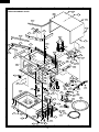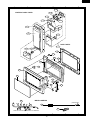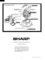
1
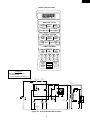
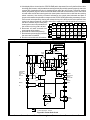
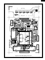
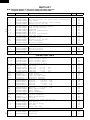
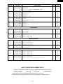
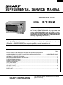
R-318BK
SUPPLEMENTAL SERVICE MANUAL
S915R318BPK/
MICROWAVE OVEN
MODEL
R-318BK
SENSOR COOK
POPCORN
BAKED
POTATO REHEAT
FRESH VEGETABLE FROZEN ENTREES
INSTANT ACTION
TO ADJUST QUANTITY . TOUCH
In the interest of user-safety the oven should be restored to its original
condition and only parts identical to those specified should be used.
PAD AGAIN
GROUND FRESH/ CHICKEN
MEAT
SEAFOOD BREAST
FRESH ROLL
FROZEN ROLL
COMPU DEFROST
GROUND
MEAT
STEAKS/ CHICKEN
CHOPS
PIECES
KITCHEN
TIMER
AUTO START
CLOCK
MINUTE
PLUS
POWER
LEVEL
STOP
CLEAR
START
WARNING TO SERVICE PERSONNEL: Microwave ovens contain circuitry capable of producing very high voltage and
current, contact with following parts may result in a severe,
possibly fatal, electrical shock. (High Voltage Capacitor, High
Voltage Power Transformer, Magnetron, High Voltage Rectifier
Assembly, High Voltage Harness etc..)
This is a supplemental Service Manual for Model R-318BK. This model is quite similar to base
model R-320BK. Use this supplemental manual together with the Base Model Service Manual
(Refer No. is S2805R320BPW/) for complete operation, service information, etc..
TABLE OF CONTENTS
Page
PRECAUTIONS TO BE OBSERVED BEFORE AND DURING SERVICING TO
AVOID POSSIBLE EXPOSURE TO EXCESSIVE MICROWAVE ENERGY ................... INSIDE FRONT COVER
BEFORE SERVICING ...................................................................................................... INSIDE FRONT COVER
WARNING TO SERVICE PERSONNEL ................................................................................................................ 1
MICROWAVE MEASUREMENT PROCEDURE ................................................................................................... 2
FOREWORD AND WARNING ............................................................................................................................... 3
PRODUCT SPECIFICATIONS .............................................................................................................................. 4
SCHEMATIC DIAGRAM ........................................................................................................................................ 5
TEST PROCEDURE .............................................................................................................................................. 6
POWER UNIT CIRCUIT ........................................................................................................................................ 7
CPU UNIT CIRCUIT .............................................................................................................................................. 8
PRINTED WIRING BOARD ................................................................................................................................... 9
PARTS LIST ........................................................................................................................................................ 10
PACKING AND ACCESSORIES ......................................................................................................................... 14
SHARP CORPORATION
This document has been published to be used for after
sales service only.
The contents are subject to change without notice.
R-318BK
PRECAUTIONS TO BE OBSERVED BEFORE AND
DURING SERVICING TO AVOID POSSIBLE
EXPOSURE TO EXCESSIVE MICROWAVE
ENERGY
(a) Do not operate or allow the oven to be operated with the door open.
(b) Make the following safety checks on all ovens to be serviced before activating the magnetron or other
microwave source, and make repairs as necessary: (1) interlock operation, (2) proper door closing, (3)
seal and sealing surfaces (arcing, wear, and other damage), (4) damage to or loosening of hinges and
latches, (5) evidence of dropping or abuse.
(c) Before turning on microwave power for any service test or inspection within the microwave generating
compartments, check the magnetron, wave guide or transmission line, and cavity for proper alignment,
integrity, and connections.
(d) Any defective or misadjusted components in the interlock, monitor, door seal, and microwave
generation and transmission systems shall be repaired, replaced, or adjusted by procedures described
in this manual before the oven is released to the owner.
(e) A microwave leakage check to verify compliance with the Federal Performance Standard should be
performed on each oven prior to release to the owner.
BEFORE SERVICING
Before servicing an operative unit, perform a microwave emission check as per the Microwave
Measurement Procedure outlined in this service manual.
If microwave emissions level is in excess of the specified limit, contact SHARP ELECTRONICS
CORPORATION immediately @1-800-237-4277.
If the unit operates with the door open, service person should 1) tell the user not to operate the oven
and 2) contact SHARP ELECTRONICS CORPORATION and The Food and Drug Administration's
Center for Devices and Radiological Health immediately.
Service personnel should inform SHARP ELECTRONICS CORPORATION of any certified unit found
with emissions in excess of 4mW/cm2. The owner of the unit should be instructed not to use the unit
until the oven has been brought into compliance.
R-318BK
WARNING TO SERVICE PERSONNEL
Microwave ovens contain circuitry capable of producing very high voltage and current, contact with
following parts may result in a severe, possibly
fatal, electrical shock.
(Example)
High Voltage Capacitor, High Voltage Power Transformer, Magnetron, High Voltage Rectifier Assembly, High Voltage Harness etc..
Read the Service Manual carefully and follow all
instructions.
Don't Touch !
Danger High Voltage
When the testing is completed,
1. Disconnect the power supply cord, and then remove
outer case.
2. Open the door and block it open.
3. Discharge high voltage capacitor.
4. Reconnect the leads to the primary of the power
transformer.
5. Reinstall the outer case (cabinet).
6. Reconnect the power supply cord after the outer case is
installed.
7. Run the oven and check all functions.
Before Servicing
1. Disconnect the power supply cord
remove outer case.
2. Open the door and block it open.
3. Discharge high voltage capacitor.
, and then
WARNING:RISK OF ELECTRIC SHOCK.
DISCHARGE THE HIGH-VOLTAGE
CAPACITOR BEFORE SERVICING.
The high-voltage capacitor remains charged about 60
seconds after the oven has been switched off. Wait for 60
seconds and then short-circuit the connection of the highvoltage capacitor (that is the connecting lead of the highvoltage rectifier) against the chassis with the use of an
insulated screwdriver.
After repairing
1. Reconnect all leads removed from components during
testing.
2. Reinstall the outer case (cabinet).
3. Reconnect the power supply cord after the outer case is
installed.
4. Run the oven and check all functions.
Whenever troubleshooting is performed the power supply
must be disconnected. It may in, some cases, be necessary
to connect the power supply after the outer case has been
removed, in this event,
1. Disconnect the power supply cord, and then remove
outer case.
2. Open the door and block it open.
3. Discharge high voltage capacitor.
4. Disconnect the leads to the primary of the power
transformer.
5. Ensure that the leads remain isolated from other
components and oven chassis by using insulation tape.
6. After that procedure, reconnect the power supply cord.
Microwave ovens should not be run empty. To test for the
presence of microwave energy within a cavity, place a cup
of cold water on the oven turntable, close the door and set
the power to HIGH and set the microwave timer for two (2)
minutes. When the two minutes has elapsed (timer at zero)
carefully check that the water is now hot. If the water
remains cold carry out Before Servicing procedure and reexamine the connections to the component being tested.
When all service work is completed and the oven is fully
assembled, the microwave power output should be checked
and microwave leakage test should be carried out.
1
R-318BK
MICROWAVE MEASUREMENT PROCEDURE
A. Requirements:
1) Microwave leakage limit (Power density limit): The power density of microwave radiation emitted by a microwave oven
should not exceed 1mW/cm2 at any point 5cm or more from the external surface of the oven, measured prior to acquisition
by a purchaser, and thereafter (through the useful life of the oven), 5 mW/cm2 at any point 5cm or more from the external
surface of the oven.
2) Safety interlock switches Primary interlock relay and door sensing switch shall prevent microwave radiation emission in
excess of the requirement as above mentioned, secondary interlock switch shall prevent microwave radiation emission
in excess of 5 mW/cm2 at any point 5cm or more from the external surface of the oven.
B. Preparation for testing:
Before beginning the actual measurement of leakage, proceed as follows:
1) Make sure that the actual instrument is operating normally as specified in its instruction booklet.
Important:
Survey instruments that comply with the requirement for instrumentation as prescribed by the performance standard
for microwave ovens, 21 CFR 1030.10(c)(3)(i), must be used for testing.
2) Place the oven tray in the oven cavity.
3) Place the load of 275±15 ml (9.8 oz) of tap water initially at 20±5˚C (68˚F) in the center of the oven cavity.
The water container shall be a low form of 600 ml (20 oz) beaker with an inside diameter of approx. 8.5 cm (3-1/2 in.)
and made of an electrically nonconductive material such as glass or plastic.
The placing of this standard load in the oven is important not only to protect the oven, but also to insure that any leakage
is measured accurately.
4) Set the cooking control on Full Power Cooking Mode
5) Close the door and select a cook cycle of several minutes. If the water begins to boil before the survey is completed,
replace it with 275 ml of cool water.
C. Leakage test:
Closed-door leakage test (microwave measurement)
1) Grasp the probe of the survey instrument and hold it perpendicular to the gap between the door and the body of the oven.
2) Move the probe slowly, not faster than 1 in./sec. (2.5 cm/sec.) along the gap, watching for the maximum indication on
the meter.
3) Check for leakage at the door screen, sheet metal seams and other accessible positions where the continuity of the metal
has been breached (eg., around the switches, indicator, and vents).
While testing for leakage around the door pull the door away from the front of the oven as far as is permitted by the closed
latch assembly.
4) Measure carefully at the point of highest leakage and make sure that the highest leakage is no greater than 4mW/cm2,
and that the secondary interlock switch does turn the oven OFF before any door movement.
NOTE: After servicing, record data on service invoice and microwave leakage report.
2
R-318BK
SERVICE MANUAL
MICROWAVE OVEN
R-318BK
FOREWORD
This Manual has been prepared to provide Sharp Electronics Corp. Service Personnel with Operation and Service
Information for the SHARP MICROWAVE OVEN, R-318BK.
The model R-318BK is quite similar to base model R-320BK (Refer No. is S2805R320BPW/).
It is recommended that service personnel carefully study the entire text of this manual and the base model's manual so
that they will be qualified to render satisfactory customer service.
Check the interlock switches and the door seal carefully. Special attention should be given to avoid electrical shock and
microwave radiation hazard.
WARNING
Never operate the oven until the following points are ensured.
(A) The door is tightly closed.
(B) The door brackets and hinges are not defective.
(C) The door packing is not damaged.
(D) The door is not deformed or warped.
(E) There is no other visible damage with the oven.
Servicing and repair work must be carried out only by trained service personnel.
DANGER
Certain initial parts are intentionally not grounded and present a risk of electrical shock only during servicing.
Service personnel - Do not contact the following parts while the appliance is energized;
High Voltage Capacitor, Power Transformer, Magnetron, High Voltage Rectifier Assembly, High Voltage
Harness;
If provided, Vent Hood, Fan assembly, Cooling Fan Motor.
All the parts marked “*” on parts list are used at voltages more than 250V.
Removal of the outer wrap gives access to voltage above 250V.
All the parts marked “∆” on parts list may cause undue microwave exposure, by themselves, or when they are
damaged, loosened or removed.
SHARP ELECTRONICS CORPORATION
SHARP PLAZA, MAHWAH,
NEW JERSEY 07430-2135
3
R-318BK
SPECIFICATION
ITEM
DESCRIPTION
Power Requirements
120 Volts / 14 Amperes
60 Hertz
Single phase, 3 wire grounded
Power Output
1100 watts (IEC-705 TEST PROCEDURE)
Operating frequency of 2450MHz
Width 20-1/2"
Height 11-7/8"
Depth 15-7/8"
Width 13-3/4"
Height 8-3/8"
Depth 14-7/8"
Case Dimensions
Cooking Cavity Dimensions
1.0 Cubic Feet
Control Complement
Touch Control System
Clock ( 1:00 - 12:59 )
Timer (0 - 99 min. 99 seconds)
Microwave Power for Variable Cooking
Repetition Rate;
P-HI .................................................. Full power throughout the cooking time
P-90 .................................................................... approx. 90% of Full Power
P-80 .................................................................... approx. 80% of Full Power
P-70 .................................................................... approx. 70% of Full Power
P-60 .................................................................... approx. 60% of Full Power
P-50 .................................................................... approx. 50% of Full Power
P-40 .................................................................... approx. 40% of Full Power
P-30 .................................................................... approx. 30% of Full Power
P-20 .................................................................... approx. 20% of Full Power
P-10 .................................................................... approx. 10% of Full Power
P-0 .................................................... No power throughout the cooking time
SENSOR COOK pads, INSTANT ACTION pads
COMPU DEFROST pads, Number selection pads
KITCHEN TIMER pad, AUTO START/CLOCK pad
MINUTE PLUS pad, POWER LEVEL pad
STOP/CLEAR pad, START pad
Oven Cavity Light
Safety Standard
Yes
UL Listed
FCC Authorized
DHHS Rules, CFR, Title 21, Chapter 1, Subchapter J
4
R-318BK
TOUCH CONTROL PANEL
SENSOR COOK
BAKED
POPCORN POTATO REHEAT
FRESH VEGETABLES FROZEN ENTREES
INSTANT ACTION
TO ADJUST QUANTITY . TOUCH PAD AGAIN
GROUND FRESH/ CHICKEN
SEAFOOD BREAST
MEAT
FRESH ROLL
FROZEN ROLL
COMPU DEFROST
GROUND
MEAT
STEAKS/
CHOPS
CHICKEN
PIECES
KITCHEN
TIMER
AUTO START
CLOCK
MINUTE
PLUS
POWER
LEVEL
STOP
CLEAR
START
SCHEMATIC
NOTE: CONDITION OF OVEN
1. DOOR CLOSED
2. CLOCK APPEARS ON DISPLAY
MONITOR
FUSE 20A
THERMAL
CUT-OUT (OVEN)
THERMAL
CUT-OUT (MG.)
COM.
POWER
TRANSFORMER
N.O.
CONTROL UNIT
N.O.
COM.
SH-B
GRN
120V AC
60 Hz
SH-A
DOOR
SENSING
SWITCH
TTM
OL
FM
CAPACITOR 1.0µF
AC 2300V
F1
PRIMARY
INTERLOCK
RELAY
F2
(RY-2)
(RY-1)
A1
AH SENSOR
F3
A2
MONITOR
SWITCH
RECTIFIER
MAGNETRON
OVEN
LAMP
TURNTABLE
MOTOR
FAN
MOTOR
SECONDARY
INTERLOCK
SWITCH
Figure O-1. Oven Schematic-Off Condition
5
R-318BK
TROUBLESHOOTING GUIDE
Never touch any part in the circuit with your hand or an uninsulated tool while the power supply is connected.
When troubleshooting the microwave oven, it is helpful to follow the Sequence of Operation in performing the checks. Many
of the possible causes of trouble will require that a specific test be performed. These tests are given a procedure letter which
will be found in the "Test Procedure "section.
IMPORTANT: If the oven becomes inoperative because of a blown monitor fuse, check the monitor switch, relay (RY1)
primary interlock relay (RY2), door sensing switch and secondary interlock switch before replacing the
monitor fuse. If monitor fuse is replaced, the monitor switch must also be replaced. Use part FFSBA021WRK0 as an assembly.
IMPORTANT: Whenever troubleshooting is performed with the power supply cord disconnected. It may in, some cases,
be necessary to connect the power supply cord after the outer case has been removed, in this event,
1. Disconnect the power supply cord, and then remove outer case.
2. Open the door and block it open.
3. Discharge high voltage capacitor.
4. Disconnect the leads to the primary of the power transformer.
5. Ensure that the leads remain isolated from other components and oven chassis by using insulation tape.
6. After that procedure, reconnect the power supply cord.
When the testing is completed
1. Disconnect the power supply cord, and then remove outer case.
2. Open the door and block it open.
3. Discharge high voltage capacitor.
4. Reconnect the leads to the primary of the power transformer.
5. Reinstall the outer case (cabinet).
6. Reconnect the power supply cord after the outer case is installed.
7. Run the oven and check all functions.
TEST PROCEDURES
PROCEDURE
LETTER
H
COMPONENT TEST
BLOWN MONITOR FUSE TEST
1.
2.
3.
4.
Disconnect the power supply cord, and then remove outer case.
Open the door and block it open.
Discharge high voltage capacitor.
If the monitor fuse is blown when the door is opened, check the primary interlock relay, secondary
interlock switch and monitor switch according to the "TEST PROCEDURE" for those switches before
replacing the blown monitor fuse.
CAUTION: BEFORE REPLACING A BLOWN MONITOR FUSE, TEST THE PRIMARY INTERLOCK
RELAY, SECONDARY INTERLOCK SWITCH, DOOR SENSING SWITCH AND MONITOR
SWITCH FOR PROPER OPERATION.
If the monitor fuse is blown by improper switch operation, the monitor fuse and monitor switch must
be replaced with "monitor fuse and monitor switch assembly" part number FFS-BA021WRK0, even
if the monitor switch operates normally. The monitor fuse and monitor switch assembly is comprised
of a 20 ampere fuse and switch.
5. Reconnect all leads removed from components during testing.
6. Reinstall the outer case (cabinet).
7. Reconnect the power supply cord after the outer case is installed.
8. Run the oven and check all functions.
J
KEY UNIT TEST
1. Disconnect the power supply cord, and then remove outer case.
2. Open the door and block it open.
3. Discharge high voltage capacitor.
6
R-318BK
4. If the display fails to clear when the STOP/CLEAR pad is depressed, first verify the flat ribbon cable
is making good contact, verify that the door sensing switch (stop switch) operates properly; that is the
contacts are closed when the door is closed and open when the door is open. If the door sensing
switch (stop switch) is good, disconnect the flat ribbon cable that connects the key unit to the control
unit and make sure the door sensing switch is closed (either close the door or short the door sensing
switch connecter). Use the Key unit matrix indicated on the control panel schematic and place a
jumper wire between the pins that correspond to the STOP/CLEAR pad making momentary contact.
If the control unit responds by clearing with a beep the key unit is faulty and must be replaced. If the
control unit does not respond, it is faulty and must be replaced. If a specific pad does not respond,
the above method may be used (after
G8
G7
G6
G5
G4
G3
G2
G1
clearing the control unit) to determine if
Reheat
Popcorn
2
1
G9
3
5
4
the control unit or key pad is at fault.
5. Reconnect all leads removed from
Baked
KITCHEN
Fresh
G10
0
9
8
7
6
potato Vegetables
TIMER
components during testing.
Ground
meat
6. Re-install the outer case (cabinet).
MINUTE Chicken
POWER
Chicken
Fish /
INSTANT
G11
PLUS
LEVEL
pieces
breast
seafood
ACTION
7. Reconnect the power supply cord after
AUTO
Frozen Steaks /
Ground meat Fresh
STOP
Frozen
the outer case is installed.
roll /
roll /
START START
COMPU
G12
chops
CLEAR
entrees
muffin
CLOCK muffin
DEFROST
8. Run the oven and check all functions.
2
1
4
3
6
5
LD1 LD2 LD3 LD4 LD5
LD1-LD5
A
A
WH-1
VR
R4 27
D5
a
b
–
Q1
+
–
C4 10µ/35v
C
+
HZ16-1
D2
C3 0.1µ/50v
6
ZD1
D4
3
C1 0.1µ/50v
d
A2
R5 4.7k
D6
D1
D3
VR
2SB1238
AC
COM
MICRO
N.O.
VA
C2
GND
C3
VC
C
C4
INT
C5
BUZZER
SP1
c
RY1
D7
R6 3.3k
D
TURNTABLE
MOTOR
OVEN LAMP
FAN
MOTOR
C6
RY2
E
B
VA
R2 680 1/2w
(J1)
TURNTABLE
MOTOR
OVEN LAMP
N.O.
FAN
MOTOR
D
C1
R3 510
1/2w
4
R1 2.4k
1
A1
VRS1
AC
C2 1000µ/35v
B
D1-D4
11ES1
T1
Q2 2SB1238
C7
MICRO
E
D8
AC
COM
C8
C9
F
F
Q3 DTD143ES
SH-B
+
–
C5
10µ/35v
G
DOOR
SWITCH
SH-A
G
VR
NOTE
H
: IF NOT SPECIFIED, 1/4w ± 5%
: IF NOT SPECIFIED, 1SS270A
H
Figure S-2. Power Unit Circuit
1
2
4
3
7
5
6
C3
C4
C5
C6
C7
VC
INT
BUZZER
RY1
RY2
C9
C8
C2
GND
DOOR
SWITCH
C1
C13
0.1µ
/50v
(J20)
5
F3
1.8kF
R101
D101
MA152
WA
IC2
R102 360kF
R106 47k
R107 620kF
R108 300kF
R109 150kF
R110 75kF
R111 37.4kF
+
C20
R103 10k
C104
C103
0.1µ/50v
R12 R13 R14
6
R80 4.7k
: IF NOT SPECIFIED 0.01µF / 25v
: IF NOT SPECIFIED 1SS355
: IF NOT SPECIFIED 1/10w ± 5%
R68 15k
R69 15k
R70 15k
R71 15k
C11 0.1µ/50v
(J11)
(J10) 4.7k
R104 47k
Figure S-3. CPU Unit Circuit
NOTE
(J13)
(J12) 4.7k
R31 15k
VL2
VL1
AN7
AN6
AN5
AN4
AN3
AN2
AN1
AN0
P57
P56
P55
P54
P53
P52
P51
P50
P47
P46
P45
P44
P43
INT0
IC-1 IZA931DR
G9
G12
G12
G11
G10
1
2
3
4
5
6
7
8
9
10
11
12
13
14
15
16
17
18
19
20
21
22
23
24
4
9
5
0
8
3
G6
7
2
G5
STOP
CLEAR
MEAT
FISH/ GROUND
POWER
(INSTANT
SEAFOOD ACTION)
LEVEL
FRESH KITCHEN
BAKED
POTATO VEGETABLES TIMER
G1
6
G2
REHEAT POPCORN
G3
1
G4
(J19)
(J18)
GROUND MEAT
AUTO
FRESH
START FROZEN STEAKS/ FROZEN
(COMPU
ROLL
CHOPS ENTREES DEFROST)
ROLL
CLOCK
KEY UNIT
START
MINUTE CHICKEN CHICKEN
PIECES BREAST
PLUS
G7
G8
64 SEG8
63 SEG9
62 SEG10
61 SEG11
60 SEG12
59 SEG13
58 SEG14
57 SEG15
56 SEG16
55 SEG17
54 SEG18
53 SEG19
52 SEG20
51 SEG21
50 SEG22
49 SEG23
48 SEG24
47 SEG25
46 SEG26
45 SEG27
44 P14
43 P15
42 P16
41 P17
5
AH SENSOR
F2
Q40
KRA101S
Q22
DTA123JKA
(Q23)
IC2
BA4558
D22
MA152WA
F1
C10 47µ/16v
Q20
KRA101S
–
C12
0.1µ
/50v
+
80 VL3
79 COM0
78 COM1
77 COM2
76 COM3
75 AVSS
74 VREF
73 VCC
72 SEG0
71 SEG1
70 SEG2
69 SEG3
68 SEG4
67 SEG5
66 SEG6
65 SEG7
(J17)
(J16) 4.7k
COOK SENSOR LBS KG DEF HELP
R63 15k
10k
10k
10k
R30 4.7k
Q10
2SA1037AK
R64 15k
R10
1k
R15 4.7k
(J15)
(J14) 4.7k
C30
ZD10
UDZ4.3B
C102
R11
4.7k
C14
0.015µ/25v
Q11
KRA101S
(J21)
R112
3.57kD
R105
3.32kD
VA
4
R90
330 1w
8
C101 0.1µ/50v
4
R75 100k
R74 100k
R73 100k
R72 100k
C63 330pF/50v
C62 330pF/50v
C61 330pF/50v
C60 330pF/50v
3
CF1
2
25
26
27
28
29
30
31
32
33
34
35
36
37
38
39
40
E
P41
P40
RESET
P71
P70
XIN
XOUT
VSS
P27
P26
P25
P24
P23
P22
P21
P20
G
3
R113
R65 15k
1
S0
S1
S2
S3
S4
S26
S25
S24
S23
S22
S21
S20
S19
S5
S6
S7
S8
S9
S10
S11
S12
S13
S14
S15
S16
C0
C1
C2
C3
H
1
2
3
4
5
6
7
8
9
10
11
12
13
14
15
16
17
18
19
20
21
22
23
24
25
26
27
28
29
F
R67 15k
D
R62 15k
C
R60 15k
A
2
R66 15k
1
R61 15k
B
LIQUID CRYSTAL DISPLAY
R-318BK
6
A
B
C
D
E
F
G
H
R-318BK
2
1
4
3
6
5
A
A
WH - 1
1 2
LD1
B
LD3
LD2
LD4
LD5
B
DIP
(CN - C)
1
12
2
1 2
C5
D8 R6
D
4
E
5
6
ZD1
R1
B
Q3
SP1
1
D7
VRB
D
2
7
8
9
U
SH - A
R2
D5
D6
SH - B
B
Q2
E Q1 B
R5
R4
3
R3
C
CN - C
1
WH - 1
C4
D
1
9
E
C3
C
CN - B
E
E
C2
RY2
T1
AC
D1
D3
F
F
S
D4
D2
1
VRS1
2
CN - A
XA
D9
AC
RY1
G
(CN - D)
OMIF
D U
G
VH
QKITPB026MRE0
F
P
11
C1
10
(D10)
OL FM
TTM
RY3
H
H
Figure S-4. Printed Wiring Board of Power Unit
1
2
4
3
9
5
6
R-318BK
PARTS LIST
Note: The parts marked “∆” may cause undue microwave exposure.
The parts marked “*” are used in voltage more than 250V.
REF. NO.
PART NO.
DESCRIPTION
Q'TY
CODE
2
2
1
1
1
1
1
1
1
1
1
1
1
1
1
1
1
1
AG
AH
AH
AL
AL
AU
AQ
AU
BL
BN
AU
AS
AH
AG
AU
AH
BP
AV
1
1
1
2
1
BB
AP
AN
AD
AE
1
1
1
1
1
1
1
1
1
1
2
4
4
5
2
1
1
1
1
1
1
1
1
1
1
1
1
1
1
1
1
1
1
1
4
BD
AC
AF
AD
AD
AD
AE
AA
AF
AA
AA
AB
AA
AC
AA
AC
AA
AA
AB
AB
AA
AA
AK
AL
AG
AP
AE
AA
BD
BA
AU
AF
AB
AE
AA
1
1
1
AG
AF
AL
ELECTRIC PARTS
*
*
∆*
∆*
*
1- 1
1- 1
1- 2
1- 3
1- 4
1- 5
1- 6
1- 7
1- 8
1- 8
1- 9
1- 9
1-10
1-11
1-12
1-13
1-14
1-15
QSW-MA131WRE0
QSW-MA110WRE0
QFSHDA009WRE0
FFS-BA021WRK0
RTHM-A078WRE0
FACCDA077WRE0
FH-DZA083WRK0
RC-QZA236WRE0
RV-MZA267WRE0
RV-MZA197WRE0
RMOTEA355WRE0
RMOTEA338WRE0
QSOCLA021WRE0
RLMPTA068WRE0
RMOTDA161WRE0
RTHM-A048WRE0
RTRN-A569WRE0
FDTCTA176WRK0
2nd interlock switch / door sensing switch
2nd interlock switch / door sensing switch (Interchangeable)
Fuse holder
Monitor fuse and monitor switch assembly
Thermal cut-out 125 deg.
Power supply cord
High voltage rectifier assembly
High voltage capacitor
Magnetron
Magnetron (Interchangeable)
Fan motor
Fan motor (Interchangeable)
Oven lamp socket
Oven lamp
Turntable motor
Thermal cut-out 170 deg.
Power transformer
AH sensor assembly
CABINET PARTS
22222-
1
2
3
4
5
GCABUA631WRP0
GDAI-A261WRW0
GDAI-A286WRW0
GLEGPA019WRE0
GLEGPA067WRF0
Outer case cabinet
Bottom left plate
Bottom right plate
Foot
Leg
CONTROL PANEL PARTS
3- 1
3- 1A
3- 1B
3- 1C
3- 1D
3- 1E
3- 1F
C1
C2
C3
C4-5
D1-4
D5-8
LD1-5
Q1-2
Q3
R1
R2
R3
R4
R5
R6
RY1
RY2
SP1
T1
VRS1
ZD1
3- 2
3- 3
3- 3-1
3- 3-2
3- 3-3
3- 4
3- 5
CPWBFA776WRK0
QCNCMA446DRE0
QCNCMA422DRE0
FW-VZA196DRE0
FW-VZA195DRE0
FW-VZA197DRE0
LHLD-A171WRF0
RC-KZA087DRE0
VCEAB31VW108M
RC-KZA087DRE0
VCEAB31VW106M
VHD11ES1///-1
VHD1SS270A/-1
VHPSLZ381A9-3
VS2SB1238//-3
VSDTD143ES/-3
VRD-B12EF242J
VRD-B12HF681J
VRD-B12HF511J
VRD-B12EF270J
VRD-B12EF472J
VRD-B12EF332J
RRLY-A076DRE0
RRLY-A081DRE0
RALM-A014DRE0
RTRNPA111DRE0
RH-VZA032DRE0
VHEHZ161///-1
DPWBFB753WRK0
FPNLCB409WRK0
FUNTKA907WRE0
JBTN-B088WRF0
MSPRCA050WRE0
PSHEPA588WRE0
XEPSD30P08XS0
Power unit
2-pin connector (CN-A)
9-pin connector (CN-C)
2P wire harness (WH-1)
Switch harness A (SH-A)
Switch harness B (SH-B)
LED holder
Capacitor
0.1 uF
50V
Capacitor
1000 uF
35V
Capacitor
0.1 uF
50V
Capacitor
10 uF
35V
Diode (11ES1)
Diode (1SS270ATA)
Light emitting diode
Transistor (2SB1238)
Transistor (DTD143ES)
Resistor
2.4k ohm
1/4W
Resistor
680 ohm
1/2W
Resistor
510 ohm
1/2W
Resistor
27 ohm
1/4W
Resistor
4.7k ohm
1/4W
Resistor
3.3k ohm
1/4W
Relay (OMIF-S-124LM)
Relay (VRB24)
Buzzer (PKM22EPT)
Transformer
Varistor (10G471K)
Zener diode (HZ16-1)
CPU unit
Control panel frame with key unit
Key unit
Open button
Open button spring
LED sheet
Screw; 3mm x 8mm
4- 1
4- 2
4- 3
PCUSUA376WRP0
PPACGA084WRF0
PHOK-A106WRF0
Cushion
TTM packing
Latch hook
OVEN PARTS
∆
10
R-318BK
∆
REF. NO.
4- 4
4- 5
4- 6
4- 7
4- 8
4- 9
4-10
4-11
4-12
4-13
4-14
4-15
4-16
4-17
4-18
4-19
4-20
4-21
4-22
4-23
∆ 5- 1
∆
∆
PART NO.
LBNDKA099WRW0
NFANJA029WRE0
PDUC-A652WRP0
*************
LANGFA175WRP0
LANGQA452WRP0
LANGQA492WRP0
MLEVPA226WRF0
NCPL-A045WRF0
PCUSGA399WRE0
PCOVPA275WRE0
PCUSGA339WRP0
PCUSUA212WRP0
LANGTA338WRP0
GCOVHA385WRF0
PCUSGA385WRP0
PCUSUA192WRP0
PCUSUA329WRP0
PGIDHA058WRP0
PCUSUA126WRE0
DESCRIPTION
Capacitor holder
Fan blade
Fan duct
Oven cavity (Not a replaceable part)
Chassis support
Partition angle
MG thermo angle
Switch lever
Coupling
Cushion
Waveguide cover
Cushion
Cushion
Sensor mounting angle
Choke cover
Cushion
Cushion
Cushion
MG air guide
Cushion
Door panel
Sealer film
Door frame
Door screen
Latch head
Latch spring
Cushion
Screw : 4mm x 8mm
Screw : 4mm x 8mm
Q'TY
1
1
1
1
1
1
1
1
1
1
1
1
1
1
1
1
1
1
1
1
CODE
AD
AL
AU
-AX
AK
AV
AF
AH
AF
AR
AG
AB
AP
AG
AH
AD
AC
AE
AC
1
1
1
1
1
1
5
1
1
BE
AH
AZ
AT
AF
AC
AB
AA
AC
1
1
1
1
1
1
1
1
AQ
AQ
AW
AF
AB
AC
AB
AC
6
4
3
4
7
13
1
2
AA
AA
AA
AA
AA
AA
AA
AC
DOOR PARTS
55555555-
2
3
4
5
6
7
8
9
FDORFA318WRT0
PSHEPA382WRE0
GWAKPA547WRR0
HPNL-A684WRR0
LSTPPA139WRF0
MSPRTA187WRE0
PCUSUA504WRP0
XCPSD40P08000
XCPSD40P08WN2
66666666-
1
2
3
4
5
6
7
9
FROLPA079WRK0
NTNT-A084WRE0
FW-VZB678WRE0
QW-QZA150WRE0
PZET-A012WRE0
TCAUAA166WRR0
TCAUAA200WRR0
TCAUAA240WRR0
Turntable support
Turntable tray
Main wire harness
High voltage wire B
Terminal insulator
DHHS caution label
Monitor caution label
Screw caution
77777777-
1
2
3
4
5
6
7
8
XFPSD40P08K00
XHPSD30P06000
XHTSD40P08RV0
XFTSD40P08000
XOTSD40P12RV0
XOTSD40P12000
XOTSF40P08000
LX-CZA070WRE0
Screw :
Screw :
Screw :
Screw :
Screw :
Screw :
Screw :
Special
MISCELLANEOUS
*
SCREWS,NUTS AND WASHERS
4mm x
3mm x
4mm x
4mm x
4mm x
4mm x
4mm x
screw
8mm
6mm
8mm
8mm
12mm
12mm
8mm
(Torx tamper proof screw)
HOW TO ORDER REPLACEMENT PARTS
To have your order filled promptly and correctly, please furnish the following information.
1. MODEL NUMBER
2. REF. NO.
3. PART NO.
4. DESCRIPTION
Order Parts from the authorized SHARP parts Distributor for your area.
Defective parts requiring return should be returned as indicated in the Service Policy.
11
R-318BK
2
1
4
3
6
5
7-5
OVEN AND CABINET PARTS
2-1
7-8
A
A
7-5
4-1
7-8
1-11
B
B
7-5
1-10
4-9
4-17
7-4
7-7
4-20
C
6-7
7-5
1-15
C
1-8
6-6
1-13
4-16
7-2
7-2
4-10
1-4
4-21
4-22
7-2
D
D
7-6
6-9
7-3
7-3
4-7
1-5
4-15
E
4-12
E
1-1
7-5
1-6
1-2
7-1
4-2
4-14
7-5
1-7
F
4-3
1-12
1-1
2-2
4-4
7-3
4-8
4-23
F
1-3
7-5
4-11
4-19
7-1
4-5
7-1
4-6
1-14
G
7-6
6-2
G
4-13
2-3
7-6
1-9
2-4
1-5
7-6
6-1
2-5
7-1
7-6
H
7-6
7-6
H
7-6
7-6
1
2
7-6
2-4
4
3
12
5
6
R-318BK
2
1
4
3
5
6
3-5
CONTROL PANEL PARTS
3-1F
A
A
3-4
3-2
3-5
3-3
B
B
3-3-1
3-5
C
C
3-1
3-3- 2
DOOR PARTS
3-3-3
4-18
5-9
D
5-2
D
5-8
5-1
5-7
E
E
5-3
5-4
5-7
5-7
F
5-7
F
5-6
5-5
G
G
MISCELLANEOUS
6-3
(CAPACITOR)
6-4
H
H
6-5
Actual wire harness may be different from illustration.
1
2
4
3
13
5
6
R-318BK
2
1
4
3
6
5
TOP PAD ASSEMBLY
A
PACKING AND ACCESSORIES
A
FPADBA341WRK0
B
B
DOOR PROTECTION SHEET
CABINET COVER
SPADPA204WRE0
SPAKHA009WRE0
PLASTIC BAG
C
C
SSAKHA034WRE0
6- 8
INSTRUCTION BOOK
& PRINTING MATTER
D
D
6- 2
TURNTABLE TRAY
BOTTOM PAD ASSEMBLY
E
E
FPADBA342WRK0
6- 1 TURNTABLE SUPPORT
TRAY PACK
INTO THE
OVEN CAVITY
F
F
SPADFA397WRE0
G
G
Not replaceable items.
PACKING CASE
SPAKCD175WRE0
H
1
2
4
3
5
H
6
COPYRIGHT © 1997 BY SHARP CORPORATION
ALL RIGHTS RESERVED.
No part of this publication may be reproduced, stored in retrieval systems, or transmitted in any form or by any means, electronic, mechanical, photocopying, recording, or otherwise, without prior written permission of the publisher.
'98 SHARP CORP. (9S2.530E) Printed in U.S.A
14