1
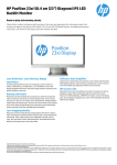
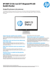
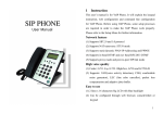
Uninterruptible Power Supply-UPS NST3 1KVA-6KVA USER MANUAL 1 1.Safety Instructions Please read the FOLLOWING user manual and the safety instructions before installing the unit and starting it up! 1.1 Transport ★ Please transport the UPS system only in the original packaging (to protect against shock and impact). 1.2 Set-up ★ Condensation may occur if the UPS system is moved directly from a cold to a warm environment. The UPS system must be absolutely dry before being installed. Please allow an acclimatization time of at least two hours. ★ Do not install the UPS system near water or in damp environments. ★ Do not install the UPS system where it would be exposed to direct sunlight or near heat. ★ Do not block off ventilation openings in the UPS system’s housing. 1.3 Installation ★ Do not connect appliances or items of equipment which would overload the UPS system (e.g. laser printers) to the UPS outlet socket ★ Place cables in such a way that no one can step on or trip over them. ★ Do not connect domestic appliances such as hair dryers to UPS output sockets. ★ The UPS can be operated by any individuals with no previous experience ★ Connect the UPS system only to an earthed shockproof socket outlet. ★ The building wiring socket outlet (shockproof socket outlet) must be easily accessible and close to the UPS system. ★ Please use only VDE-tested, CE-marked mains cable (e.g. the mains cable of your computer) to connect the UPS system to the building wiring socket outlet (shockproof socket outlet). ★ Please use only VDE-tested, CE-marked power cables to connect the loads to the UPS system. ★ This is operator installable. ★ When installing the equipment, it should ensure that the sum of the leakage current of the UPS and the connected consumer does not exceed 3.5mA. 2 1.4 Operation ★ Do not disconnect the mains cable on the UPS system or the building wiring socket outlet (shockproof socket outlet) during operations since this would cancel the protective earthing of the UPS system and of all connected loads. ★ The UPS system features its own, internal current source (batteries). The UPS output sockets or output terminals block may be electrically lived even if the UPS system is not connected to the building wiring socket outlet. ★ In order to fully disconnect the UPS system, first press the Standby switch then disconnect the mains lead ★ Ensure that no fluids or other foreign objects can enter the UPS system. ★ The UPS operates with hazardous voltages. Only qualified maintenance personnel may carry out repairs 1.5 Maintenance, servicing and faults ★ The UPS system operates with hazardous voltages. Repairs may be carried out only by qualified maintenance personnel. ★ Caution - risk of electric shock. Even after the unit is disconnected from the mains power supply (building wiring socket outlet), components inside the UPS system are still connected to the battery and are still electrically live and dangerous. ★ Before carrying out any kind of servicing and/or maintenance, disconnect the batteries and verify that no current is present and no hazardous voltage exist in the terminals of high capability capacitor such as BUScapacitors. ★ Only persons are adequately familiar with batteries and with the required precautionary measures may replace batteries and supervise operations. Unauthorised persons must be kept well away from the batteries. ★ Caution - risk of electric shock. The battery circuit is not isolated from the input voltage. Hazardous voltages may occur between the battery terminals and the ground. Before touching, please verify that no voltage is present! ★ Batteries may cause electric shock and have a high short-circuit current. Please take the precautionary measures specified below and any other measures necessary when working with batteries: remove wristwatches, rings and other metal objects use only tools with insulated grips and handles. ★ When changing batteries, install the same number and same type of batteries. ★ Do not attempt to dispose of batteries by burning them. This could cause battery explosion. ★ Do not open or destroy batteries. Escaping electrolyte can cause injury to the skin and eyes. It may be toxic. ★ Please replace the fuse only by a fuse of the same type and of the same amperage in order to avoid fire hazards. ★ Do not dismantle the UPS system. 3 2. Description of commonly used notations Some or all of the following Notations may be used in this manual and may appear in your application process. Therefore, all users should be familiar with them and understand their explanations. 4 3. Introduction This On-Line-Series is an uninterruptible power supply incorporating double-converter technology. It provides perfect protection specifically for Novell, Windows NT and UNIX servers. The double-converter principle eliminates all mains power disturbances. A rectifier converts the alternating current from the socket outlet to direct current. This direct current charges the batteries and powers the inverter. On the basis of this DC voltage, the inverter generates a sinusoidal AC voltage, which permanently supplies the loads. Computers and periphery are thus powered entirely by the mains voltage. In the event of power failure, the maintenance-free batteries power the inverter. This manual covers the UPS listed as follows. Please confirm whether it is the model you intend to purchase by performing a visual inspection of the Model No. on the rear panel of the UPS. Model No. Std Model No. Long back NST3100010 NST3100010-L NST3100020 NST3100020-L NST3100030 NST3100030-L NST3100050 NST3100050-L NST3100060 NST3100060-L Remark “L” Model: Long backup time 5 4. System Description Indicator 4 Load capacity LED Indicator 3 Indicator 2 Bat capacity LED Indicator 1 Fault mode LED Line mode LED Bat mode LED Bypass mode LED Multi-Function Switch ON – Switch OFF – Switch Figure 1: LED Display Panel Switch ON - Switch Function Turn on UPS system: By pressing the ON-Switch “I” the UPS system is turned on. OFF-Switch When mains power is normal, the UPS system switches to Standby mode by pressing OFF-Switch . It is then switched to Bypass and the inverter is off. At this moment, the output sockets are supplied with voltage via the bypass if the mains power is available. When UPS system turned on, touch this button, “Load capacity LED” and “Battery capacity LED” will shine by turns, then its capacity will be shown. Multi-Function Switch Display LINE mode LED Function The LINE mode LED lights up if mains voltage is applied to the UPS input. LINE mode LED blinks when the phase and neutral conductor have been reversed at the input of the UPS system. BAT mode LED BYPASS mode LED FAULT mode LED LOAD and BAT capacity LEDs The BAT mode LED lights up when the mains power has failed and the inverter is being powered by the batteries. The BYPASS mode LED lights up when the UPS system is supplying voltage provided by the mains power via the bypass. The FAULT mode LED lights up and an acoustic warning signal is issued continuously when the UPS system is in fault condition. These LEDs show the load of the UPS system if the LOAD capacity LED light up: 1st LED 0-25% 2nd LED 26-50% 3rd LED 51-75% 4th LED 76-100% These LEDs show the battery capacity of the UPS system if the BAT capacity LED light up 1st LED 0-25% 2nd LED 26-50% 3rd LED 51-75% 4th LED 76-100% 6 Fault mode LED Bat mode LED Line &Bypass mode LED LCD Display Figure 2: LED Display Panel LCD display details as following: Welcome WELCOME TO USE GREEN POWER OUTPUT 120Vac 60.0Hz System status SYSTEM STATUS LINE MODE Input characteristic Battery characteristic BATTERY 80.2V 100% Input characteristic INPUT 120 Vac 60 .0Hz Load and temperature LOAD 25% TEMP 25 ℃ Note: the Line mode LED and the Bypass mode LED is the same LED in LCD panel UPS. 7 5. Connection and Operation The system may be installed and wired only by qualified electricians in accordance with applicable safety regulations! 5.1 Connection and operation for 1K(L)1.5k(L)/ 2K(L)/ 3K(L) When installing the electrical wiring, please note the nominal amperage of your incoming feeder 1) Inspection: Inspect the packaging carton and its contents for damage. Please inform the transport agency immediately should you find signs of damage. Please keep the packaging in a safe place for future use. Note: Please ensure that the incoming feeder is isolated and secured to prevent it from being switched back on again. 2) Connection: 2.1) UPS Input Connection If the UPS is connected via the power cord, please use a proper socket with protection against electric current, and pay attention to the capacity of the socket: over 15A for 1~3K. 2.2) UPS Output Connection Simply plug the load power cord to the output sockets to complete connection. Model No. NST3100010 Output Socket (pcs) 2 Terminal Block Nil NST3100020 3+1high current output Nil NST3100030 3+1high current output Nil NST3100050-L 0 1 NST3100060 0 1 2.3) Computer Connection: Connect your computer to the outlet sockets of the UPS system following the above diagram. Caution! *Do not connect equipment which would overload the UPS system (e.g. laser printers) 8 3) Battery Charge: Fully charge the batteries of the UPS system by leaving the UPS system connected to the mains for 1-2 hours. You may use the UPS system directly without charging it but the stored energy time may be shorter than the nominal value specified. 4) Turn On the UPS: 4.1) With utility power connecting: Connect the utility power UPS will get into the Bypass mode, the Bypass mode LED will light up. Press “ON” button continuously for more than 1 second to turn on the UPS. Then the UPS will get into self-test status first. After having finishing the self-test, the UPS will get into the inverter mode, at this time, the LINE mode LED will light up. 4.2) Without utility power connecting: Even though utility power is not connected to the UPS, the UPS still can be turned on by just simply pressing “ON” button continuously for more than 1 second. Then the UPS will get into selftest status first. After having finishing the self-test, the UPS will get into the inverter mode, at this time, Battery mode LED, will light up. 5) Test Function: Test the function of the UPS system by either pressing the On-Switch or disconnecting the input of the UPS system from the power supply. 6) Turn Off the UPS: 6.1) In Inverter Mode: Press “OFF“ button continuously for more than 1 second to turn off the UPS. Then the UPS will get into self-test status first. After having finished the self-test, the UPS will get into bypass mode and Bypass mode LED will light up. At this time, the UPS might has output. Disconnect the utility power to turn off the output. 6.2) In Battery Mode: Press “OFF“ button continuously for more than 1 second to turn off the UPS. Then the UPS will get into self-test status first. After having finished the self-test, the UPS will be turned off completely. 7) Audible Alarm Mute Function: If the alarm is too annoying in battery mode, you may press “ON” button continuously for more than 1 second to clear it. Moreover, the alarm will be enabled when the battery is low to remind you to shutdown the load soon. 9 8) Operation Procedure of External Battery for Long Backup time Model (“L” Model) (1) Use the battery pack with right voltage. Connection of batteries more than or less than required will cause abnormality (2) One end of the external battery cord is a plug for connecting the UPS and the other end has a plug for connecting the user battery cabinet (3) Do not connect the UPS to any load yet. Then, connect the power cord of the UPS to supply utility power to the UPS to make the UPS operate in utility power mode. (4) Connect the plug of the external battery cord to the external battery socket on the rear panel of the UPS to complete the connection procedure and the UPS will start to charge the battery pack. 6. Maintenance 6.1 Operation The UPS system contains no user-serviceable parts. If the battery service life (3 - 5 years at 25°C ambient temperature) has been exceeded, the batteries must be replaced. In this case please contact your dealer. 6.2 Storage If the batteries are stored in temperate climatic zones, they should be charged every three months for 1-2 hours. You should shorten the charging intervals to two months at locations subject to high temperatures. 10 7. Technical Data 7.1 Electrical specifications INPUT Model No. Phase Frequency 1KVA 2KVA 3KVA Single 50/60Hz 5KVA 6KVA OUTPUT Model No. Power rating Voltage Frequency Wave form 1KVA 2KVA 3KVA 5KVA 6KVA 1kVA/0.8kW 2kVA/1.6kW 3kVA/2.4kW 5KVA/4KW 6KVA/4.8KW 220/230/240×1-2%VAC OR 110/115/120×1220/230/240×1-2%VAC 2%VAC 50/60×1±0.3%Hz (Battery mode) sinusoidal BATTERIES Model No. Number and type 1KVA 2KVA 3KVA 3×12V 7/9Ah 6×12V 7/9Ah 8×12V 7/9Ah 5KVA 10×12V 9Ah 6KVA 20×12V 7/9Ah 7.2 Operating Environment Ambient Temperature Operating humidity Altitude Storage temperature 0 oC to 40 oC < 95% < 7000Feet 0 oC ~ 40 oC 7.3 Dimensions and weights Model No. 1KVA Dimensions W x D x H (mm) 144X 420X215 Net Weight kg 16KG (3pcs batteries) 1KVA-L 2KVA 2KVA-L 144X 420X215 191X475X340 191X475X340 8 31KG (6pcs batteries) 18 3KVA 3KVA-L 5-6KVA-L 5KVA 6KVA 191X475X340 191X475X340 213 X 475 X 340 213 X 510 X 427 213 X 510 X 427 35KG (8pcs batteries) 18 18 45KG (10pcs batteries) 70KG (20pcs batteries) 11 the following standards: EN62040-1-1 (safety) Conducted Emission: EN50091-2..............................................................Class B Radiated Emission: EN50091-2.................................................................Class B Harmonic Current: EN61000-3-2 Voltage Fluctuations and Flicker: EN61000-3-3 EMS: EN61000-4-2(ESD)...........................................................................Level 4 EN61000-4-3(RS) ......................................................................................Level 3 EN61000-4-4(EFT).....................................................................................Level 4 EN61000-4-5(lighting surge).......................................................................Level 4 EN61000-2-2 (Immunity to low frequency signals) 12 9. Communication Port 9.1 RS232 Interface The following is the pin assignment and description of DB-9 connector. Pin # 2 3 5 Description TXD RXD GND I/O Output Input Input 9.2 AS400 Interface(Option) Except for the communication protocol as mentioned above, this series UPS has AS400 card (an optional accessory) for AS400 communication protocol . Please contact your local distributor for details. The following is the pin assignment and description of DB-9 connector in AS400 card. Pin # 1 2 Description I/O UPS Fail Summary Alarm Output Output 3 GND Input 4 Input 5 Remote Shutdown Common 6 Bypass Output 7 Battery Low Output 8 UPS ON Output 9 Line Loss Output Input Figure 16.2: DB-9 Interface of AS400 communication protocol 10. Appendix 1 The Corresponding Form of the LED Display for 1-3K No. state 25% 1 2 Load Capacity 0 ~25 26 ~50 3 51 ~75 4 76 ~100 5 6 7 Battery capacity 0 ~25 26 ~50 8 51 ~75 9 76 ~100 10 11 12 Bypass Mode ● ● ● ● ● ● ● 75% ● ● 100 % ● LED Display load bat ● ● ● ● ● ● ● ● ● ● ● ● ● ● ● ● ↑ ● ↑ ● ↑ ● ↑ ★ ● ● ● ● ★ ● ● ↑ ● ↑ ● ↑ ● ↑ ★ 14 Overload in line mode, change to Bypass Overload in line mode, Not change to bypass Line Fault 15 Overload in bat mode 16 Overload in bat mode 17 Over-temperature 18 Inverter abnormal 19 BUS voltage anomalies 20 Charging-V is too high 21 Bat-V abnormal 22 Line L and N changed 23 Charging Board or battery Fault 24 O/P short ● ● ● ● 25 Fan Fault ● 13 50% ● ● ● ● Buzzer line bps bat ↑ ↑ ↑ ↑ ↑ ↑ ↑ ↑ ↑ ↑ ↑ ↑ No sound ↑ ↑ ↑ ↑ ↑ ↑ ↑ ↑ ↑ ↑ ↑ ↑ Buzzing every 1sec ↑ ↑ ★ ● ● ● ↑ ↑ ↑ No sound Buzzing every 4sec Buzzing every 4sec Buzzing every 4sec ● ↑ ↑ ● ● ● ↑ ↑ ↑ No sound ● ● ↑ ↑ ↑ No sound Buzzing every 2min ● ● ★ ↑ ↑ ↑ ● fault ↑ ↑ ↑ ↑ ★ ↑ ↑ ↑ ● ↑ ● ↑ ● ↑ ● ↑ ★ Buzzing continuously Buzzing every 0.5sec ↑ Buzzing every 0.5sec Buzzing continuously Buzzing continuously Buzzing continuously Buzzing continuously Buzzing continuously ↑ Buzzing every 2min ↑ ↑ ★ ↑ ●: Solid ON ★ : Flash ↑ : LED display and alarm warning are dependent on other conditions. ● ● ● Buzzing every 1sec Buzzing continuously Buzzing every 1sec