1
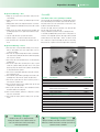
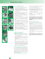
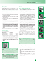
MANTIS
Welcome
We l c o m e t o t h e w o r l d o f
Mantis Gardening
ere’s your new Mantis Tiller/Cultivator
H
…the lightweight wonder that “Changes
Gardening Forever“. Unlike big tillers, your
Mantis Tiller weighs just 20 lbs. (9 kilos) so it lifts
easily, handles smoothly, tills and weeds precisely.
Unlike other small tillers, it features serpentine tines
that churn soil to ten inches (25 cm) deep. It creates a soft seed bed, even in problem soil. Once
you know how to use your tiller correctly, we guarantee you’ll depend on it.
So first, please read this manual. It shows, step
by step, how to use your tiller safely. If you have
questions about any topic in this Manual, or if you
wish to order Mantis attachments, contact us at
Mantis.
MANTIS
Table of contents
Table of contents
Safety rules & warnings .......................................................................................................................................................... 27
Engine/Fuel ........................................................................................................................................................................... 29
Assembly ............................................................................................................................................................................... 29
Mixing Fuel ............................................................................................................................................................................ 31
Starting ................................................................................................................................................................................. 31
Stop the Eninge ...................................................................................................................................................................... 32
What to do ............................................................................................................................................................................ 32
Transport ............................................................................................................................................................................... 33
Tilling ..................................................................................................................................................................................... 33
Weeding ................................................................................................................................................................................ 34
Maintenance .......................................................................................................................................................................... 35
Trouble Shooting ..................................................................................................................................................................... 36
Storage ................................................................................................................................................................................. 37
Engine specifications .............................................................................................................................................................. 38
Service maintenance guide ..................................................................................................................................................... 38
Trouble Shooting .................................................................................................................................................................... 39
Spare Parts............................................................................................................................................................................. 40
The Mantis promise ............................................................................................................................................................... 44
Limited warranty information for Mantis tiller ........................................................................................................................... 44
Repair or refund Form ............................................................................................................................................................. 45
EC Declaration of conformity.................................................................................................................................................... 90
Noise emission ....................................................................................................................................................................... 91
Table
of contents
Safety rules & warnings
MANTIS
Safety rules
& warnings
UK
You will notice throughout this owners manual safety rules and important notes.
Please, make sure you understand and obey these warnings for your own protection.
Safety & Warnings
!
Special Safety Information
!
Warning • Danger
Warning • Danger
!
Improper use or care of this Tiller/Cultivator or failure to wear
proper protection can result in serious injury.
Read and understand the rules for safe operation and all instructions
in this manual. Wear hearing and eye protection.
!
Attention: This symbol points out our important safety Instructions.
When you see this symbol, heed it’s warning!! Stay alert!!
Safety Decal Information
!
Warning • Danger
!
To reduce the potnetial for accidents, comply with the safety Instructions
in this Manual. Failure to comply may result in serious personal injury,
and/or equipment and property damage.
!
Warning • Danger
!
If the Tiller is used improperly or safety precautions are not followed the
users risk serious injury to themselves and others. Read and understand
this manual before attempting to operate this Tiller.
An important part of the safety system incorporated into this tiller are the warning and
information decals found on various parts of the tiller. These decals must be replaced
in time due to abrasion, etc. It is your responsibility to replace these decals when they
become hard to read. The location and part numbers (P/N) of these decals are illustrated on Page 18.
27
MANTIS
Safety rules & warnings
Warnings – Don’ts
Warnings – Don'ts
Read and understand the owner’s manual. Pay particular
attention to all sections regarding safety.
P/N 488M
1. Always keep a firm grip on both handles while the tines are
moving and/or the engine is running. Be aware!! The tines may
coast after throttle trigger is released. Make sure tines have
come to a complete stop and engine is off before letting go of
the tiller.
2. Always maintain a firm footing and good balance. Do not overreach while operating the tiller. Before you start to use the tiller
check the work area for obstacles that might cause you to lose
your footing, balance or control of the machine.
3. Thoroughly inspect the area where equipment is to be used
and remove all objects, which can be thrown by the machine.
4. Always keep area clear of children, pets, and bystanders.
5. Always stay alert. Watch what you are doing and use common
sense. Do not operate unit when fatigued.
6. Always dress properly. Do not wear loose clothing or jewellery
as they might get caught in moving parts. Use sturdy gloves.
Gloves reduce the transmission of vibration to your hands.
Prolonged exposure to vibration can cause numbness and
other ailments. Wear non-skid foot wear to ensure secure and
proper footing.
7. While working, always wear substantial footwear and long
trousers. Do not operate the equipment when barefoot or
wearing open sandals.
8. Always wear ear and eye protection. Eye protection must meet
applicable CE requirements. To avoid hearing damage, we recommend hearing protection be worn whenever using the
equipment.
9. To reduce fire hazard, keep the engine, and petrol/gas storage
area free of vegetative material and excessive grease.
10. Start the engine carefully, according to the manufacturer’s
instructions and with feet well away from tool(s).
11. Keep all nuts, bolts and screws tight to be sure the equipment
is in safe working condition.
12. Use extreme caution when reversing or pulling the machine
towards you.
13. Work only in daylight or good artificial light.
14. Always be sure of your footing on slopes
15. Exercise extreme caution when changing direction on slopes.
16. Always keep a safe distance between two or more people
when working together.
17. Always inspect your unit before each use and ensure that all
handles, guards and fasteners are secure, operating, and in
place.
18. Always maintain and examine your Tiller with care. Follow
maintenance instructions given in manual.
19. Always store tiller in a sheltered area (a dry place), not accessible to children. The tiller as well as fuel should not be stored
in a house.
P/N 4043
Don’t fuel, refuel, or
check fuel while smoking, or near an open
flame or other ignition
source.
Mix unleadeD petrol with
2 stroke oil, 50:1 ratio.
Incorrect assembly.
Caution: when assembling the handles, make
sure fuel tank faces
operator.This is the rear
of the tiller, refer to
assembly instruction on page 30.
Cutting hazard: keep feet
and hands away from
rotating tines.
Wear ear and eye protection.
Read owners manual
before using tiller, or
performing any repair
or maintenance. Keep
owners manual in a safe
place.
Do not carry the tiller in
this position.
28
1. Don’t use tiller with one hand. Keep both hands on handles with
fingers and thumbs encircling the handles, while tines are moving, and engine is running.
2. Don’t overreach. Keep a good footing at all times.
3. Don’t run with the machine, walk.
4. Don’t work on excessively steep slopes.
5. Don’t attempt to clear tines while they are moving. Never try to
remove jammed material before switching the engine off and
making sure the tines have stopped completely.
6. Don’t allow children or incapable people to operate this tiller.
7. Don’t operate while under the influence of alcohol or drugs.
8. Don’t attempt to repair this tiller. Have repairs made by a qualified repairman or Mantis. See that only original Mantis parts are
used.
Engine/Fuel – Assembly
Engine/Fuel Warnings – Do’s
1. Always use fresh petrol in the fuel mixture. Stale petrol can
cause damage.
2. Always store fuel in containers specifically designed for this
purpose.
3. Always pull the starter cord slowly until resistance is felt. Then
pull cord rapidly to avoid kickback and to prevent arm or hand
injury.
4. Always operate the engine with spark arrestor installed and
operating properly. The use of spark arrestor mufflers is required by law.
5. Stop the engine whenever you leave the machine.
6. Allow the engine to cool before storing in any enclosure.
7. If the fuel tank needs to be drained, this should be done outdoors.
Engine/Fuel Warnings - Don’ts
1. Don’t fuel, refuel or check fuel while smoking, or near an open
flame or other ignition source. Stop engine and be sure it is
cool before refueling.
2. Don’t leave the engine running while the tiller is unattended.
Stop engine before putting the tiller down or while transporting
from one place to another.
3. Don’t refuel, start or run this tiller indoors or in an improperly
ventilated area.
4. Don’t run the engine when electrical system causes a spark
outside the cylinder. During periodical checks of the spark
plug, keep plug a safe distance from cylinder to avoid burning
of evaporated fuel from cylinder.
5. Don’t check for spark with spark plug or plug wire removed.
Use an approved tester.
6. Don’t crank the engine with the spark plug removed unless the
spark plug wire is disconnected. Sparks can ignite fumes.
7. Don’t run the engine when the odour of petrol is present or
other explosive conditions exist.
8. Don’t operate the unit if petrol is spilled. Clean up the spill
completely before starting engine.
9. Don’t operate your tiller if there is an accumulation of debris
around the muffler, and cooling fins.
10. Don’t touch hot mufflers, cylinders or cooling fins as contact
may cause serious burns.
11. Don’t change the engine governor setting or over speed the
engine.
!
Warning • Danger
Handle fuel with care, it is highly flammable.
Fueling a hot engine or near an ignition source can
cause a fire and result in serious personal injury
and/or property damage.
MANTIS
Assembly
Your Mantis Tiller comes partially assembled
You must install only the handlebars, the carrying handle, and the
tines. This will take just a few minutes if you follow the directions.
First, take all items out of the carton but do not remove the cardboard from around the Tiller’s base.
The list at the right, shows the parts that come with your tiller.
Check to make sure you have them all.
The bag of hardware is packed in the box containing the tines.
To assemble your Mantis Tiller, you’ll need two 11 mm spanners or
wrenches or two adjustable spanners. We suggest that you install
all nuts and bolts only “finger tight” – that is, one-half to one full
turn – until you’ve completed assembly. The nuts are self locking,
but you must use a spanner or wrench to tighten them completely.
Key-No.
4A
5A
6
39/40
20, 21, 55
8
42
47
48
49
41
51
13
52
53
Description
Upper Handle Assembly
Upper Handle Throttle Side Assembly
Lower Handles
Pair Tiller/Cultivator Tines
Engine Assembly (includes Fender
Guard & Worm-Gear Transmission)
Handle Brace
Plastic Carrying Handle
Bag of Hardware Containing:
Cap Screws
Lock Nuts
Bolts (3” long)
Tine Retaining Pins
Handle Clamps
Throttle Clip
Bolts
Knobs
UK
Qty
1
1
2
1
1
1
1
Article-No
400236
400235
400224
438LA / 438RA
400903/465/
400010
148
400218
2
4
2
2
2
1
2
2
410
972
470
418-1
377
478
400509
400510
!
!
Warning • Danger
!
Improper assembly of this Tiller can result in serious injury.
Make sure to follow all instructions carefully. If you have any
questions contact us at Mantis.
29
MANTIS
Assembly of handles – Tilling Tines
1
7
2
8
3
9
4
10
How to assemble lower handles
1. Use the protective cardboard sleeve to stabilize your
tiller. Stand the engine assembly (#21) up.
2. Lay the handle parts within easy reach. You’ll need one
of the handle clamps (#51) and one of the lower handles (#6). Note that the lower handles have a short leg
on one end (Picture 1.
3. Fit the handle clamp along the outside of the short leg.
Line up the holes on the clamp and the leg.
4. Choose one of the two 3-inch bolts (Nr. 49). Slide it
through the first set of holes – near the elbow where the
lower handle curves (Picture 2).
5. Now slide the other lower handle onto the 3-inch bolt
(Picture 3). Fit the other clamp onto this other handle’s
short leg. Add a self-threading nut and tighten finger
tight.
6. Locate the worm-gear housing. It starts just above and
extends down through the tiller’s red fender guard.
You’ll notice that there’s a recessed channel on either
side of the housing’s top (Picture 4).
7. Take the lower handles that you’ve just put together.
Slide them into the two recessed channels.
Make sure you insert them from the rear of the tiller
(petrol tank faces the operator) …so that the bolt fits
along the back of the housing (Picture 5).
8. Slide the second 3-inch bolt through the second set of
holes in the short legs. Add a nut and tighten finger
tight.
How to assemble upper handles
and plastic carrying handle
1. Lightly squeeze the lower handles (#6) toward one
another so that they line up with the two smaller holes
on the carrying handle (#42).
Then slide the carrying handle over and down the lower
handles. It will rest about four to six inches above the
engine (Picture 6).
2. Gently pull the lower handles out to their original position.
3. Attach the upper handle assembly (#5A) - the handle
with the throttle cable and ground wire - onto either
lower handle, and secure with the handle knob (#53).
You can attach this upper handle to whichever lower
handle you prefer, depending on which hand you’d
rather use to squeeze the throttle (Picture 7).
(Note: If throttle handle is mounted on the left, it will not fold
down as completely as when mounted on the right).
Be sure you have proper throttle movements and that the
throttle cable is not wrapped or twisted around the handle
bar. Squeeze trigger and let go. The triangle must click in
both directions. If there is any doubt, remove air filter and
visually check that the throttle triangle hits both the idle
screw and the full open stop.
THIS MUST BE DONE BEFORE STARTING THE ENGINE.
5
6
30
4. Follow the same steps to install the other upper handle
onto the other lower handle (Picture 7).
5. Use the clip (#13) to secure the throttle cable and wire
in place on the lower handle (Picture 8).
6. Now install the Handle Brace. Line it up with the holes
on the upper handles. Then insert a Cap Screw and a
Lock Nut on either side (Picture 9).
7. Use a spanner or wrench to tighten Cap Screws and
Lock Nuts.
8. Now use spanner or wrench to tighten ALL nuts and
bolts firmly and securely.
☞ Important Note: Make sure you have installed the
handles properly. When you stand behind your
tiller, holding the handles, you should face the
petrol tank.
Assembling the Tines for Tilling
1. Remove the cardboard from around your Tiller’s base.
2. Slide the tines onto the axle shafts. The “D” hole goes
on the outside.
3. Make sure you’ve installed the tines properly for tilling.
Liken the tines to your fingers. When your palm faces
the ground, your fingers curl down. Stand behind the
Tiller and hold your hand next to the tines. Do the tine
blades curl down, as your fingers do? If so, they are in
the tilling/cultivating position. (To switch to the weeding
position, see page 34.)
4. To secure each tine to the axle, insert a tine retaining
pin (Picture 10).
☞ Important Note: Before you use your Mantis Tiller,
read the Safety Rules & Warnings on pages 27 to
28.
Sicherheitsvorschriften
Mixingund
Fuel
Warnungen
– Starting
Mixing Fuel
Starting
Your Mantis Tiller is powered by a commercial two stroke, air cooled
engine which requires a fuel mixture of unleaded petrol and lubricating oil.
Use a mixture of 50 parts unleaded regular petrol and 1 part twostroke Mantis oil (50:1).
To Start Your Tiller for the First Time
1. Fill the fuel tank with the proper oil/unleaded petrol mixture.
(See previous section.)
2. Hand tighten the petrol cap just until it’s snug.
3. Place the start/stop switch into the “start” position (Picture 1).
4. Pull out the choke button to close the engine choke (Picture 2).
5. Locate the purge bulb on the upper right of the engine, in front
of the fuel tank (Picture 3). It sends fuel into the carburettor, for
easy starting. Press the purge bulb until you see fuel flow
through the clear fuel return line. Since you’re starting “cold,”
you may need to press six to eight times. As soon as fuel starts
flowing through the clear fuel line, stop pressing!
6. Don’t press the throttle lever during the starting of the engine.
7. Pull the starter cord (Picture 4) slowly until resistance is felt.
Then give the recoil starter cord a few short, brisk pulls until the
engine fires. During cold starting, you may need to pull at least
three or four times before the engine fires.
☞ Important Note: When the choke is closed, never pull the
cord more than four or five times. Overpulling may cause
flooding. Also, bear in mind that, when the engine fires, it
only coughs or sputters, and will not run on choke.
8. Push in the choke button to open the choke (Picture 5).
9. Then pull the starter cord again using short sharp pulls. The
engine should start and run. Let the engine warm up two to
three minutes before using.
Follow these steps whenever you are starting the engine “cold”, or
when the engine has run dry and you have just added fuel.
Remember, always use short, brisk pulls. Don’t give the cord a long,
forceful yank. And, do not let the cord snap back into the starter
housing.
How to mix the oil and petrol
1. Pour 1/2 of the petrol into a safe container. Do not mix the fuel
and oil in the engine fuel tank.
2. Add the two-stroke engine oil to the petrol and mix. Then add
the rest of the petrol.
3. Screw the cap onto the petrol can. Then swirl the can to blend
the oil and petrol.
4. Carefully pour the fuel mix into the tiller’s fuel tank. After putting
the fuel tank’s cap back on, wipe up any spilled fuel from tank
and petrol can.
☞ Important Note: Two stroke fuel separates and ages. Do
not mix more than you will use in a month. Using old fuel
can cause difficult starting or engine damage. Shake fuel
container to thoroughly mix fuel before each use. Do not
attempt to run your engine on petrol only - use proper fuel
mixture.
Should you need pre-measured engine oil, please, contact Mantis.
Fuel Mixture Guide
Use 2% oil Mix (50:1 Ratio)
Unleaded Petrol
black Mantis Oil bottles:
white Mantis Oil bottles:
2-Stroke Oil
5 Liter Petrol
4 Liter Petrol
100 ml Öl
80 ml Öl
MMAANNTTI S
IS
1
UK
2
3
4
☞ Important Note: Do not use old or stale oil/petrol mixture
and always use the proper oil/petrol mixture. If you do
not, your engine will suffer rapid, permanent damage and
you will void the engine warranty. Never run your tiller on
petrol alone; it will ruin the engine and void all warranties.
!
Warning • Danger
!
Fuel is extremely flammable. Handle it with care.
Keep away from ignition sources.
Do not smoke while fueling your equipment.
!
Warning • Danger
!
Avoid accidental blade engagement. Do not squeeze the
throttle trigger when starting. Maintain proper idle speed
adjustment (2500–3100 RPM).
5
!
Warning • Danger
!
Never use starting fluids as they will cause permanent
engine damage. Using them will void the warranty.
Before you use the tiller, read the Safety & Warning rules
on pages 27–28.
Starting a Warm Engine
1. Slide the ignition switch to START position.
2. Push the choke button into the RUN (open) position.
3. If there is no fuel in the clear return line, push the primer bulb
3–4 times or until fuel is visible in the line.
4. Pull the starter rope using short pulls, 1/2 to 2/3 of the rope
length.
5. If the engine fails to start in 4 pulls, use “First Time” starting procedure.
6. With the engine running, and both hands on the handles,
squeeze throttle trigger gradually to increase the engine speed
and engage the tines.
31
MANTIS
Stop the Engine – What to do…
Additional information
How to Stop the Engine
Simply push the start/stop switch to “stop” (Picture 1). This will stop
the engine instantly. If it should ever fail to do so, just pull out the
choke button. The engine will stop at once.
1
About the Choke
The choke controls the amount of air drawn into the engine. Your
tiller will run only if the choke is open – that is, if the choke is
pushed in.
A Special Feature (with the idle set properly and
the engine running)
Even when the engine is running, the tines won’t turn unless you
press the throttle lever on the handlebars. And, when you release
the throttle lever, the tines will stop.
A Tip for Extending Your Engine’s Life
After you start the engine, let your tiller warm up for two to three
minutes before you use it. Then, before you put your tiller away, let
it idle for a minute to give the engine a chance to cool down.
What to do just in case the
engine will not start
If you follow the normal starting procedure, you should have no
problem starting your tiller. But, just in case you do have problems,
here’s what to do.
Make sure the start/stop switch is on “start.” You’d be surprised
how many people forget to push the switch into the “start” position.
If the switch was on “stop” when you pulled the cord, you may have
flooded the engine.
– First, examine the spark plug. Use a 3/4 inch (19 mm) spark
plug wrench (Picture 2).
– Remove the cap over the spark plug.
☞ Important Note: To avoid possible damage to the threads,
do not try to remove the plug from a hot aluminum cylinder head.
– Unscrew the spark plug (Picture 3).
2
3
Starting a Flooded Engine
1. If the end of the spark plug is wet, the engine may be flooded.
Make sure the switch is in the stop position, disconnect the
spark plug wire and remove the plug. Use a paper towel or a
clean rag to dry the spark plug, then, with the spark plug out of
the engine, pull the starter cord several times. Shake the fuel
out of the inside of the plug and air dry. Next, replace the spark
plug. Use the spanner or wrench to tighten it and replace the
cap. Next, put the switch in the start position and pull the choke
button out. Pull the starter cord three or four times until the
engine coughs or sputters. Open the choke (push the choke
button in) and pull the cord a few times. The engine should start
and run.
2. If the end of the spark plug is dry, check to see if the fuel line is
blocked. The fuel line runs from the fuel tank to the carburettor.
Pull it off at the carburettor end. Fuel should drip slowly from the
line. Wipe off any excess or spilled fuel. If fuel does not drip from
the line, check the line for any bends or pinches. (Picture 4).
Kinks in the line restrict the flow of fuel to the engine. Just
straighten out the line. Reconnect, then follow the normal starting procedure. If fuel drips too freely, the line may be disconnected from the fuel filter. You’ll find the fuel filter inside the fuel
tank. Just reattach the line to the filter, and put the filter back in
the tank. Then follow the normal starting procedure.
Here’s Another Way to Start your Mantis Tiller
If you follow the steps above and your engine still won’t start, try
this:
1. Push the switch to “start”.
2. Push in the choke button to open the choke.
3. Press the plastic bubble a few times.
4. Give the starter cord a few short, quick pulls. The engine should
start and run.
5. If the engine does not start, then pull out the choke button to
close the choke. Pull the starter cord four to five times. The
engine should sputter or cough.
6. After the engine sputters, push the choke button in. Then pull
the starter cord. The engine should start and run.
7. If the engine still does not start, repeat steps 2 to 6.
8. If the engine still does not start, contact our Service Department
at Mantis.
☞ Important Note: Never use starting fluids. Starting fluids
will cause permanent engine damage. Using them will
void the warranty.
4
☞ Important Note: Before you use your Mantis Tiller, read
the Safety Rules & Warnings on pages 27–28.
!
Warning • Danger
!
If Engine does not stop when switch is put in the stop
position, release the throttle, allow engine to idle.
Put the Tiller down, and pull the chocke button
out to cold start (closed) position. Check and return ignition
switch to on position before starting eninge again.
32
Transport – Tilling
Getting your tiller
to your garden
MANTIS
Tilling
Walk it
Once your tiller is running, you can “walk” it to your garden. Just
press the throttle lever gently and let the tiller “tip-toe” slowly
accross your yard on its tines. It won’t hurt your lawn or driveway
(Picture 1).
Carry It
Make sure the engine is off. Then use one hand to grasp the convenient carrying handle, and use the other hand to hold the handlebars (Picture 2). Then lift your tiller and carry it to your garden.
Since it weighs only 20 lb./9 kg, it won’t strain your muscles or tire
you out!
Take It for a Ride
You can easily transport your Mantis Tiller to a friend’s or relative’s
house. Just empty the fuel tank (this is crucial), then stow your Tiller
in the boot of your car or truck. You can put it in and take it out without straining your back.
Now You’re Ready to Use Your Mantis Tiller
If you’ve seen other tillers, your Mantis Tiller may surprise you. It
tills best when you pull it backward! You see, when you pull your
Mantis Tiller backward, you give extra resistance to the tines, so
they dig deeper (Picture 4).
What’s more, when you go backward you erase your footprints so
your soil stays light and fluffy. With other tillers, by contrast, you
walk right over the soil you’ve just tilled, packing it down so it’s less
plantable.
1
UK
Run Your Mantis Tiller like a Vacuum Cleaner
Place your Tiller at the head of the row or area you want to till. Start
it up. Then use an easy rocking motion. First, pull your Tiller backward. Then using an easy rocking motion, pull your Tiller backward.
Then, let it move forward just a little bit, and pull it backward again.
This will help you to till deeper.
Keep repeating these steps until you’ve tilled an entire row. Start
again on the next row, it’s much like running a vacuum cleaner
(Picture 5)! You can even control depth.
2
For Deeper Tilling/Cultivating
Move your Tiller slowly back and forth, as you would a vacuum
cleaner. Work the same area over and over until you’ve dug to your
desired depth.
3
For Shallow Tilling
Switch the tines to the weeding position. (See page 34 to learn
how.) Then move your Tiller quickly over your soil surface.
For Big Weeds or Tough Roots
Let your Tiller rock back and forth over the tough spot, until the
tines slice through the weed or root (Picture 5).
4
Your Mantis Tiller Handles Special Tilling Projects
Should you want to turn part of your lawn into a colourful flower
border your Mantis Tiller makes it easy! Just run your Tiller back
and forth until the ground begins to break up. Then continue tilling.
Your Tiller will chop the clumps of soil finely and work them into the
soil. Soon you’ll have a soft, fresh planting bed.
5
!
Warning • Danger
Never carry your Tiller as the person in
Picture 3 does. If you do the tines engage
and you could suffer serious injury.
!
!
Warning • Danger
!
The operator of this Tiller is responsible
for accidents or hazards occurring to himself,
other people or their property.
33
MANTIS
Weeding – Position of Tines
Weeding
Now your Mantis Tiller’s sharp “tine teeth” will slice up those annoying weeds, burying them as you go along. Since the tines in this
position won’t dig too deeply, they won’t hurt your plants’ precious
root systems.The result? Your Tiller will cut your weeding time in
half, and turn a tiresome chore into a pleasure.
1
How to Switch From the Tilling/Cultivating to the
Weeding Position
1. Make sure your Tiller/ Cultivator is turned off.
2. Remove the retaining pins from the tines.
3. Remove the tines from the axle.
4. Place the right-side tine onto the left-side axle. Place the left
side tine onto the right-side axle. The “D” hole should be to the
outside.
5. To ensure you’ve installed the tines properly, stand behind the
Tiller and hold your hand, palm up, next to the tines. Do the tine
points curl up, as your fingers do? If so, they are in the correct
weeding position.
6. Reinsert the retaining pins.
2
Tilling/Cultivating Position
Tine teeth point in the same direction as the rotation of the tine; or
toward the front of the Tiller, away from the operator.
Weeding Position
Tine teeth point in the opposite direction as the rotation of the tine.
Tines point toward the back of the tiller, or toward the operator.
Tilling/Cultivating
Position
Weeding Position
1
1
2
2
3
Weeding
4
Now You’re Ready to Weed.
Guide your Tiller where you want to weed and start it up. Pull your
Tiller backward slowly, then let it move forward a bit, in a gentle
rocking motion. Watch it slice, shred, and bury weeds!
If you have tough weeds lighten your pressure on the throttle to
slow your Tiller down. Then work back and forth until your Tiller
chops up the weeds. It’s easy and effective!
Remember, any tiller will tangle in tall grass, stringy vines, or tall
weeds. If you have a “backyard jungle,” first use a knife, pruner, or
brush cutter to chop up the overgrowth. If the tines become tangled
anyway, turn the engine off completely before trying to clear them.
!
Warning • Danger
!
If your Tines get jammed or entangled, shut off the
engine at once. Remove the obstruction while the Engine
is off. Never try to remove an obstruction while
the Engine is running. Serious injury can result.
34
3
hinten
1
2
3
4
vorne
Benzintank
Steuerholme
Drehung der Hackelemente
Zähne der Hackelemente
4
hinten
vorne
Maintenance – Trouble Shooting
Maintenance
Check the Air Filter Often
A wet or dirty air filter can affect the way your engine starts, performs, and wears so it’s a good idea to check your air filter once a
month. If you work in dusty soil, or if you want to be on the safe side
– check your filter more often (for instance, before each use). But
be sure to replace it at least once a year, in the spring or autumn.
How to Check, Clean and Change the Air Filter
1. Loosen the thumb screw on the side of the air-cleaner cover
(see Picture 1, or look up Key #1 in Air Cleaner Parts Assembly
on page 41).
2. Take off the cover. (Picture 2).
3. The air filter is the white pad on the inside of the air-cleaner
cover. Check whether it is soiled or moist.
4. If the air filter needs cleaning or no longer fits properly, remove
it. Just lift an edge carefully and “peel” it off (Picture 3).
5. Use a brush to remove debris from the pad.
6. If the air filter is so dirty that it won’t come clean, you must
replace it or severe engine damage will occur.
7. Insert your clean filter inside the air-cleaner cover. Note: Make
sure filter is “seated” properly in the housing. The filter must fit
snugly inside the rim of the air cleaner case. Installing the filter
incorrectly will cause engine damage and void the warranty. Fit
the cover back over the air cleaner.
☞ Important Note: Please check the lip on the Air Cleaner
Cover. If the lip is chipped or cracked, it should be
replaced. This will prevent dirt from being ingested
through the carburettor into the inside of the engine.
8. Tighten the thumb screw to secure the cover.
!
Warning • Danger
Remove tines before starting engine
and making adjustments.
!
MANTIS
How to Check the Grease Level
Inside the Worm-Gear Housing
When we built your Mantis Tiller, we lubricated the worm-gear
housing thoroughly. It is imperative that you inspect the grease level
at least once a year. Simply remove the cover plate on the wormgear housing (Picture 4). Then check to make sure the grease
comes almost to the top of the housing. If it doesn’t, add lithium
grease. This is the only way to add grease to the worm-gear housing (Picture 5). To purchase Mantis grease, please, contact us at
Mantis. Please do not overfill, too much grease can create pressure, which could cause seals to fail or the clutch to slip.
1
2
Clear Blockages From the Fuel Line & Filter
After you’ve used your Tiller for a few seasons, check for blockages
in the fuel tank and fuel filter. Such blockages can keep your Tiller
from starting. Clear any blockages you see in the tank, fuel filter, or
fuel line. Remember: The fuel filter is located inside the tank
(Picture 6). Then use the normal starting procedure to start your
Tiller.
3
What to Do if Your Engine Idles Too High
What if your engine runs too fast… or if the tines turn the instant
you start the Tiller? You may need to adjust the idle screw (#29
under Carburettor on page 41) by itself right below the H and L
screws. Gently turn it counter-clockwise. You’ll know you’ve adjusted it correctly when the axles do not turn at low idle.
If you continue to have idle problems, you may need to adjust the
throttle cable.
First, locate the metal triangle at the end of the throttle cable. The
idle screw must touch this triangle. But, if the throttle cable’s too
tight you’ll see a gap between the idle screw and the triangle.
To fix this, loosen the top nut that holds the throttle cable in place
(use an 11 mm spanner/ wrench or an adjustable wrench). Then
slide the cable down until you close the gap between the triangle
and the idle screw (Picture 7). Now, tighten the bottom nut that
holds the throttle cable.
Locate the metal “button” on the triangle. This is the swivel.
The large end of the throttle cable must be inside the slot in this
swivel.
4
5
6
7
35
UK
MANTIS
Maintenance – Trouble Shooting
What to Do if Your Engine Runs “Rough”
When we built your Mantis Tiller, we adjusted the carburettor for top
performance. But from time to time, it may need readjusting. If your
engine runs “rough” or stalls, the carburettor may be the cause.
1
1. Make sure the engine is shut off.
2. To identify the carburettor, look up Parts Assembly on page 41.
Then find the identical part on your Tiller.
3. If you remove the air-cleaner cover, you’ll see two letters
stamped on the carburettor body: “H” (on the left) and “L” (on the
right). They stand for “High-Speed Needle Valve” and “LowSpeed Needle Valve,” respectively (# 23 & 22 under Carburettor
on page 41). Lightly turn each screw clockwise until it’s completely closed (Picture 2).
4. Then, turn each screw counterclockwise very slowly — one full
turn plus one-quarter turn, more or less.
2
Every season, you may need to readjust the H and L screws to
ensure smooth running. You don’t need to take off the air-cleaner
cover. Just remove the tines and start the engine. While the engine
is at low idle, slowly turn the L screw counterclockwise, until the
engine sputters. Then slowly turn it clockwise until the engine
sounds smooth. Next, repeat the procedure for the H screw. But this
time, squeeze the throttle and run the engine at high speed. This
will make your Tiller run smoothly.
How to Reseat the Flange
(Clutch Case)
At some point, you may find that the tines won’t turn when you
press the throttle. This may mean the engine isn’t sitting all the way
down on the worm-gear housing.
Perhaps you’ve been using your Tiller for several years, or you’ve
removed the engine for use with our hedge trimmer attachment,
then replaced it. In either case, the flange bolt (#35, page 42) may
have come loose and lifted the engine up.
If this happens you’ll notice a gap between the bottom of the engine
flange (clutch case) (#36, page 42) and the top of the worm-gear
housing (Picture 3).
To fix this, loosen the flange bolt. Take the engine off the worm-gear
housing. Notice the hex head on top of the drive shaft. Inside the
flange housing, you will find the clutch drum (#30). Make sure the
hex head lines up with the clutch drum inside the flange housing.
Put the engine back on the worm-gear housing. Make sure the
plastic carrying handle is not under the fuel tank.
If you’ve followed these steps properly, there will be no gap
between the engine flange and the worm-gear housing (Picture 4).
Make sure you tighten the flange bolt!
3
4
36
Cleaning the Muffler Remove
Removing cylinder cover
1. Remove spark plug cap and spark plug.
2. Remove 2 screws (key# 33) and 1 bolt (key# 34).
3. Remove cylinder cover (key# 32).
Remove exhaust muffler
1. Remove 2 bolts (key# 24) and exhaust muffler (key# 21).
2. Cover exhaust port with piston to keep debris from entering the
engine.
Check inlet and tail pipe of exhaust muffler
1. Inspect exhaust muffler inlet, remove carbon deposits with
wooden or plastic stick.
2. Inspect tail pipe of exhaust muffler, remove carbon deposits with
small nylon brush.
☞ Important Note: This maintenance is recommended once
a month or every 90 hours of use. Reinstall exhaust
assembly and cylinder cover.
Storage
Storage
Each autumn – or before you store your Mantis Tiller for any long
period – be sure to take these measures:
1. Do not store your Tiller with fuel still in it. Even under ideal conditions, stored fuel containing ethanol or MTBE can start to go
stale in 30 days. Since stale fuel has a high gum content, it can
clog the carburettor. This, in turn, will restrict fuel flow. When
you’re ready to store your Tiller, or will not be using it for more
than 2 weeks, drain the fuel tank completely (Picture 1).
2. Next, restart the engine to make sure no fuel is left in the carburettor. Run the engine until it stops. This will prevent gum
deposits forming inside of the carburettor and possible engine
damage.
3. Disconnect the spark plug cap and remove the spark plug. Use
a 3/4 inch (19 mm) spark plug wrench. Pour about a teaspoon
of clean, two-stroke oil through the spark plug hole into the
combustion chamber (Picture 2). Slowly pull the starter cord
two or three times to coat the inside of the cylinder wall.
4. Inspect the spark plug and, if necessary, clean it. If you need
to replace it buy a NGK BPMR 7A or purchase one from
Mantis.
5. Install the spark plug, but leave the spark plug cap disconnected (Picture 3).
6. Clean the air filter as described on Page 10.
7. Clean dirt, grass, and other materials from the entire machine.
8. Wipe the tines with oil or spray them with WD-40, to prevent
rusting.
9. Oil the throttle cable and all visible moving parts (do not
remove the engine cover).
10. Check the grease level in the worm-gear housing, as
described on page 35.
11. Order new parts to replace any that are badly worn or broken,
just contact us at Mantis. But do it early, so you’ll have the
parts well before the next gardening season starts.
12. Store you Tiller – in an upright position – in a clean, dry place.
You can store with the handles in an extended position or folded down (Picture 4).
13. To fold the handles, follow these easy steps: Loosen the handle knobs (#53), fold the handles forward. Tighten knobs
securely. Your handles are now folded and ready to store in a
smaller area (Picture 5).
14. Do you have fuel left over from last season? Dispose of it properly. Buy fresh oil and unleaded petrol next season.
!
Warning • Danger
!
Do not store in an area where fuel fumes may accumulate
and reach a flame or spark.
MANTIS
How to Prepare Your Mantis Tiller for Restarting
Unfold the handles into an upright or extended position. Tighten the
two handle knobs (#53).
In the Spring, when you take your Tiller out of storage, remove the
spark plug. Pull the starter cord three or four times to clean oil from
the combustion chamber (Picture 4). Wipe oil from the spark plug.
Place the spark plug back into the cylinder. Re-connect the spark
plug wire onto the spark plug. Then follow the steps on page 31 to
refuel and restart your Tiller.
1
Again, Check the Carburettor
If your Tiller won’t restart in the Spring – or if it lacks its usual power
– the carburettor may need attention. Follow the steps on page 36
for adjusting the “H” and “L” screws (Picture 1 + 2).
UK
2
Check the Spark Plug Too
If your Tiller won’t restart, or if it lacks full power, the spark plug
may be at fault. Check to see if the plug is fouled with oily black
deposits. Clean or replace it if it is (Picture 3).
Also, check whether the center electrode is rounded at the end, or
if the ground electrode is worn. If either is the case, you should
replace it with a NGK BPMR 7A spark plug or purchase one from
Mantis. Use a 19 mm or a 3/4” spark plug spanner to install it.
Adjust the plug gap .024 - .028 in (0.6 to 0.7 mm).
Caution: Do not over tighten the plug.
3
☞ Important Note: To avoid possible damage to the threads,
do not try to remove the spark plug from a hot aluminum
cylinder head.
4
5
!
Warning • Danger
!
Always make sure the handle knobs are secure
before starting your Mantis tiller.
37
MANTIS
Engine Specifications – Service Maintenance Guide
Engine
specifications
Service
maintenance guide
38
Dry Weight
2.8 kg – 6 lbs., 3 ounces
Type of Engine
Air Cooled, Two-stroke, Single-Cylinder, Petrol Engine
Rotation
Clockwise, viewed from Top
Bore
32.2 mm (1.268 in.)
Stroke
26.0 mm (1.04 in.)
Spark Plug
NGK - BPMR 7A
Fuel
Premixed two-stroke fuel
Fuel Oil Ratio
50:1 ratio with Mantis oil (2% oil)
Petrol
Unleaded (see page 66)
Displacement
21.2 cc (1.294 cu. in.)
Exhaust System
Spark arrester muffler
Carburettor
ZAMA diaphragm model C1U type
Ignition System
Flywheel magneto, capacitor discharge ignition type
Starter
Automatic rewind type
Oil
Designated, two-stroke, air-cooled engine oil
Fuel Tank Capacity
.5 litre (17.0 oz.)
Area
Maintenance
Page
Frequency
Air Filter
Clean / Replace
35
Before Use
Fuel Filter
Inspect / Replace
35
Monthly
Spark Plug
Inspect / Clean / Adjust / Replace
32
Monthly
Carburettor
Adjust
36
Yearly
Cooling System
Inspect / Clean
–
Before Use
Muffler (Spark Arrestor)
Inspect / Clean
36
Monthly
Gear Housing
Check Grease
35
Yearly
Blades
Inspect / Clean / Lubricate
37
After Use
Fuel Leaks
Inspect / Repair
31
Before Use
Fasteners
Inspect / Tighten / Replace
30
Before Use
Labels
Inspect / Replace
28 + 40
Before Use
Handles
Inspect / Replace
40
Before Use
Guards / Safety Devices
Inspect / Replace
28
Before Use
Fuel Line
Inspect / Replace
32
Monthly
Starter Rope
Inspect / Replace
–
Monthly
Important:
Time Intervals shown are maximum. Actual use and your experience will determine the
frequency of required maintenance.
Trouble Shooting
MANTIS
Trouble Shooting
Problem
Cause
Remedy
1. Tines don’t turn when throttle
is depressed
– Engine is not seated properly on the gear housing.
– Re-install engine following the instructions
2. Engine fails to start
–
–
–
–
–
–
3. Engine hard to start
Page
36
Start/Stop switch is in Stop position.
No fuel in tank.
Fuel filter clogged.
Fuel line clogged.
Spark plug shorted or fouled.
Spark plug is broken
(cracked porcelain or electrodes broken)
– Ignition lead wire shorted,
broken or disconnected from spark plug.
– Ignition inoperative
– Diaphragm clogged
–
–
–
–
–
–
Move switch to start.
Fill Tank.
Replace filter.
Clean fuel line.
Install new spark plug.
Replace spark plug.
31
35
32
UK
32
– Replace lead wire or attach to spark plug.
– Contact your Mantis Service Department.
– Replace diaphragm
– Water in petrol or stale fuel mixture.
– Too much oil in fuel mixture.
– Engine under or over choked.
instructions in operation section. If under choked,
move choke lever to closed position and crank two
or three times.
– Carburettor out of adjustment.
– Gasket leaks (carburettor or cylinder base gasket).
– Weak spark at spark plug.
– Drain entire system and refill with fresh fuel mixture.
– Drain and refill with correct mixture.
– If flooded by over choking, proceed according to
– Dirt in fuel line or carburettor.
– Carburettor improperly adjusted.
– Spark plug fouled, broken or incorrect gap setting.
32
36
– Weak or intermittent spark at spark plug.
– Remove and clean.
– See “Carburettor Adjustment”.
– Clean or replace spark plug – set gap to
(.024-.028 in.) 0.6-0.7 mm
– Contact your Mantis Service Dept.
–
–
–
–
Air filter clogged.
Carburettor out of adjustment.
Muffler clogged.
Clogged exhaust ports.
is at top of cylinder. With a wooden scraper or
blunt tool, remove all carbon from exhaust
ports. Be careful not to scratch or damage
piston or cylinder walls. Blow out all loose
carbon with compressed air. Install muffler and
gasket.
– Spark Arrestor Clogged.
– Poor compression.
–
–
–
–
35
36
36
36
6. Engine overheats
– Insufficient oil in fuel mixture
– Air flow obstructed
– Mix fuel as described in starting instructions.
– Clean flywheel cylinder fins and screen.
31
7. Engine noisy or knocking
– Spark plug in incorrect heat range.
– Bearings, piston ring or cylinder walls are worn.
– Replace with plugs specified for engine.
– Contact your Mantis Service Department.
32
8. Engine stalls under load
– Carburettor adjustment too “lean”.
– Engine overheats.
– See “Carburettor Adjustment”.
– Remove dust and dirt from between fins
36
4. Engine misses
5. Engine lacks power
– See “Carburettor Adjustment”
– Replace gaskets.
– Contact your Mantis Service Department.
Clean or replace air filter.
See “Carburettor Adjustment”.
Clean carbon from muffler.
Remove muffler, rotate engine until the piston
36
37
– Clean Spark Arrestor
– Contact your Mantis Service Department.
39
MANTIS
Spare Parts
No
1
2
3
4
4A
Mantis tiller
assembly
Key
400215
400220
400214
400226
400236
Quantity
1
1
1
1
1
5 400225
5A 400235
1
1
6
7
8
9
10
11
13
16
17
19
20
21
22*
23
24
25
26
27
28
29
30
31
32
33
2
1
1
1
1
1
2
1
2
1
1
1
1
1
1
1
4
1
2
1
1
1
1
1
400224
488M
148
464
479
1612-70A
478
4075
400229
467-2
465
400903
468
466
436
437A
651
423
425
424
422
426
428
429
Description
Throttle Lever
Grip-Thru
Grip
Upper Handle - Tube Left
Upper Handle Assembly
Includes Key #s 3 & 4.
Upper Handle - Tube Right
Upper Handle Throttle Side
Assembly. Includes Key #s
1,2,5,9,10,11,13,16,17,18,19.
Lower Handle - Fold Down
Label
Handle Brace
Switch Bracket
Switch
Switch Cover
Throttle Clip
Connector Wire
Cable Retainer
Throttle Cable Assy.
Fender Guard
Engine Assembly
Drive Shaft
Worm-Gear Housing
Gasket
Housing Cover
Rd. Hd. Self Tapping Screw
Roller Bearing
Worm Bearing Race
Worm Thrust Bearing
Worm Shaft
Worm Disk
Retaining Ring
Worm-Gear
No
34
35
36
37
38
39
40
41
42
43
44
45
46
47
48
49
50
51
52
53
54
55
56
57
58
Key
431
430
432
434
435
438LA
438RA
418-1
400218
487MA
4043
458
4058
410
972
470
400516
377
400509
400510
400230
400010
400515
400136
400137
Quantity
1
2
2
2
2
1
1
2
1
1
1
1
1
2
4
2
2
2
2
2
2
1
2
2
2
Description
Tine Shaft
Worm-Gear, Thrust Washer
Worm-Gear Bearing
Bearing Seal
Bearing Seal Retainer
Tine Assembly (LT)
Tine Assembly (RT)
Tine Retaining Hair Pinr
Carrying Handle
Engine Label
Tine Label
Roller Bearing
Mantis Label
Cap Screw 1/4-20 x 1” lg.
Lock Nut 1/4-20
1/4-20 x 3” Bolt
Bolt 1/4-20 x 1/2” w/patch
Handle Clamp
Bolt
Knob
Plug
Transmission Assembly
Washer 1/4 x 41/64
Rubber Washer .12 Thick
Rubber Washer .04 Thick
*Also in Key #55
No 39
When you look at a Tine with
the raised hub facing you and
the teeth are pointed in a
Clockwise Rotation you have a
Left Hand Tine.
No 40
When you look at a Tine with
the raised hub facing you and
the teeth are pointed in a
Counter Clockwise Rotation
you have a Right Hand Tine.
55
40
Nr. 39
Nr. 40
Spare Parts
Key P/N
Quantity Description
125200-13124
1
Carburetor -- C1U-K54A
Includes Items 1-30
1
125310-05360
4
Screw, Purge Pump Retainer
2
125363-08560
1
Retainer, Purge Pump
3
125381-08660
1
Pump, Purge
4
P00500-0975
1
Base, Purge
5
A
B
1
Diaphragm, Metering
6
A
B
1
Gasket, Metering Diaphragm
7
--------------1
Body, Carburetor
Not Available Separately
8
125339-42030
1
Screw, Metering Lever Pin
9
A
1
Pin, Metering Lever
10
A
1
Lever, Metering
11
A
1
Valve, Inlet Needle
12
A
1
Spring, Metering Lever
13
A
1
Plug, Welch
14 125376-49030
1
Nozzle, Main Check Valve
15 125372-42030
1
Swivel, Throttle Shaft
16 125327-13930
1
Clip, Throttle Shaft Swivel
Key
17
18
19
20
21
22
23
24
25
26
27
28
29
30
P/N
Quantity Description
125317-13310
1
Shaft, Throttle
125313-42030
1
Spring, Throttle Return
125314-13930
1
Screw, Throttle Valve
125316-49030
1
Valve, Throttle
125327-15130
1
Clip, Throttle Shaft
125318-13120
1
Needle, Low Speed
125320-13310
1
Needle, High Speed
A
1
Strainer
A
B
1
Diaphragm, Fuel Pump
A
B
1
Gasket, Fuel Pump
125307-12820
1
Cover, Pump
125313-08560
1
Spring, Idle Adjust Screw
125334-13930
1
Screw, Idle Adjust
125310-12820
2
Screw, Pump Cover
A
B
125300-13120
125303-13120
1
1
Key
1
2
3
4
5
6
7
8
9
10
11
12
13
14
15
16
17
18
19
20
21
22
23
24
25
P/N
130406-52131
A23200-0041
V14100-0010
X50600-0020
130310-51830
900242-05057
129011-52130
178515-04560
178516-00830
130301-51730
178810-05230
178510-51730
125200-13124
V10300-0111
900238-05020
130017-42031
900500-00005
130010-42032
V10400-0410
911070-4008
A30000-0410
V15000-0371
900600-00005
900105-05070
P02100-6190
Quantity
1
1
1
1
1
2
1
1
1
1
1
1
1
1
2
1
2
1
1
1
1
1
2
2
1
MANTIS
SV-6 engine parts
Carburettor
UK
Repair Kit
Gasket/Diaphragm Kit
Description
Thumb Screw
Lid, Air Cleaner
Plug
Label, Choke
Filter, Air
Screw 5x57
Plate, Prevent
Shutter, Choke
Spacer
Case, Air Cleaner
Grommet
Rod, Choke
Carburetor -- CIU-K54A
Gasket, Intake*
Screw 5x20
Insulator, Intake
Nut 5
Shield, Cylinder*
Gasket, Exhaust*
Flange Bolt
Muffler
Plate, Eye
Washer 5
Bolt 5x70
Gasket Kit
SV-6 engine parts
Air Cleaner, Muffler,
iand Throttle
*Also Included in Gasket Kit
41
MANTIS
Spare Parts
SV-6 engine parts
Fuel Tank
Key
1
2
3
4
5
6
7
8
9
10
11
12
13
SV-6 engine parts
Starter, Pawl Catcher
& Clutch
42
P/N
Quantity Description
A35000-0300
1
Tank, Fuel
900250-05016
3
Screw 5x15
V47100-1230
1
Pipe, Fuel - 3x5x210mm
Bulk Option: 90014
V13700-0030
1
Grommet
13201309820
1
Clip
131205-07320
1
Filter, Fuel
A35600-0030
1
Valve, Check
130111-00530
1
Clip, Pipe
131312-39130
1
Pipe, Vent - 3x5x70mm
Bulk Option: 90014
132010-49030
1
Pipe, Return - 3x6x50mm
Bulk Option: 90017
131004-09060
1
Fuel Tank Cap Asy
Includes Items 12-13
131016-55830
1
Gasket, Fuel Tank Cap
131051-56030
1
Connector, Fuel Tank Cap
Key P/N
Quantity Description
14 177200-12820
1
Starter Asy
Includes Items 15-20
15 177234-12220
1
Spring, Rewind
16 177215-44430
1
Drum, Starter
17 177226-05530
1
Rope, Starter
3mm(1/8”)x1000mm(39-1/2”)
Bulk Option: 99944444000
18 177227-42030
1
Guide, Rope
19 177228-11120
1
Starter Grip Kit
20 177246-11120
1
Clip, Starter Rope
21 177236-44330
1
Screw
22 900238-04016
4
Screw 4x16
23 175000-07531
1
Clutch Asy
Includes Items 24-26
24 175016-05020
1
Hub, Clutch
25 175018-05130
2
Spring, Clutch
26 175009-05131
2
Shoe, Clutch
27 175019-04630
1
Plate, Clutch
28 900600-00010
1
Washer 10
29 900808-36000
1
Bearing, Ball
30 175010-04633
1
Drum, Clutch
31 175044-04630
1
Washer, Clutch
32 175014-11520
1
Washer, Clutch
33 900238-06012
1
Screw 6x12
34 900238-04014
4
Screw 4x14
35 130416-11520
1
Bolt 5x25
36 610223-11520
1
Case, Clutch
Spare Parts
Key
1
2
3
4
5
6
P/N
Quantity Description
A13000-051
1
Cylinder
900162-05022
2
Bolt 5x22
V10000-0080
1
Gasket, Cylinder*
PO2100-1101
1
Piston, Kit
Includes Items 5-8
A10100-0000
2
Ring, Piston
100013-11520
1
Pin, Piston
MANTIS
Key
7
8
9
P/N
Quantity Description
100015-04630
2
Circlip, Piston Pin
100014-11520
2
Spacer, Piston Pin
A01100-0270
1
Crankshaft Asy
Includes Item 10
10 100012-51230
1
Bearing, Needle
11 100204-11520
1
Crankcase Kit
Includes Items 12-16
12 100212-42031
2
Oil Seal
13 100215-03930
2
Dowel Pin
14 100242-42030
1
Gasket, Crankcase*
15 900810-36201
2
Bearing, Ball
16 900162-05028
3
Bolt 5x28
17 P02100-6190
1
Gasket Kit
18 A41100-0170
1
Coil, Ignition
19 900162-04020
2
Bolt 4x20
20 156110-04920
1
Bushing
21 V47500-2200
1
Tube
22 159012-01620
1
Cap, Spark Plug
23 159011-03432
1
Terminal, Spark Plug
24 9053
1
Spark Plug -- BPMR-7A
25 V48500-0450
1
Lead, Ignition
26 610325-02730
1
Woodruff Key
27 A40900-0150
1
Flywheel
28 900605-00008
1
Spring Washer 8
29 177202-12220
1
Starter Pawl Asy
Includes Items 30-31
30 177218-44330
2
Pawl, Starter
31 177234-12220
2
Springl, Pawl Return
32 P02100-6160
1
Cover, Cylinder
33 900238-04018
2
Screw 4x18
34 911070-4008
1
Screw 4x8
* Also Included in Gasket Kit
SV-6 engine parts
Block
UK
43
MANTIS
The Mantis Promise
The Mantis promise
Try any product you buy from Mantis with NO-RISK! If you’re not
completely satisfied, send it back to us within 100 days for a complete, no-hassle refund. All you have to pay is the return insured
postage.
Tines Guaranteed
Our tines not only work better
than the rest: they’re also
guaranteed for life against
breakage. If any tine breaks in
normal use, send the broken
tine back to us and we’ll send
you a replacement tine under
warranty.
Two-year Warranty
All components of the Mantis
Tiller/Cultivator are warranted
for a period of two full years
from the date of purchase. If
any part fails to work because
of defects in materials or
workmanship, we will repair or
replace the part under warranty to you.
Lifetime Service
If you ever need Mantis parts,
we’ll get them right out to you.
If a major repair is ever
required, we’ll do it quickly
and reasonable.
Please have this information when you call:
1. Date of purchase
2. Date machine was first
used
3. Serial Number, located
on top of engine
4. Customer number, if
available
assembly, care, safety, or
operating instructions contained in the Owner’s Manual;
was not used with reasonable
Mantis extends only to the
original consumer purchaser a care; or was used for other
than normal and intended purlimited warranty against
defects in material and work- poses.
manship for a period of two
years from date of purchase. Mantis makes no express warranties or representation
This warranty covers all porexcept those contained herein.
tions of the Mantis Tiller.
The duration of any implied
warranty, including merMantis will repair or, at its
chantability and fitness for a
option, replace any defective
particular purpose, is limited to
part or parts of the product
free of charge. In the event of the duration of the express
warranty. Mantis disclaims all
a defect or malfunction, the
liability for indirect and/or conpurchaser must return the
sequential damages.
product to Mantis.
Limited warranty information for Mantis tiller
Mantis assumes no responsibility in the event that the
product was assembled or
used in contravention of any
44
Please Call us First!
If you are having any trouble with any Mantis product, please call
us. Ask for the Customer Service Dept. Usually, we can solve most
problems over the phone.
If you need to return a product – call first
Very few customers ever need to return a Mantis product, but just
in case you have to …here are some simple instructions that will
help us serve you quicker and better.
Please clean the product if it has been used. (Drain the tank and
remove dirt from machine).
Give us as much information as possible, so that we can help you
as quickly as possible.
Please provide information requested on form and send the completed form with your product (p. 45).
Repair or Refund Form
MANTIS
For repair or refunds!
Address:
City, Postcode:
Phone (day):
Phone (evening):
Customer No:
UK
(not necessary but helpful)
Product(s) being returned:
For
Repair
Repair quotation
Refund:
If you are requesting a refund, please tell us why:
Product is different than I expected
Not satisfied with performance
Not satisfied with quality
Other
Refund
Other
Repair:
If you return a product or part for repair or for a cost estimate, please indicate what
could be damaged.
Please, provide the following information if you return a product for repair or if you
request a refund.
Name:
Disassemble the machine or part, empty the petrol and wrap it in a sturdy box; send it back to us. Thank you.
45