1
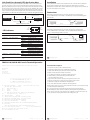
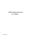
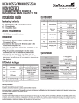
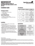
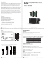
Introduction
CTC Union Technologies Co., Ltd.
The FRM220 Family are slide-in-line cards for placement in the FRM220 Platform Media
w
Converter Chassis and available in a number of different models that also act as a stand-alone
w
w
.
c
t
c
u
.
c
o
m
converter for placement in one-slot chassis. The FRM220-10/100I is a media converter for
User Guide
10Base-T or 100Base-TX, data transmission over optical fiber media depending on your
specific network needs. All media converters are available with either multi-mode or
single-mode optical transceivers and with connectors for SC, ST or FC. In single mode, WDM
(Wave Division Multiplexing with SC connector) is also available in 20, 40, 60, or 80Km reach,
which will provide the ability to transmit and receive data using only a single optical fiber.
In-band Managed Fiber Media Converter
10/100Base-TX / 100Base-FX – FRM220-10/100I
When the FRM220-10/100I card is placed in the FRM220 rack, the In band management, can
monitor, configure and control the activity of each port for both local or remote sides. For the
UTP side, auto-negotiation is default. You may set data rate to 10Mbps or 100Mbps and
duplex mode to full or half duplex. The Fiber Transceiver Converters give you the freedom to
extend your 10/100Mbps cabling distance by allowing connectivity up to 120 kilometers. Six
LED indicators signal the power status of the converter, UTP port speed, duplex status and
Link/Act and FX port Link/Act and FEF (Far End Fault).
Features
■
■
■
■
■
■
■
■
Auto Negotiation or Manual mode in TP port
Link fault pass through (LFP) function
Forward 2046 bytes packets in switch mode
Forward 9K jumbo packets in Pass through mode
Compatible with FRM220 Chassis In Band Management :
Bandwidth control (32K or 512Kbps x N)
Supports local or remote Monitor (Link/Speed/Duplex/Power)
Supports local or remote Configure
(Speed/Duplex/port disable/Operating mode/bandwidth)
■ Supports remote CPE power fail detect ( dying gasp )
■ Provides Auto Laser Shutdown (ALS) function
■ Supports On-Line F/W upgrade (local or remote)
[email protected]
w
w
w
.
c
t
c
u
.
c
o
[email protected]
m
Specifications
Panel
■ Figure #1. Front Panel of FRM220-10/100I(S)
Standards
IEEE802.3 10BASE-T, IEEE802.3u 100BASE-TX, l00BASE-FX (Fast Fiber, 100Mbps)
Supports Full Duplex Ethernet mode (200Mbps)
FRM220-10/100 family supports transmission of Ethernet packet up to 2046Bytes in size.
Fiber
Connections
10/100BASE-TX RJ-45 Connectors
LEDs
Ethernet
Connections
One RJ-45 connector is provided for connection to MDI-X (To PC) or MDI (To HUB) equipment.
Auto MDI-X allows all UTP connections to be made using only a common straight-through
UTP cable.
RJ-45 Pin
1
2
3
6
MDI-X type
MDI type
Rx+
RxTx+
Tx-
Tx+
Tx Rx+
Rx -
100BASE-TX UTP Cable
Cable type: 100Base-Tx; Category 5 or better
Maximum cable distance: 100 meters (328 feet)
■ Figure #2. Rear Panel of Stand-alone FRM220-10/100I(S)-DC12
FRM220-10/100I(S)-AC/DC48/AD/AD-M
Fiber Optic Connectors
FRM220-10/100I : SC connectors are provided for optic cable connection.
FRM220-10/100IS : one SFP slot with LC connectors is provided for optic cable connection
AC Jack
AC Jack
Power
Switch
Power
Switch
Environment
Power
Switch
Power
Switch
Operating -- 0°C – 50°C, Storage -- 0°C – 70°C,
Humidity -- 10 – 90%, (non-condensing)
DC
Terminal
DC
Terminal
DC Jack
10/100I-DC12
[email protected]
10/100I-AC
10/100I-DC48
Power
Adapter: 12V DC 1A, Built-in AC Power 100~240 V, Built-in DC Power 18~72VDC
Dimensions: (W x D x H) mm
10/100I-AD
10/100I-AD-M
w
w
w
10/100I(S)-DC12 : 88 × 160 × 24
10/100I(S)-DC48 : 135 × 201 × 35
10/100I(S)-AD-M : 135 × 201 × 35
.
c
t
c
u
.
c
o
m
[email protected]
10/100I(S)-AC: 135 × 201 × 35
10/100I(S)-AD: 135 × 201 × 35
w
w
w
.
c
t
c
u
.
c
o
m
Link-Fault-Pass through (LFP) Application Note
Installation
When ‘link fault pass through’function is enabled, link status on TX port will inform the FX
port of the same device and vice versa. From the link fault pass through explanation in the
figure below, if link fail occurrson TX port (1), the local FX port sends non-idle pattern to notify
the remote FX port (2). The remote FX port then forces its TX port to link failed after receiving
the non-idle pattern (4). This mechanism will alert the link fault status of local TX port to the
remote converter's TX port, and the link status of the remote TX port will become down. Link
status LED will also be off for both. Link Fault Pass through is enabled by setting DIP switch 4 (ON).
Connect the Ethernet cable to the E1000/E4000 Series. The converter will sense whether to
(1) TP port link failed
Switch or PC
Fiber
and connect the adapter to an AC outlet.
Connections
10/100/1000BASE-TX port of one HUB to a 1000BASE-FX port of another HUB through the
fiber converter.
remote
Converter A
examplesbelow. Install the fiber converter with the DC power adapter provided (+12VDC, 1A)
The following example illustrates the connection scheme when connecting from a
(3) Fiber port gets remote link fault information
(5) Remote TP link is off
local
operate in Full or Half mode and will be indicated on the LED. Follow the connection
UTP
Converter B
Switch or PC
UTP
Use RJ-45 jack
to HUB connection
Full Duplex
Link off
(2) Fiber port sends non-idle pattern
(4) TP link fail
Figure: Explanation of LFP
1000BASE-FX Fiber
Connection
100
PWR
FULL
FEF
Link/Act
LED Indicators
Link/Act
TX
(NIC) in a computer through the fiber converter.
Function
State
Status
PWR
Power indicator
FX link/Act
Fiber link & activity
On
Off
On
Off
Blinking
On
Off
On
Off
Converter has power.
Converter has no power.
The fiber link is ok.
No link or the link is faulty.
Receiving data on the fiber.
Far end is experiencing link fault.
No fault.
Ethernet operates in 100Mbps
Ethernet operates in 10Mbps
Or no devices attached.
Full duplex mode ( 200mbps )
Half duplex mode ( 100mbps )
The UTP link is ok.
No link or the link is faulty.
Receiving data on Ethernet.
Far End Fault
100
Mode display
Full
Mode display
TX link/Act
Ethernet link & activity
On
Off
On
Off
Blinking
[email protected]
w
w
w
.
c
t
c
The following example illustrates the connection scheme when connecting from a
10/100/1000BASE-TX port of one HUB to a 10/100/1000BASE-TX Network Interface Card
FX
LED
FEF
10/100/1000BASE-TX UTP
straight connection
Fiber Cable
u
.
c
o
m
Use RJ-45 jack
to HUB connection
Full Duplex
10/100/1000BASE-TX UTP
straight connection
Fiber Cable
10/100/1000BASE-TX UTP
straight connection
Full Duplex
Use RJ-45 jack to PC connection
[email protected]
w
w
w
.
c
t
c
u
.
c
o
m
FRM220-10/100I-M-AD Console Terminal Operation
Connect serial console with Hyperterminal or PuTTY with settings:
Functional Descriptions:
38400 baud
1. Port Active: Use this to enable or disable this device
8 bits
2. Negotiation: Switch between Auto and Manual (forced) mode
N no parity
3. Speed: Set the Ethernet speed for forced mode at 10M or 100M
1 Stop bit
4. Duplex: Set the duplex Full or Half for forced mode
no flow control
5. Loop Back Test: Perform the non-intrusive OAM loop back test
6. Operation Mode: Sets between Switch (store&forward) and
Converter ( jumbo frame ) modes
****************************************
***
CTC UNION TECHNOLOGIES CO.,LTD
***
FRM220 10-100I Manager Ver:1.68 ***
7. Ingress RL: Set the electrical to optical speed in granules of 32K or 512K
***
8. Egress RL: Set the optical to electrical speed in granules of 32K or 512K
9. LFP: Enable or disable the Link Fault Pass Through function
****************************************
A. Auto Laser Shutdown: Enable or disable the ALS safety function
<1>: Port Active [Enable]
UTP Link:[Up]
[Local]
B. Remote Reset: Send reset code to remote unit (remote must be set to accept remote reset)
[Ver:1.100-1.688-0.000-0.000]
C. Port Reset: Resets the Ethernet chip
Rx Active:[Off]
<2>:
Negotiation:[Auto
]
D. Local card menu: If this card has SFP, then this menu item can view the SFP info
<3>:
Speed:
[ 100
]
M. In Band Mgmt: Use this to enable or disable the OAM in-band management function
<4>:
Duplex:
[ Full ]
FX
<5>:
N. Go to remote card menu: Using OAM, enter the configuration screen for the remote card
Link:[Up] Rx Active:[Off] FEF:[Off] Remot PWR:[non]
Loop Back Test:[Off]
<6>: Operation Mode:
S. Store parameters: Selecting enable will save the settings to the card
Status:[----]
[Switch]
<7>: Ingress Rate Limit<IRL> Mode: [No Limit][100.0M]
<8>: Egress Rate Limit<ERL> Mode:
[No Limit][100.0M]
<9>: Link Fault Pass Througth<LFP>:[Disable]
<A>: Auto Laser ShutDown<ALS>:
[Disable]
<B>: Send Remote Hardware Reset <M>: In Band Management:[Enable]
<C>: Port Reset
Small Form Pluggable:[No] Digital Diagnostic<D/D>:[No]
<D>: Go to Line Card Status menu
<N>: Go to the Remote menu.
<ESC>: Go to Prvious menu. Plese Select an item
<S>: Store Parameter for Local
[email protected]
w
w
w
.
c
t
c
u
.
c
o
m
[email protected]
w
w
w
.
c
t
c
u
.
c
o
m