1
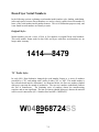
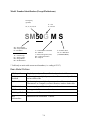
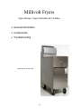
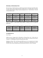
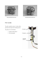
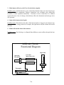
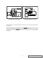
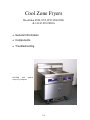
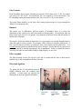
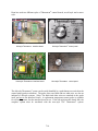
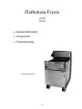
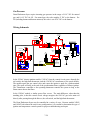
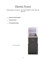
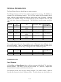
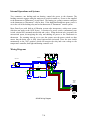
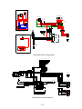
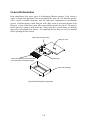
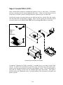
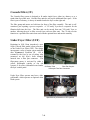
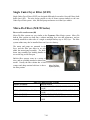
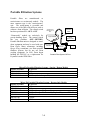
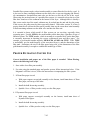
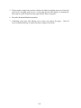
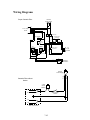
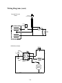
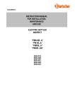
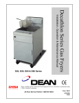
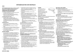
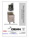
Dean Equipment
•Fryer Serial Numbers
Slide Show
•Model Number Identification
•Model Prefixes
•Millivolt Fryers
Slide Show
•Cool Zone Fryers
Slide Show
•Triathlon Fryers
Slide Show
•Flatbottom Fryers
Slide Show
•Electric Fryers
Slide Show
•Filtration
Slide Show
7-1
Return to Cover
Dean Fryer Serial Numbers
In the following sections explaining serial number/model number style, shading, underlining,
italics and spaces between letters/numbers are used to clearly explain what each number or
letter of the serial number/model number denotes. This is for illustration purposes only, and
is not found in serial numbers on Dean fryer units.
Original Style:
Model numbers precede a series of four or five numbers in original Dean serial numbers.
This serial number format ended in late-1988, and fryers with these serial numbers are no
longer under warranty.
1414— 8479
"W" Prefix Style:
In early-1989, Dean Industries changed the serial number format to a series of numbers
preceded by a "W", and ending with a suffix of either "SS" or "MS". The model number is
not referenced and must be determined. As illustrated below, the first two numbers (shaded
dark-gray) represent the month of production. The next two numbers (underlined) indicate
the year of manufacture. The remaining series of numbers denote the manufacturing
sequence and are not significant. The last two letters (shaded light gray) denotes the material
used in vessel construction (SS = Stainless Steel and MS = Mild Steel).
W048968724SS
7-2
Single-Letter Style:
From early-1994 through mid-1997, Dean Industries used another type of serial number.
Serial numbers in this period include a letter after the eighth or ninth number. As illustrated
below, the first set of five or six numbers (shaded dark-gray) are the sales order number. The
next three numbers (underlined) denote the manufacture order for each individual unit (e.g.
001, 002, etc.). The letter (A— L) preceding the unit number is the month of production,
followed by the year of manufacture (shaded light gray). The model number is required to
determine material used in construction. An "S" (not shown) at the end of the model number
denotes stainless steel construction; no "S" denotes mild steel construction.
No information about filtration systems, computer configurations, basket lifts, etc., is
contained in the previously discussed serial-number formats. Field service-technicians or
store personnel must determine what options are present at the time of service. In some
cases, Frymaster Technical Service card files will indicate fryer configuration, but not
always. Configuration options must be confirmed at the fryer location as files in the
Frymaster Technical Service Department only cover a limited range of serial numbers.
45729001D95
Current Style:
Beginning in mid-1997 (current production), Dean Industries revised their serial number
format to resemble the Frymaster serial-number system. As illustrated below, the first four
digits (shaded dark-gray) indicate the year and month of manufacture (98=1998; 07=July).
The two letters in the fifth and sixth position (shaded light gray) denote the class code by
fryer. The last four numbers (underlined) denote the manufacturing sequence for that month.
9712GA0001
7-3
Model Number Identification (Except Flatbottoms)
Oil capacity
(pounds):
G = Gas
E = Electric
20, 35, 50, 60, 80
SM50G M S
SR = Super Runner
SM = Super Marathon
D = Decathlon
T = Thermatron® Controlled
M = Millivolt
I = Electronic Ignition (24V)
HP = High Performance
DI = Drop In
TC = Counter Top
PC = Pasta Cooker
BG = Bagel Boiler
RG = Rethermalizer
S= Stainless Steel
No "S"= Mild Steel
(* See note below)
* Valid only on units with current serial numbers (i.e. ending in "F95").
Dean Model Prefixes
(SR) Super Runner
Single fryers only, no filter, millivolt only, no basket lifts.
(SM) Super
Marathon
Can be single or multiple fryers, can have filtration, usually millivolt,
can have basket lifts.
(D) Decathlon
Can be single or multiple fryers, can have Electronic Controls
(Thermatron® or Computer) can have filtration, can have basket lifts.
(TC) Triathalon
Counter top fryer. Millivolt or Electronic Control
(PC) Pasta Cooker
Tube type with Thermatron® Controls
(BG) Bagel Boiler
Flatbottom with Thermatron® Controls
(RG)
Rethermalizer
Flatbottom with Thermatron® Controls
7-4
Model Number Identification (Flatbottoms)
2424G TI
Fry-vessel dimensions,
( i.e. 24" x 24").
G = Gas
E = Electric
T = Thermatron® Controlled
I = Electronic Ignition (24V)
7-5
Return to Dean Table of Contents
Millivolt Fryers
Super Runner, Super Marathon & Triathlon
•General Information
•Components
•Troubleshooting
Super Runner 42 Gas Fryer
7-6
GENERAL INFORMATION
The most basic of the Dean fryers are millivolt-operated and thermostat-controlled models.
The Super Runner (SR) and Super Marathon (SM) models are essentially alike in operation,
with the primary difference being oil capacity and physical size. The table below covers the
current production units.
MODEL
SM20G
SM35G
SM50G
SM60G
SM80G
OIL CAPACITY
20-23 lb.
35-43 lb.
35-50 lb.
60-75 lb.
80-100 lb.
BTU.
50,000
90,000
115,000
150,000
165,000
FRYING AREA
6 ½” x 14”
14” x 14”
14” x 14”
18” x 18”
20” x 20”
CONTROLS
Millivolt
Millivolt
Millivolt
Millivolt
Millivolt
Dean also produces a model SR38G (Super Runner), economy gas fryer for light duty
applications.
MODEL
SR38G
SR42G
SR52G
OIL CAPACITY
35-44 lb.
35-43 lb.
35-50 lb.
BTU.
90,000
105,000
120,000
FRYING AREA
12” x 14”
14" x 14"
14" x 14"
CONTROLS
Millivolt
Millivolt
Millivolt
COMPONENTS
Gas Valves
Millivolt units are equipped with a Robertshaw or Honeywell gas valve. Both valves are
powered by a thermopile (or pilot generator) and do not require an external electrical source
to operate. The thermopile is also part of the pilot safety circuit.
Beginning in March 1994, the Honeywell millivolt gas valve was phased into the Super
Marathon Fryer line. Some units (i.e. SM20) may still incorporate a Robertshaw gas valve.
The SR38 fryer has been manufactured with the Honeywell gas valve from its inception.
7-7
Honeywell Millivolt Gas-valve
Robertshaw Millivolt Gas-valve
Pilot Assembly
The pilot assembly consists of a pilot orifice,
pilot hood, thermopile and mounting bracket.
Pilot Hood
The pilot serves two functions:
1. Lights the main burners
Thermopile
2. Heats thermopile.
Mounting
Bracket
7-8
Thermostats
The Robertshaw or Sunne operating-thermostats used in Dean millivolt fryers are accurate to
within approximately 15°F. The manually operated thermostat operates in a range of 200400°F and is used in all Dean millivolt fryers.
The high-limit thermostat acts as a safety switch to protect from extremely high oil
temperatures. If the oil temperature exceeds the manufacturer’s pre-set temperature of 425450°F, the high-limit will open and de-energize the gas valve. The high-limit thermostat is
wired into the pilot-valve coil circuit. When the high-limit switch is open, the gas valve loses
power, and both pilot and main burners are extinguished.
Gas Pressure
With the exception of Triathlon (TC25 and TC35) and the SR38G fryers, Dean millivolt
fryers all operate on the same gas pressure, depending on gas type. For natural gas, the valve
supplies 4" WC to the burners. For LP (including butane and butane mixtures) the valve is
set at 10" WC to the burners. These fryers all require incoming gas pressure in the range of
6-14" WC for natural gas, and 10-14" WC for LP.
The burner flame should be a rich, blue color, turning yellow/orange as it goes through the
diffusers in each burner tube.
Troubleshooting
Millivolt Electrical Circuit Troubleshooting
There are some basic troubleshooting procedures that will help solve many millivolt fryer
problems.
Some of the most frequent problems are:
1. Pilot light will not light.
Probable causes: no gas supplied to fryer, bad gas valve, or clogged pilot orifice.
2. The pilot light lights, but doesn’t stay lit when gas valve button is released.
Probable causes: open high-limit thermostat, low output from thermopile, or bad wire/wiring
connections.
7-9
3. Main burner will not cycle ON as oil cools below setpoint.
Probable causes: bad thermostat or poor connections/terminal crimps on wires between gas
valve and/or other components. Replace crimped-on wire terminals with soldered-on
terminals to ensure optimum connections. Corrosion or loose connections in a millivolt
system will cause a loss of voltage, which directly affects the thermostat and main gas valve
coil operation.
4. Some of the burners don’t ignite.
Probable causes: flame holes in the sides of the burner heads are clogged, or the burners may
be installed in the wrong position (for example, the right burner only has a flame hole on the
left side).
5. Flame rolls out the front of the burners.
Probable causes: flue blockage or collapsed flame-diffusers restrict airflow through the heat
tubes.
Millivolt Circuit:
Functional Diagram
High Limit
Operating
Thermostat
Gas Valve
Main Valve Coil
Pilot Coil
Thermopile
Pilot
7-10
Combination Gas
Valve
White
Thermopile
Combination
Gas Valve
Red
Pilot Knob
Operating
Thermostat
TH TH
TP
Black
Black
Red
Red
Safety Valve
High-Limit
Vent
ROBERTSHAW
Red
Black
Red
TP
Red
Red
Operating
Thermostat
Black
Yellow (Braided)
Orange (Braided)
Red
Thermopile
Red
Hi-Limit
Black
Red
Black
Black
Robertshaw Millivolt Gas Valve Wiring
Honeywell Millivolt Gas Valve Wiring
Although different in wiring and appearance, both types of gas valves operate similarly in
their function.
It is also important to note that Dean fryers using Honeywell millivolt gas valves are wired
differently than Frymaster Honeywell millivolt gas valves. Although the valves are similar
in appearance, the two systems will not work properly unless the correct wiring schematics
are followed.
7-11
Return to Dean Table of Contents
Cool Zone Fryers
Decathlon (D20, D35, D50, D60 D80)
& 1414/1818/2020G
•General Information
•Components
•Troubleshooting
SCFUD60
with
optional
Compu-Fry Computer
7-12
GENERAL INFORMATION
Dean Decathlon gas fryers are manufactured in a variety of different sizes and capacities.
There are also significant differences in ignition and control systems. The Decathlon Cool
Zone fryers are tube-type fryers, and may incorporate many combinations of multiple-fryer
options (possibly different models in the same battery), automatic basket lifts, and built-in oil
filtration systems.
Major Decathlon models are listed in the table below:
MODEL
D20G
D35G
D50G
D50GHP
D50GDD
OIL
CAPACITY
20-23 lbs.
35-43 lbs.
35-50 lbs.
35-50 lbs.
35-50 lbs.
BTU.
50,000
90,000
115,000
120,000
115,000
FRYING
AREA
6 ½" x 14"
14" x 14"
14" x 14"
14" x 14"
14" x 14"
D60G
D60G (HP)
D80G
D80G (HP)
60-75 lbs.
60-75 lbs.
80-100 lbs.
80-100 lbs.
150,000
150,000
122,000
165,000
18" x 18"
18" x 18"
18" x 18"
20" x 20"
COMMENTS
2 burners
3 burners
4 burners
4 burners
4 burners (Vessel is 6"
deeper than D50G)
5 burners
5 burners
5 burners
5 burners
COMPONENTS
Temperature Control Systems
•
•
•
•
•
Basic operating-thermostat
Solid-state Thermatron®
Thermatron® primary with optional thermostat backup
Computer (either Dean/Frymaster or Fast computer)
Computer with either Thermatron® or thermostat backup
Ignition System
• Standing pilot with 120-volt gas valve
• 24-volt electronic ignition (Pilot lights first, then main burners after the pilot flame is
proved.)
Gas Valves
Decathlon fryers are currently equipped with a Honeywell gas valve, but older units may be
equipped with a Robertshaw or White Rogers gas valve.
7-13
Gas Pressure
Dean Decathlon fryers require incoming gas pressure in the range of 6-14" WC for natural
gas, and 10-14" WC for LP. For natural gas, the valve supplies 4" WC to the burners. For
LP (including butane and butane mixtures) the valve is set at 10" WC to the burners.
The burner flame should be a rich, blue color, turning yellow/orange as it goes through the
diffusers in each burner tube.
Burners
The easiest way to differentiate between models of Decathlon fryers is to check the
dimensions of the cooking area and/or the number of burners/tubes. As seen in the table on
the previous page (there are exceptions), most models are different in size and the number of
burner/tubes contained.
The burners, which are similar in appearance in a given model, are actually manufactured as
either left, right or center versions. For example, a D20 will have a left and a right burner. A
D60 with five burners will have a left burner, three center burners and a right burner. It is
essential that the burners be installed in the correct location. If more than one is removed at a
time, they should be marked appropriately for re-installation. Failure to install the burners
correctly will result in some burners failing to light properly, or not at all.
Pilot Assembly
The pilot assembly for the 120-volt gas valve unit is constructed the same as that used in
millivolt fryers and accomplishes the same function.
Electronic Ignition
The igniter for the 24-volt ignition system is
slightly different from the standard pilot
assembly. A flame-sense rod replaces the
thermopile in electronic ignition assemblies.
Cool Zone
Ignitor
7-14
Cool Zone
Flame-Sense
Rod
D20 D.S.I.
Pilot
Assembly
Temperature Controls
The Robertshaw or Sunne operatingthermostat and high-limit thermostat used in
these fryers are the same components used in
the Super Marathon millivolt fryers.
In the Decathlon series however, the highlimit thermostat is normally wired in series
with the gas valve main coil, instead of the
pilot coil. When the high-limit switch opens,
it cuts power to the gas valve, and
extinguishes the main burners.
Operating-Thermostat
High-Limit
Many Decathlon fryers use a solid-state temperature controller, or Thermatron® controller
instead of the basic thermostat. A Thermatron® system incorporates a temperature-control
circuit board, a potentiometer, and a temperature probe. This system is more accurate and
more reliable than a standard thermostat, but is also more expensive to purchase, repair or
replace. The temperature probe is different from the operating-thermostat in that it is much
thinner, and is the same diameter its whole length.
Unlike a standard thermostat, a Thermatron® probe works by comparing resistance through
the probe circuit to the resistance set in the potentiometer (which corresponds to desired
temperature). To check controller and probe accuracy, it is necessary to measure the probe
circuit resistance with an ohmmeter and measure the actual oil temperature.
7-15
Dean has used two different styles of Thermatron® control boards, an old style and a newer
style.
Old-style Thermatron® interface board
Old-style Thermatron® control panel
New-style Thermatron® interface board
New-style Thermatron® control panel
The old-style Thermatron® system can be easily identified by a push-button test switch on the
control panel (probe test button). The probe wires, one black and one white wire, are also an
indicator of old-style systems. (Note: The black and white wires are attached to the probe
itself, and not to the interface board). A replacement temperature-sensor probe is available
for old-style systems, but the interface board is not. If the old-style interface board fails, the
complete system must be retrofitted with the new-style "G0" Thermatron® system.
7-16
The new "G0" Thermatron® system can be identified by the absence of a test button on the
controller. Also, both wires connected to the probe are either dark brown or black. None of
the parts for the two systems are interchangeable.
The temperature/resistance
characteristics are very different for each probe and the corresponding circuit board.
Some Cool Zone fryers, especially for some major restaurant chains like Chili’s, may use a
computer control system. It replaces the Thermatron®, and functions similarly while adding
cook cycle timing and temperature/timing sensitivity. The computer temperature probe looks
similar to the Thermatron® probe, but is much different in resistance. Confirm the system
type installed into the unit when servicing or ordering parts. For the temperature vs.
resistance readings on the probes, refer to the charts in the appropriate section.
Dean electronic ignition fryers incorporate a variety of ignition modules. Decathlon fryers
have been manufactured with Robertshaw ignition modules, which sense flame through a
separate flame-sensing wire. The Honeywell module senses flame through the high-voltage
wire.
Either of these Robertshaw
modules is acceptable for use in
Decathlon fryer systems.
The Honeywell ignition module
senses flame through the highvoltage wire.
The modules above are examples of the "dual-stage" ignition module. An electronic spark
lights the pilot, then the main valve opens after the pilot flame is "proved". The Robertshaw
dual-stage ignition module is currently the only module used. The Honeywell dual-stage
module should not be used at this time due to occasional problems with inconsistent ignition.
7-17
7-18
TEMP
SENSOR
1
2
1
2
1 2 3 4
1 2 3 4
POT
1
2 3 4
1 2 3 4
GAS
VALVE
5
6
5 6
PV
MV
MV/PV
GND
IGN
TR
SEN
TH
OPTIONAL
BOIL OUT
SWITCH
C
1 2 3 4 5 6 7 8 9
RELAY
R1
120 VAC
4
2
31
POWER SWITCH
14
3
7
8
9
10
11
12
TEMP
SENSOR
120 VAC "GO"
SOLID STATE
TEMPERATURE CONTROLLER
13
2
1
1 2 3 4 5 6 7 8 9
1 2 3 4 5 6 7 8 9
IGNITION
MODULE
115 VAC
POWER
SUPPLY
1 2 3 4 5 6 7 8 9
SENSOR
IF INSTALLED,
BOIL-OUT CIRCUIT
WILL BE DUPLICATED
FOR BOTH THERMATRONS
BACK-UP
OPERATING
THERMOSTAT
115V
24V
IGNITOR
HI-LIMIT
THERMOSTAT
LEFT FRYER
1
2
1
2
1 2 3 4
1 2 3 4
POT
ON-OFF-0N
POWER SWITCH
1
14
3
7
8
9
10
11
12
120 VAC "GO"
SOLID STATE
TEMPERATURE CONTROLLER
13
2
1 2 3 4 5 6 7 8 9
1 2 3 4 5 6 7 8 9
RELAY
R2
120 VAC
5 AMP FUSE
BACK-UP
OPERATING
THERMOSTAT
1 2 3 4 5 6 7 8 9
1 2 3 4 5 6 7 8 9
24V
GAS
VALVE
SENSOR
IGNITOR
IGNITION MODULE P/N 1906
24V
120 VAC
GAS
VALVE
PV
MV
MV/PV
GND
IGN
TR
SEN
TH
IGNITION
MODULE
MV
MV/PV
PV
GND
GAS
VALVE
(ALTERNATIVE - USED ON OLDER UNITS NO LONGER USED)
IGNITOR
115V
HI-LIMIT
THERMOSTAT
115V 24V
4
2
31
POWER SWITCH
RIGHT FRYER
Wiring Diagram for 2-vat Decathlon Fryer with Thermatron® Controls
TROUBLESHOOTING
Pilot Malfunctions
1. Pilot fails to light.
a. Gas valve on?
b. Check pilot burner adjustment. Adjust pilot flame to extend about 1/2" above the top
of the pilot burner.
c. Check pilot gas line and pilot burner orifice for blockage.
2. Pilot will not stay lit after gas valve knob is released.
a.
b.
c.
d.
Check that thermopile wires are tightly attached at gas valve.
Pilot flame adjustment too low.
Pilot flame not in good contact with thermopile due to drafts or make-up airflow.
Thermopile defective.
3. Pilot flame goes out when burners come on.
a. Pilot flame is too low even though it looks OK. Adjust higher.
b. Incoming gas volume may be low. Check incoming gas connection and supply.
4. Pilot flame is proper size but unstable. Flame waivers or does not envelop the
thermocouple completely.
Check for drafts caused by air conditioning equipment or make-up air.
Main Burner Malfunctions
1. Main burner will not come on – no gas present at main burner.
a.
b.
c.
d.
e.
f.
Gas valve open?
Check pilot light.
Bad gas valve?
Defective high-limit?
Drain valve closed completely? Check reset switch also.
Check probe if Thermatron®-equipped.
2. Main burner flames are small and lazy – oil heats slowly.
a.
b.
Gas pressure below specifications. (4" W.C. for natural gas, 11" W.C. for LP).
Restriction in flue.
7-19
3. Signs of excessive temperature - oil scorched/discolored.
a.
b.
c.
d.
Check thermostat calibration.
Gas pressure above specifications.
Shortening is of inferior quality or used too long.
Short circuit. Check wiring and harnesses.
4. Fryer fails to reach setpoint or runs erratic.
a. Incorrect location of sensor probe or defective probe.
b. Operating-thermostat or Thermatron® controller defective.
5. Fryer comes on when reset switch on drain valve is pressed, but instantly goes out
when reset switch is released.
Drain-valve microswitch is not positioned properly or is defective.
6. Fryer temperature cannot be controlled - runs to high limit temperature.
Defective Thermatron® controller or operating-thermostat.
7-20
Return to Dean Table of Contents
Triathlon Fryers
TC25
TC35
•General Information
•Components
•Troubleshooting
Triathlon TC-25 Millivolt Fryer
7-21
General Information
The Dean line of countertop fryers consists of two fryers, the TC25 and TC35. The models
are very similar in appearance, but quite different in operation. They have two significant
differences. The TC35 has five burner tubes, and may utilize 120VAC for power. The TC25
has only four burners and is strictly a millivolt fryer – it does not utilize 120VAC.
MODEL
TC25
TC35
OIL
CAPACITY
25 lb.
35 lb.
BTU.
FRYING
AREA
12.5" x 14"
14" x 17"
72,000
90,000
COMMENTS
Millivolt
Millivolt/120V
Thermatron®
COMPONENTS
Gas Valves
Triathlon units are equipped with a Honeywell gas valve (natural gas), or a Robertshaw valve
(LP gas). The millivolt units are powered by a thermopile (or pilot generator) and do not
require an external electrical source to operate. The thermopile is also part of the pilot safety
circuit in the 120VAC units.
Gas Pressure
Dean Triathlon fryers operate at the same gas pressure, depending on gas type. Triathlon
fryers require incoming gas pressure in the range of 6-14" WC for natural gas, and 10-14"
WC for LP. For natural gas, the valve supplies 4" WC to the burners. For LP the valve
supplies 10" WC to the burners.
The burner flame should be a rich blue color, turning to yellow/orange as it goes through the
diffusers in each burner tube.
Burners
The incoming gas flows through orifices and
is ignited at the front end of each tube by the
standing pilot. Internal diffusers slow the
flame as it goes through the burner tubes.
This slower and more turbulent flame gives a
much better heat transfer to the walls of the
tubes, thereby heating the oil more
efficiently.
Location of standing pilot
7-22
Pilot Assembly
The pilot assembly for the Triathlon systems is the same as that used in Dean millivolt fryers
and accomplishes the same function.
Thermostats
The operating-thermostat and high-limit used in the Triathlon fryers are the same as those
used in Dean Super Marathon fryers.
Some of the TC35 fryers are operated by 120VAC, and use the Thermatron® temperature
controller instead of the basic thermostat. Triathlon Thermatron® units are not the same as
standard gas Thermatron® units, but do incorporate the same system components.
Both systems use a standing pilot light, which must be lit manually for operation. The
differences are in the gas valve voltage and the valve control system.
WHT
BLK
2 AMP
FUSE
GRN
115V POWER
SUPPLY
POWER SWITCH
SPST
ORG
HIGH-LIMIT
4
BLK
ORG
ORG
BLK
WHT
WHT
BRN
WHT
2 3 4
5 6 7 8 9
1
2 3 4
5 6 7 8 9
2
2
1 2 3 4
ORG
1
ALTERNATE
THERMOSTAT
RED
1
BLK
2 PIN CONNECTOR
(AMP)
WHT
G5RD7
THERMOSTAT
ORG
TC35 Thermatron System with 120V Gas Valve
7-23
120 V
GAS
VALVE
5 6 7 8 9
RED
TEMP
SENSOR
1
BLK
WHT
GRN
ORG
WHT
BLK
WHT
ORG
BRN
WHT
BRN
1
WHT
3
BLK
2
LIGHT
THERMOCOUPLE
TROUBLESHOOTING
1. Pilot fails to light.
a.
b.
c.
d.
Check gas line connection.
Check safety shut-off valve.
Excess air in gas line. Bleed line.
Depress pilot knob for at least one minute when lighting.
2. Pilot fails to remain lit.
a.
b.
c.
d.
e.
Check thermopile leads to ensure leads are connected to gas valve.
Re-light pilot by depressing the pilot knob for longer period of time.
Adjust pilot flame height.
Debris or excess air in gas line.
Verify incoming gas pressure. Minimum readings are 3.5" WC (8.71 mbar) for
natural gas and 10" WC (25 mbar) for propane.
3. Fryer fails to heat fry vessel.
a. Ensure gas valve is ON.
b. Set operating-thermostat temperature to 350°F (177°C). Verify that main burners
light.
c. If burners fail to light, suspect gas valve.
4. Fryer fails to maintain set temperature.
a. Ensure gas valve is ON.
b. Set operating-thermostat to 350°F (177°C) and observe main burners.
c. If burners light, allow fryer to heat vessel and check calibration of operatingthermostat.
5. Fryer runs quickly to high temperature (higher than 400°F/205°C) and remains
there.
a. Faulty operating-thermostat.
6. Fryer temperature is erratic.
a. Check location of temperature probe. If probe is loose, allow fryer to cool, then
reattach probe to heater tube.
b. If probe was attached properly, faulty probe or operating-thermostat.
7-24
Return to Dean Table of Contents
Flatbottom Fryers
1824G
2424G
•General Information
•Components
•Troubleshooting
Dean 2424 Flat Bottom
7-25
GENERAL INFORMATION
MODEL
1824G (T)
OIL
CAPACITY
45-70 lb.
BTU
120,000
FRYING
AREA
18" x 24"
2424G (T)
65-90 lb.
120,000
24" x 24"
CONTROLS
Thermostat (or
Thermatron®)
Thermostat (or
Thermatron®)
Dean Flatbottom fryers are unique in the Dean line. They are the only units that incorporate
draft-inducers, or blowers to move combustion air through the burners. The blower is
mounted in the exhaust flue area and operates by pulling air through the burners. This air
movement directs the combustion products back and forth across the underside of the
flatbottom vessel through a series of baffles, thus facilitating even heat transfer. Because the
draft-inducer operates only during the combustion cycle, cold air is prevented from entering
the combustion chamber and cooling the oil during the coasting or non-heating cycle.
Temperature Control Options
• Standard operating thermostat.
• Solid-state Thermatron® control.
• Thermatron® primary control with thermostat backup.
Ignition System Options
• Standing pilot with 120VAC gas valve.
• Direct spark ignition with 24VAC gas
valve.
Direct Spark Ignition Igniter
7-26
The Honeywell direct-spark ignition module
is used in Dean flatbottom 1824 and 2424 gas
fryers with direct-spark ignition. This module
operates differently from the dual-stage
modules previously discussed, and cannot be
used to replace faulty dual-stage modules.
Although similar to the Frymaster ignition
module, the Dean Honeywell direct-spark
module lacks an "Alarm" terminal. The Dean
Honeywell module should have stickers on
the top or bottom identifying it as an 11second module. The Frymaster and Dean
Honeywell modules are not interchangeable.
Honeywell Direct-Spark ignition module
COMPONENTS
Pilot Assembly
The pilot assembly is constructed the same as pilot assemblies covered in the Millivolt Fryer
section.
Gas Valves
Flatbottom fryers may use either a Robertshaw or Honeywell gas valve. Normally, the
120VAC version uses a Robertshaw valve, and the 24VAC electric ignition version uses a
Honeywell valve.
In the 24VAC version, the temperature-control circuit powers a 120/24VAC transformer,
which powers the module and gas valve. Although there is no actual pilot assembly, the
igniter and flame sensor assembly is often mistaken for a pilot assembly.
The 120VAC valves use a thermopile as part of a safety circuit much like a millivolt valve.
If the pilot is not lit, the gas valve will not open.
7-27
Burners
The flatbottom fryers each have three burner tubes. Each burner has its own orifice, but all
three burners go into a single burner/heat diffuser area under the fry vessel. The flame is
drawn through the diffuser/baffle area where the heat is transferred to the bottom of the
vessel, thus heating the oil.
Front Oil Drain
Front view of burner area
Flame Baffles
Temperature Control Systems
The Thermatron® control system is the standard temperature-control system and may be used
with either the standard 120VAC-gas valve or 24VAC electronic ignition. See the Millivolt
Fryers section for a detailed description of the Thermatron® control system.
The standard Robertshaw or Sunne operating-thermostat and the high-limit thermostat used
in these fryers are the same components used in the Super Marathon millivolt fryers. The
operating-thermostat control system is not very common, and is usually found in older fryers.
In Dean Flatbottom fryers, the high-limit thermostat is wired in series with the gas valve
main coil in a 120VAC system, or on the primary side of the 120/24VAC transformer in a
24VAC ignition system. When the high-limit switch opens, the gas valve or the 24VAC
transformer loses power and shuts off the main burners.
7-28
Gas Pressure
Dean Flatbottom fryers require incoming gas pressure in the range of 6-14" WC for natural
gas, and 10-14" WC for LP. For natural gas, the valve supplies 4" WC to the burners. For
LP (including butane and butane mixtures) the valve is set at 10" WC to the burners.
Wiring Schematic
115V POWER SUPPLY
HIGH-LIMIT
THERMOSTAT
2 AMP FUSE
POWER SWITCH
MOTOR
AIR
PROVER
DSI IGNITION MODULE
1
1
2
115V POWER SUPPLY
2
3
3
4
4
24V
115V
2 AMP FUSE
HIGH
TENSION
LEAD
9-PIN
CONNECTOR
MOLEX
POWER SWITCH
POT
SPARK
IGNITER
FLAME
SENSOR
GAS
VALVE
OPTIONAL
1
2
3
GAS
VALVE
4
120 VAC
120
VAC
120 VAC
24
VAC
2-PIN
CONNECTOR
AMP
RESET
SWITCH
LIGHT
RED
"G0"
SOLID STATE
TEMPERATURE
CONTROLLER
COIL
RELAY
THERMOCOUPLE
TEMPERATURE
SENSOR
VALVE SWITCH
SAFETY SWITCH IF USED
In the 24VAC electric-ignition models, 120VAC from the control circuit passes through the
sail switch, the high-limit thermostat, and the 120/24VAC transformer to the spark module.
The module opens the gas control valve and causes the igniter to spark for a predetermined
time. The spark will stop at the end of the predetermined time regardless of burner ignition.
The Thermatron® controller or the operating-thermostat controls the system as long as the
flame sensor detects the flame.
In the 120VAC models, a similar power flow occurs. The main difference, other than the
standing pilot, is that the control circuit voltage energizes the 120VAC gas-valve main-coil
directly after passing through the blower, the sail-switch, and the high-limit thermostat.
The Dean Flatbottom fryers may be controlled in a variety of ways. Because models 2424G
and 1824G look almost the same in any configuration, it is essential to determine the type of
ignition and temperature control system for proper troubleshooting and repair.
7-29
TROUBLESHOOTING
Pilot Malfunctions
1. Pilot will not come on at all.
a. Gas valve on?
b. Check pilot gas line and pilot burner orifice for blockage.
2. Pilot will not stay lit after gas valve knob is released.
a.
b.
c.
d.
Check that thermopile wires are tightly attached at gas valve.
Pilot flame adjustment too low.
Pilot flame not in good contact with thermopile due to drafts or make-up airflow.
Thermopile defective.
3. Pilot flame goes out when burners come on.
a. Pilot flame is too low even though it looks OK. Adjust higher.
b. Exhaust blower airflow is blowing out flame. Adjust higher.
c. Incoming gas volume may be low. Check incoming gas connection and supply.
Main Burner Malfunctions
1. Main burner will not come on – blower running.
a.
b.
c.
d.
Gas valve open?
Bad gas valve?
Defective high limit?
Blower sail (air-prover) switch defective or not actuating?
2. Blower not operating, although oil temp is below setpoint.
a.
b.
c.
d.
Defective Thermatron® temperature probe.
Foreign material blocking fan wheel.
Defective safety circuit component (if so equipped) or circuit not properly reset.
Blower motor overheated and tripped thermal overload (auto-resets in approx. 30
minutes).
3. Main burner flames are small and lazy – oil heats slowly.
a. Gas pressure below specifications. (4" W.C. for natural gas, 10" W.C. for LP).
b. Restriction in flue.
7-30
Return to Dean Table of Contents
Electric Fryers
Super Runner 38 Electric, 1414/1818/2020E, 18UE/18E/14E,
EH1721
•General Information
•Components
•Troubleshooting
Super Runner SR38E
7-31
GENERAL INFORMATION
The Dean Electric fryers are divided into two main categories.
The SR (Super Runner) and Cool Zone models comprise the first category. The SR38E is an
economy fryer with thermostat controls. The Cool Zone models are all essentially alike in
design, with the primary differences being size, power usage, and oil capacity. Although
208VAC is the standard voltage, the Cool Zone fryers are also available in 240 VAC, 480
VAC, and other voltages used internationally. The table below lists the current production
units.
MODEL
SR38E
OIL
CAPACITY
20-23 lb.
714E
1414E
1818E
22-28 lb.
40-55 lb.
70-85 lb.
2020E
95-110 lb.
18UE
84-103 lb.
* Indicates high performance
kW
FRYING AREA
12.0 / 14.0 / (21.0
HP*)
9.0
18.0
13.5 / 18.0 / (21.0
HP*)
13.5 / 18.0 / (21.0
HP*)
17 / 20.5
12" x 14"
PRIMARY
CONTROLS
Thermostat
6 3/4" x 14"
14" x 14"
18" x 18"
Thermatron
Thermatron
Thermatron
20" x 20"
Thermatron
18" x 24"
Thermatron
The second category of electric fryers includes a pair of flatbottom fryers, differing only in
size and oil capacity. These are essentially the same operationally as the Cool Zone fryers,
but structurally different because they are designed to cook a different of product.
MODEL
1824E
2424E
OIL
CAPACITY
35-43 lb.
65-95 lb.
kW
FRYING AREA
19.0
19.0
18" x 24"
24" x 24"
PRIMARY
CONTROLS
Thermatron
Thermatron
COMPONENTS
Fixed Elements
All Cool Zone and Super Runner fryers, with the exception of the Model 714, have three
identical elements. The Model 714 has only one element. It is, however, a higher-rated
element than the elements used in Dean electric fryers.
The flatbottom models also have three heating elements. The middle element is different
from the side elements in electric Flatbottom fryers. The side elements are often hard to see
7-32
since they are normally under protective guards on each side of the vessel. The side elements
are identical, and have the same part number for both the left and right side.
The elements in both types are normally wired for three-phase power, but may be wired
single-phase if permitted by local electrical code and the wire size is adequate.
Unlike the Frymaster electric elements, most Dean elements do not tilt, or lift out of the
frypot. They are mounted through the front wall of the vessel. The notable exception are the
Ultimate Electric (UE) models which have Frymaster-type tilting elements.
Ultimate Electric Models
Ultimate Electric fryers use a tilt-element
system similar to Frymaster's electric fryers.
The Dean 18UE fryer is a new style fryer
manufactured by Dean Industries. Originally
built for KFC, it is now being sold to other
restaurants. It is a high-volume fryer with a
built-in filtration system. The frypot design
differs from all other Dean designs.
Production began in October 1998, with
several prototypes in service in various parts
of the world. It incorporates a combination
of Dean and Frymaster technology, including
Frymaster components such as elements and
controllers.
Dean has built other tilt element fryers based
on the 18UE prototype. KFC and Taco Bell
use the 18E and 14E fryers. The 18E is
essentially a 18UE fryer with a KFC-1
Computer and KFC-style drain system.
KSCFH18E Electric Fryer
The 14E has a 14" x 14" cooking area, while the 18E has an 18" x 18" cooking area. A third
18UE variant is the Frymaster EH1721 fryer that shares many common components with the
original 18UE.
7-33
Internal Operations and Systems
Two contactors, one latching and one heating, control the power to the elements. The
latching contactor engages when the main power switch is turned on. Power is also supplied
to the thermostat or Thermatron® circuit board. The heating (or cycling) contactor energizes
as the thermostat or Thermatron® calls for heat. If the high-limit thermostat opens, power is
cut to the coil of the latching relay and to the thermostat or Thermatron® control system.
Most Dean fryers with built-in oil filtration systems also incorporate a safety-reset system
(this does not apply to the 18UE fryers). It consists of a power switch, a momentary reset
switch, a drain-valve mounted microswitch and a relay. When the drain valve is opened, the
microswitch opens, de-energizing the relay and shutting off power to the Thermatron or
thermostat. For morning start-up, or to reset the system, turn the power switch on, then
ensure that the drain valve is fully closed (microswitch activated). Press the reset switch
momentarily to the "ON" position, which will energize the relay and route voltage to the
temperature controller, heat light and heating contactor-coil.
Wiring Diagrams
HIGH-LIMIT
POWER SWITCH
LATCH
CONTACTOR
K2
K1
HEATING
CONTACTOR
FUSE
5 AMP
1
3
5
2
4
6
240V
24V
THERMOSTAT
TERMINAL
BLOCK
P/N 1501-1
6
4
2
5
3
1
GROUND
TERMINAL
SR38E Wiring Diagram
7-34
120VAC
POWER
SUPPLY
4
2
FUSE
3
1
HEATING ELEMENTS
POWER
POWER SWITCH
SWITCH
1
HIGH- LIMIT
THERMOSTAT
2
3
4
120VAC
K2
K1
2
FUSE
5 AMP
3
1
COIL
3
5
2
4
6
4
RESET
4
CONTACTORS
1
24VAC
SWITCH
1
2
6
3
DRAIN VALVE SWITCH
OPTIONAL THERMOSTAT
1
2
3 4
5
6
7
8
9
1
2
3
5
6
7
8
9
FUSE
BLOCKS
POT
OPTIONAL DRAIN VALVE
SAFETY CIRCUIT
1
1
2 3
4
1
2
4
2
3 4
5
6
7
8
9
4
6
4
2
5
3
1
1
3
L3
L2
L1
2
LINE VOLTAGE
3
7
FILTER SWITCH
8
9
10
11
12
CIRCUIT BREAKER
"G0"
SOLID STATE
TEMPERATURE
CONTROLLER
GROUND
TERMINAL
13
14
TEMPERATURE
SENSOR
HEATER - 50 WATT
T5
T4
T8
T3
T2
T1
MOTOR
TO CHANGE DIRECTION OF ROTATION, SWITCH
LEADS T5 & T8 ON MOTOR
FILTER CIRCUIT
Dean Basic Electric Wiring Diagram
208V OR 240V ELEMENTS
L
1
2
3
4
5
6
1
2
3
BRN
4
5
6
7
8
9
R
BRN
BLU
K1
K2
LATCH
CONTACTOR
HEAT
CONTACTOR
BLK#2
BLK#2
WHT#2
WHT#2
WHT
WHT
WHT
BLK#2
BLK#2
BLK#2
T1
FUSE
T2
FUSE
1
BLK#2
240V
240V
(208V)
(208V)
24V
BLK#2
3
5
2
4
6
WHT#2
GROUND
TERMINAL
12V
BLK#2
WHT#2
YEL#2
HI-LIMIT
THERMOSTAT
DRAIN
C6
C
4 WIRE
BLU
NC
MICROSWITCH
BLK
RED
RED
WHT
WHT
RED
BLK
RED
RED
RED
6
3 PHASE
2,4,6
L4
4
2
BLK
RED
5
L3
TERMINAL
3
L2
240V ONLY
1
L1
5
BLOCK
3
1
RED
2
3
4
5
6
7
8
9
10
11 12
1
WHT
TEMP PROBE
J2
1
2
3
4
5
6
7
8
9
10
11
12
3 WIRE
3 PHASE
COMPUTER INTERFACE
GND
6
BOARD
3,6
L3
4,5
L2
1,2
L1
3
4
5
1
2
3
4
5
6
7
8
9
10 11
12 13
14
15
2
1
TO COMPUTER
18UE Electric Fryer With Computer
7-35
TERMINAL
BLOCK
TROUBLESHOOTING
1. The most frequent problem is that the fryer will not heat at all. First, ask these
questions:
a. Is the fryer plugged in (three-phase plug)?
b. Is the three-phase circuit breaker tripped?
c. Is the drain valve microswitch activated (if so equipped)? If so, reset safety switch.
2. If those are OK, next check the temperature control circuit.
a. With unit calling for heat, is there power going into the thermostat/Thermatron
board?
b. If there is no power going into the Thermatron or thermostat, check the safety circuit
for defects in the microswitch and relay.
c. Power in but not out usually indicates a defective thermostat or temperature probe if
the device is set for a temperature higher than the actual oil temp. Check for
continuity/resistance through thermostat or temperature probe. (See applicable
resistance chart for Thermatron.)
d. If the Thermatron probe checks OK, the difficulty is probably in the solid-state “G0”
board.
3. If the fryer heats, but somewhat more slowly than it should, the most probable
causes are:
a. Improper incoming voltage.
b. You may not have all three phases of power to fryer (if three-phase unit).
c. One or more elements may be defective.
d. Heat contactor may not be closing properly on all three contacts.
4. The fryer heats OK sometimes, but occasionally won’t come back on, and the oil
cools below setpoint.
a. If unit is thermostatically controlled, probable cause is a defective thermostat.
b. On Thermatron-controlled fryers, probable cause is the solid-state circuit board.
7-36
Return to Dean Table of Contents
Filtration
Super Cascade; Under Fryer Filter; Cascade; Single Under
Fryer Filter; Micro-Flo/Built-In and Micro-Flo Portable
Filters
•General Information
•Systems/Components
•Troubleshooting
Dean Under Fryer Filter (UFF)
Filtration System
7-37
General Information
Dean manufactures four major types of oil/shortening filtration systems. Each system is
unique in design and appearance, but all accomplish the same job. The filtration systems,
with a couple of notable exceptions, have the same basic components for the filtration
process. Each incorporates a main filter pan, with a filter screen or grid on the bottom of the
filter pan. On top of the filter screen, filter paper and filter powder are placed. The paper is
held in place by a clamp or hold-down ring. Many units have a crumb basket to catch the
larger pieces of sediment (not shown). It is important that the filter pan cover be installed
before operating the filter system.
Filter Paper Hold-down Ring
Filter Pan Cover
Filter Paper
Filter Screen (always ensure that screen
is present before inserting filter paper)
Filter Pan Assembly
Typical Filtration System Components
7-38
Super Cascade Filter (SCF)
Super Cascade filter systems are installed into batteries of two or more fryers. It fits under
two fryers and does not take up any additional floor space. If there are more than two fryers
in the battery, the filter system is normally under the outermost fryers on either end.
On old-style systems, the pump and motor are built into the fryer, and the filter unit couples
onto the pump with a quick-connect coupling. Super Cascade systems are commonly seen in
restaurant chains such as Chili’s Grill, IHOP, and some Long John Silver’s restaurants.
Magnum
Filter
Leaf
Assembly
Old-style Super Cascade Filter System
An optional “Magnum Leaf Filter Assembly” is available for use on Super Cascade filter
systems. It replaces the normal bottom grid, filter paper, hold-down ring, and regular quickconnect with a permanent double-screen filter and standpipe system. The screen assembly is
removable for cleaning, and does not use standard filter paper and powder. This option’s
benefits include the elimination of the cost and problems often associated with paper and
powder systems.
7-39
Cascade Filter (CF)
The Cascade filter system is designed to fit under single fryers, either in a battery or as a
stand-alone fryer-filter unit. Cascade filter units do not require additional floor space. If the
filter is part of a battery, it always is installed under the fryer on the right end.
The filter pump and motor are built into the front of the filter assembly. The unit is selfcontained, just requiring a power receptacle. A "CF-ready" fryer has a receptacle for the
filtration built into the fryer. The filter unit can be moved from one "CF-ready" fryer to
another, allowing the user to filter several fryers with one filter unit. The CF unit can also
function as a portable filter unit when used with the optional hose and nozzle assembly.
Under Fryer Filter (UFF)
Beginning in 1999, Dean introduced a new
Super Cascade Filter model, often referred to
as the Under Fryer Filter (UFF). The design
incorporates a new oil return system modeled
after Frymaster's FootPrint III.
Oil is
returned to the fryer by an oil pickup tube
(mounted on the fryer's front channel)
inserted into a filter pan connector. The
filter-pump motor is activated by either a
yellow pull-handle (similar to the old
system), or by a flat, red handle located under Oil Pickup Tube
the fryer control panel.
Filter Pan Coupler
New-style Filter Pan Connection
Under Fryer Filter systems may have a blue
pull-handle, which operates an optional drain
flush system.
Optional blue pull-handle on UFF systems.
7-40
Single Under Fryer Filter (SUFF)
Single Under Fryer Filters (SUFF) are designed differently from earlier Cascade Filters (built
before late-1999). The new design couples to the oil return system similarly to the new
Under Fryer Filter system. Also, the filter pump and motor are in the fryer cabinet.
Micro-Flo Filters (MF-90 Series)
BUILT-IN FILTER SYSTEMS (BI)
Micro-Flo filter systems are very similar to the Frymaster Filter Magic system. Micro-Flo
built-in filter systems are built into a cabinet matching fryer size and appearance, and are
normally attached to either side of a single or multiple-battery (up to five) fryer. The filter
system cabinet may also be installed between fryers in a battery.
The motor and pump are mounted in the
fryer, and the filter pan slides in on rails
under the motor/pump assembly. The holddown ring normally has latching handles to
secure the ring to the filter pan.
Built-in filter systems come in a variety of
sizes, and are available attached to almost any
model. Usually the filter cabinet has a food
warmer and dump station built into it above
the filter portion.
Micro-Flo Filter
System (MF-90)
Micro-Flo Built-In Filter Systems
MODEL NUMBERS
APPLICATIONS
MF90-12A/15MC
SM20G, SM35G, SM50G, D20G, D50G, 714E,
1414E
MF90-12B/15MC (Low Profile)
SM20G, SM35G, SM50G, D20G, D50G, 714E,
1414E
MF90-18A/20MC
1824G, 2424G, 1824E, 2424E
MF90-20A/20MC
SM60G, SM80G, D60G, D80G, 1818E, 2020E,
18UE
7-41
Portable Filtration Systems
Portable filters are manufactured as
suction/return or suction-only models. The
more common type is the “suction/return”
unit. The motor/pump is reversible and
allows use of the filter with all fryers with or
without a front oil drain. The control switch
has three positions: IN— OFF— OUT.
“Return-only” models are exclusively for
gravity-draining fryers. The control switch
has two positions: OFF— RETURN.
Portable filtration units are designed as standalone equipment and may be used with nonDean fryers. Many restaurants, including
Burger King restaurants, use Dean portable
filtration systems, but do not use Dean
cooking equipment. In 1999, Dean began
building the PF95-LP as a replacement for
Frymaster's model PF90 filter.
Arrows show
direction of oil
flow
Oil Return
Hose
Fryer Vessel
Drain Valve with
Extension
Quick
Disconnect
Filter Pan
Pump
Portable Filter System Oil Flow
Micro-Flo Portable Filtration Systems— Suction / Return Models
MODEL NUMBER
CAPACITY
MF90AU/65
65 lbs.
MF90AU/80
80 lbs.
MF90AU/110
110 lbs. (Also in low profile)
Micro-Flo Portable Filtration Systems— Return-Only Models
MODEL NUMBER
CAPACITY
MF90U/65
65 lbs.
MF90U/80
80 lbs.
MF90U/80 LP
110 lbs. (Low profile filter tank)
PF95-LP
110 lbs. (Low profile filter tank) (Replaced Frymaster PF90 filter)
MF90U/110
110 lbs.
MF90U/160
160 lbs.
MF90U/172
172 lbs.
7-42
Portable filter systems employ a hose/wand assembly to return filtered oil to the fry vessel. It
is also used to rinse remaining sediment out the drain valve to prevent clogging and filteredoil contamination. Suction/Return units also use the hose to suck the oil out of the vessel.
When using the suction feature of a portable filter system, it is essential to keep the tip of the
filter hose wand out of the sediment in the bottom of the fryer. Although there is usually a
filter screen on the tip of the wand, sediment may be sucked into the unit and clog the pump.
If this occurs, the pump must be taken apart and cleaned. With either version, it is best to
gravity drain the oil out into the filter pan if possible, then use the return hose/wand assembly
to flush remaining sediment out the drain valve and into the filter unit.
It is essential to know which model of filter system you are servicing, especially when
requesting parts. Usually, MF90 is the model number on the data plate, regardless of type of
filtration system. The TYPE number, which is normally in a separate block on the data plate,
is extremely important in obtaining the correct replacement parts and filter paper. For
example, a given model number might be MF90AU/80. AU/80 is the TYPE. If the TYPE
is unavailable, get the model/capacity of the associated fryer(s), and the dimensions of the
filter tank. Sometimes, the size of the filter paper being used, or the dimensions of the filter
grid/channel assembly is enough to establish the model/type of filter.
PROPER FILTRATION SYSTEM USE
Correct installation and proper use of the filter paper is essential. When filtering,
observe the following basic steps:
1. Start with a clean filter pan assembly.
2. For units using the standard paper and powder system, follow instructions below. If the
Magnum Leaf Filter is in use, follow the instructions accompanying the filter system.
3. If Dean filter paper is used:
a. With paper support screen/grid assembly on the bottom, install two sheets of Dean
filter paper, one on top of the other.
b. Install the hold-down ring assembly.
c. Sprinkle 16 oz. of filter powder evenly over the filter paper.
4. If Frymaster filter paper is used:
a. With paper support screen/grid assembly on the bottom, install one sheet of
Frymaster filter paper.
b. Install the hold-down ring assembly.
c. Sprinkle 8 oz. of filter powder evenly over the filter paper.
7-43
5. If time permits, dampen the powder with hot oil (either by draining some out of the first
vessel or by scooping some out of a vessel) and turn the filter pump on momentarily.
This ensures a good seal between the paper and the filter screen/grid.
6. Proceed with normal filtration operation.
7. If filtration seems slow after filtering two or three vats, inspect the paper. Clean off
excess sediment build-up, or replace top sheet of paper if necessary.
7-44
Wiring Diagrams
Super Cascade Filter
120VAC
Power Supply
WHT
BLK
GND
WHT
WHT
BLK
PUR
BLK
To LH Fryer
Circuit
BRN
RED
YEL
Fuse
Fuse
RED
BRN
BRN
CB ORG
120VAC/12VAC
Transformer
WHT
BLU
Circuit Breaker
Fuse 20 Amp
BLK
YEL
PUR
YEL
120V
Manual Bypass
Switch
BLU
WHT
ORG
RED
12V
To
Fryer
Controls
120VAC/12VAC
Transformer
RED
24V
120V
RED
NC
NO
COM
BLU
NC
NO
COM
YEL
YEL
YEL
DPDT
24VAC Relay
PUR
RED
YEL#1
YEL
YEL
RED
DPDT
24VAC Relay
24V
BLU
24V
YEL
YEL#1
PUR
YEL
RED
2
1
2
1
NC
COM
NO
Oil Return
Microswitch
7 Amp
Circuit
Breaker
CB
T1
T5
SPST Toggle
Switch
T4
T8
Motor Terminal Box
7-45
GRN
Cascade Filter without
Heater
WHT
BLK
120VAC
Power Supply
Wiring Diagrams (cont.)
Cascade Filter with
Heater
BLK
7 Amp
Circuit
Breaker
GRN
WHT
120VAC
Power Supply
CB
Heater ON
Pump ON
T5
T4
SPDT Toggle
Switch
Probe
Heater
T1
T8
Motor Terminal Box
MF90-BI with Heater
HG
N
BLK
3
5
2
WHT
Ind.
Light
WHT
BLK
6
BLK
Ind.
Light
WHT
BLK
BLK
4
1
Power
Switch
Heater
BLK
Circuit Breaker
WHT
WHT
Pump
Motor
WHT
WHT
WHT
7-46
Wiring Diagrams (cont.)
MF90-BI without Heater
HG
N
WHT
GRN
BLK
Power
Switch
6
3
5
2
4
1
WHT
BLK
WHT
BLK#1
Ind.
Light
BLK#2
BLK
BLK
WHT
Circuit Breaker
WHT
Pump
Motor
WHT
WHT
WHT
MF90 Portable Filter with
Heater and Timer
BLK
GRN
WHT
Timer
Switch
On-Off-Heater
Switch
Pump
Motor
Suction Sump
Heater
7-47
Indicator
Light
Wiring Diagrams (cont.)
MF90A Portable Filter with Reversing
Pump, Heater and Timer
Indicator
Light
Switch Housing
120VAC
Power Supply
BLK
GRN
WHT
ON-OFF-Heater
Switch
Pump Reversing
Switch
Timer
Switch
BLK
Pump ON
Heater ON
WHT
BLK#1
BLK#4
BLK#8
BLK#5
T5
BLK#5
T8
BLK#8
BLK
Suction Sump
Heater
BLK#4
BLK#1
T1
WHT
T4
WHT
Motor Terminal Box
Junction Box
MF90A Portable Filter with Reversing
Pump
120VAC
Power Supply
BLK
Switch Housing
GRN
WHT
Pump Reversing
Switch
Timer
Switch
BLK
BLK#1
BLK#4
BLK#8
BLK#5
BLK#5
T5
BLK#8
T8
T1
T4
BLK#4
BLK#1
WHT
Motor Terminal Box
Junction Box
7-48
Troubleshooting
1. Filter-pump motor stopped suddenly or doesn’t run at all.
a.
b.
c.
d.
Turn unit OFF.
Reset wall circuit breaker.
Press filter reset button.
If motor repeatedly stops, check for blockages in filter pump.
2. Motor fails to run after blockages have been cleared.
a. Reset internal filter pump circuit breaker.
b. Faulty pump motor.
3. Rate of oil return to the fryer is slowing.
a. Filter paper not secured properly by hold-down ring; air is seeping around faulty seal
made by the filter paper and hold-down ring.
b. Improper use of filter paper and filter powder.
c. Sediment is blocking oil-pickup tube in the filter pan bottom.
d. Blockage between the filter pan bottom and oil-return valve.
4. Filter pump motor has suction. No oil is returning to the fryer.
a. Check flexible oil-return hose for blockage. Remove blockage by immersing hose in
hot water to melt shortening. Ensure that the ends of the hose are kept out of water.
b. Blockage is between filter pan and pump. Remove line and clear blockage by
running a cable through the line.
7-49
Dean Table of Contents
Return to Cover