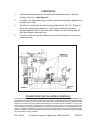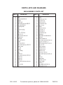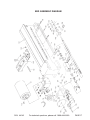
1
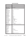
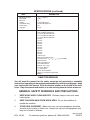
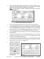
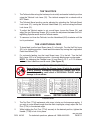
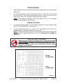
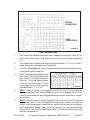
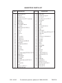
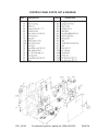
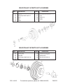
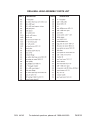
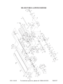
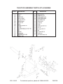
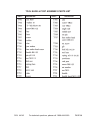
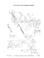
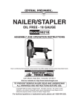
3-IN-1 MULTI-PURPOSE
MACHINE
44142
ASSEMBLY AND OPERATING INFORMATION
Due to continuing improvements, actual product may differ slightly from the product described herein.
®
3491 Mission Oaks Blvd., Camarillo, CA 93011
Visit our Web site at http://www.harborfreight.com
TO PREVENT SERIOUS INJURY,
READ AND UNDERSTAND ALL WARNINGS
AND INSTRUCTIONS BEFORE USE.
Copyright© 2000, 2005 by Harbor Freight Tools®. All rights reserved. No portion of this
manual or any artwork contained herein may be reproduced in any shape or form without
the express written consent of Harbor Freight Tools.
For technical questions and replacement parts, please call 1-800-444-3353.
Contents
SPECIFICATIONS ..................................................................................... 3
GENERAL SAFETY WARNINGS AND PRECAUTIONS ......................... 4
SPECIFIC PRODUCT WARNINGS AND PRECAUTIONS ....................... 6
UNPACKING ............................................................................................. 6
INSTALLATION INSTRUCTIONS ............................................................. 7
PREPARING THE FLOOR MOUNTING SURFACE ............................................... 7
LEVELING AND ANCHORING THE MACHINE TO THE FLOOR SURFACE ........ 8
CONTROLS .............................................................................................. 8
OPERATING INSTRUCTIONS ................................................................. 9
THE CONTROL PANEL SWITCHES ..................................................................... 9
THE MAIN SPINDLE .............................................................................................. 9
THE DRILLING/MILLING SPINDLE..................................................................... 10
THE TAILSTOCK .................................................................................................. 11
THE LONGITUDINAL FEED ................................................................................ 11
TOOL POST ......................................................................................................... 11
CROSS FEEDING ................................................................................................ 12
THREAD CUTTING .............................................................................................. 12
THE THREAD DIAL .............................................................................................. 13
CLEANING AND MAINTENANCE ......................................................... 14
LUBRICATION...................................................................................................... 15
PARTS LISTS AND DIAGRAMS ............................................................ 16
BED ASSEMBLY PARTS LIST ............................................................................ 16
BED ASSEMBLY DIAGRAM ................................................................................ 17
HEADSTOCK PARTS LIST .................................................................................. 18
HEADSTOCK DIAGRAM ..................................................................................... 19
CONTROL PANEL PARTS LIST & DIAGRAM .................................................... 20
IDLER PULLEY A PARTS LIST & DIAGRAM ..................................................... 21
IDLER PULLEY B PARTS LIST & DIAGRAM ..................................................... 21
DRILL/MILL HEAD ASSEMBLY PARTS LIST ..................................................... 22
DRILL/MILL HEAD ASSEMBLY DIAGRAM ........................................................ 23
SPINDLE ASSEMBLY PARTS LIST & DIAGRAM ............................................... 24
SPINDLE FEED ASSEMBLY PARTS LIST & DIAGRAM .................................... 25
MILLING TABLE & APRON PARTS LIST ........................................................... 26
MILLING TABLE & APRON DIAGRAM ............................................................... 27
TAILSTOCK ASSEMBLY PARTS LIST & DIAGRAM .......................................... 28
THREADING DIAL ASSEMBLY PARTS LIST & DIAGRAM ............................... 29
LEADSCREW COVER ASSEMBLY PARTS LIST & DIAGRAM ......................... 29
TOOL SLIDE & POST ASSEMBLY PARTS LIST ................................................ 30
TOOL SLIDE & POST ASSEMBLY DIAGRAM .................................................... 31
PARTS LISTS & DIAGRAMS FOR OPTIONAL PARTS ...................................... 32
WIRING DIAGRAM ............................................................................................... 34
REV 12/05
SKU 44142
For technical questions, please call 1-800-444-3353.
PAGE 2
SPECIFICATIONS
ITEM
DESCRIPTION
Construction
Cast Iron/Machined Steel
Weight
507 Lbs.
Overall Dimensions
62” x 24” x 39”
Lathe Specifications:
Spindle Bore
Spindle Length
Spindle Taper
Lathe Chuck Diameter
Lathe Chuck Runout
Swing Over Bed
Swing Over Cross Slide
Center to Center
Carriage Travel
Cross Slide Travel
Cross Slide Scale
Tool Slide Travel
Tool Slide Scale
Tailstock Quill Travel
Tailstock Quill Taper
Tailstock Quill Lock
Tailstock Scale
Tailstock Center
Thread Indicator
Tool Post/Holder Capacity
Tool Post Style
Tool Post Mounting Hole
Tool Post Mounting Stud
Tool Post Angle
Tool Post Rotation
Bed Ways Length
Bed Ways Width
Height of Bed
Chuck Center Height
Available Threads
1”
13-1/2” From Chuck to Spindle End
MT-4
5”
0.005”
16.5”
6”
31-1/2”
18.1”
7.8”
0.002”
4”
0.002”
3”
MT2
Equipped
0.001”
Dead
Equipped
1/4”min./1/2”max.
Rotating Square - 4 Way
9/16” (12MM)
5/8” (14MM)
900
3600 Counterclockwise
27-3/4”
5-3/8”
8-1/2” From Base
13” From Base
Inches-TPI: 8,9,10,11,12,14,16,18,20,24,32,40
Drill/Mill Specifications:
Mill Spindle Taper
Spindle Travel
Spindle to Column
Nose to Table
End Mill Capacity
Chuck Taper
Drill Chuck Key
Table Size
Drill Capacity
Draw Bolt Thread
Overall Height
Overall Length
Overall Width
Gearbox
Forward/Reverse
R8
4.3”
11.2”
12”
1”
JT33
Standard Key
18-5/8” x 6-1/4”
.8”
13/16” x 1.60 (19MM x 1.60)
37.5”
50”
8.8”
All Speeds Changed by Belt/Gear
Drill/Mill
REV 01/01
SKU 44142
For technical questions, please call 1-800-444-3353.
PAGE 3
SPECIFICATIONS (continued)
ITEM
DESCRIPTION
Maximum Tool Size
Motor RPM
Motor HP
Voltage
Cord/Switch/Plug
Cord Length
Plug Type
1/ ” x 1/ ” Square
2
2
1700
3/
4
110 V Single Phase
UL/CE/CSA Approved
6 Ft.
3-Pole
Accessories:
5.5-7 mm Open End Wrench
8-10 mm Open End Wrench
13-16 mm Open End Wrench
14-17 mm Open End Wrench
17-19 mm Open End Wrench
24 Gear
27 Gear
30 Gear
33 Gear
36 Gear
39 Gear
42 Gear
48 Gear
60 Gear
72 Gear
120/127 Gear
Dead Centers: MT2 & MT4
L-Hex Wrenches: 3/16”,5/16”,7/32”,1/4” (3,4,5,6 MM)
Drill Chuck Key
Lathe Chuck Wrench
Tool Holder Wrench
Outside Jaws (1 Set)
Instruction Manual
1/ ” JT33 Chuck
2
Center Sleeve R8-MT2
Slotted (-) Screwdrivers 100 x 6mm
Wedge
SAVE THIS MANUAL
You will need the manual for the safety warnings and precautions, assembly
instructions, operating and maintenance procedures, parts list and diagram. Keep
your invoice with this manual. Write the invoice number on the inside of the front
cover. Keep the manual and invoice in a safe and dry place for future reference.
GENERAL SAFETY WARNINGS AND PRECAUTIONS
1.
KEEP WORK AREA CLEAN AND DRY. Cluttered, damp or wet work areas
invite injuries.
2.
KEEP CHILDREN AWAY FROM WORK AREA. Do not allow children to
handle this machine.
3.
STORE IDLE EQUIPMENT. When not in use, tools and equipment should be
stored in a dry location to inhibit rust. Always lock up tools and equipment and
keep out of reach of children.
REV 01/01; 02/06
SKU 44142
For technical questions, please call 1-800-444-3353.
PAGE 4
4.
DO NOT USE THIS PRODUCT IF UNDER THE INFLUENCE OF ALCOHOL
OR DRUGS. Read warning labels on prescriptions to determine if your
judgment or reflexes are impaired while taking drugs. If there is any doubt, do
not attempt to use this machine.
5.
USE EYE, HEARING, AND BREATHING PROTECTION. Wear ANSI-approved
safety impact eye glasses, ANSI-approved hearing protection, and ANSIapproved dust protection when working with this machine. ANSI-approved
safety impact eye glasses, hearing protectors, and dust masks are available
from Harbor Freight Tools.
6.
DRESS SAFELY. Nonskid footwear or safety shoes should be used when
working with this machine. Do not wear loose clothing or jewelry as they can
become caught in moving parts. Wear a protective hair covering to prevent long
hair from becoming caught in moving parts. If wearing a long-sleeve shirt, roll
sleeves up above elbows.
7.
INDUSTRIAL APPLICATIONS MUST FOLLOW OSHA REQUIREMENTS.
8.
DO NOT OVERREACH. Keep proper footing and balance at all times to
prevent tripping, falling, back injury, etcetera.
9.
STAY ALERT. Watch what you are doing at all times. Use common sense. Do
not use this machine when you are tired or distracted from the job at hand.
10.
CHECK FOR DAMAGED PARTS. Before using this machine, carefully check
that it will operate properly and perform its intended function. Check for
damaged parts and any other conditions that may affect the operation of this
machine. Replace or repair damaged or worn parts immediately.
11.
REPLACEMENT PARTS AND ACCESSORIES. When servicing, use only
identical replacement parts. Only use accessories intended for use with this
machine. Approved accessories are available from Harbor Freight Tools.
12.
MAINTAIN THIS PRODUCT WITH CARE. Keep this machine clean and dry,
and its moving parts well lubricated. Keep drill bits and other cutting
accessories clean and sharp for better and safer performance.
13.
MAINTENANCE: For your safety, service and maintenance should be
performed regularly by a qualified technician.
14.
USE THE RIGHT PRODUCT FOR THE RIGHT JOB. There are certain
applications for which this machine was designed. Do not use a small tool,
attachment, or machine to do the work of a larger industrial tool, attachment, or
machine. Do not use this machine for a purpose for which it was not intended.
SKU 44142
For technical questions, please call 1-800-444-3353.
PAGE 5
SPECIFIC PRODUCT WARNINGS AND PRECAUTIONS
1.
GROUND THIS MACHINE. The electrical power cord for this machine is
equipped with a grounded 3-prong plug. Never remove the grounding prong or
modify the plug in any way. Do not use adapter plugs with this machine. When
in use, make sure this machine is always plugged into a grounded 3-hole electrical receptacle.
2.
MAKE SURE THE POWER SWITCH IS IN THE “OFF” POSITION BEFORE
PLUGGING IN THE POWER CORD.
3.
DO NOT ABUSE THE POWER CORD. Do not use the cord to pull the 3-prong
plug from a power outlet. Keep cord away from heat, oil, sharp edges, and
moving parts. Replace damaged cord immediately.
4.
KEEP ALL GUARDS IN PLACE, IN WORKING ORDER, AND IN PROPER
ADJUSTMENT AND ALIGNMENT.
5.
REMOVE ADJUSTING KEYS AND WRENCHES. Make sure all adjusting keys
and wrenches are removed from this machine before turning it on.
6.
MAINTAIN A SAFE WORK ENVIRONMENT. Do not use this machine in or
near damp or wet areas. Do not expose this machine to rain. Keep work area
well lit. Make sure there is adequate surrounding work space. Do not operate
this machine in the presence of flammable liquids, gases, or dust. To avoid
accidental electric shock, do not let your body come in contact with grounded
surfaces such as pipes, radiators, ranges and refrigerators.
7.
DO NOT FORCE THIS MACHINE. This machine will do the work better and
safer at the speed and capacity for which it was designed.
8.
SECURE THE MATERIAL. Whenever possible, use clamps or a vise to hold
the material when drilling or cutting.
9.
ALWAYS TURN OFF THE MACHINE’S POWER SWITCH AND DISCONNECT
THE MACHINE FROM ITS ELECTRICAL SUPPLY SOURCE BEFORE PERFORMING ANY SERVICES OR MAINTENANCE such as changing drill bits
and other cutting accessories, leaving the work area, moving the machine from
one location to another, etcetera.
10.
USE CAUTION AS SOME WOODS CONTAIN PRESERVATIVES SUCH AS
COPPER CHROMIUM ARSENATE (CCA) WHICH CAN BE TOXIC. When
drilling or cutting such materials, extra care should be taken to avoid inhalation
and minimize skin contact.
UNPACKING
When unpacking, check to make sure all parts shown on the Parts Lists are
included. If any parts are missing or broken, please call Harbor Freight Tools at the
number shown on the cover of this manual as soon as possible.
Prior to shipment by the manufacturer, the Machine is coated with an
antirust oil. You may wish to clean this off before use.
SKU 44142
For technical questions, please call 1-800-444-3353.
PAGE 6
INSTALLATION INSTRUCTIONS
NOTE: All parts below refer to the parts shown on pages 20, 21, 22, 23, 24,
25, 26, 27, 28, 29, 30, 31, 32, 33, 34, 35, 36, 37, 38, 39 of this manual.
PREPARING THE FLOOR MOUNTING SURFACE
1.
Make sure the floor surface upon which this Machine is to be located is flat,
level, and sturdy enough to bear the weight of the machine, its accessories, and
the working material.
2.
Remove the outer packing/shipping material from the Machine.
3.
Remove the four shipping anchor bolts and nuts that attach the Bed (101) of the
Machine to the wooden shipping skid/pallet.
4.
Caution: When lifting the Machine, make sure to use an overhead hoist, or
lifting device, and hoist chains having a weight lifting capacity sufficient for the
weight of this Machine.
5.
Attach the hoist chains securely to both sides of the Machine. NOTE: Attach
wooden blocks on both sides of the Machine (between the Machine and the
hoist chains) to avoid damaging the Machine. (See Figure A.)
6.
Slowly and carefully lift the Machine off
the wooden shipping skid/pallet, and
set the Machine aside on a flat, level,
sturdy floor surface.
7.
Move the wooden shipping skid/pallet
to the floor location where the Machine
is to be permanently positioned.
8.
Use the four shipping anchor bolt holes
in the wooden skid/pallet as a template
to mark the holes which will anchor the
Machine permanently to the floor.
9.
Set aside the wooden shipping skid/
pallet after the floor anchor holes have
been marked for drilling.
10.
Drill into the floor surface the four
anchor hole marks (minimum hole size to accept a 1/2” diameter foundation
bolt with threads pointing upward.).
11.
NOTE: The four foundation bolts required to anchor the Machine to the floor
surface are not provided. Check with the manufacturer of the foundation bolts
for information on how to securely fasten the bolts to the floor surface.
FIGURE A
SKU 44142
For technical questions, please call 1-800-444-3353.
PAGE 7
LEVELING AND ANCHORING THE MACHINE TO THE FLOOR SURFACE
1.
Once the four foundation bolts are securely fastened to the floor surface, lift the
Machine (see Figure A for instructions) and align the four holes in its Bed (101)
with the foundation bolts.
2.
Slowly lower the Machine over the foundation bolts and onto the floor surface.
3.
Carefully level the width and length of the Machine. If necessary, use the accessory shims provided to raise the end(s) and/or corner(s) of the Machine until
it is level.
4.
Secure the Machine to the floor surface, by wrench tightening the appropriate
size lock washers and nuts onto the foundation bolts (not provided).
5.
Remove the hoist chains from the Machine, and set aside the hoist.
CONTROLS
1. Caution: Do not operate
this machine until you are
completely familiar with
the control parts and
their functions.
(See Figure B.)
2. Before operating, check
to make sure all moving
parts are adequately lubricated.
(See Figure H, page 15.)
FIGURE B
Part
1
2
3
4
5
6
7
8
9
10
11
12
13
Description
Lead Screw Lever
Shift Switch
Change Lever
Emergency Switch/RED
Drilling/Milling Stock Lock Lever (Wrench)
Drilling/Milling Shift Switch
Drilling/Milling Belt Lock Lever
Drilling/Milling Micro Feed Lever
Drilling/Milling Micro Feed Clutch Lever
Drilling/Milling Spindle Feed Lever
Drilling/Milling Spindle Lock Lever
Tailstock Barrel Lock Lever
Tailstock Hand Wheel
Part
14
15
16
17
18
19
20
21
22
23
24
25
26
Description
Screw
Tailstock Lock Lever
Tool Post Feed Hand Wheel
Slide Stock Lever
Cross Feed Clutch Lever
Longitudinal Feed HandWheel
Cross Feed Hand Wheel
Saddle Lock Lever
Half Nut's Lever
Pilot
Master Switch
Returning Screw
Main Spindle Pulley Lock Lever
REV 03/04
SKU 44142
For technical questions, please call 1-800-444-3353.
PAGE 8
OPERATING INSTRUCTIONS
NOTE: All parts below refer to the parts listed on page 8, Figure B of this
manual.
THE CONTROL PANEL SWITCHES
1.
The Machine is equipped with the following switches located on its two control
panels:
a. Green Switch (24) to turn on the Machine.
b. Red Switch (4) to turn off the Machine.
c. Pilot Switch (23) indicates current is flowing through the Machine’s electrical
system and the Machine is in its operating mode.
d. Shift Switch (2) operates the Machine’s Main Spindle in either a stop, forward,
or reverse direction.
e. Drilling/Milling Shift Switch (6) operates the Machine’s Drilling/Milling Spindle
in either a stop, forward, or reverse direction.
2.
NOTE: When working, if the Machine’s control panel doors are opened, the motors of the Machine will automatically shut off.
3.
NOTE: The machine’s motors will automatically shut off or not start, if Part #521,
mill-drill cover (upper), is removed on the run or not installed when turning on the
machine.
THE MAIN SPINDLE
1.
Before starting the Machine, check the tension of the V-Belt. The V-Belt should
depress about 1/2” under normal finger pressure. Too much tension on the V-Belt
will burn out the Main Spindle Bearings. The tension of the V-Belt can be adjusted
with the Main Spindle Pulley Lock Lever (26).
2.
Start the Machine by depressing the Green Switch (24) located on the control
panel.
3.
Use the Shift Switch (2) to engage the Main Spindle and select either the stop,
forward, or reverse running positions. For the stop selection turn the Shift Switch
(2) to its middle position. For the forward running selection, turn the Shift Switch
(2) to the right. For the reverse running selection, turn the Shift Switch (2) to the
left.
4.
To change the Main Spindle RPM, turn the Shift Switch (2) to its stop position.
Depress the Red Switch (4) to shut off power to the Machine and wait until it
comes to a complete stop.
REV 08/02
SKU 44142
For technical questions, please call 1-800-444-3353.
PAGE 9
5.
Release the Main Spindle Pulley Lock Lever (26). Position the V-Belt on the pulleys to obtain the desired Main Spindle RPM. Then, tighten the Main Spindle
Pulley Lock Lever (26) to tighten the V-Belt and lock it in place.
NOTE: The Main Spindle can obtain 7 different RPM settings by following the
chart. (See Figure C.)
FIGURE C
THE DRILLING/MILLING SPINDLE
1.
Start the Machine by depressing the Green Switch (24) on the control panel.
2.
Use the Drilling/Milling Shift Switch (6) to engage the Drilling/Milling Spindle and
select either the stop, forward, or reverse running positions. For the stop selection
turn the Drilling/Milling Shift Switch (6) to its middle position. For the forward
running selection, turn the Drilling/Milling Shift Switch (6) to the right. For the
reverse running selection, turn the Drilling/Milling Shift Switch (6) to the left.
3.
The Drilling/Milling Spindle feed depth can be set with the Drilling/Milling Spindle
Feed Lever (10)
4.
To use the micro feeding feature of the Drilling/Milling Spindle, pull out the Drilling/
Milling Micro Feed Clutch Lever (9). Then use the Drilling/Milling Micro Feed
Lever (8) to obtain the desired feed depth.
5.
To change the Drilling/Milling Spindle RPM, turn the Drilling/Milling Shift Switch
(6) to its stop position. Depress the Red Switch (4) to shut off power to the Machine and wait until it comes to a complete stop.
6.
Pull back on the Belt Lock
Lever (7) to loosen the VBelt. Position the V-Belt on
the pulleys to obtain the
desired Drilling/Milling
Spindle RPM. Then, push
in the Belt Lock Lever (7) to
tighten the V-Belt and lock
it in place. NOTE: The Drilling/Milling Spindle can
obtain 16 different RPM settings by following the chart.
(See Figure D.)
SKU 44142
125
FIGURE D
For technical questions, please call 1-800-444-3353.
PAGE 10
THE TAILSTOCK
1.
The Tailstock slides along the bed ways horizontally and can be locked in position
using the Tailstock Lock Lever (15). The tailstock accepts bits or chucks with a
MT2 Shank.
2.
The Tailstock Barrel position can be adjusted by unlocking the Tailstock Barrel
Lock Lever (12), turning the Tailstock Hand Wheel (13), and re-locking the Barrel
Lock Lever (12).
3.
To adjust the Tailstock center to cut a small taper, loosen the Screw (14), and
adjust the two Returning Screws (25) to make the adjustment between the Drilling/Milling Spindle center and the Tailstock center.
4.
To remove a tool from the Tailstock, turn the Handwheel (915) clockwise until the
tool is pushed out.
THE LONGITUDINAL FEED
1.
To hand feed, turn the Lead Screw Lever (1) to the right. Turn the Half Nut Lever
(22) to its clutching position. Hand feed the material by turning the Longitudinal
Feed Hand Wheel (19).
2.
For automatic feeding, turn the Lead Screw Lever (1) to the left. Turn the Half
Nut’s Lever (22) to its clutching position. Automatic feeding can now be made.
NOTE: By changing the Change Lever (3) and Gear A, B, C, or D 12 different
automatic feed selections can be made. (See Figure E.)
CAUTION! RISK OF KICKBACK!
Never attempt to adjust the Change Lever (3) while the machine
is on or running. Attempting to adjust the Change Lever while
the unit is running could result in PERSONAL INJURY and/or
damage to the machine.
FIGURE E
TOOL POST
1.
The Tool Post (T734) implements click stops to help you find common angles. If
you wish to use a different angle than the click stop angles, simply adjust the Tool
Post (T734) to the desired angle.
2.
While holding the Tool Post (T734) securely in the desired position, tighten the
Handle (T738) to lock it into place.
REV 12/05; 02/06
SKU 44142
For technical questions, please call 1-800-444-3353.
PAGE 11
CROSS FEEDING
1.
Hand feeding can be accomplished by manually operating the Cross Feed Hand
Wheel (20).
2.
For automatic feeding, turn the Lead Screw Lever (1) to the left. Leave the Half
Nut’s Lever (22) in its original non-clutching position. Next, pull out the Cross
Feed Clutch Lever (18). Automatic feeding can now be made.
NOTE: By changing the Change Lever (3) and Gear A, B, C, or D 12 different
automatic feed selections can be made.
THREAD CUTTING
1.
For a thread cutting operation, adjust the Main Spindle to its lowest speed. (See
section “The Main Spindle” for instructions.)
2.
Turn the Lead Screw Lever (1) to the left. Turn the Half Nut's Lever (22) to its
clutching position. Thread cutting can now be made.
NOTE: Different thread pitch (by inch or metric) can be made by changing the
Change Lever (3, Figure B) and Gear A, B, C, or D. (See Figure F1 and page 13,
figure F2.)
CAUTION! RISK OF KICKBACK!
Never attempt to adjust the Change Lever (3) while the machine
is on or running. Attempting to adjust the Change Lever while
the unit is running could result in PERSONAL INJURY and/or
damage to the machine.
METRIC
LEADSCREW
INCH
LEADSCREW
FIGURE F1
REV 12/05; 02/06
SKU 44142
For technical questions, please call 1-800-444-3353.
PAGE 12
METRIC
LEADSCREW
INCH
LEADSCREW
FIGURE F2
THE THREAD DIAL
1.
The Thread Dial indicates the proper time to engage the Half Nut's Lever (22) so
that the Half Nuts will enter the same groove of the thread on each successive
cut.
2.
The Thread Dial is marked with revolving lines numbered 1. 2. 3. 4. 5. 6. Also, a
single (fixed) line is marked on the Thread Dial.
3.
The chart (See Figure G) shows the selection available when matching the revolving lines with the fixed line.
4.
When thread cutting, engage the Half
Nut's Lever (22) at the proper numbers shown on the Scale columns of
the chart. 1-6 on the Scale columns
mean the Half Nut's Lever (22) can
be engaged on any of the revolving
numbered lines 1. 2. 3. 4. 5. 6.
FIGURE G
5.
NOTE: In the first cutting, if you engage the Half Nut's Lever (22) and match the
revolving numbered lines with the fixed line you must also engage the Half Nut's
Lever (22) and match the revolving numbered lines with the fixed line for successive cuttings.
6.
NOTE: You will not need to use the Thread Dial if the Half Nut's Lever (22) and the
Lead Screw Lever (1) are both engaged throughout the process of cutting the
thread. After finishing each successive cut, back off the cutting tool and reverse
the Drilling/Milling Spindle. Then, move the cutting tool to the previous cutting
start position, return the Drilling/Milling Spindle to its forward rotation, and make
the next successive cut.
SKU 44142
For technical questions, please call 1-800-444-3353.
PAGE 13
CLEANING AND MAINTENANCE
1.
Caution: Always disconnect this tool from its electrical power supply before
performing any cleaning, servicing, or maintenance.
2.
To clean, use only a mild detergent and damp cloth. Do not use a flammable or
combustible solvent. Do not allow a liquid to flow inside the Machine. After
cleaning, lubricate all moving parts of the Machine.
3.
If the Spindle Assembly has any play or slop in its movement, the Spanner
Nut (568) may require tightening. Loosen the Pan Phillips Screw (531) and
remove the Cap (530) to access it. After securely hand-tightening the Spanner
Nut (568), replace the Cap (530), and secure the Pan Phillips Screw (531).
REV 12/05
SKU 44142
For technical questions, please call 1-800-444-3353.
PAGE 14
LUBRICATION
1.
The Machine lubricating points should be lubricated (twice daily or daily) according to the chart. (See Figure H)
2.
In addition, the Spindle Bearings should be lubricated with grease regularly and
cleaned once a year.
3.
The Gears in the Headstock should be lubricated with No. 70 or HL-70 gear oil
follow the oil gauge when adding oil. The oil in the Headstock should be
changed regularly; the first time after about 30 days, the second time after 45
days, and thereon once each year.
4.
The Worm Gear and Half Nuts Bearings should be lubricated once a month to
prevent wearing.
FIGURE H
PLEASE READ THE FOLLOWING CAREFULLY
THE MANUFACTURER AND/OR DISTRIBUTOR HAS PROVIDED THE PARTS DIAGRAM IN THIS MANUAL AS A
REFERENCE TOOL ONLY. NEITHER THE MANUFACTURER NOR DISTRIBUTOR MAKES ANY REPRESENTATION
OR WARRANTY OF ANY KIND TO THE BUYER THAT HE OR SHE IS QUALIFIED TO MAKE ANY REPAIRS TO THE
PRODUCT OR THAT HE OR SHE IS QUALIFIED TO REPLACE ANY PARTS OF THE PRODUCT. IN FACT, THE
MANUFACTURER AND/OR DISTRIBUTOR EXPRESSLY STATES THAT ALL REPAIRS AND PARTS
REPLACEMENTS SHOULD BE UNDERTAKEN BY CERTIFIED AND LICENSED TECHNICIANS AND NOT BY THE
BUYER. THE BUYER ASSUMES ALL RISK AND LIABILITY ARISING OUT OF HIS OR HER REPAIRS TO THE
ORIGINAL PRODUCT OR REPLACEMENT PARTS THERETO, OR ARISING OUT OF HIS OR HER INSTALLATION
OF REPLACEMENT PARTS THERETO.
SKU 44142
For technical questions, please call 1-800-444-3353.
PAGE 15
PARTS LISTS AND DIAGRAMS
BED ASSEMBLY PARTS LIST
PART #
SKU 44142
DESCRIPTION
PART #
DESCRIPTION
For technical questions, please call 1-800-444-3353.
PAGE 16
BED ASSEMBLY DIAGRAM
SKU 44142
For technical questions, please call 1-800-444-3353.
PAGE 17
HEADSTOCK PARTS LIST
PART #
SKU 44142
DESCRIPTION
PART #
DESCRIPTION
For technical questions, please call 1-800-444-3353.
PAGE 18
HEADSTOCK DIAGRAM
SKU 44142
For technical questions, please call 1-800-444-3353.
PAGE 19
CONTROL PANEL PARTS LIST & DIAGRAM
PART #
SKU 44142
DESCRIPTION
PART #
DESCRIPTION
For technical questions, please call 1-800-444-3353.
PAGE 20
IDLER PULLEY A PARTS LIST & DIAGRAM
PART #
DESCRIPTION
PART #
DESCRIPTION
IDLER PULLEY B PARTS LIST & DIAGRAM
PART #
SKU 44142
DESCRIPTION
PART #
DESCRIPTION
For technical questions, please call 1-800-444-3353.
PAGE 21
DRILL/MILL HEAD ASSEMBLY PARTS LIST
PART #
SKU 44142
DESCRIPTION
PART #
DESCRIPTION
For technical questions, please call 1-800-444-3353.
PAGE 22
DRILL/MILL HEAD ASSEMBLY DIAGRAM
SKU 44142
For technical questions, please call 1-800-444-3353.
PAGE 23
SPINDLE ASSEMBLY PARTS LIST & DIAGRAM
PART #
SKU 44142
DESCRIPTION
PART #
DESCRIPTION
For technical questions, please call 1-800-444-3353.
PAGE 24
SPINDLE FEED ASSEMBLY PARTS LIST & DIAGRAM
PART #
SKU 44142
DESCRIPTION
PART #
DESCRIPTION
For technical questions, please call 1-800-444-3353.
PAGE 25
MILLING TABLE & APRON PARTS LIST
PART #
SKU 44142
DESCRIPTION
PART #
DESCRIPTION
For technical questions, please call 1-800-444-3353.
PAGE 26
MILLING TABLE & APRON DIAGRAM
SKU 44142
For technical questions, please call 1-800-444-3353.
PAGE 27
TAILSTOCK ASSEMBLY PARTS LIST & DIAGRAM
PART #
SKU 44142
DESCRIPTION
PART #
DESCRIPTION
For technical questions, please call 1-800-444-3353.
PAGE 28
THREADING DIAL ASSEMBLY PARTS LIST & DIAGRAM
PART #
DESCRIPTION
PART #
DESCRIPTION
LEADSCREW COVER ASSEMBLY PARTS LIST & DIAGRAM
PART #
SKU 44142
DESCRIPTION
PART #
DESCRIPTION
For technical questions, please call 1-800-444-3353.
PAGE 29
TOOL SLIDE & POST ASSEMBLY PARTS LIST
PART #
SKU 44142
DESCRIPTION
PART #
DESCRIPTION
For technical questions, please call 1-800-444-3353.
PAGE 30
TOOL SLIDE & POST ASSEMBLY DIAGRAM
SKU 44142
For technical questions, please call 1-800-444-3353.
PAGE 31
PARTS LISTS & DIAGRAMS FOR OPTIONAL PARTS
STEADY REST ASSEMBLY (NOT INCLUDED)
PART #
SKU 44142
DESCRIPTION
For technical questions, please call 1-800-444-3353.
PAGE 32
FOLLOW REST ASSEMBLY (NOT INCLUDED)
PART #
DESCRIPTION
NOTE: Some parts are listed and shown for illustration purposes only, and are not
available individually as replacement parts.
SKU 44142
For technical questions, please call 1-800-444-3353.
PAGE 33
WIRING DIAGRAM
NOTE: There is a micro switch (534) on the parts list on page 17 and shown on the
illustration on page 26, that is attached to the mill-drill head (503) on page 17.
The Micro switch has an extension connected to it (532). When the mill-drill cover
(521) is closed, the mill-drill post (532) is depressed and the micro switch completes
the circuit allowing the machine to be turned on. On the electrical schematic above it is
indicated as S1.
REV 11/05 REV 09/05
SKU 44142
For technical questions, please call 1-800-444-3353.
PAGE 34