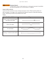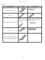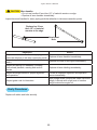
1
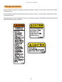
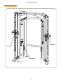
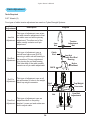
Cybex FT-325
Owners Manual
Strength Systems
Part Number 18000-999-4 B
www.cybexintl.com
Table of Contents
Safety
Safety Guidelines and Practices . . . . . . . . . . . . . . 3
Anchoring Equipment . . . . . . . . . . . . . . . . . . . . . . . 3
Facility Safety Precautions . . . . . . . . . . . . . . . . . . . 3
User Safety Precautions . . . . . . . . . . . . . . . . . . . . . 4
Warnings and Cautions . . . . . . . . . . . . . . . . . . . . . 6
Label Placement . . . . . . . . . . . . . . . . . . . . . . . . . . . 7
Assembly
Machine Specifications . . . . . . . . . . . . . . . . . . . . . . 8
Choosing and Preparing a Site . . . . . . . . . . . . . . . 8
Tools Required . . . . . . . . . . . . . . . . . . . . . . . . . . . . 9
Assembly Procedure . . . . . . . . . . . . . . . . . . . . . . . 9
Exercise
Intended Use . . . . . . . . . . . . . . . . . . . . . . . . . . . . 15
Instructions . . . . . . . . . . . . . . . . . . . . . . . . . . . . . . 15
Maintenance
Warnings . . . . . . . . . . . . . . . . . . . . . . . . . . . . . . . 18
Daily Procedures . . . . . . . . . . . . . . . . . . . . . . . . . 18
Weekly Procedures . . . . . . . . . . . . . . . . . . . . . . . 20
Yearly Procedures . . . . . . . . . . . . . . . . . . . . . . . . 23
Cable Adjustment . . . . . . . . . . . . . . . . . . . . . . . . . 24
Belt Adjustment . . . . . . . . . . . . . . . . . . . . . . . . . . 25
Customer Service
Product Registration . . . . . . . . . . . . . . . . . . . . . . . 26
Contacting Service . . . . . . . . . . . . . . . . . . . . . . . . 26
Ordering Parts . . . . . . . . . . . . . . . . . . . . . . . . . . . 26
Return Material Authorization (RMA) . . . . . . . . . . 27
Damaged Parts . . . . . . . . . . . . . . . . . . . . . . . . . . 27
Cybex® and the Cybex logo are registered trademarks of Cybex International, Inc.
VR3® and its mark are registered trademarks of Cybex International, Inc.
DISCLAIMER: Cybex International, Inc., makes no representations or warranties regarding the contents of this manual. We reserve the right to revise
this document at any time or to make changes to the product described within it without notice or obligation to notify any person of such revisions or
changes.
© Copyright 2013, Cybex International, Inc. All rights reserved. Printed in the United States of America.
10 Trotter Drive Medway, MA 02053 • 508-533-4300 • FAX 508-533-5183 www.cybexintl.com • 18000-999-4 B • July 2013
Cybex Owner’s Manual
Safety
Safety Guidelines and Practices
Read the Owner’s Manual carefully before assembling, servicing, or using the equipment.
Owner must comply with all safety guidelines in this manual. It is also the owner’s responsibility to
instruct users on the safe and proper operation of the equipment and to properly display any and
all warning labels and instructional placards. All users should read these labels and placards before
using equipment.
Death or serious injury could occur if the
following safety precautions and instructions are
not followed.
WARNING
Anchoring Equipment
•
wner should not allow equipment to be used until it is properly anchored
O
as described below.
•
o maximize stability and eliminate rocking, tipping, or falling over,
T
equipment must be anchored to a solid, level surface, utilizing all
anchoring holes provided.
•
asteners must have a minimum of 500 lbs. tensile capacity. Cybex
F
recommends .3/8” grade 2 bolts or better. A minimum pull force of
220 lbs/100 kgs is required for each anchor position.
•
If leg frames do not contact surface, DO NOT pull down with anchors.
Shim any leg or frame not in contact with surface using flat washers.
•
ue to the wide variation of flooring on which machines may be anchored
D
or installed, consult with a qualified and licensed contractor to ensure
proper anchoring and installation.
Facility Safety Precautions
Do not allow anyone, including trainers, to use equipment in a manner other than that shown on the
warning labels and instructional placards located on every machine.
Do not install equipment on an uneven surface. The solid, level surface should not deviate more than
1/8” over a 10’ distance or as defined and required by local building and architectural codes.
3
Cybex Owner’s Manual
It is the responsibility of the facility owner/owner of the equipment to ensure that there is appropriate
clearance around each machine to allow for safe use and passage.
In compliance with the ADA (American Disabilities Act) there must be clear floor space of at least
30 by 48 inches and be served by an accessible route for at least one of each type of exercise
equipment. If the clear space is enclosed on three sides (e.g., by walls or the equipment itself), the
clear space must be 36 by 48 inches.
All other machines must have a clear floor space of 23” for all access point on the machine, unless
shown in the Owner’s Manual.
The dimensions stated in the assembly instructions of this manual include the maximum foot print (in
use) dimensions.
All equipment should be used in a supervised, access-controlled area.
Do not allow equipment to be used by children 12 and under. Supervise disabled and children 13 and
older.
The owner should ensure that regular inspection and maintenance checks as detailed in this manual
are performed. Keep a log of all maintenance and repair activities.
Each day before use, the owner should inspect the equipment. If there are any loose or worn
components such as belts, cables, grips, pulleys, or any missing, damaged labels, or placards, the
owner should fix any deficiencies before they allow the equipment to be used.
Use only Cybex components to maintain and repair the equipment.
Display the Facility Safety Sign so it is visible and prominent.
User Safety Precautions
Owners must instruct users to DO the following:
•
Follow all warning labels and instructional placards when using equipment.
•
Insert weight pin completely before using selectorized equipment.
•
onsult a physician prior to commencing an exercise program. If at any time during exercise you
C
feel faint, dizzy or experience pain, stop and consult your physician.
•
Use a spotter for Free Weight equipment.
Owners must instruct users to NOT DO the following:
•
O NOT pin weights on selectorized equipment in an elevated position or use the machine if
D
found in this position.
•
O NOT increase weight resistance on equipment by any means other than those provided by
D
Cybex.
•
DO NOT wear loose or dangling clothing or jewelry while using equipment. Stay clear of moving
parts.
4
Cybex Owner’s Manual
•
DO NOT lean or pull on machine
•
DO NOT use machine for support during stretching.
•
DO NOT a
ttach resistance straps, ropes or other means to equipment, except those provided by
the manufacturer for intended use on the equipment.
•
DO NOT exceed the maximum specified user weight.
•
DO NOT use if equipment appears damaged or inoperable upon inspection.
•
DO NOT use if guards are missing or damaged.
•
DO NOT remove any labeling from equipment.
5
Cybex Owner’s Manual
Warnings and Cautions
Warning decals indicate a potentially hazardous situation, which, if not avoided, could result in death
or serious injury.
Caution decals indicate a potentially hazardous situation, which, if not avoided, could result in minor
or moderate injury.
The warning and caution decals are shown on the following page. The diagrams following the decals
show where each decal is located.
-X for specifications
WARNING
To minimize risk
of serious injury:
Prior to use:
• Obtain a medical exam
before beginning any
exercise program.
• Obtain instruction before
using.
• Read and understand
warning labels.
• Fully insert adjustment
pins before using.
• Inspect unit, cables, belts,
connections, and guards.
If damaged, worn, frayed,
or missing, notify floor
staff. DO NOT USE.
During use:
• Use only as shown on
instructional placard.
• Do not use for stretching
and do not attach straps
or other devices.
• Do not modify unit.
• Do not allow children 12
or younger to be on or
near unit.
• Notify floor staff if weight
plate is raised. DO NOT
USE.
• Stop exercise if you feel
faint, dizzy, or have pain.
• Use a spotter.
Do not remove this label.
Replace if damaged or
illegible.
MATERIAL:
DIMENSIONS
IN INCHES
DE000001-4
MATERIAL:
FINISH:
ering Drawing DE000005-X
2 DECIMALS ± .03
3 DECIMALS ± .015
ANGLES ± 1°
EXCEPT AS NOTED
GENERAL
TOLERANCES:
2 DECIMALS ± .03
3 DECIMALS ± .015
ANGLES ± 1°
FEATURES SHOWN
PERPENDICULAR OR
PARALLEL SHALL BE
MATERIAL:
SO WITHIN ± 1°
6
REMOVE ALL BURRS
BREAK SHARP EDGES
.005/.010 R
TITLE:
SURFACE FINISH
INDICATED PER
ANSI B46.1-1985
DWG. BY
REMOVE CARBURIZATION
AND SCALE FROM LASER
AND PLASMA CUT EDGES
GENERAL
MACHINING
125
REMO
BREA
.005/.0
GENERAL
TOLERANCES:
ALL MATERIAL MUST COMPLY TO
EUROPEAN UNION DIRECTIVE
2002/95/EC RoHS (RESTRICTION
OF HAZARDOUS SUBSTANCES)
DIMENSIONS
FINISH:
IN INCHES
ALL MATERIAL MUST COMPLY TO
EUROPEAN UNION DIRECTIVE
2002/95/EC RoHS (RESTRICTION
OF HAZARDOUS SUBSTANCES)
EXCEPT AS N
B
REMO
AND S
OWATONNA
AND P
FEATURES SHOWN
PERPENDICULAR OR
GENE
PARALLEL
SHALL BE
DECAL,
WARNING
ENGLISH
SO WITHIN ± 1°
MACH
CHECKED BY
SIZE
SURF
INDIC
ANSI
SCALE
DATE
TECH. PUBS. APPR.
DATE
DATE
MFG. APPR.
DATE
SHEET
DWG. NO.
1:1
1 OF 1
DIMENSIONS
IN INCHES
GENERAL
REV.
DE000001-4
EXCEPT
AS NOTED
REMOVE ALL
BREAK SHAR
.005/.010 R
Cybex Owner’s Manual
Label Placement
8500-025-X
8500-025-X
DE000005-X
DE000001-X
7
Cybex Owner’s Manual
Assembly
Machine Specifications
Total Weight and Size: FT-325
Weight
752 Lbs
Machine Dimensions at Rest
58.88” W x 37.20” L x 83.42” H
342 Kg
149.55 cm W x 94.49 cm L x 211.89 H
Machine Dimensions at Use
Same
Same
Maximum User Weight
Maximum Training Weight
300 lbs/135kg
350 lbs/159kg
Choosing and Preparing a Site
Before assembling the unit, verify the chosen site meets the following criteria:
• Area is well lit and well ventilated.
• Surface is structurally sound and properly
leveled.
• Free
area for access to unit and emergency dismount. Minimum clearance is 23.6 inches
(0.6 meters).
• Adjacent
units may share the free area.
It is the responsibility of the facility owner/owner of the equipment to ensure that there is appropriate
clearance around each machine to allow for safe use and passage.
In compliance with the ADA (American Disabilities Act) there must be clear floor space of at least
30 by 48 inches and be served by an accessible route for at least one of each type of exercise
equipment. If the clear space is enclosed on three sides (e.g., by walls or the equipment itself), the
clear space must be 36 by 48 inches.
All other machines must have a clear floor space of 23” for all access point on the machine, unless
shown in the Owner’s Manual.
The dimensions stated in the assembly instructions of this manual include the maximum foot print (in
use) dimensions.
8
Cybex Owner’s Manual
• Area
is not in the vicinity of high humidity, such as in the vicinity of a steam room, sauna, indoor
pool or outdoors. This unit is designed to function normally in an environment with a relative
humidity range of 30% to 75%.
Exposure to extensive water vapor, chlorine and/or bromine could adversely affect the electronics as
well as other parts of the unit.
• Area
maintains an ambient temperature range of 50° F (10° C) to 104° F (40° C) degrees.
Tools Required
• 9/16” Wrench
• 7/32” Allen wrench
• 1/8”Allen wrench
• 3/4” Socket or wrench
• Hammer
• 3/16” Pin punch
• Loctite® #242
Assembly Procedure
Two people will be required for this procedure.
Read and understand all instructions thoroughly before assembling this unit. Check all items
carefully. If there is damage, see the Customer Service section of this manual for proper procedure to
return, replace, or reorder parts.
Verify parts list shown below.
4800-433
Rope Handle
9
31.8
34.0
70
75
27.2
29.5
25.0
60
100
95
90
EXCEPT AS NOTED
GENERAL
TOLERANCES:
2 DECIMALS ± .03
3 DECIMALS ± .015
ANGLES ± 1°
FEATURES SHOWN
PERPENDICULAR OR
PARALLEL SHALL BE
SO WITHIN ± 1°
MATERIAL:
DIMENSIONS
IN INCHES
ALL MATERIAL MUST COMPLY TO
EUROPEAN UNION DIRECTIVE
2002/95/EC RoHS (RESTRICTION
OF HAZARDOUS SUBSTANCES)
65
22.7
50
55
45.4
18.1
20.4
45
43.1
15.9
DIMENSIONS
IN INCHES
ALL MATERIAL MUST COMPLY TO
EUROPEAN UNION DIRECTIVE
2002/95/EC RoHS (RESTRICTION
OF HAZARDOUS SUBSTANCES)
FINISH:
FINISH:
1
40
MATERIAL:
1. FONT - 40 POINT ARIAL BOLD.
HORIZONTAL SCALE 80%.
TRACKING -50.
NOTES:
1. FONT - 40 POINT ARIAL BOLD.
HORIZONTAL SCALE 80%.
TRACKING -50.
40.8
13.6
30
35
38.6
36.3
NOTES:
80
Decal (80-100)
85
DE000007
9.1
1
11.3
Decal (5-75)
25
DE000006
6.8
1
20
Foot pad
15
16010-311
2.3
4
Diagram
4.5
Description
5
Part Number
10
Qty
OWATONNA
REMOVE ALL BURRS
BREAK SHARP EDGES
.005/.010 R
TITLE:
SURFACE FINISH
INDICATED PER
ANSI B46.1-1985
DWG. BY
REMOVE CARBURIZATION
AND SCALE FROM LASER
AND PLASMA CUT EDGES
GENERAL
MACHINING
125
DECAL, WT PLATE (5 - 75) 2:1
REL
CHECKED BY
SIZE
SCALE
1:1
B
DATE
6-5-13
DATE
SHEET
2 OF 2
DWG. NO.
TECH. PUBS. APPR.
DATE
MFG. APPR.
DATE
DE000006
EXCEPT AS NOTED
GENERAL
TOLERANCES:
2 DECIMALS ± .03
3 DECIMALS ± .015
ANGLES ± 1°
FEATURES SHOWN
PERPENDICULAR OR
PARALLEL SHALL BE
SO WITHIN ± 1°
OWATONNA
REMOVE ALL BURRS
BREAK SHARP EDGES
.005/.010 R
TITLE:
SURFACE FINISH
INDICATED PER
ANSI B46.1-1985
DWG. BY
REMOVE CARBURIZATION
AND SCALE FROM LASER
AND PLASMA CUT EDGES
GENERAL
MACHINING
125
_
REV.
DECAL, WT PLATE (80-100) 2:1
DATE
REL
CHECKED BY
SIZE
B
SCALE
1:1
TECH. PUBS. APPR.
DATE
MFG. APPR.
DATE
6-5-13
DATE
SHEET
2
OF
2
DWG. NO.
DE-000007
REV.
_
Cybex Owner’s Manual
Qty
Part Number
Description
1
12220-005
Handle Assembly
1
51122
Ankle strap
1
GQ000206
Snap link
Diagram
Placement
If
FT-325 can fit through
doorway
Then
Two people will be required for this procedure
1. Move to desired location.
2. Remove the four shipping cones using a 3/4” wrench.
3. Attach foot pads to each foot of frame.
If
Then
Two people will be required for this procedure
1. Remove the four shipping cones using a 3/4” wrench.
2. Attach foot pads to each foot of frame.
3. Remove back panels from machine.
FT-325 cannot fit
through doorway
10
Cybex Owner’s Manual
If
Then
4. Verify weight stack pin is disengaged.
5. Remove spiral pin connecting pulley using a hammer and a 3/16”
pin punch.
Spiral
pin
6. Move pulley and cable connection out of the way.
FT-325 cannot fit
through doorway
7. Remove guide rod caps. Guide rod cap contains a compression
spring that will fly if grasp is not released slowly. Slide spring loaded
guide rod cap down guide rod until cap is clear of frame. Slowly
release grasp of guide rod cap and remove.
8. Remove lifting post.
9. Remove weight plates.
10.Remove plastic insert plug, located at top of machine.
Plastic
Insert
plug
11
Cybex Owner’s Manual
If
Then
11.Loosen the two button head socket cap screws (BHSCS) securing
chin up bar to frame using a 7/32” Allen wrench.
BHSCS
12.Hold thread block in place with fingers and remove the BHSCS.
Thread block
FT-325 cannot fit
through doorway
.
12
Cybex Owner’s Manual
If
Then
13.Remove BHSCS and locknuts, remove one side of connector tubes
using a 7/32” Allen wrench and a 9/16 wrench.
Tube
connector
FT-325 cannot fit
through doorway
14. Move machine to desired position.
15. Reattach frame halves and securely tighten the BHSCS.
16. Place two drops of Loctite 242 to each BHSCS and threaded hole
for Chin up bar. Securely tighten BHSCS.
17. Insert plastic plugs.
Securely anchor machine to the floor
Cybex strongly recommends to maximize stability, equipment must be secured to a solid level
surface.
WARNING: Anchoring equipment:
• Cybex is not responsible for the actual anchoring of equipment. Consult with a
professional contractor.
• Use fasteners having a minimum of 500 lbs. tensile capacity (3/8’’ grade 2 bolts or
better).
• If legs/frame does not contact surface, DO NOT pull down with anchors. Shim
any leg or frame not in contact with surface using flat washers.
13
Cybex Owner’s Manual
Install individual weight plates one at at time
1. Position each weight plate so wide edges of bushings face upward and narrow edges of
bushings face downward.
CT
NG
RE
COR
WRO
Wide bushing
edge faces upward
The narrow bushing edge
must face downward.
2. Install lifting post.
3. Snap guide rods in to position.
Cable routing
1. Place a small amount of loctite® on BHSCS and inside threads of ball stop.
2. Secure cable to ball stop using a 1/8” Allen wrench.
3. Reconnect handle, pulley and cable to platform on both sides.
4. Position pulley mount parallel to the top weight.
5. Pull down on pulley mount until cable is tight.
6. Verify cable is still routed through all pulleys.
7. Attach pulley mount to lifting post with spiral pin using a hammer and 3/16” pin punch.
Spiral
pin
8. Lift top weight up and down simulating normal operation (without selecting any resistance).
9. Verify the cable is moving smoothly.
Install back panels
Verify proper operation
14
Cybex Owner’s Manual
Exercise
Intended Use
The intended use of this machine is to aid or improve general physical fitness and exercise for
commercial use.
Instructions
ead an understand all instructions and warnings prior to using this machine in the Safety
R
section of the Owner’s Manual.
1. Select appropriate resistance.
2. Adjust handles for proper pulley height.
3. Ensure all adjustment knobs are locked into place.
CAUTION: Use only in manner depicted
To avoid serious injury, use equipment only as describe in placards located on each
machine.
CHEST PRESS
OVERHEAD PRESS
Motions Developed
Shoulder Abduction, Elbow Extension
Muscles Used
Anterior Deltoid, Middle Deltoid
Motions DevelopedShoulder Abduction,
Elbow Extension
Shoulder Flexion, Elbow
Extension
Muscles Used
Pectoralis Major
15
Cybex Owner’s Manual
ROW
LAT PULL
Motions Developed
Shoulder Extension, Elbow Flexion
Muscles Used
Lattisimus Dorsi, Teres Major,
Trapezius, Rhomboid, Rear Deltoid
Motions Developed
Shoulder Adduction, Elbow Flexion
Muscles Used
Lattisimus Dorsi, Teres Major,
Trapezius, Rhomboid
TORSO ROTATION
ARM CURL
Motions Developed
Spine Rotation
Muscles Used
External Obliques
Motions Developed
Elbow Flexion
Muscles Used
Biceps Brachii, Brachialis,
Brachioradialis
16
Cybex Owner’s Manual
ARM EXTENSION
SQUAT
Motions Developed
Elbow Extension
Muscles Used
Triceps
Motions Developed
Knee Extension
Muscles Used
Quadriceps, Gluteus Maximus,
Hamstrings, Thoracolumbar Fascia
HIP ABDUCTION
HIP ADDUCTION
Motions Developed
Hip Abduction
Muscles Used
Piriformis, Tensor Fasciae Latae
Motions Developed
Hip Adduction
Muscles Used
Adductor Magnus, Adductor Longus,
Adductor Brevis, Pectineus
17
Cybex Owner’s Manual
Maintenance
All preventive maintenance activities must be performed on a regular basis. Performing routine
preventive maintenance actions can aid in providing safe, trouble-free operation of all Cybex
equipment.
Cybex is not responsible for performing regular inspection and maintenance actions for your
machines. Instruct all personnel in equipment inspection and maintenance actions and also in
accident reporting/recording. Cybex representatives are available to answer any questions that you
may have.
Warnings
Read all warnings in this chapter.
WARNING: For maintenance, service and repair:
• Must be performed by trained service personnel only
• Use only Cybex replacement parts.
Observe the following warnings:
WARNING: Equipment hazard.
To avoid serious injury or death replace worn or damaged components immediately
and keep the equipment out of use until repair is completed.
Daily Procedures
hen using strong cleaning agents such as rubbing alcohol or bleach, it is advisable to first test in an
W
inconspicuous area. Other cleaning agents may contain harsh or unknown solvents and are subject to
formula changes by the product manufacturer without notice. Should you desire to use other cleaning
agents, carefully try them in an inconspicuous area to determine potential damage to the material.
Never use harsh solvents or cleaners which are intended for industrial applications. To clean stained
or soiled areas, a soft white cloth is recommended. Avoid use of paper towels.
Cleaning products may be harmful/irritating to your skin, eyes, etc. Use protective gloves and eye
protection. Do Not inhale or swallow any cleaning product. Protect surrounding area/clothing from
exposure. Use in well ventilated area. Follow all product manufacturer’s warnings. Cybex and its
vendors cannot be held responsible for damage or injuries resulting from the use or misuse of
cleaning products.
18
Cybex Owner’s Manual
Clean Upholstery
If
1.
2.
3.
Light Soiling
4.
Then
Prepare a solution of 10% household
liquid soap and warm water.
Apply with a soft damp cloth.
If necessary, apply a solution of liquid
cleanser with a soft bristle brush.
Dampen a clean soft cloth in water and
wipe residue away.
1. Prepare a solution of 10% household
bleach (sodium hypochlorite) and 90%
water. Dampen a soft white cloth in the
solution.
2. Rub gently on the stained area.
3. Dampen a clean soft cloth in water and
rinse area.
4. If stains are still present, a full strength
household bleach may be used. Allow
bleach to puddle on the affected area
or apply with a bleached-soaked cloth
for approximately 30 minutes. Dampen
a clean soft cloth in water, and rinse
area to remove any remaining bleach
concentration.
1. Dampen a soft white cloth with rubbing
alcohol.
2. Gently rub stained area.
3. Dampen a clean soft cloth in water and
rinse area.
1. Apply a light coat of furniture wax for 30
seconds.
2. Lightly rub area using a clean white cloth.
More Difficult Stains
More Difficult Stains (Alternative Method)
Restoring Luster
Clean Frames
ipe down all frames using a mild solution of warm water and car wash soap. Be sure to dry
W
thoroughly. AVOID acid or chlorine based cleaners and also cleaners containing abrasives as these
could scratch or damage the equipment.
Clean Chrome
Clean chrome tubes, first using chrome polish and then using a car wax seal. Neutral cleaners with a
pH between 5.5 and 8.5 are recommended. Be sure to dry thoroughly. AVOID acid or chlorine based
cleaners and also cleaners containing abrasives as these could scratch or damage the equipment.
19
Cybex Owner’s Manual
Guidelines for cleaning front panel:
se clean soft cloths or sponges for application of cleaners and again for washing and rinsing. Follow
U
up each application with warm water rinse.
•
DO NOT use abrasives or high alkaline cleaners.
•
DO NOT leave cleaners on for long periods, wash immediately.
•
DO NOT apply cleaners in direct sunlight or at elevated temperatures.
•
DO NOT use scrapers, squeegees, or razors.
•
DO NOT clean with gasoline.
Compatible Cleaners and Detergents:
•
Formula 409
•
Top Job
•
Joy
•
Palmolive
•
Windex with Ammonia D
To Minimize Fine or Hairline Scratches:
Mild automotive polish applied and removed with a soft clean cloth will help fill scratches.
Suggested Polishes:
•
Johnson Paste Wax
•
Mirror Glaze #10 Plastic Polish (by Mirror Bright Polish Co.)
•
Novus Plastics Polish #1, #2 (By Novus Inc.)
Weekly Procedures
Inspect All Nuts and Bolts
Tighten all loose nuts and bolts as required.
20
Cybex Owner’s Manual
WARNING: Equipment hazard.
To avoid serious injury or death replace worn or damaged components immediately
and keep the equipment out of use until repair is completed.
Inspect cables and belts
Inspect all cables and belts for wear or damage and proper tension. When inspecting cables and
belts, run fingers on the cable or belt, paying particular attention to bends in cables and attachment
points. The following conditions may indicate a worn cable:
Cables
Condition of Cable
Diagram
A tear or crack in the cable sheath
that exposes the cable
A kink in the cable
A curled sheath
Necking - A stretched cable sheath
21
Cybex Owner’s Manual
Belts
Condition of Belt
3D View
3D or Side View
Peeling of the belt’s skin.
Wave in belt
Belt is necked down (narrow section)
Replace
belt if any Examine edge of belt (both sides).
section is over 1/32” Replace belt if any section is
(.03) narrower than the narrower than the rest.
rest of belt
Cracks or splits
One or more strands of kevlar is
hanging out, or if there is a significant
amount of frayed kevlar.
22
Cybex Owner’s Manual
CAUTION: Worn handles
• Do not use handles if less then 1/8” of material remains on edge.
• Replace all worn handles immediately.
Inspect bars and handles for wear, paying particular attention to tab area connection points.
Replace bar if less
than 1/8” of material
remains to the edge.
Attachment
Hole
Inspection
Inspect bars and handles for wear, paying
particular attention to tab area connection points.
Inspect snap links for proper latching (indicates
wear).
Inspect all labeling for readability, including
instructional placards, warning and caution
decals.
Inspect all weight stacks for proper alignment
and operation.
Inspect guide rods for lubrication.
Action
Replace all worn handles immediately.
Replace all loose or worn grips immediately.
Replace all worn labeling immediately.
Correct all improper alignment and operation
issues immediately.
Wipe Weight Stack Guide Rods clean over entire
length. Lubricate with a light coat of medium
weight automotive engine oil.
Yearly Procedures
Replace all cables and belts annually
23
Cybex Owner’s Manual
Cable Adjustment
Tools Required
9/16” Wrench (2)
Four types of cable tension adjustment are used on Cybex Strength Systems:
Cable
Adjustment
Description
Diagram
This type of adjustment uses a jam
nut and a tension adjustment nut at
Jam Nut
the cable cam end as the primary
Adjustment adjustment. The other end of the
cable usually contains a roll pin
adjustment.
This type of adjustment uses a
socket head cap screw (SHCS)
securing a cable rod end bearing to
Rod End
the machine. Primary adjustment
Adjustment
is by turning the rod end bearing.
The other end of the cable usually
contains a roll pin cable adjustment.
This type of adjustment uses a roll
Roll Pin
pin and series of holes in the weight
Adjustment
stack top weight connector.
Jam
Nut
Cable
End
SHCS
Roll
Pin
24
Jam Nut
Cable Rod End
Bearing
Nylon
Locknut
Top Weight
Connector
Nut
This type of adjustment uses an
Cam End adjustment bolt on the pulley
Adjustment bracket. Loosen nut and rotate cam
bolt to adjust cable.
Tension
Adjustment
Nut
Cam Bolt
Adjustment
Cybex Owner’s Manual
Belt Adjustment
Tools Required
• 7/32” Wrench
• Torque wrench
(lbs-in)
Belt Adjustment
Loose Belt
1.
2.
3.
4.
5.
Action
Using a 7/32” Allen wrench loose set screws.
Pull belt tight.
Secure belt in place with set screws.
Torque set screws to 300-350 lb-in.
Verify that the belt is moving smoothly and is routed straight from
the top pulley bracket to the to weight belt clamp
25
Cybex Owner’s Manual
Customer Service
Product Registration
To register product do the following:
1.
2.
3.
4.
Visit www.cybexintl.com.
Locate Product Registration in the Support section.
Fill out form completely.
Click the Submit button to register product.
Contacting Service
Hours of phone service are Monday through Friday from 8:30 a.m. to 6:00 p.m. Eastern Standard
Time.
For Cybex customers living in the USA, contact Cybex Customer Service at 888-462-9239.
For Cybex customers living outside the USA, contact Cybex Customer Service at 508-533-4300 or
fax 508-533-5183. Email address [email protected]
Find information on the web at www.cybexintl.com.
To contact us online go to www.cybexintl.com.
Ordering Parts
To order parts online go to www.cybexintl.com.
To speak with a customer service representative, call 888-462-9239 (for customers living within the
USA) or 508-533-4300 (for customers outside the USA).
The following information located on the serial number decal will assist our Cybex representatives in
serving you.
•
Unit Serial Number, Product Name and Model Number
•
art Description and Part Number if you have it. All parts can be found on the web at
P
www.cybexintl.com
•
Shipping Address
•
Contact Name
•
Include a description of the problem.
In addition to your shipping address and contact name, your account number is helpful but not
required. You may also fax orders to 508-533-5183.
26
Cybex Owner’s Manual
Return Material Authorization (RMA)
The Return Material Authorization (RMA) system is used when returning material for placement,
repair or credit. The system assures that returned materials are properly handled and analyzed.
Follow the following procedures carefully.
Contact your authorized Cybex dealer on all warranty-related matters. Your local Cybex dealer will
request a RMA from Cybex, if applicable. Under no circumstances will defective parts or equipment
be accepted by Cybex without proper RMA and an Automated Return Service (ARS) label.
Please contact Cybex Customer Service for the return of any item that is defective.
Provide the technician with a detailed description of the problem you are having or the defect in the
item you wish to return. Provide the model and serial number of your Cybex equipment.
t Cybex’s discretion, the technician may request that you return the problem part(s) to Cybex for
A
evaluation and repair or replacement. The technician will assign you a RMA number and will send
you an ARS label. The ARS label and the RMA numbers must be clearly displayed on the outside
of the package that contains the item(s) to be returned. Include the description of the problem, the
serial number of the equipment and the name and address of the owner in the package along with the
part(s).
erchandise returned without an RMA number on the outside of the package or shipments sent COD
M
will not be accepted by the Cybex receiving department.
Damaged Parts
Materials damaged in shipment should not be returned for credit. Shipping damages are the
responsibility of the carrier (UPS, Federal Express, trucking companies, etc.)
Apparent Damage
Upon receipt of your shipment, check all items carefully. Any damage seen with a visual check must
be noted on the freight bill and signed by the carrier’s agent. Failure to do so will result in the carriers
refusal to honor your damage claim. The carrier will provide you with the required forms for filing such
claims.
Concealed Damage
Damage not seen with a visual check upon receipt of a shipment but notices later must be reported
to the carrier as soon as possible. Upon discovery of the damage, a written or phone request to
the carrier asking them to perform an inspection of the materials must be made within ten days of
the delivery date. Keep all shipping containers and packing materials as they will be needed in the
inspection process. The carrier will provide you with an inspection report and the necessary forms for
filing a concealed damage claim. Concealed damage claim is the carrier’s responsibility.
27
10 Trotter Drive Medway, MA 02053 • 508-533-4300 • FAX 508-533-5183
www.cybexintl.com