1
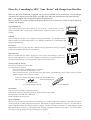
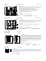
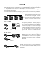
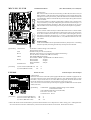
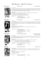
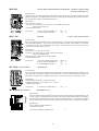
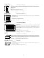
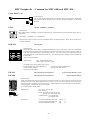
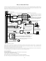
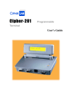
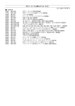
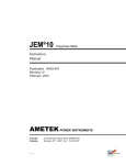
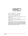
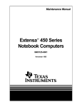
Table of Contents
MPC-68K System Construction Example ....................................................................... 2
MPC-68K Series ~16-Bit CPU Controller ~ ................................................................. 4
MPC-LNK ............................................................................................................................ 8
MPC-816 Series ~ 8-Bit CPU Controller ~ ................................................................ 10
MPC Peripherals ~ Common for MPC-68K and MPC-816 ~.................................. 14
How to Deal with Noise .................................................................................................. 15
FTMW (FTM – Work Bench) ......................................................................................... 16
List of Compatible Connectors ...................................................................................... 16
Request to Our Customers .............................................................................................. 17
Please Try Controlling by MPC. Your “Device” will Change from That Day.
MPC uses the latest flash ROM! Equipped with an on-board ROM-conversion function, it is a board-type
controller with complete protection against noise (RS-232C and pulse generation are also photo-isolated).
MPC is also equipped with complicated commands and functions.
However, multi-axis control is enabled immediately after the power is turned on, as there is simple support by
a BASIC-like language.
Programming Device
Your personal computer such as PC98, DOS/V, etc. can be used as is. The file format is in easilyeditable ASCII data, which is supported by a terminal software “FTM” (its Windows version is also
available).
Language
This is a BASIC-like interpreter. Even a beginner can program immediately. Also, abundant commands
make it possible to write complicated applications. Also, although it’s BASIC-like, it’s a full-featured product
equipped with multitasking.
I/O Control
Its dedicated I/O realizes 24~768-point control. Both bit processing and parallel processing are supported
by dedicated commands, which allows a wide application.
Pulse Generation
MPC-816 and MPC-68K can control a stepping/servo motor of up to 50 and 400 kpps, respectively.
Instead of simple support for one axis at a time, commands are prepared for even an XY-orthogonal 4-axis
robot that includes palletizing. It can also deal with S-shape acceleration/deceleration.
Necessary Things for Startup
The following are initially necessary to MPC.
To be prepared by the customer:
A personal computer (PC98DOS, DOS/V, or Windows)
DC24V power (necessary for making MPC work)
Wiring sockets and contacts, a pressure-attaching tool (JAE product) or PS-50SEN-D4T1-1D, etc. Other necessary connectors
depend on products. Please refer to the manual.
Connectors ,socket ,and contacts (in the case of individual wires)
Control contacts
Pressure-attaching tool
030-51304-001(JAE)
For socket housing(PS-D4C50)
CT150-1-PSSF(JAE)
Our Products
Cable set (for PC98 and DOS/V compatible machines)
FTM terminal software for programming (for PC98, DOS/V machines, and Windows)
Main unit (must contain MPC-816 or MPC-68K)
Manual (attached at the first purchase)
Selection Guideline
MPC-816 series are inexpensive and compact for controlling up to 4 axes within 50 kpps and I/O 200 points. MPC-68K can be used for
controlling multiple axes within 40 kpps and I/O 500 points. Both of them are equipped with RS-232C for the user. Also, MPC-68K can
support complicated character processing by a high-level language. The MPC-816 interpreter (TNYFSC®) is a simple language, and the
MPC-68K interpreter (ADVFSC®) is a full-featured BASIC language (computation is limited to 4-byte integers). Also, we have MPC683 for large-scale high-speed processing and floating-point computation.
-1-
MPC-68K System Construction Example
MPC is a BASIC-like multitasking
interpreter, which is a FA controller
capable of multiple-axis and
communication processing as well as
I/O of course.
[Cable DOS/V 98]
RS-232C CH1
Products of ACCEL are inside [ ].
[MPC-68K (FSC)]
Main CPU
RS-232C 3CH
[Terminal software FTM, FTMW32]
Programming & teaching personal
computer
NEC 9801
Toshiba J3100
IBM PC/AT compatible machines
Windows 95, NT
RS-232C CH2
Touch panel
RS-232C CH0
Image processing device
4-axis robot
X
[MPG-405]
4-axis PG board
MAX 400 Kpps
Origin port
Y
X
Y
U
Z
Origin SW
Encoder Z phase
[MPG-405]
Y
U
X
XY table
Origin SW
Encoder Z phase
Material removal/supply
elevator
Z
X
[MPG-405]
X
Origin SW
[MIP-048]
Input dedicated
48 points
Maximum 8 boards
Encoder Z phase
Y
Input
X
[MOP-048]
Output dedicated
48 points
Maximum 8 boards
Output
[RACK-68K]
6 slots
Maximum 3 boards
Connecting possible
AC servo motor drivers
Mitsubishi MELSERVO-J series,
Matsushita MSD series, etc.
Difference movement input.
Stepping motors
Oriental UPD series, etc.
Photocoupler input.
Device image
4-axis robot + image processing
XY table
Material removal/supply elevator
Transportation conveyer
Liquid crystal touch panel, etc.
Chip mounter, inserter, assembly
adjustment device, etc.
* Connecting two slots or more may require a terminator-compatible board MBK-68K.
DC 12V ~ DC 24V is supplied to each board of the MPC series, RS-ISO, and PIF-422.
For the details of MPC program and hardware, see the “USER’S MANUAL”. Consultation on the MPC construction is available. Feel
free to contact us.
-2-
-3-
MPC-68K or MPC-684
MRS-402
MPC-SLINK
RS422
68K
BUS
RS-232
RS485(422)
! SLINK1
* As an option function of MRS-402, WEB,
FTP, and TCP/IP are planned to be supported
via Ethernet RS converter.
Ethernet (TCP/IP) <=> RS Converter
SLINK2
! Display during program execution (7SEG) ! Communication with RS-232 function ! Wiring-saving system, SLINK
! Touch panel support
* TCP/IP support
(Two 128-point modules loaded)
* User customizable
MBK-68
Connected with MBK-68 via RS422 at 38.4 kbps.
Using the standard ON/OFF command supporting
68K, applications utilizing a touch panel
can be constructed
! 98/9 Digital GP70 series supported
Touch Panel Display
Butaface
! Supported
MPC-68K Expandability
MPC-68K Series ~16-Bit CPU Controller ~
MPC-684
High-Speed CPU Board
4 Outputs, 8 Inputs
[Characteristics]
This is a high-speed CPU board equipped with two RS-232C channel. By its installed
interpreter (ADVFSC®), programming is possible in a BASIC-like environment. MPC-683
supports an execution speed more than twice as fast as 68K, and floating-point computation.
(1)
(2)
[Specification]
Power source: DC 12V~24V battery retained for 5 years (w/o external power supply at
room temperature).
CPU: MC68340 20M clock. 4M SRAM*2 + 4M FROM*2.
Control I/O: 8-point photocoupler input (4-point open collector output).
RS232c: 2CH
Self-consumed current: 500 mA (1A power source installed)
[Option] MC688XXFN-25 Coprocessor (for floating point calculations)
[Accessories]
MPC-68K
(1) Power connector (H4P-SHF-AA)
(2) Contacts (BHF-001T-0.8SS)
Main CPU Board
JST
JST
*1
*4
4 Outputs, 8 Inputs
[Characteristics]
This is a CPU board equipped with two RS-232C channels. By its installed interpreter
(ADVFSC®), programming is possible in a BASIC-like environment. In spite of its
compactness, it is equipped with two 4M-bit flash ROMs, and its program area of about
10000 steps can be used by an actual machine without any procedure such as ROM conversion
or compiling. It can also be used as a pulse generator by itself. Its bus is C-bus-based, so an
I/O board for 98 can also be directly used.
(1)
CEP-041
MPC68K
(2)
ACCEL CORP.
[Specification]
Power source: DC 12V~24V battery retained for 5 years (w/o external power supply at
room temperature).
CPU: TMP68301F-16 16 MHz. 1M SRAM*4 + 4M FROM*2.
Control I/O: 4-point open collector output. 8-point photocoupler input.
RS232c: Photoisolated, user 2CH.
Self-consumed current: 250 mA (1A power source installed)
[Accessories]
MPG-405
(1) Power connector (H4P-SHF-AA)
(2) Contacts (BHF-001T-0.8SS)
High-Speed S-Shape Acceleration/Deceleration PG Board (400K)
(3)
(1)
(2)
JST
JST
*1
*4
4-Axis Output, 8-Origin Input
[Characteristics]
This is a dedicated pulse-generation board equipped with the maximum pulse rate of 400
kpps (two-axis linear interpolation). It is an upper-compatible board that can replace MPG68K. Because it uses dedicated pulse generation (except GO, RM, DEFTBL, XPLS, and
WPLS), DDA computation, and counter IC, high-speed pulse generation and arc interpolation
have become possible. The arc interpolation is up to 200 Kpps. Also, because it is equipped
with an S-shape acceleration/deceleration function, vibration prevention of the device is also
effective.
[Specification]
Power source: DC 12V~24V battery retained for 5 years (w/o external power supply at room
temperature).
CPU: TMP84C015BF, KM3701, X3202, etc.
Pulse output: 4-axis/RS422 specification (photoisolated).
Consumed current: 180 mA
[Accessories]
(1) Power connector (H4P-SHF-AA)
(2) Contacts (BHF-001T-0.8SS)
(3) Connector (HIF-3BA-16D-2.54R)
-4-
JST
*1
JST
*4
Hirose *1
MPG-68K
PG Board (100K)
4-Axis Output, 8-Origin Input
[Characteristics]
This is a board equipped with 4-axis simultaneous-control pulse generation. By an interpreter
(ADVFSC®) installed on MPC-68K, programming is possible in a BASIC-like environment.
The maximum pulse rate is 100 kpps (for 3-axis simultaneous interpolation). One MPC-68K
can support about three MPG-68K boards. If a power source unit (MPS-324) is added, about
six boards can be supported.
(3)
(1)
(2)
[Specification]
Power source: DC 12V~24V (for I/O control). Battery retained for 5 years (w/o external
power supply at room temperature).
Pulse output: 4-axis/RS422 specification (photoisolated).
CPU: TMP68301F-16 16MHz. 1M SRAM*2 + 1M PROM*2.
Control I/O: 4-axis output, 8-point origin sensor input.
Consumed current: 150 mA
[Accessories]
MOP-048
(1) Power connector (H4P-SHF-AA)
(2) Contacts (BHF-001T-0.8SS)
(3) Connector (HIF-3BA-16D-2.54R)
JST
*1
JST
*4
Hirose *1
48-Point Transistor Output Board
48 Outputs
[Characteristics]
This is a dedicated output board equipped with 48-point output. Each output is equipped with
an LED monitor. The output interface is an open collector output using a TD62004, where the
control current is 100 mA per one output. Therefore, relays and compact solenoids for airpressure control can be connected as they are. Also, because it functions even with 5 V, it can
be used as a TTL output interface. Addresses can be specified by DIP switches (full decoding).
MPC-68K supports up to eight MOP boards.
(1)
ACCEL CORP
CEP-013B
MOP-048
(2)
[Specification]
Power source: DC 5V~24V (for I/O control). 48-point open collector output.
Consumed current: 80 mA
[Accessories]
MIP-048
(1) Power connector (H4P-SHF-AA)
(2) Contacts (BHF-001T-0.8SS)
JST
JST
*1
*4
48-Point Photocoupler Input Board
48 Inputs
[Characteristics]
This is a dedicated input board equipped with 48-point input. Each input is equipped with an
LED monitor. The input interface is a photocoupler input using a TLP-521, where the control
current is 2 mA per one input. Also, because it functions even with 5 V if the resistor array is
exchanged, it can be used as a TTL input interface. Addresses can be specified by DIP switches
(full decoding). MPC-68K supports up to eight MIP boards. MIP-048 is equipped with a
resistor socket for two-line sensor compatibility.
(1)
(2)
[Specification]
Power source: DC (5V) 12V~24V (for I/O control). 48-point optocoupler input.
* If used with DC 5V, the resistor array needs to be replaced.
Consumed current: 30 mA
[Accessories]
(1) Power connector (H4P-SHF-AA)
(2) Contacts (BHF-001T-0.8SS)
JST
JST
*1
*4
* Current values indicate standard consumed current TYP values. Please keep 20~50 % room in designing.
* Current values indicate consumed current of the internal DC 5V power source, and the maximum current values with all I/Os
ON for the I/O boards.
* [] Current values indicate externally-supplied DC 24V current, and the minimum current values with all I/Os OFF.
-5-
IOP-048
24-Point Photocoupler Input Board / 24-Point Transistor Output Board
[Characteristics]
This is a dedicated input/output board equipped with 24-points for each input and output.
Each input/output is equipped with an LED monitor. The input and output interfaces have
equivalent specifications with MOP and MIP, respectively.
(1)
(2)
MPG-3202
[Specification]
Power source: DC (5V) 12V~24V (for I/O control).
24-point optocoupler input. 24-point open collector output.
* If used with DC 5V, the resistor array needs to be replaced.
Consumed current: 50 mA
[Accessories]
(1) Power connector (H4P-SHF-AA)
(2) Contacts (BHF-001T-0.8SS)
JST
JST
*1
*4
S-Shape-Compatible PG Board & Encoder Counter Board
(2-Axis)
[Characteristics]
A general-use PG board loaded with pulse generation and counter ICs that can support
two axes. Interface of the pulse output and the encoder is RS-422 specification that can
deal with high-speed (1M pps) pulse output and input. The mounted PGIC is X3202 that
can deal with the S shape and is equipped with various intelligent functions.
MPG-3202CEP-075
ACCELCORP.
(1)
(2)
MRS-402
[Specification]
Power source: DC 12V~24V
Pulse output: Differential pulse output *2 axes / RS-422 specification * 2 axes
Encoder input: Differential pulse input (A-B phase encoding) * 2 axes
[Accessories]
(1) Power connector (H4P-SHF-AA)
(2) Contacts (BHF-001T-0.8SS)
JST
JST
*1
*4
RS-232 Expansion Board
RS-232C
[Characteristics]
This is a 2CH RS-232C(RS-485) expansion board, of which up to two can be installed. Because
it is an intelligent design by dual-port RAM, it does not provide burden on the CPU. The
interface is photo-isolated, and the modem control terminal is RTS×CTS only. Software support
is dealt with in a similar way to the standard commands and functions, assigned to #3~#6.
(1)
MRS-402 CEP-059
ACCEL CORP.
MPS-324
(2)
[Specification]
RS-232 standard interface. Input buffer 1K byte.
Consumed current: 50 mA
[Accessories]
(1) Power connector (H4P-SHF-AA)
(2) Contacts (BHF-001T-0.8SS)
3A Power Source Board
(3)
(1)
(2)
JST
JST
*1
*4
4(8)-Point Relay Output
[Characteristics]
Although MPC-68K is equipped with a 1 A power source, when the system scale becomes
large, it becomes short of current. In a large-scale system, this MPS-324 is used. The
supplied current is 3 A. Also, MPS-324 is equipped with a 4-point relay output circuit (4
more relays can be further added). A PC98-bus compatible DC ±12 V DC-DC converter
can be installed on the board. By this, peripheral boards for 98 requiring ±12 V power
source can be used.
[Specification]
Power source: DC 24V±10%. 4(8)-point relay output.
Consumed current: 3 A supply
[Accessories] (1) Power connector (H4P-SHF-AA)
(2) Contacts (BHF-001T-0.8SS)
(3) Connector (HIF-3BA-34D-2.54R)
-6-
JST
*1
JST
*4
Hirose *1
MBK-68
Multifunction Board
[Characteristics]
MBK-68 is a function-addition board of MPC-68K and MPC-683. The following functions
are added. Please insert this board to the right end of the rack (on the opposite side of CPU).
Bus terminator is added, making a large-scale system more reliable.
Display of the statement number during execution is added. 7 SEG display.
Digital Corp GP70 Series can be connected. Other supports are under evaluation.
Large-scale data arrays can be dealt with by 68K and 683 interpreters.
Battery backup function is added to MPC-683.
MBK-68K CEP -064A
MPC-SLINK
RS-422 * 2CH
(1)
[Specification]
Consumed current: 200 mA. Photo-isolated RS422.
(2)
[Accessories]
(1) Power connector (H4P-SHF-AA)
(2) Contacts (BHF-001T-0.8SS)
Slink I/O Board
JST
JST
*1
*4
MAX 256 * 2 (I/O)
[Characteristics]
MPC-SLNK is a board which supports the Sanks SLINK system. It is equipped with two
host module made by Sanks as a default (maximum 512 points). Also, up to two MPCSLNK boards are supported by 68K. Assigned I/O area starts at 2000.
MPC-SLINK CEP-069
ACCEL CORP
[Specification]
Consumed current: 200 mA (per module). SLINK specification follows that of Sanks.
(1)
[Accessories]
(1) Housing (5557-08R)
Molex *2
[Compatible parts] Please purchase upon necessity.
Pressure-attaching tool (57027-5000 (Molex))
Extracting tool (57031-6000 (Molex))
Contacts (5556TL (Molex))
Housing (5557-04R (Molex))
RACK-68K6
RACK-68K3
6-Slot Rack
3-Slot Rack
[Characteristics]
These are board racks dedicated to MPC-68K. Their design is highly condensed with
a board pitch of 20 mm. A mounting flange attached as a default is attachable toward
any of the top, bottom, front, and back direction. RACK-68K has a 3-slot and a 6-slot
version. Also, by a connection kit sold separately, up to three racks can be connected,
constructing a system with maximum of 18 slots. The 6-slot rack can be arranged on
either the left or the right side, but the 3-slot rack can only be arranged on the right side.
Because the bus construction is based on PC98 I/O bus, various kinds of commercial I/
O boards for 98 can be used.
[Specification]
PC98 I/O bus standard, 20 mm pitch, 6 slots.
[Accessories]
ADP-68K
Screws (M3*4)
Screws (M3*12)
Rack assembly use
For attaching the bus
* 16
*4
Connection Kit
[Characteristics]
This is a connection kit for said racks. By this, RACK-68K can be expanded up to 18 slots. The components are spacers
and a 50-pin flat cable. Only the I/O bus signal is connected by the 50-pin flat cable. By this connection kit, racks can be
mechanically and electrically (conduction-wise) connected to an arbitrary size, but the reliability will decrease if the bussignal width exceeds 50 cm.
[Accessories] Screws (M3*4)
Spacers (SP-17)
*8
*4
-7-
MPC-LNK
MPCLNK is a network board with an objective of sharing memory data and bit-unit information. By using MPCLNK, connected equipment (personal
computers and MPC-68K) can share 249-byte memory. Also, because a function is included for transferring data by block to a specified address,
individual communications that used to be performed by RS-232C etc. are supported together by MPCLNK. The number of connectable units is up
to 16. When MPCLNK and LNK-048 are combined, one unit of MPCLNK and up to 15 units of LNK-048 are connectable.
The response speed is within 10 msec for transferring a shared variable from #1 to any other, and is the number of connection * 10 msec for changing a shared
variable of #2-#15 except #1 or for the input status of LNK-048 to be returned to #1. In the case of up to five-unit connection which is a default factory shipout condition, the response speed is within 50 msec.
As for the distance of the communication cable, because it is based on RS-485 standard, the connection will have no problem up to several hundred meters.
Also, the communication interface is isolated by a pulse transformer, preventing noise trouble etc. that occurs when used by different power sources.
Connection Method
J2
J3
J2
SP10
shorted
J3
J2
J3
J2
SP10
open
SP10
open
J3
SP10
shorted
Because MPCLNK adopted an interface based on RS-485, it
can be easily connected via twisted-pair cables. Two connectors
and a short pin for a terminator belong to MPCLNK, and they
are connected as in the figure. What should be kept in mind is
for the connection to be in a cascade as in the figure and to set
the terminator ON (the short pin is shorted) for the MPCLNKs
at the ends.
PC (AT, 98) + LNK-048
This is a remote IO for a personal computer. One LNK-048 is equipped with
24-point input and 24-point output, and can perform reading of input from
the host side and control of the output port. The host needs one MPCLNK,
and the I/O unit and MPCLNK are connected via a twisted-pair cable. Because
communication is done through an RS-485 interface, connection of plural
LNK-048 is simple by multiple-drop bus connections of a twisted pair.
Control and reading of the IO are performed via the UMB area of the personal
computer (this is because MPCLNK works as a memory installed in the UMB
area). Writing into the UMB area is reflected as is by the output port of
LNK-048, and the input content of LNK-048 is reflected as is by the specified
memory of the UMB. Therefore, the I/O can be directly controlled using
application software for DOS/WINDOWS etc.
MPC- LNK
LNK- 048
E
A
A
O
PC- LNK
LNK- 048
Twisted pair
MPC-68K + LNK-048
LNK-048
CE P -0 4 1
MPC-LNK
LNK-048
MPC-68K
LNK-048 is a remote IO of MPC-68K. One LNK-048 is equipped with 24point input and 24-point output, and can perform reading of input from the
68K side and control of the output port. The host needs one MPCLNK, and
the I/O unit and MPCLNK are connected via a twisted-pair cable. Because
communication is done through RS-485 interface, connection of plural LNK048 is simple by multiple-drop bus connections of a twisted pair. For control
and reading of IO, the IO commands such as ON/OFF, SW(), etc. of MPC68K are available.
Twisted pair
LNK-048 + LNK-048
LNK- 048
LNK- 048
By using LNK-048 one on one, the I/O condition can be transmitted as it is to a
distant place. The 24-point input content to one is reflected by the output of the
other. Connection of LNK-048 is by one twisted pair, withstanding even a distance
of several hundred meters (in the case of an RS-485 standard cable). Also, if the IO
link destination is fixed, two or more LNK-048 can be IO-connected (customization
will be necessary).
-8-
MPC-LNK, PC-LNK
Communication Board
MPCLNK
CEP-028C
ACCEL CORP.
(1)
(2)
(1)
(2)
[Specification] Communication
[Characteristics]
MPC-LNK (PC-LNK) is a data network connecting our MPC-68K, NEC PC98 series, and
DOS/V machines. Unlike networks by other specifications, it does not let the host generate
interruptions or consume system memory. MPC-LNK itself becomes a RAM board connected
via communication, both the connected 68K and personal computer having shared variables
usable in common.
The connection interface uses RS-485 (750 kpps SDLC standard), where a network can be
easily constructed by a twisted-pair multiple drop (the maximum connection length is 1.2
km according to the RS-485 specification). MPC-LNK can be utilized not only as a pure
68K network but also as a data exchange network for personal computers using libraries.
Shared variables
These are common variables of 249 bytes which all MPC-LNK can refer to. Shared variables
are refreshed every 24 sec and can be changed or referred to at real time. The content set by
the #1 station circulates to the whole every 10 msec, and the content changed by the #2 or
latter station is reflected by the whole every n * 10 msec (n is the number of MPC-LNKs
connected to the network, whose default value is 5). Also, 68K deals with them as 125 wordtype variables.
Mail forwarding
All the connected MPC-LNKs can perform block transfers by 250-byte units. In forwarding
mail, the receipt status, forwarding, and read-out by the recipient can be confirmed.
RS-485/SDLC standard 750 kpps. SN75176B used.
Pulse transformer isolated.
Shielded twisted pair to be used (60 nF/km)
MPCLNK: 68K system bus / PC-98 expansion bus standard (full decoding).
PC-LNK: ISA bus. Installed in the UMB area as memory.
68K: 1000H, 2000H fixed (I/O area).
PC98 / DOS/V: C0000H~ (expanded ROM area 0~BFFH exclusive).
Shared variables
249 bytes
Send-mail buffer
250 bytes
Receive-mail buffer
250 bytes
150 mA
Cable
Bus I/F
Address
Memory
Consumed current
[Accessories]
(98 C-Bus Standard) / PC-LNK (ISA)
(1) Power connectors (H4P-SHF-AA) JST
(2) Contacts (BHF-001T-0.8SS)
JST
LNK-048
*2
*6
Remote IO Unit
24-Point Output / 24-Point Input
[Characteristics]
Remote IO can be used in a MPC-68K system equipped with MPCLNK. LNK-048 is equipped with 24point input and 24-point output, and can monitor the status of a sensor distant from the host or control
the actuator. Also, if used as an IO etc. for a control BOX of an apparatus, because the host and LNK048 can be connected via a twisted pair, it will also become a wiring-saving system.
Also, it can be used as a remote IO of a personal computer equipped with MPCLNK or PCLNK (PCM95W03, with a case).
[Specification]
(2)
Communication: RS-485/SDLC standard 750 kpps. SN75176B used.
Pulse transformer isolated.
Cable: Shielded twisted pair to be used (60 nF/km)
Power source: DC 24V ± 10%
Consumed current: 150 mA
(3)
(1)
[Accessories]
(1) Power connector (H4P-SHF-AA)
(2) Power connectors (H3P-SHF-AA)
(3) Contacts (BHF-001T-0.8SS)
JST
JST
JST
*1
*2
*10
* MPC-LNK model will be modified due to production discontinuation of its component ICs within coming years. Although the new
series and old series cannot be combined, they can be used in the same software environment. Please take note of this.
-9-
MPC-816 Series ~ 8-Bit CPU Controller ~
MPC-816K
Main CPU Board
8 Outputs, 16 Inputs
[Characteristics]
This is a CPU board equipped with the I/O for control. By its installed interpreter (TNYFSC), programming is possible
in a BASIC-like environment. In spite of its compactness, it is equipped with 2M-bit flash ROM, and its program area
of about 2000 steps can be used without any procedure such as ROM conversion or compiling. Also, a user RS-232C
(isolated) is equipped, making it applicable to communication-involving use.
(3)
[Accessories]
MPG-916F
CEP-080
ACCEL CORP.
(1)
[Specification]
Power source: DC 12V~24V battery-retained for 7 years (w/o external power supply at room temperature).
CPU: KL5C80A16, 7.37 MHz, 1M SRAM + 2M FROM.
Control I/O: 8-point open collector output, 16-point photocoupler input.
Self-consumed current: 110 mA (380 mA power source installed)
(2)
MIF-816K
(1) Housing (PS-D4C50)
(2) Power connector (H4P-SHF-AA)
(3) Contacts (BHF-001T-0.8SS)
JAE
JST
JST
*1
*1
*4
Bus Interface Board
8 Outputs, 16 Inputs
[Characteristics]
This is the first expansion board of MPC-816. It is a bus interface of expanded I/O: MIO-816 and also equipped with
the control I/O at the same time. Also, a 16-pin connector J5 becomes a pulse output port if the Z version is selected on
MPC-816, enabling simple control of a pulse motor, etc. Also, MPC-SET (EX) is the set of MPC-816 and MIF-816
being packed in a case.
CEP-056 MIF-816K
ACCEL CORP
[Specification]
Power source: DC 12V~24V (for I/O control).
Control I/O: 8-point open collector output, 16-point photocoupler input, 4-axis pulse output port.
Consumed current: 30 mA
(1)
[Accessories]
(3)
(2)
(4)
(5)
MIF-816AD
(1) Housing (PS-D4C50)
(2) Power connector (H4P-SHF-AA)
(3) Contacts (BHF-001T-0.8SS)
(4) Connector (HIF-3BA-16D-2.54R)
(5) Spacers (MSPLS-7)
JAE
JST
JST
Hirose
*1
*1
*4
*1
*4
Bus Interface Board with AD/DA
8 Outputs and 12 Inputs
CEP-071 MIF-816AD
ACCEL CORP
3CH A/D 1CH D/A
[Characteristics]
This is the first expansion board of MPC-816 and has almost the same specification with MIF-816. Differences from
MIF-816 are that it is equipped with a 12-bit A/D and D/A converter and that J5 has no ZCW and ZCCW output. It is
best for small-scale analog test output circuits.
(2)
(1)
[Specification]
Power source: DC 12V~24V (for I/O control). DC 5V (for A/D and D/A). Internal V can be also used.
Control I/O: 8-point open collector output. 12-point photocoupler input.
3-axis pulse port (w/o ZCW and ZCCW). 3-CH analog input.1-CH analog output.
Consumed current: 260 mA (150 mA if A/D and D/A are externally supplied.)
[Accessories]
(3)
MBK-816
(1) Power connector (H4P-SHF-AA)
(2) Contacts (BHF-001T-0.8SS)
(3)Spacers (MSPLS-7)
JST
JST
*1
*4
*4
Touch-Panel Interface Board
RS-422(485) 2CH
ACCEL CORP.
CEP-072A MBK-816
[Characteristics]
This is an I/F board for a touch panel display for MPC-816. It is compatible with Memo-Link of Digital Corp. as of
March 99, and it can be interfaced with the panel by using only ON/OFF/SW() commands from the MPC-816 side.
[Specification]
Power source: DC 12V~24V (for panel communication)
Control I/O: RS-422(485) 2CH
Consumed current: 200 mA
[Accessories]
(1)
(2)
(1) Power connector (H4P-SHF-AA)
(2)Contacts (BHF-001T-0.8SS)
-10-
JST
JST
*1
*4
MPC-816XC
Compact Controller
8 Outputs, 16 Inputs
[Characteristics]
This is a single MPC-816 stored in a case. Please use it when you use one CPU board installed directly in an apparatus.
Refer to MPC-816K for the specification details.
(1) Housing (PS-D4C50)
(2) Power connector (H4P-SHF-AA)
(3) Contacts (BHF-001T-0.8SS)
JAE
JST
JST
*1
*1
*4
MPC-816XC
[Accessories]
(1)
(3)
(2)
MPC-SET (EX)
Compact Controller
16 Outputs, 32 Inputs
[Characteristics]
This is a combination of MPC-816 and MIF-816 stored in a case. It can be used also as a controller with 16-point
output and 32-point input. Also, because simple pulses can be generated (max 60 Kpps) from J5 of MIF, it can be used
also as a positioning device.
Refer to MPC-816K and MIF-816K for the specification details.
FLASH
Slide-in Brain ACCEL
MPC-SET(EX)
[Accessories]
(1) Housing (PS-D4C50)
(2) Power connector (H4P-SHF-AA)
(3) Contacts (BHF-001T-0.8SS)
(4) Connector (HIF-3BA-16D-2.54R)
JAE
JST
JST
Hirose
*2
*1
*4
*1
(3)
(1)
(2)
(4)
MIO-816K
Expanded I/O Board
8 Outputs, 16 Inputs
[Characteristics]
This is an expanded I/O board for MPC. Expansion is possible up to 11 boards. Because all the I/Os are isolated by
photocouplers, noise resistivity is high, and each I/O can be used by power sources different from the others. Also, by
installing a J2 connector by the user, a small-scale system can be constructed in combination with MPC-816 without
using MIF-816.
CEP-057 MIO-816K
ACCEL CORP
[Specification]
Power source: DC 12V~24V (for I/O control).
Control I/O: 8-point open collector output, 16-point photocoupler input.
Consumed current: 50 mA.
(1)
[Accessories]
(3)
(2)
MIO-248K
(1) Housing (PS-D4C50)
(2) Power connector (H4P-SHF-AA)
(3) Contacts (BHF-001T-0.8SS)
JAE
JST
JST
*1
*1
*4
Expanded I/O Board
24 Outputs, 8 Inputs
ACCEL CORP.
MIO-248K CEP-058B
[Characteristics]
This is an expanded I/O board for MPC. Expansion is possible up to 11 boards. Because all the I/Os are isolated by
photocouplers, noise resistivity is high, and each I/O can be used by power sources different from the others. Also,
because it is designed to be compatible with DC 5V, it can also be used as a TTL interface. When used with 5V, a
resistor array is added to the SIP socket.
[Specification]
Power source: DC 5V~24V (for I/O control).
Control I/O: 24-point TLP627 photocoupler open collector output,8-point photocoupler input.
Consumed current: 110 mA.
(1)
(2)
[Accessories]
(3)
(1) Housing (PS-D4C50)
(2) Power connector (H4P-SHF-AA)
(3) Contacts (BHF-001T-0.8SS)
-11-
JAE
JST
JST
*1
*1
*4
MPG-301
One-Axis Pulse Generation Encoder Counter Board
1M PPS 1-axis pulse output
1M PPS encoder input, etc.
[Characteristics]
MPG-301 is a pulse-generation multifunction board which is loaded with one Kyopal X3202 and let MPC816 directly
operate the IC register. It is capable of flexible control such as changing pulse rate during pulse generation, referring to
the present position, S-shape acceleration/deceleration, etc.
[Specification]
Power source: DC 12V~24V
Control I/O: One-axis RS422 driver pulse output. One-axis RS422 encoder input.
Z-phase input, limit input, etc.
Consumed current:150 mA
CEP-070A MPG-301
ACCEL CORP.
(2)
(1)
[Accessories]
MPG-303
(1) Power connector (H4P-SHF-AA)
(2)Contacts (BHF-001T-0.8SS)
JST
JST
*1
*4
PG Board
2-Axis + 2-Axis Pulse Generation
[Characteristics]
This is a pulse-generation board based on 2-axis linear interpolation. It is supported by the commands of TNYFSC
interpreter installed in MPC-816. Also, MPC-816 supports three MPG-303 boards. In the standard P version, MODE
5 and MODE 6 are used. The maximum pulse rate is 50 kpps. As for the output axis, two axes can be used at an
exclusive time from either the XY or ZU axis.
[Specification]
Power source: DC 5V~24V (for I/O control).
Control I/O: 4-axis pulse output port (photo-isolated, open collector).
8-point origin-returning sensor.
Maximum pulse rate: 50 kpps CW/CCW2 pulse method.
Consumed current: 80 mA
(1)
(3)
(2)
MCT-801
[Accessories]
(Conserved Item)
(1) Connector (HIF-3BA-16D-2.54R)
(2) Power connector (H4P-SHF-AA)
(3) Contacts (BHF-001T-0.8SS)
Hirose *2
JST
*1
JST
*4
Counter Board
[Characteristics]
This is a 24-bit up-down counter equipped with an encoder/decoder. It deals with both encoder input and pulse input.
The input interface is optoisolated. Although a rotary encoder with 12V power is assumed in the ship-out setting, it can
deal with DC 5V and DC 24V by changing the resistor array. Up to two MCT-801s can be used in one system.
[Specification]
A-B-phase phase encoder input / Up-down pulse input
Compatible with 500 kpps. Power source: DC 5V ~ DC 24V
Consumed current: 20 mA
[Accessories]
(1)
CARD
(Conserved Item)
MEMORY
MCD-001
(1)
(1) Connector (PS-16SEN-D4P1-1)
JAE
*1
Data Memory Card
[Characteristics]
This is an interface board for supporting a memory card (32 kbyte) made by Fujisoku. When MCD-001 is used,
an array of 10921 is extended as M() on the memory card. By utilizing this numerical data area, switching is
performed of the model that used the IC card, storing a large amount of data, etc. Also, MCD-001 is equipped
with four digi-switches, enabling a read-out of values by the commands. MPC-816 supports one MCD-001.
[Specification]
IC card: Made by Fujisoku (BS32D1-A)
Consumed current: 10 mA
[Accessories] (1) Memory card (BS32D1-A)
-12-
*1
RACK-SET (A)
4-Board Construction Rack Set
[Characteristics]
This is a rack set for MPC-816. It deals with a 4-board construction system. MPC-SET (A) is a rack set with MPC-816
and MIF-816 added.
[Construction]
RACK (A) main body, BUS board A, Rack flange.
[Accessories] Screws (M3 * 4)
RACK-SET (B)
For assembling rack
*16
8-Board Construction Rack Set
[Characteristics]
This is a rack set for MPC-816. It deals with an 8-board construction system. MPC-SET (B) is a rack set with MPC816 and MIF-816 added.
[Construction]
RACK (B) main body, BUS board B, Rack flange.
[Accessories]
Screws (M3 * 4)
RACK-SET (C)
For assembling rack
*16
16-Board Construction Rack Set
[Characteristics]
This is a rack set for MPC-816. It deals with a 16-board construction system. Please be careful
about the power source capacity for a 16-board full system. The current-supply capacity of MPC816 is up to 380 mA including 816. If a power shortage is anticipated, please remove JP1 on
MPC-816 and supply DC 5V directly to the bus board. MPC-SET (C) is a rack set with MPC-816
and MIF-816 added.
[Construction]
RACK (C) main body, BUS board A, Rack flange.
[Accessories]
ADP-325
Screws (M3 * 4)
For assembling rack
*20
Metal Fittings for Compact Boards
[Characteristics]
These are metal fittings for compact boards with a PCB width of 70 mm. A commercial I/O board for Z80 can be inserted
into the RACK by these. As for the way of attaching it, remove the guide rail, install the metal fittings, and put back the
guide rail.
[Construction]
U-shape metal fittings *2, Fitting machine screws *4.
Flange H / Flange D
Flange H
Flange D
Metal Fittings
[Characteristics]
Metal fittings for MPC-SET (EX) and MPC_816XC. The H type is for a back-face installation, and the D type is for
a bottom-face installation.
[Construction]
Metal fitting *1, Machine screws *2.
-13-
MPC Peripherals ~ Common for MPC-68K and MPC-816 ~
Cable DOS/V 98
[Characteristics]
This is a cable of our company brand to connect MPC and a personal computer. Although the
basic cable is for DOS/V, because a 25-pin conversion connector is included, it can also be used
for PC98.
FTM
(FTM98 / FTMDOSV / FTMWIN)
[Characteristics]
MPC terminal software “FTMW32”, 816/68K command references, Communication program development support tools, etc.
are included.
[Construction]
Setup Disk (3.5” 1.44 MB format).
* Other than these, there are FTM versions for NEC98DOS, DOS/V, and English Windows. Please refer to our Business or
Technical Department.
IOD-024
I/O Relay Box
CEP-025
ACCEL
[Characteristics]
Because the I/O connector of MPC is compact and has high density, wiring work in a large-scale system is troublesome,
and because there is no display of the I/O, debugging is laborsome. IOD-024 connects to the I/O connector of MPC via
a flat cable, and branches it point by point to a relay connector. Also, because each point is equipped with an LED,
wiring debugging and system maintenance become easy. Also, interfacing a sensor containing a two-line amplifier can
be done easily.
(With a case PCML-95W02)
[Specification]
Input: 26-pin/50-pin flat cable.
Output: Molex 5557-04R + 5556TL
[Compatible parts] Please purchase upon necessity.
Pressure-attaching tool (57027-5000 (Molex))
Contacts (5556TL (Molex))
Housing (5557-02R (Molex))
PIF-422
PIF-400
Pulse-Signal Conversion Interface
(Conversion into RS-422 or TTL)
Pulse-Signal Conversion Interface
(DC 24V Open Collector)
[Characteristics]
In MIF-816 and MPC-68K, the pulse-signal output is not isolated. Therefore, if a driver is directly connected, noise may
cause the controller to stall. When a high-noise driver such as an AC servo is connected, please use one of the above
conversion interfaces depending on the kind of interface. Although PIF-422 is an RS-422 output, if an SG terminal is
connected together, it can deal with 5V TTL-level signals.
(A case sold separately: PCML-60S02)
CEP-027 PIF-422
ACCEL
[Specification]
Power source: DC 12V~24V
Input: TLP-552
Output: SN75158P (for 4 axes) (PIF-422)
DC 24V open collector (PIF_400)
Consumed current: [70 mA] (PIF-422)
[30 mA] (PIF-400)
[Accessories]
(1) Connector (HIF-3BA-16D-2.54R)
(2) Power connector (H4P-SHF-AA)
(3) Contacts (BHF-001T-0.8SS)
(1)
(2)
Extracting tool (57031-6000 (Molex))
Housing (5557-04R (Molex))
(3)
-14-
Hirose
JST
JST
*2
*1
*4
How to Deal with Noise
Control involving position determination control internally deals with signals of several msec. Because this signal is at a similar level to a
noise signal, no matter what control device is used, reliability and accuracy cannot be obtained without any noise countermeasures. When
making a device containing a position-determination control, please keep the following in mind.
E A C 200
Electricity leakage breaker
Install noise filters to power lines to prevent external-noise: One for strong and another for weak electricity.
AC servo is a
noise source
NF
AC servo
driver
Motor driving
line (shielded)
No binding with a
binding band
Encoder line
(shielded)
Separation
Electromagnetic brake
Separation
Signal line
24V line
I/O
Pulse
Long
wiring
should
be
I/O
separated by a relay etc.
I/O
MPC RS-232C
RS-232C
Pulse
I/O
RS-232C
DC24V
PS GND
NF
MPC power ON/OFF is by the
primary side of PS
AC200 sequencer noise is
significant
Sequencer
I/O
If an MPC I/O and a sequencer I/O of another
power source are directly connected, the current comes
into MPC. Please separate them with a relay etc.
AC100
Stepping
motor
driver
Relay control circuit
MS
Separate driver lines for a servo motor and
stepping motor, signal line, and DC 24V
line, and prevent relays as much as
possible.
Especially for robots and such, please
don’t bind motor driver lines, signal lines
such as the one for an origin sensor, DC
24V lines, etc. with the same plarail etc.
Install surge removers to coil resistors
such as solenoid valve, relay,
electromagnetic counter, etc.
Crosstalk between signal line and
lines 5 & 6 by relay of RS-232C for
programming via cab-tire cable.
Please use twisted-pair cables.
RS-232C
To be separated from strong
Twisted-pair cable should be used for electricity systems and short
pulse-signal lines, and should not be
wired. Be careful against static
cut in the middle or bound with
electricity when connecting.
strong-electricity systems.
One-side
grounding
It is not good to bind stepping motor
driving lines and signal lines such as the
one for an origin sensor, either.
A surge of AC 200V becomes fatal noise. There are noise
countermeasures for electromagnetic switch coils and contacts. Also,
these lines and DC 24V system should never be bound together.
ON/OFF of induction motor etc. should be preferably done by an
SSR with zero cross rather than by a relay.
SSR
Confirm that the device is grounded.
If there is a device which stalls too frequently or produces motor position errors, there must be a clear noise source. The points are the
surge based on control by coils and contacts (relay circuit) and driving lines of various large-scale motors. They become fatal noise in
200V systems and a strong noise source even in DC 24V systems.
There are plenty of coils that can become a noise source such as coils in conductors, strong AC 200V buzzers, coil noise of solenoid valves,
etc. The first things to do in noise troubles are to look for coils and reevaluating power lines.
Parts on the Black List
Electromagnetically contacting parts: Noise countermeasures to coils and contacts.
AC motor: Drive by SSR. Power line wiring.
AC/DC solenoid: Noise measure to coils and contacts.
200V and 100V buzzers: Electromagnetic wave measure (distance and shielding).
Servo motor: Wiring of power line and signal lines (wire material, length, relay, and binding).
-15-
FTMW (FTM – Work Bench)
FTMW is a programming tool for MPC-816 and MPC-68K, equipped with all the functions necessary for program development and
maintenance.
<- MPC-816 direct connection.
<- MPC-68K direct connection.
<- FTM Work Bench ends.
<- Dedicated editor starts (programming is possible away from the apparatus).
<- MPC system data are updated. Used for version upgrading.
<- Various kinds of settings are done. Absolutely necessary for program loading especially in 68k.
The dedicated editor is a specialized editor for MPC programming, equipped with reserved word management, simple help with command
format, etc. It allows efficient development of MPC programs even off-line.
Accel publishes the latest version of the above FTMW and MPC system data on our web side. By this, users can always use MPC
equipped with the latest software and latest functions (using the system loader).
http://accelmpc.com
List of Compatible Connectors
26-Pin I/O Connector
Hirose
Individual wires
Housing HIF3BA-26D-2.54C
Contacts HIF3-2226SCA (AWG#22~#26)
Pressure welding HIF3BA-26D-2.54R
JAE
Individual wires
Housing PS-D4C16
Contacts 030-51304-001 (AWG#24~#28)
Pressure welding PS-16SEN-D4P1-1C (Closed-end type)
16-Pin Connector for Pulse Port
JAE
Hirose
Individual wires
Individual wires
Housing PS-D4C16
Housing HIF3BA-16D-2.54C
Contacts 030-51304-001 (AWG#24~#28)
Contacts HIF3-2226SCA (AWG#22~#26)
Pressure welding PS-16SEN-D4P1-1C (Closed-end type)
Pressure welding HIF3BA-16D-2.54R
10-Pin Connector for RS-232C Port
Hirose
Individual wires
Housing HIF3BA-10D-2.54C
Contacts HIF3-2226SCA (AWG#22~#26)
Pressure welding HIF3BA-10D-2.54R
JAE
Individual wires
Housing PS-D4C10 (key at one part)
Contacts 030-51304-001 (AWG#24~#28)
Manual pressure-attaching tool CT150-1-PSSF (AWG#24~#28)
Pressure welding PS-10SEN-D4P1-1C (Closed-end type)
-16-
Request to Our Customers
Concerning the application range of our products
All of our products use general-use components. Therefore, please refrain from using them for fields requiring high reliability and for the
purposes dealing with human life.
Product warranty period
We maintain or exchange for free our product which broke naturally during normal use only within one year after its shipment. If there is
clear maintenance or exchange of a naturally broken product, please send the product to us.
On-site service and field costs and expanded damage
Our maintenance service is limited to inside our HQ. We will not accept any payment request of a maintenance cost which seems to be
caused by on-site maintenance by our employee or our product. If you request for our employee to be sent, we will charge for the
maintenance cost set separately. Our products are half products whose specific purpose or usage environment cannot be limited. We
cannot compensate for any damage caused by using our product, either.
Shipment to a distant place
When shipping any device using our product to a distance place such as overseas, a specific procedure regulated by the Trade Administration
Order is necessary. Because we have necessary materials for the procedure, please request them when you export our product. Also,
because we cannot support the maintenance of any product shipped to a distance place as stated above, please place the responsibility of
maintenance upon the user.
Reliability of battery backup
Although the nominal life of a lithium battery is more than five years, there are very rare instances where the battery life becomes
significantly short due to defects of the battery maker or others. Also, retaining data by a battery is not perfect in principle. Although there
is an extremely low probability, data can be lost (lightning, photographic strobe, and exposure to radiant rays). Also, there are instances
where data are lost due to dew forming during normal transportation, and due to vibrations and extreme humidity occurring during export/
import. When there is worry of program loss or when moving to a distant place where there is no technical staff to perform proper
maintenance, please convert the program to a ROM. We cannot be responsible for the program loss.
Abolishment of Freon
Accompanying the abolishment of Freon, cleaning of our products is gradually shifting to the no-cleaning method. When a board looks
like it is not clean, we have been using a non-cleaning type flux. There is no influence on the specification and performance. Because this
is a measure from the standpoint of environmental protection, we ask for your understanding.
Specification change
Since 1996, there has been production discontinuation of 80-system ICs such as 8255 and 8251 one after another. Although we have
been changing designs and taking measures each time to keep the compatibility current, part of normally-unused functions etc. may be
changed. Please understand this in advance.
Flash ROM
In November 1996, we adopted flash ROMs. The number of warranted rewriting of a flash ROM is 100,000 times, and the data retaining
period is 10 years (same specification as EPROM). Also, because flash ROM may be damaged if the power is cut off while its contents are
being erased or rewritten, please use it in a stable power environment during a time of maintenance.
* Standards and specifications may be changed without prior announcement.
MPC series is our original product. All rights concerning MPC belongs to Accel Corp.
ADVFSC, TNYFSC, and MPC-LNK are trademarks of Accel Corporation.
MPC-SERIES General Catalog
June, 2000
Publisher
Publishing house
Planning & Editing
Revision version 5
Ryuichi Yokota
Accel Corporation
Tohbu Bldg 5F, 16-32 Nakamachi,
Chino City, Nagano 391-0005
TEL 0266 (72) 8465
FAX 0266 (72) 8436
NIFTY-SERVE JDA02023
E-mail: [email protected]
http://accelmpc.com
Free System
-17-