1
VARIABLE FREQUENCY DRIVES
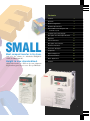
E500 SERIES
EXPANSIVE FUNCTIONALITY IN
A C OMPACT PACKAGE
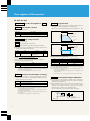
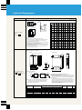
POWERFUL
Get a high torque (150%) at speeds as low as 1Hz
A regenerative braking resistor can be
connected (0.4K or more)
The high response current limit function helps provide safety
Now with an even higher output current rating
Mitsubishi’s New E500 Series
Offers Three Great Values.
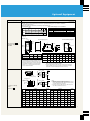
SIMPLE
Easy to operate.
The control panel now has a frequency setting knob as
standard equipment.
Easy to maintain.
Easy access make the cooling fan easy to replace.
Wiring is simple.
Screwed terminal plates are used for the main circuit and
for the control circuit (leads plug in).
ND CER
IT A
TI
UD
NT • JAPA
N
ME
A
ON
1
FOR EN
VIR
ION
AT
ORGA
TION
NIZ
CA
FI
NATIONAL
ACCREDITATION
OF CERTIFICATION
BODIES
Contents
Features
3
Networks
6
Model Configurations
7
Standard Specifications
8
External Dimension Diagrams and
Terminal Layouts
10
Terminal Connection Diagram
12
Description of Terminal Specifications
13
Operation
14
List of Parameters
15
Description of Parameters
18
Protective Functions
29
Connection Examples
30
Peripherals
32
Optional Equipment
34
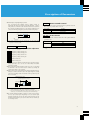
Only 85% the volume of a Mitsubishi FREQROLU100 (for FR-E520-0.2K).
Characteristic Data
39
Motor Applications
40
Height is now standardized.
Cautions
41
SMALL
Most compact inverter in its class.
All models from 0.1 to 3.7kW are the same 128mm in
height making panel layout easier. (Except FR-E540)
2
Features
Advanced Mitsubishi Technology Creates a Winner
Highly Cost-Effective and Very Powerful
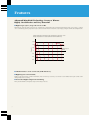
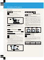
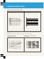
■ High Torque (150 %) at Speeds as Low as 1Hz.
Mitsubishi has achieved a 1Hz 150% torque by combining slip compensation with its original general-purpose flux vector control. Operation
can be controlled by general-purpose flux vector control even when motor characteristics vary simply by using the off-line auto-tuning function.
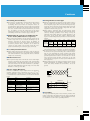
Sample speed-torque characteristics when general-purpose flux vector control
and slip compensation are selected (with an SF-JR 4P 0.75kW motor)
300
Torque (%)
200
100
Rotation speed
(r/min)
0
30 90180 300
600
900
1200
1500
1800
–100
–200
–300
■ A Brake Resistor can be Connected (0.4K and above).
■ High Response Current Limit.
Thanks to the high-response current limit function, there are fewer trips caused by overcurrent. It even handles instant peak currents when
starting during reverse coasting.
■ Now with a Higher Output Current Rating.
More powerful thanks to the highest output current rating in its class.
3
Features
Very Simple
Very Compact
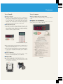
■ Easy to Operate
■ Most Compact Inverter in its Class
● We added a frequency setting knob (run by a varistor) to the
Only 85% the volume of a Mitsubishi FREQROL-U100 (for FR-E5200.2K).
control panel as standard. Variable speed operation is available
soon after power is turned on. The control panel is removable,
so you can install it on a main control panel with optional
equipment and “off-the-shelf ” cables. The knob itself is
removable. You can also operate it remotely using parameter
settings and externally input frequency setting signals.
■ Height is Now Standardized
All models from 0.1 to 3.7kW are the same 128mm in height. This
makes panel layout easier. (Except FR-E540)
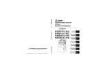
■ The Parameter Unit
● The FR-PU04 is another option available. It takes direct input
from a key pad. It uses a long-life backlit LCD and allows you to
copy parameters. Eight languages are available ( Japanese,
English, German, French, Spanish, Italian, Swedish, and Finnish).
Connect it with the separately sold cable.
FR-PU04 parameter unit (option)
● We've made parameter user group functions as standard. You can
select just the parameters you need for writing and reading to
simplify parameter management.
● You can use the setup software for parameter settings. We've
provided optional software that lets you use a personal computer
to assist you in everything from starting up the inverter to
maintenance.
■ Easy to Maintain
● Easy access makes changing the cooling fan very simple. Operating
life can also be increased by turning ON-OFF control on.
■ Easy to Wire
● A screwed terminal plate is used for the main circuit.
● A screwed terminal plate is also used for the all new control
Actual Size
circuit (with plug in leads). The wide lead holes allow two leads
to be plugged in simultaneously.
4
Features
Highly Cost-Effective Inverters
Environmentally Friendly
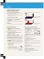
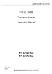
■ Newly Developed Soft-PWM Control
Motor noise data example (SF-JR 4P 3.7kW motor, carrier frequency 2kHz)
With Soft-PWM
Mitsubishi’s Soft-PWM switching system keeps noise to a minimum
(as low as a Mitsubishi FR-Z Series inverter).
Noise level
Note: The default setting is Soft-PWM control.
Sample Motor Noise Data (With an SF-JR 4P 3.7kW Motor and a 2kHz Carrier
Frequency).
■ Low Noise Operation Available
A higher carrier frequency can be used to reduce operating noise.
4
2
0
2k
4k
6k
8k
10k
Time (sec)
12k 0
Since the frequency components are
dispersed, the motor generates little
metallic noise and does not sound
unpleasant.
Frequency (Hz)
■ Can Handle Power Supply Harmonic
Restrictions
Without Soft-PWM
Noise level
A compact, lightweight DC reactor (FR-BEL) can be connected to all
capacities.
■ EMC Filter
Use the optional EMC filter to help to comply with EMC standards.
4
2
0
2k
4k
6k
8k
10k
12k 0
Since the frequency components are
concentrated, the motor generates a
grating metallic noise.
Frequency (Hz)
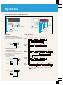
Full Product Line-Up
Full of Convenient Functions
■ Globally Compatible with Worldwide
Standards
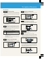
■ New Models Provide Compatibility with Many
New Applications
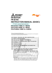
Example of PID control
● Compatible with UL, CSA, and EN standards (eligible for CE
● Stop selection: Select either
mark). (Models available soon.)
Fan
Inverter
■ Compatibility with 240V and 480V Power
Supply Now Standard
decelerating stop or coasting
stop, depending on machine
specification
● PID control: Facilitates flow
control using pumps.
■ Full Line-Up of Capacities Available
■ Ample Protection Functions for Safer Operation
The FR-E500 is the first line-up in its class to include 5.5kW and
7.5kW capacities, which extends the range to 0.1–7.5kW.
● Instantaneous power failure stop restart function: Can start while
● Select either IP20 or IP40 construction.
2
Setting
Detected value
(4 to 20mA)
Compatible with single phase 100V and 200V as well as three-phase
200V and 400V power supplies. (Output is three-phase 200V.)
■ Compatible with Numerous I/Os
so you can control operations via data communications once the
control panel is removed.
Note: An “off-the-shelf” converter is needed for RS-232C communication.
Model: Converter FA-T-RS40 Series
Mitsubishi Electric Engineering
Industrial Systems Division
Model:
Cable with built-in interface DAFX-CAB Series
Connector conversion cable DINV-485CAB
● The inverter can be run using PLC X and Y
instructions via CC-Link (compatible models
to be released soon), making programming
easy.
Temperature
sensor
coasting.
■ Compatible with Single-Phase Power Supplies
● We've added RS-485 communications functionality as standard,
IM
4
● Built-in electronic overcurrent protection
● Alarm retry selection
■ Compatibility with Data Communications Also
Standard
● Multi-speed operation (15 speeds)
● 4 to 20mA input
● Multi-input terminals: Select four inputs from 11 possible input
types
● Multi-output terminals: Select three outputs from 12 possible
output types
● 24V external power supply output (permissible values: 24V DC
0.1A)
■ Operating Functions
● JOG operation
● Frequency jumps (three points): Avoid the machine’s resonant
frequency
■ Other Convenient Functions
● Fast acceleration/deceleration mode
● Full monitoring: Monitors actual operating time and more
● Second functions: Switch between two sets of motor
characteristics
5
Time (sec)
● Zero current detection
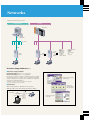
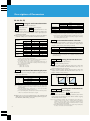
Networks
Compatible with RS-485 and CC-Link.
Computer Link
CC-Link
Master station
Setup software
Up to 32 units
RS-485
Inverter
FR-E500
Inverter
FR-E500KN
Inverter
FR-E540K
+
Option
FR-E5NC
Remote I/O
Remote device
Display
Local stations
Mitsubishi FA
equipment:
• AC servos
• Motion controllers
Compatible Products:
• Sensors
• Solenoids
• Meters
• Thermometers
• ID
• Bar codes
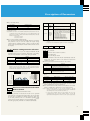
Inverter Setup Software (Note)
■ Inverter Setup Software
FR-SW0-SETUP-WJ (Windows* 3.1 or 95) ( Japanese)
FR-SW0-SETUP-WE (Windows* 3.1 or 95) (English)
Inverter setup software provides an amenable inverter operating
environment. Use it as a support tool for everything from inverter
startup to maintenance. It allows you to efficiently set parameters
and motor operation in Windows*.
Sample screen showing simple
parameter setting
*"Windows" is a registered trademark of Microsoft Corporation.
Note: Some models will soon be compatible.
■ Functions
Sample screen
showing monitoring
and meter displays
● Set and edit parameters ● Monitor ● Test operation
● Diagnosis ● System settings ● Files ● Windows ● Help
Power supply
RS-485
Converter
RS-232C
Sample screen showing
test operation
6
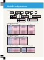
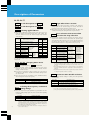
Model Configurations
■ Model
FR _ E520
Model
E510
E520
E540
Voltage class
100V class
200V class
400V class
Model
None
S
_ 3.7 K
Model
Inverter
0.1–
7.5
Shows the capacity
[kW]
Voltage class
Three-phase input
Single-phase input
Single-phase input
(double voltage output)
W
_
Model
None
C
Model
None
N*
Protective construction
IP20
IP40
Operating specifications
Frequency setting knob model
CC-Link
Note: * FR-E540 is compatible when equipped with
the optional FR-E5NC.
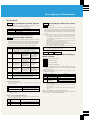
■ Three-Phase 200V Power Supply
Inverter
capacity (kW)
IP20
Model
IP40
Frequency setting knob model
CC-Link
Frequency setting knob model
0.1
FR-E520-0.1K
FR-E520-0.1KN
FR-E520-0.1K-C
0.2
FR-E520-0.2K
FR-E520-0.2KN
FR-E520-0.2K-C
0.4
FR-E520-0.4K
FR-E520-0.4KN
FR-E520-0.4K-C
0.75
FR-E520-0.75K
FR-E520-0.75KN
FR-E520-0.75K-C
1.5
FR-E520-1.5K
FR-E520-1.5KN
FR-E520-1.5K-C
2.2
FR-E520-2.2K
FR-E520-2.2KN
FR-E520-2.2K-C
3.7
FR-E520-3.7K
FR-E520-3.7KN
FR-E520-3.7K-C
5.5
FR-E520-5.5K
FR-E520-5.5KN
FR-E520-5.5K-C
7.5
FR-E520-7.5K
FR-E520-7.5KN
FR-E520-7.5K-C
■ Three-Phase 400V Power Supply
Inverter
capacity (kW)
Model
IP20
Frequency setting knob model
0.4
FR-E540-0.4K
FR-E540-0.4K-C
0.75
FR-E540-0.75K
FR-E540-0.75K-C
1.5
FR-E540-1.5K
FR-E540-1.5K-C
2.2
FR-E540-2.2K
FR-E540-2.2K-C
3.7
FR-E540-3.7K
FR-E540-3.7K-C
5.5
FR-E540-5.5K
FR-E540-5.5K-C
7.5
FR-E540-7.5K
FR-E540-7.5K-C
■ Single-Phase 200V Power Supply
Inverter
capacity (kW)
7
IP40
Model
IP20
Frequency setting knob model
■ Single-Phase 100V Power Supply
Inverter
capacity (kW)
Model
IP20
Frequency setting knob model
0.1
FR-E520S-0.1K
0.1
FR-E510W-0.1K
0.2
FR-E520S-0.2K
0.2
FR-E510W-0.2K
0.4
FR-E520S-0.4K
0.4
FR-E510W-0.4K
0.75
FR-E520S-0.75K
0.75
FR-E510W-0.75K
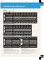
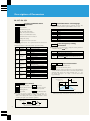
Standard Specifications
Ratings
■ Three-Phase 200V Power Supply
Model FR-E520-
0.2K
0.4K
0.75K
1.5K
2.2K
3.7K
5.5K
0.1
0.2
0.4
0.75
1.5
2.2
3.7
5.5
7.5
0.3
0.6
1.2
2.0
3.2
4.4
7.0
9.5
13.1
0.8 (0.8)
1.5 (1.4)
3 (2.5)
5 (4.1)
8 (7)
11 (10)
17.5 (16.5)
24 (23)
33 (31)
9
12
17
4.4 (9.7)
4.9 (10.8)
Power rated capacity (kVA) (Note 2)
Rated current (A) (Note 6)
Output
Overload current rating (Note 3)
150% for 60 seconds, 200% for 0.5 seconds (reverse limited characteristics)
Voltage (Note 4)
3-phase 200–240V, 50/60Hz
Power supply rated input:
AC (DC) voltage and frequency
Power
supply
7.5K
0.1K
(N)
Applied motor capacity (kW) (Note 1)
3-phase 200–240V, 50/60Hz (280V DC (Note 7) )
170–264V, 50/60Hz (252–310V DC (Note 7) )
Permissible AC (DC) voltage fluctuation
±5%
Permissible frequency fluctuation
Supply capacity (kVA) (Note 5)
0.4
0.8
1.5
2.5
4.5
Protective construction (JEM1030)
5.5
IP20
Cooling system
Forced air
Self-cooled
Approximate weight kg (lb)
0.6 (1.3)
0.6 (1.3)
0.8 (1.8)
1.0 (2.2)
1.7 (3.7)
1.7 (3.7)
2.2 (4.9)
0.4K
0.75K
1.5K
2.2K
3.7K
5.5K
7.5K
0.4
0.75
1.5
2.2
3.7
5.5
7.5
1.2
2.0
3.0
4.6
7.2
9.1
13.0
2.6 (2.2)
4.0 (3.8)
6.0 (5.4)
9.5 (8.7)
12
17
■ Three-Phase 400V Power Supply
Model FR-E540Applied motor capacity (kW) (Note 1)
Power rated capacity (kVA) (Note 2)
Rated current (A) (Note 6)
Output
Power
supply
1.6 (1.4)
Overload current rating (Note 3)
150% for 60 seconds, 200% for 0.5 seconds (reverse limited characteristics)
Voltage (Note 4)
3-phase 380–480V, 50/60Hz
Power supply rated input:
AC (DC) voltage and frequency
3-phase 380–480V, 50/60Hz
Permissible AC (DC) voltage fluctuation
325–528V, 50/60Hz
±5%
Permissible frequency fluctuation
Supply capacity (kVA) (Note 5)
1.5
2.5
4.5
Protective construction (JEM1030)
Cooling system
Self-cooled
Approximate weight kg (lb)
Applied motor capacity (kW) (Note 1)
Power rated capacity (kVA) (Note 2)
Output
1.9 (4.2)
2.0 (4.4)
0.2K
0.4K
0.75K
0.1
0.2
0.4
0.75
0.3
0.6
1.2
2.0
0.8 (0.8)
1.5 (1.4)
3 (2.5)
5 (4.1)
Overload current rating (Note 3)
150% for 60 seconds, 200% for 0.5 seconds
2.1 (4.6)
3.8 (8.4)
3.8 (8.4)
180–264V, 50/60Hz
Less than ±5%
0.5
0.9
Protective construction (JEM1030)
1.5
Self-cooled
0.6 (1.3)
0.6 (1.3)
1.0 (2.2)
0.2K
0.4K
0.75K
0.1
0.2
0.4
0.75
Power rated capacity (kVA) (Note 2)
0.3
0.6
1.2
2
Rated current (A) (Note 6)
0.8
1.5
3
5
Overload current rating (Note 3)
150% for 60 seconds, 200% for 0.5 seconds
Voltage (Note 4)
Power supply rated input:
AC (DC) voltage and frequency
Power
supply
3-phase 200–230V, 50/60Hz
Single-phase 100–115V, 50/60Hz
Permissible AC voltage fluctuation
90–132V, 50/60Hz
Less than ±5%
Permissible frequency fluctuation
2.5
Supply capacity (kVA) (Note 5)
0.5
0.9
Protective construction (JEM1030)
IP20
Cooling system
0.1K
Model FR-E510W-
Single-phase 200–240V, 50/60Hz
Permissible frequency fluctuation
Approximate weight kg (lb)
17
Applied motor capacity (kW) (Note 1)
3-phase 200–240V, 50/60Hz
Permissible AC voltage fluctuation
Supply capacity (kVA) (Note 5)
2.1 (4.6)
Output
Voltage (Note 4)
Power
supply
12
■ Single-Phase 100V Power Supply
0.1K
Rated current (A) (Note 6)
Power supply rated input:
AC (DC) voltage and frequency
9.5
Forced air
1.9 (4.2)
■ Single-Phase 200V Power Supply
Model FR-E520S-
5.5
IP20
Forced air
Cooling system
1.7 (3.7)
Approximate weight kg (lb)
Notes:
1. The applied motor shown is the maximum application capacity when a standard
four-pole Mitsubishi motors is used.
2. The rated output capacity is for a 230V output voltage.
3. After operation in the overload region, care should be taken to make sure that
standard operating conditions are once again met.
4. The maximum output voltage should not exceed the power supply voltage. Any
voltage less than that can be set as the maximum output voltage. The exception is
the FR-E510W series.
5. The power supply capacity will vary with the value of the power supply impedance
(including the input reactor and power lines).
6. The rated output current shown in parentheses is for low-noise operation with Pr. 72
1.5
2.5
IP20
Self-cooled
0.6 (1.3)
0.6 (1.3)
1.0 (2.2)
1.7 (3.7)
(PWM frequency selection) set to 2kHz or more when the ambient temperature is 40°C
(30°C for IP40 construction) or higher.
7. When using a DC power supply:
(1) Use DC 280V ±10% as a guide for the supply voltage fluctuation range and try
to keep voltage at 300V DC or less.
(2) There is a larger surge current when the power is turned on compared with an
AC power supply. Keep the number of “on-offs” to a minimum.
(3) Ensure a voltage of DC 300V to keep torque characteristics the same as with an
AC power supply.
8. Please refer to the sequencer side specifications below for information on the
communications specifications for CC-Link communication.
8
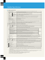
Standard Specifications
■ Common Specifications
Control method selection
Soft-PWM control or high carrier frequency PWM control; select V/F control or general-purpose flux vector control.
Output frequency range
Frequency
control
resolution
0.2 to 400Hz (variable starting frequency 0 to 60Hz)
Analog input
Digital input
(Note 4)
Analog input
Frequency
precision
(Note 4)
(Note 4)
Digital input
Between terminals 2 and 5 1/500 of the maximum set frequency (for the 5V DC input), 1/1000 of maximum set frequency (for the 10V DC
input at 4 to 20mA DC), or 1/256 of maximum set frequency (using control panel knob).
When set digitally on control panel 0.01Hz (less than 100Hz) or 0.1Hz (100Hz and up).
±0.5% of maximum output frequency 25°C (53°F) ±10°C (±21.2°F).
Within 0.01% of set output frequency.
Voltage/frequency characteristics
Any base frequency setting possible between 0 and 400Hz; constant torque or variable torque pattern selection possible.
Starting torque
Minimum 150% at 1Hz or minimum 200% at 3Hz: General purpose flux vector control when set for slip compensation.
Torque boost
Manual torque boost can be set between 0–30%
Acceleration time setting
0.01 to 3,600 seconds
Deceleration time setting
0.01 to 3,600 seconds
Acceleration/deceleration pattern
Linear, S-curve A, or S-curve B modes.
Regenerative (Note 1)
0.1 and 0.2K: 150% minimum; 0.4 and 0.75K: 100% minimum; 1.5K: 50% minimum; 2.2K, 3.7K, 5.5K and 7.5K: 20% minimum.
DC braking
Variable operation frequency (0 to 120Hz), operation time (0 to 10 seconds), operation voltage (0 to 30%).
Operation specifications
Braking torque
Current stall prevention operation level
Operation level is fixed, enable/disable selection.
High-response current restriction level
Operation level is fixed, enable/disable selection.
Frequency
setting
signal (Note 5)
Analog input
Starting signal
Alarm reset
(Note 5)
Individual selection of forward or reverse run; starting signal self-hold input (3-wire input) selective.
(Note 6)
Input signals
Used to reset alarm output provided when protective function is activated.
(Note 6)
Up to 15 set speeds (each speed can be set between 0 and 400Hz; speed can be changed via control panel or during operation).
(Note 6)
Selects 2nd function (acceleration time, deceleration time, torque boost, base frequency, electronic overcurrent protection).
(Note 6)
Instant shut-off of inverter output (frequency and voltage).
Current input selection
(Note 4)
Select input of frequency setting signal 4 to 20mA DC (terminal No.4).
Select self-hold at start
(Note 4)
Select self-hold of start signal.
External thermal input
(Note 6)
Switching between operation modes
Output signals
Display
PU and external operation Enables external switching between PU operation and external operation.
Enables external switching between V/F control and general-purpose flux vector control.
Maximum and minimum frequency settings, frequency jump operation, external thermal input selection, instantaneous power failure
restart operation, forward run/reverse run prevention, slip compensation, operation mode selection, off-line auto tuning function, PID
control (Note 4), and computer link operation (RS-485), CC-Link operation (Note 8).
Operation functions
Operation status
For meter (Note 4)
Displayed on
control panel
Select using
Pr.180 to Pr.183.
Thermal contact input for when stopping inverter with an externally mounted thermal relay.
(Note 4)
Switch between V/F and general-purpose
flux vector control (Note 6)
Operation status
Error details
Displayed on LED
Two types of open collector output can be selected from: inverter running, frequency reached, frequency detection, overload warning,
zero current detection, output current detection, maximum PID(Note 4), minimum PID(Note 4), PID forward run, PID reverse run(Note 4),
operation ready, minor failure, and error. One type can be selected for the contact output (AC 230V 0.3A, DC 30V 0.3A).
One type can be selected from: output frequency, motor current, or output voltage. Pulse train output (1440 pulse/second full scale).
Output voltage, output current, set frequency, and running.
Details of errors are displayed when the protective function activates. Details of up to four errors are saved.
Power on (POWER), Error (ALARM)
Protective and warning functions
Environment
0 to 5V DC, 0 to 10V DC, 4 to 20mA DC, built-in analog knob.
Input from control panel. (CC-Link Series: Input using CC-Link communications or parameter unit.)
2nd function selection
Output stop
(Note 4)
Digital input
Multi-speed selection
9
Operation current level setting possible (0 to 200% variable), enable/disable selection.
Voltage stall prevention operation level
(CC-Link Series: Power (POWER), Error (ALARM), Operational state (L.RUN, SD, RD, L.ERR))
Overcurrent shut-off (during acceleration, deceleration, and constant speed), regenerative overvoltage shut-off, undervoltage (Note 3),
instantaneous power failure (Note 3), overload shut-off (electronic thermal relay), output short, stall prevention, brake resistor overheating,
fin overheating, fan breakdown (Note 5), parameter error, PU disconnected, ground fault protection.
Ambient temperature
-10°C (-21.2°F) to +50°C (+106°F) (no freezing; -10 to +40°C for IP40 model).
Ambient humidity
90% RH or less (no condensation)
Storage temperature
(Note 2)
-20˚C (+42.4°F) to +65˚C (+137.8°F)
Atmosphere
Indoors (no corrosive gases, flammable gases, oil mist or dust)
Altitude and vibration
Maximum 1000m (3280.8 ft) above sea level, maximum 5.9 m/s2 {0.6G} (Conform to JIS C 0911.)
Notes: 1. The indicated control torque size is the short-term average torque (which changes with motor loss) when decelerated at maximum rate from 60Hz when the motor
is operated alone. It is not continuous regenerative torque. Deceleration from frequencies in excess of the base frequency will have lower average deceleration
torque values. The inverters have no built-in brake resistors, so when the regenerative energy is high, use the optional brake resistor. A BU model brake unit may
also be used (except with 0.1K and 0.2K models). The control torque when a brake resistor is used is shown on page 41; the same for when a brake unit is used
is shown on page 36.
2. Temperature to which units can be exposed for a short time, such as during transportation.
3. When an insufficient voltage or instantaneous power failure occurs, error display and output do not work, but the inverter is protected. Depending on the operating
status (e.g., the size of the load),. Overcurrent protection, regenerative overvoltage protection etc. may engage upon restoration of power.
4. This function is not available for the CC-Link Series.
5. For the CC-Link series, can be set by means of CC-Link communications or the optional parameter unit.
6. For the CC-Link series, can be set by means of CC-Link communications or one of the input terminals.
7. For the CC-Link series, display is possible when the optional parameter unit is in use.
8. This form is not available with the frequency setting volume type.
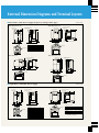
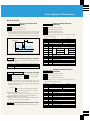
External Dimension Diagrams and Terminal Layouts
■ Three-Phase, 200V Power Supply (Frequency Setting Volume Type)
● FR-E520-1.5K, 2.2K
The frequency setting knob
can be removed.
2-ø5 (0.20) hole
The frequency setting knob
can be removed.
D1
118 (4.65)
128 (5.04)
D1
5
(0.20)
5
(0.20)
118 (4.65)
129 (5.08)
ø5 (0.20) hole
5
(0.20)
5
(0.20)
● FR-E520-0.1K–0.75K
Unit: mm (inch)
5 (0.20)
56 (2.20)
68 (2.68)
11 (0.43)
6
(0.24)
5 (0.20)
68 (2.68)
96 (3.78)
108 (4.25)
D2
11 (0.43)
6 (0.24)
Capacity
0.1K
0.2K
0.4K
0.75K
D
76 (2.99)
76 (2.99)
108 (4.25)
128 (5.04)
10
10
42
62
D1
(0.39)
(0.39)
(1.65)
(2.44)
D
Wiring holes
Cooling fan
Note: The 0.75K unit has a cooling fan.
● FR-E520-5.5K, 7.5K
2-ø6 (0.24) hole
The frequency setting knob
can be removed.
72 (2.83)
5
(0.20)
19.5 (0.77)
6 (0.24)
5 (0.20)
11 (0.43)
7
(0.28)
8
(0.31)
5 (0.20)
82.5 (3.25)
68 (2.68)
158 (6.22)
170 (6.69)
The frequency setting knob
can be removed.
244 (9.61)
260 (10.24)
118 (4.65)
128 (5.04)
2-ø5 (0.20) hole
5
(0.20)
● FR-E520-3.7K
6 (0.24)
11 (0.43)
7
(0.28)
D
7
(0.28)
Wiring holes
29
(1.14)
8
(0.31)
6
(0.24)
6
(0.24)
4
(0.16)
138 (5.43)
6 (0.24)
8
(0.31)
96 (3.78)
68 (2.68)
164 (6.46)
180 (7.09)
16 (0.63)
t
11 (0.43)
112.5 (4.43)
170 (6.69)
10 (0.39)
57.5
(2.26)
Wiring holes
Wiring holes
Cooling fan
Cooling fan
■ Single-Phase, 100V/200V Power Supply
Unit: mm (inch)
D1
2-ø5 (0.20) hole
D1
5
(0.20)
5
(0.20)
6
(0.24)
5 (0.20)
56 (2.20)
68 (2.68)
The frequency setting knob
can be removed.
5
(0.20)
The frequency setting knob
can be removed.
118 (4.65)
129 (5.08)
ø5 (0.20) hole
● FR-E520S-0.75K, FR-E510W-0.75K
118 (4.65)
128 (5.04)
5
(0.20)
● FR-E520S-0.1K–0.4K, FR-E510W-0.1K– 0.4K
4
(0.16)
11 (0.43)
6
(0.24)
7
(0.28)
Wiring holes
6
(0.24)
29
(1.14)
5 (0.20)
68 (2.68)
96 (3.78)
108 (4.25)
D2
11 (0.43)
6 (0.24)
11 (0.43)
7
(0.28)
D
D
Single-Phase, 200V
Capacity
D
0.1K
76 (2.99)
0.2K
76 (2.99)
0.4K
138 (5.43)
D1
10 (0.39)
10 (0.39)
42 (1.65)
Single-Phase, 100V
Capacity
D
0.1K
76 (2.99)
0.2K
106 (4.17)
0.4K
138 (5.43)
D1
10 (0.39)
10 (0.39)
42 (1.65)
Wiring holes
Single-Phase, 200V
Capacity
D
D1
D2
0.75K
131 (5.16) 65 (2.56) 8 (0.31)
Single-Phase, 100V
Capacity
D
D1
D2
0.75K
155 (6.10) 59 (2.32) 5 (0.20)
Cooling fan
Note: Single-phase 100V specifications units
do not have cooling fans.
10
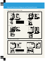
External Dimension Diagrams and Terminal Layouts
■ Three-Phase, 200V Power Supply (CC-Link)
● FR-E520-1.5KN, 2.2KN
ø5 (0.20) hole
5
(0.20)
5
(0.20
● FR-E520-0.1KN, 0.2KN, 0.4KN, 0.75KN
Unit: mm (inch)
6
(0.24)
5 (0.20)
56 (2.20)
66 (2.60)
6
(0.24)
128 (5.04)
118 (4.65)
5
(0.20)
128 (5.04)
5
(0.20)
118 (4.65)
2-ø5 (0.20) hole
8
(0.31)
5
30.6
(1.20)
55 (2.17)
D
D1
4
(0.16)
6
(0.24)
29
(1.14)
68 (2.68)
96 (3.78)
108 (4.25)
30.6 55 (2.17)
65 (2.56)
(1.20)
150.6 (5.93)
11 (0.43)
6
(0.24)
Wiring holes
Capacity
0.1KN
0.2KN
0.4KN
0.75KN
Wiring holes
D
95.6 (3.76)
95.6 (3.76)
127.6 (5.02)
147.6 (5.81)
D1
10 (0.39)
10 (0.39)
42 (1.65)
62 (2.44)
Note: The 0.75K unit has a cooling fan.
244 (9.61)
30.6 55 (2.17) 72 (2.83)
(1.20)
157.6 (6.20)
19.5
(0.77)
6
(0.24)
5
(0.20)
8 (0.31)
6
(0.24)
5 (0.20)
62.5 (2.46) 68 (2.68)
55 (2.17)
114.5 (4.51)
158 (6.22)
170 (6.70)
260 (10.24)
118 (4.65)
5
(0.20) 128 (5.04)
2-ø6 (0.24) hole
8
(0.31)
● FR-E520-5.5KN, 7.5KN
2-ø5 (0.20) hole
5
(0.20)
● FR-E520-3.7KN
6 (0.24)
Wiring holes
8 (0.31)
96 (3.78)
68 (2.68)
164 (6.46)
180 (7.09)
16 (0.63)
8 (0.31)
19.6
(0.77)
11 (0.43)
112.5 (4.43)
57.5
(2.26)
170 (6.69)
189.6 (7.46)
10 (0.39)
Wiring holes
■ Three-Phase, 400V Power Supply
Unit: mm (inch)
● FR-E540-0.4K, 0.75K, 1.5K–3.7K
● FR-E540-5.5K, 7.5K
.2
ø5
2-
0)
.2
150 (5.91)
138 (5.43)
150 (5.91)
138 (5.43)
2-
ø5
The frequency setting knob
can be removed
73 (2.87)
(0
208 (8.19)
The frequency setting knob
can be removed
D1
(0
128 (5.04)
0)
220 (8.66)
140 (5.51)
NP
128 (5.04)
5
(0.20)
7
(0.28)
Capacity
0.4/0.75K
1.5–3.7K
Cooling fan
11
D
D
116 (4.57)
136 (5.35)
5
(0.20)
238 (9.37)
D1
44 (1.73)
64 (2.52)
Note: FR-E540-0.4K, 0.75K do not have
cooling fans.
∗ With the CC-Link option, a signal terminal
mount protrudes about 14mm (0.55 inch)
from the surface.
Cooling fan
7
(0.28)
148 (5.83)
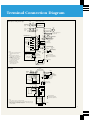
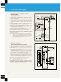
Terminal Connection Diagram
● Frequency Setting Volume Type
Inverter
FREQROL-E520S, E510W
NFB
MC
R (L2)
Single-phase
AC power
supply
S (L2) Inverter
FREQROL-E520, E540
NFB
MC
R (L1)
3-phase
AC power
supply
Motor
U
S (L2)
V
T (L3)
W
IM
Short bar
P1
PC
External transistor common
Control input signal
STR
N
(-)
High
speed
RH
A
Medium
speed
RM
Reverse run start
B
(Note 4)
Brake resistor
(optional)
Brake unit (optional)
High power factor
converter FR-HC
(option)
Error output
(Relay output)
C
RL
Low
speed
RUN
Output stop
Reset
MRS
FU
RES
SE
SD
FM
Notes:
1. This resistor is not needed when
calibrated with the control
panel.
2. When frequency settings are
changed often, we recommend
2W lkΩ.
3. Terminal SD and terminal PC
are common terminals. Please
do not interconnect them or
ground them together.
4. Single-phase 100V input
specifications units cannot
connect equipment.
R
PR
STF
Forward run start
Multi-speed
selection
(Maximum
15 speeds)
(+) P
DC supply-coordinating
reactor (optional)
Operating status output
(Open collector output)
Frequency
meter
Scale calibration
Moving coil type,
resistor
(Note 1)
1mA full scale
POWER
Frequency setting signal
Frequency potentiometer
1/2W1kΩ
(Note 2)
SD
10 (+5V)
(3)
(2)
(1)
Auxiliary input (-)
4 to 20mA DC (+)
2
(
5
(Analog common)
0 to 5V DC
0 to 10V DC
)
Main circuit terminal
Control circuit input terminal
Control circuit output terminal
4 (4 to 20mA DC)
Grounding
PU connector
(RS-485)
Control panel
(with frequency setting knob)
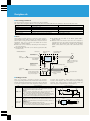
● CC-Link
Inverter
FREQROL-E520-KN
NFB
Motor
3-phase
AC power
supply
R (L1)
S (L2)
T (L3)
U
V
W
Output stop
MRS
P1
Reset
RES
(+) P
Ground
Short bar
Sink input
SD
Common
SD
PR
(Note 6)
Source input
P24
Reset
P24
(Note 5)
N
(–)
DC supply-coordinating
reactor (optional)
Brake resistor (optional)
Brake unit (optional)
High power factor
converter FR-HC
(option)
A
(Note 5)
B
C
Error output
(Relay output)
Terminating resistor
DA
(Note 7)
SW1
SW2
DA
DB
DB
DG
DG
SLD
SLD
SW3
SLD
SINK
FG
SOURCE
Main circuit terminal
Notes:
5. 0.1K, 0.2K do not have a braking transistor.
6. Terminal SD and terminal P24 are common terminals. Please do not
interconnect them or ground them together.
7. Please connect a terminating resistor across terminating inverter
terminals DA-DB.
POWER
ALARM
L. RUN
SD
RD
L. ERR
LED
LED
LED
LED
LED
LED
Control circuit input terminal
Control circuit output terminal
Grounding
PU connector
(RS-485)
12
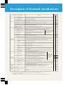
Description of Terminal Specifications
Model type
Terminal symbol
Main circuit
Connected to the commercial power supply. When using a DC power input for units with 3-phase power input
specifications, please connect it across terminals R (L1) and S (L2). When using a high power factor converter
(FR-HC), do not connect anything.
U, V, W
Inverter output
Connects the 3-phase squirrel cage motor.
P, PR
(+, PR)
Brake resistor connection
This terminal is used to connect the optional dedicated brake resistor (cannot be connected to the 0.1K and
0.2K models).
Brake unit connection
Connect the optional brake unit and high power factor converter to these terminals.
Power factor improvement
DC reactor connection Remove the short bar between terminals P (+) and P1 and connect the optional power
factor improvement DC reactor (FR-BEL).
Ground (Earth)
This is for grounding the inverter chassis. Always ground the inverter.
STF
Forward run start
Serves as the forward run command when terminals STF-SD are ON.
STR
Reverse run start
Serves as the reverse run command when terminals STR-SD are ON.
Multi-speed selection
The multi-speed type can be selected with a combination of shorts between
the terminals RH, RM and RL-SD.
MRS
Output stop
Inverter output stops when terminals MRS-SD are shorted (for 20ms or
more). This is used to cut off the inverter output when stopping the motor
with a magnetic brake.
RES
Reset
This is used to cancel the hold state when the protection circuit activates. Turn ON terminals RES-SD for
0.1 second or more, and then turn them OFF.
SD
Contact input common
This is the common terminal for the contact input terminal and the display meter (Note 4).
PC
External transistor common
When connecting a transistor output (open collector output) such as a programmable logic controller (PLC),
malfunctions caused by supplied current can be prevented by connecting the external power common for the
transistor output to this terminal. It is possible to use 24V DC 0.1A as the power supply.
–
10
Frequency setting power
supply
5V DC. Tolerable load current 10mA.
–
2
Frequency setting (voltage)
When 0 to 5V DC (or 0 to 10V) is input, the maximum output frequency is reached at 5V (10V). The input and
output are proportional. 5V DC and 10V DC are changed using Pr. 73 (See page 23). Input resistance is 10kΩ;
tolerable input voltage is 20V.
–
5
Frequency setting input
common
This is the common terminal for the frequency setting signal (Note 4).
Do not ground this common.
–
4
Frequency setting
(current signal)
Input 4 to 20mA DC. The maximum output frequency is reached at 20mA. At shipment, the inverter is adjusted
so that 4mA gives 0Hz and 20mA gives 60Hz. The maximum tolerable current is 30mA; the input resistance
is approximately 250Ω.
–
P24
Contact input
common (source)
Common terminal for contact inputs when using source input. When using source input, turn signals ON
by shorting to this terminal or OFF by leaving it open.
Alarm output
This is a contact output that indicates that the inverter's protection circuit has
functioned and the output has stopped. 200V AC 0.3A or 30V DC 0.3A. When an
alarm occurs, there is non-continuity between B-C (continuity between A-C); in normal
operations, there is continuity between B-C (non-continuity between A-C).
Inverter running
L level is output when the inverter output frequency is higher than the starting
frequency (the default of 0.5Hz is changeable); H level is output when stopped or
during DC braking (Note 1). Tolerable load: 24V DC 0.1A.
FU
Frequency detection
L level is output when the output frequency is higher than the set detection
frequency; H level is output when it is lower (Note 1). Tolerable load: 24V DC 0.1A.
–
SE
Open collector output
common
This is the common terminal for the terminals RUN and FU (Note 4).
–
FM
For display meter
When shipped, the inverter is set so that when terminals FM-SD are opened, 60Hz gives about 5V and output
frequency is proportional. The output voltage is a pulse waveform, so a digital display meter can be connected.
Pulse specification: 1440 pulse/sec. at 60Hz.
–
PU connector
RS-485 communications can be carried out using the PU connector.
• Complied standard: EIA Standard RS-485.
• Transmission format: multidrop link method.
• Communication rate: maximum 19200 baud. • Total length: 500 m (1640.4 ft).
RH, RM, RL
A, B, C
RUN
Communications
–
CC-Link
communications
DA
DB
DG
SLD
FG
CC-Link communication
signal
If terminals STF and STR-SD are
ON simultaneously, they serve as
the stop command.
–
–
The terminal function changes
according to the input terminal
function selection (Pr.180 to
Pr.183). (See page 26.)
–
The terminal function
changes according to
the selection for output
terminal function
(Pr.190 to Pr.192)
(See page 26.)
CC-Link communication signal Connects the master station and other local stations when using CC-Link
communications.
Notes: 1. The L level is when the open connector output transistor turns ON (continuity state). The H level is when it is OFF (non-continuity state).
2. In the case of units with single-phase power input specifications, the only AC power input terminals are R and S.
3.
: Applicable. – : Not applicable.
4. For the E540 models, terminals SD, 5 and SE are isolated. For other models, e.g. E510 terminal SE is isolated from terminals SD and 5.
13
CC-Link
Main circuit R, S, T
(L1, L2, L3) AC power
supply input
P, P1
(+, P1)
Control circuit
(output signals)
Frequency
setting
volume type
R, S, T
(L1, L2,
L3) (Note 2)
P, N (+, -)
Control circuit
(input signals)
Explanation
Terminal name
–
–
Operation
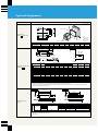
■ Control Panel (Frequency Setting Volume Type)
With Cover Open
Up/Down keys
STOP/RESET key
Frequency setting knob
Used while running
Reverse key
Hinged cover (removable)
STOP/RESET key
RUN key
Forward key
• 4-digit LED for monitor
• Run mode indicator
• Operating status
Setting key
Monitor area
MODE key
■ Key Operations
■ Operation
1. Using the Control Panel Knob
Use the RUN key to start and the STOP/RESET key to
stop. Set the operating frequency with the frequency
setting knob.
(Power On display)
● Frequency monitor
● Monitor
Display
SET
● Current monitor
Hz
MON
EXT
● Alarm monitor
SET
A
MON
EXT
SET
MON
EXT
SET
SET
(Note)
(Example of connection and setting)
SET
Inverter
Power supply
T (L3)
MODE
V
Control
panel
MODE
Motor
U
R (L1)
S (L2)
IM
W
● Write frequency
setting to memory
● Change frequency setting
● Frequency
Setting
Display
SET
Hz
Hz
PU
PU
Hz
MON
EXT
Use
to change
frequency setting
Pr.79=0 or 1
MODE
2. External Operation or Control
Panel/External Operation
Use Pr.79 to set the unit for external operation by
means of start signals and frequency instructions to
the control terminals or for operation via the control
panel or optional parameter unit (FR-PU04) with
external operation signals.
(Connection and setting example 1)
External operation
Inverter
Motor
Power supply
Frequency
potentiometer
R (L1)
U
S (L2)
V
T (L3)
W
STF
STR
SD
10
2
5
● Change parameter number
● Parameter
Setting
Display
PU
SET
PU
PU
Use
to change
parameter number
● Write value setting to
memory
● Change value setting
SET
Use
Press for
approximately
1.5 seconds
PU
to change value setting
SET
MODE
MODE
● External
operation
● Operation
Mode
Display
● PU operation
PU
● JOG operation
EXT
PU
IM
MODE
Alarm history
Pr.79=2
● Help
Display
MODE
Alarm history
clear
Parameter
clear
All clear
Read software
version
PU
(Connection and setting example 2)
Control panel knob and external start signals
Note: If SET is pressed continuously for approximately 1.5 seconds, the current display switches
to the initial power ON display.
Inverter
Motor
R (L1)
Power supply
S (L2)
IM
T (L3)
STF
STR
SD
Pr.79=3
14
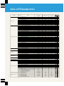
List of Parameters
Series name
Function
Pr. No.
0
Basic functions
Standard operation functions
Output terminal functions
2nd functions
Display functions
Restart
Supplementary functions
Operation selection functions
General-purpose flux vector
control
15
1
2
3
4
5
6
7
8
9
10
11
12
13
14
15
16
18
19
20
21
22
23
24
25
26
27
29
30
31
32
33
34
35
36
37
38
39
41
42
43
44
45
46
47
48
52
54
55
56
57
58
59
60
65
66
67
68
69
70
71
72
73
74
75
77
78
79
80
82
83
84
90
96
Name
Torque boost
(Note 1)
Setting range
0 to 30%
Maximum frequency
0 to 120Hz
Minimum frequency
0 to 120Hz
Base frequency (Note 1)
0 to 400Hz
Multi-speed setting (high speed)
0 to 400Hz
Multi-speed setting (middle speed)
0 to 400Hz
Multi-speed setting (low speed)
0 to 400Hz
Acceleration time
0 to 3600 s / 0 to 360 s
Deceleration time
0 to 3600 s / 0 to 360 s
Electronic thermal O/L relay
0 to 500A
DC injection brake operation frequency
0 to 120Hz
DC injection brake operation time
0 to 10 s
DC injection brake voltage
0 to 30%
Starting frequency
0 to 60Hz
Load pattern selection (Note 1)
0 to 3
JOG frequency
0 to 400Hz
JOG acceleration/deceleration time
0 to 3600 s / 0 to 360 s
High speed maximum frequency
120 to 400Hz
Base frequency voltage (Note 1)
0 to 1000V, 8888, 9999
Acceleration/deceleration reference frequency
1 to 400Hz
Acceleration/deceleration time increments
0, 1
Stall prevention operation level
0 to 200%
Stall prevention operation at double speed (Note 3)
0 to 200%, 9999
Multi-speed setting (speed 4)
0 to 400Hz, 9999
Multi-speed setting (speed 5)
0 to 400Hz, 9999
Multi-speed setting (speed 6)
0 to 400Hz, 9999
Multi-speed setting (speed 7)
0 to 400Hz, 9999
Acceleration/deceleration pattern selection
0, 1, 2
Regenerative function selection
0, 1
Frequency jump 1A
0 to 400Hz, 9999
Frequency jump 1B
0 to 400Hz, 9999
Frequency jump 2A
0 to 400Hz, 9999
Frequency jump 2B
0 to 400Hz, 9999
Frequency jump 3A
0 to 400Hz, 9999
Frequency jump 3B
0 to 400Hz, 9999
Speed display
0, 0.01 to 9998
Frequency at 5V (10V) input
1 to 400Hz
Frequency at 20mA input
1 to 400Hz
Up-to-frequency sensitivity
0 to 100%
Output frequency detection
0 to 400Hz
Output frequency detection for reverse rotation
0 to 400Hz, 9999
2nd acceleration/deceleration time
0 to 3600 s / 0 to 360 s
2nd deceleration time
0 to 3600 s / 0 to 360 s, 9999
2nd torque boost
0 to 30%, 9999
2nd V/F (base frequency)
0 to 400Hz, 9999
2nd electronic thermal O/L relay
0 to 500A, 9999
Control Panel / PU main display data
0, 23, 100
FM terminal function selection
0, 1, 2
Frequency monitoring reference
0 to 400Hz
Current monitoring reference
0 to 500A
Restart coasting time
0 to 5 s, 9999
Restart cushion time
0 to 60 s
Remote setting function selection
0, 1, 2
Shortest acceleration/deceleration time
0, 1, 2, 11, 12
Retry selection
0, 1, 2, 3
Stall prevention operation level reduction starting frequency (Note 3)
0 to 400Hz
Number of retries at alarm occurrence
0 to 10, 101 to 110
Retry waiting time
0.1 to 360 s
Retry count display erasure
0
Special regenerative brake duty
0 to 30%
Applied motor (Note 3)
0, 1, 5, 6, 15, 16, 23, 101 to 123
PWM frequency selection
0 to 15
0 to 5V, 0 to 10V selection
0, 1
Filter time constant
0 to 8
Reset selection/disconnected PU detection/PU stop selection
0 to 3, 14 to 17
Parameter write disable selection
0, 1, 2
Reverse rotation prevention selection
0, 1, 2
Operation mode selection (Note 3)
0 to 4, 6 to 8
Motor capacity
0.1 to 3.7kW, 9999
Motor excitation current
0 to 500A, 9999
Rated motor voltage
0 to 1000V
Rated motor frequency
0 to 400Hz
Motor constant (R1)
0 to 50Ω, 9999
0, 1
Auto-tuning setting/status (Note 3)
Minimum setting
0.1%
0.01Hz
0.01Hz
0.01Hz
0.01Hz
0.01Hz
0.01Hz
0.1 s / 0.01 s
0.1 s / 0.01 s
0.1A
0.01Hz
0.1 s
0.1%
0.01Hz
1
0.01Hz
0.1 s / 0.01 s
0.01Hz
0.1V
0.01Hz
1
0.1%
0.1%
0.01Hz
0.01Hz
0.01Hz
0.01Hz
1
1
0.01Hz
0.01Hz
0.01Hz
0.01Hz
0.01Hz
0.01Hz
0.001 r/min
0.01Hz
0.01Hz
0.1%
0.01Hz
0.01Hz
0.1 s / 0.01 s
0.1 s / 0.01 s
0.1%
0.01Hz
0.01A
1
1
0.01Hz
0.01A
0.1 s
0.1 s
1
1
1
0.01Hz
1
0.1 s
1
0.1%
1
1
1
1
1
1
1
1
0.01kW
0.01A
0.1V
0.01Hz
0.001Ω
1
Default setting
Frequency
setting
volume type
CC-Link
(Note 9)
6% / 4%
120Hz
0Hz
60Hz
60Hz
30Hz
10Hz
5s
5s
Rated output current
3Hz
0.5 s
6%
0.5Hz
0
5Hz
0.5 s
120Hz
9999
60Hz
0
150%
9999
9999
9999
9999
9999
0
0
9999
9999
9999
9999
9999
9999
0
60Hz (Note 4)
60Hz (Note 4)
10%
6Hz
9999
5 s / 10 s (Note 7)
9999
9999
9999
9999
0
0
60
Rated output current
9999
1.0 s
0
0
0
60Hz
0
1s
0
0%
0
1
0
1
14
0
0
0
9999
9999
200V / 400V
60Hz
9999
0
–
–
–
–
–
–
–
–
–
–
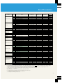
List of Parameters
Series name
Function
Communications functions
PID control
Indication
Supplementary function
Current detection
Auxiliary function
Supplementary function
Manufacturers
parameter
Initial monitor
User functions
Terminal function selection
Multi-speed operations
Auxiliary functions
Standard operation function
Auxiliary function
Stop selection functions
Calibration functions
Function selection
Pr. No.
Name
117
118
119
Station number
Communication speed
Stop bit length/data length
120
121
122
123
124
128
129
130
131
132
133
134
145
146
150
151
152
153
156
160
168
169
171
173
174
175
176
180
181
182
183
190
191
192
232
233
234
235
236
237
238
239
240
244
245
246
247
249
Parity check presence/absence
Number of communication retries
Communication check time interval
Waiting time setting
CR / LF presence/absence selection
PID action selection
PID proportional band
PID integral time
Upper limit
Lower limit
PID action set point for PU operation
PID differential time
Display language (When using FR-PU04)
Select frequency setting instruction
Output current detection level
Output current detection period
Zero current detection level
Zero current detection period
Stall prevention operation selection
User group read selection
Actual operation hour meter clear
User group 1 registration
User group 1 deletion
User group 2 registration
User group 2 deletion
RL terminal function selection (RY4)
RM terminal function selection (RY3)
RH terminal function selection (RY2)
MRS terminal (RY1) function selection
RUN terminal function selection (RX2)
FU terminal function selection (RX6)
A, B, C terminal (RY7) function selection
Multi-speed setting (speed 8)
Multi-speed setting (speed 9)
Multi-speed setting (speed 10)
Multi-speed setting (speed 11)
Multi-speed setting (speed 12)
Multi-speed setting (speed 13)
Multi-speed setting (speed 14)
Multi-speed setting (speed 15)
Soft-PWM setting
Cooling fan operation selection
Rated motor slip
Slip compensation response time
Constant-output region slip compensation selection
Ground fault detection at start-up (Y/N) (Note 8)
250
900
902
903
904
905
922
923
990
991
Stop selection
FM terminal calibration
Frequency setting voltage bias
Frequency setting voltage gain
Frequency setting current bias
Frequency setting current gain
Built-in knob bias
Built-in knob gain
Buzzer sound control (When using FR-PU04)
LCD contrast (When using FR-PU04)
Parameter set by manufacturer. Do not set.
Setting range
Minimum setting
Default setting
0 to 31
48, 96, 192
1
1
0
48
0, 1 (data length 8), 10, 11 (data length 7)
0,1, 2
0 to 10, 9999
0 to 999.8 s, 9999
0 to 15, 9999
0, 1, 2
0, 1, 9999
0.1 to 1000%, 9999
0.1 to 3600 s, 9999
0 to 100%, 9999
0 to 100%, 9999
0 to 100%
0.01 to 10.00 s, 9999
0 to 7
0, 1, 9999
0 to 200%, 9999
0 to 10 s
0 to 200.0%
0.05 to 1 s
0 to 31, 100
0, 1, 10, 11
–
–
0
0 to 999
0 to 999, 9999
0 to 999
0 to 999, 9999
0 to 8, 16, 18
0 to 8, 16, 18
0 to 8, 16, 18
0 to 8, 16, 18
0 to 99
0 to 99
0 to 99
0 to 400Hz, 9999
0 to 400Hz, 9999
0 to 400Hz, 9999
0 to 400Hz, 9999
0 to 400Hz, 9999
0 to 400Hz, 9999
0 to 400Hz, 9999
0 to 400Hz, 9999
0, 1
0, 1
0 to 50%, 9999
0.01 to 10 s
0, 9999
1
1
1
0.1 s
2
1
1
0.1 s
0.1 s
1%
1%
1%
0.01 s
1
1
0.1%
0.1 s
0.1%
0.01 s
1
1
–
–
–
1
1
1
1
1
1
1
1
1
1
1
0.01Hz
0.01Hz
0.01Hz
0.01Hz
0.01Hz
0.01Hz
0.01Hz
0.01Hz
1
1
0.01%
0.01 s
–
1
2
1
0
9999
1
0
100%
1s
9999
9999
0%
9999
23
0
150%
0
5.0%
0. 5 s
0
0
–
–
0
0
0
0
0
0
1
2
6
0
4
99
9999
9999
9999
9999
9999
9999
9999
9999
1
0
9999
0.05 s
9999
0, 1
0 to 100 s, 1000 to 1100 s, 8888, 9999
–
0 to 10V
0 to 60Hz
0 to 10V
1 to 400Hz
0 to 20mA
0 to 60Hz
0 to 20mA
1 to 400Hz
0 to 5V
0 to 60Hz
0 to 5V
0 to 400Hz
0, 1
0 to 63
1
1
–
0.01Hz
0.01Hz
0.01Hz
0.01Hz
0.01Hz
0.01Hz
1
1
0
9999
–
0V
5V
4mA
20mA
0V
5V
Frequency
setting
volume type
CC-Link
–
–
–
–
–
–
–
–
0Hz
60Hz
0Hz
60Hz
0Hz
60Hz
–
–
–
–
–
–
–
1
53
Notes: 1.
2.
3.
4.
5.
6.
7.
8.
This indicates a parameter whose setting is ignored when general-purpose flux vector control mode is selected.
The set values for the parameters in the shaded areas can be altered during operations even if Pr.77 (
Parameter write disable) is set to 0 (default setting).
Even if Pr.77 (Parameter write disable) is set to 2, the set value cannot be changed during operations.
Since they are calibrated before shipment, settings will vary slightly from inverter to inverter. Some are set to a frequency is slightly higher than 60Hz.
Some of the names of CC-Link Series functions differ from those of frequency setting volume type functions.
: Applicable. – : Not applicable.
The setting depends on the inverter capacity: (0.1K to 3.7K) / (5.5K to 7.5K)
The ground fault detection setting parameter is not applicable to the FR-E540 series.
The FR-E540 series is automatically set to detect ground faults.
9. The setting for the FR-E540-5.5K / 7.5K is 4%.
16
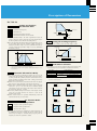
Description of Parameters
Pr. 0–Pr. 6
Note: “Parameter” is sometimes abbreviated “Pr.”
Pr. 0 Setting Torque Boost
● The motor torque can be adjusted at low frequencies to match
the load.
Pr. 4 – 6 Pr. 24 –27 Pr. 232 –239
Setting Multi-Speeds
Pr. 4
Three-speed setting (high speed)
Pr. 5
Three-speed setting (middle speed)
Pr. 6
Three-speed setting (low speed)
Output voltage
100%
Pr. 24 Multi-speed setting (speed 4)
Pr. 25 Multi-speed setting (speed 5)
Pr. 0
Setting range
Output frequency (Hz) Base frequency
Notes: 1. When general-purpose flux vector control mode is selected using Pr. 80,
this setting is ignored.
2. When using a motor that is dedicated for inverters (a constant torque
motor), change the settings as follows.
0.1–0.75K: 6%; 1.5–3.7K: 2%
If Pr.71 is changed to the settings for using constant torque motors, but
the default settings are not changed, the Pr.0 setting will switch to the
above values.
3. Default setting
FR-E540.....4% Others.....6%
Pr. 26 Multi-speed setting (speed 6)
Pr. 27 Multi-speed setting (speed 7)
Pr. 232 Multi-speed setting (speed 8)
Pr. 233 Multi-speed setting (speed 9)
Pr. 234 Multi-speed setting (speed 10)
Pr. 235 Multi-speed setting (speed 11)
Pr. 236 Multi-speed setting (speed 12)
Pr. 237 Multi-speed setting (speed 13)
Pr. 1
Pr. 2
Maximum frequency
Minimum frequency
Pr. 2
● The output frequency can be clamped by maximum and minimum
frequencies.
Output frequency
100%
Maximum
frequency
Minimum
frequency
Frequency setting
signal
Pr. 1
Pr. 2
Pr. 3
Pr. 239 Multi-speed setting (speed 15)
● Speeds can be selected by simply switching the external contact
signals (RH, RM, RL, and REX signals).
● All speeds (frequencies) can be set in the range 0-400 Hz while
the inverter is running. Change the settings by using the
keys while a multi-speed parameter is displayed. (Press the write
key to record the frequency setting in memory once you have
released the
keys.)
● Up to 17 speeds can be set by combining the maximum frequency
(Pr.1) and minimum frequency (Pr.2).
5V
(10V)
(20mA)
Speed 1
(High)
Note: Set Pr.18 if you need an maximum frequency of 120Hz or higher.
Pr. 3
Pr. 238 Multi-speed setting (speed 14)
Pr.19 Setting the Base Frequency
Base frequency
Output frequency
Pr.1
Setting Maximum and
Minimum Frequencies
RH
RM
Pr. 19 Base frequency voltage
Speed 2
(Middle)
Speed
Speed 3 4
(Low)
ON
Speed
5 Speed
6
ON ON ON
ON
ON
ON
RL
ON ON
ON
ON
REX
● Any base frequency (the reference frequency at the motor's rated
torque) can be set in the range of 0–400Hz to match the motor
rating.
● Motors rated at below the inverter's power supply voltage are best
used by setting Pr.19 (base frequency voltage). This is convenient
when using, for example, a 200V rated motor with a 230V power
supply.
Speed
9
Speed
8
Speed
10 Speed
11 Speed
12 Speed
13 Speed
14 Speed
15
ON ON ON ON
RH
Setting range for base frequency
RL
100%
Output voltage
REX
ON
ON
ON ON
ON
ON
ON ON ON ON ON ON ON ON
Pr. 19
Base frequency
voltage (Note 1)
Pr. 3 Base frequency
400Hz
Note: When Pr.19 is set to 8888, the maximum output voltage is 95% of the power
supply voltage. When Pr.19 is set to 9999 (the default setting), the maximum
output voltage is the same as the power supply voltage.
17
ON ON
RM
Notes: 1. When Pr.24–Pr.27 and Pr.232–Pr.239 are set to 9999 (default setting),
4 –7 and 8 –15 cannot be selected (or run).
2. Multi-speed settings have priority over analog input commands
(between terminals 2 and 5 or 4 and 5).
3. Multi-speed settings can be done during PU operation or external operation.
4. For three-speed settings (when Pr.24–Pr.27 and Pr.232–Pr.239 are not set),
selection of two or more speeds simultaneously will set the speed to the
speed set at the low speed signal terminal.
5. Terminals used for REX signal input are assigned by Pr.180 –Pr.183
(input terminal function selection).
Description of Parameters
Pr. 7–Pr.14
Pr. 8
Setting Acceleration/
Deceleration Time
Pr. 7
Acceleration time frequency
Pr. 8
Deceleration time
Output frequency
Pr. 7
Pr. 10 Operating frequency
Time
Pr. 12
DC brake
voltage
Pr. 20 Acceleration/deceleration reference
Operating
voltage
Time
Pr. 21 Acceleration/deceleration time increments
Pr. 11 Operating time
● Pr. 7 (acceleration time) is the time required from reach the
reference frequency of Pr.20 from 0Hz; Pr.8 (deceleration time) is
the time required to reach 0Hz from the setting of Pr.20.
● Pr. 21 (acceleration/deceleration time increments) allows you to
set the setting range and the minimum setting increment. A
setting of 0 provides a range 0–3600sec. (minimum increment of
0.1sec.); a setting of 1 provides a range of 0 –360 sec. (minimum
increment 0.01sec.).
Pr. 13 Setting the Starting Frequency
● The frequency at startup can be set in the range 0 – 60Hz.
Output frequency
(Hz)
Set range
60
Pr. 20
Operating frequency
Pr. 13
Acceleration
0
Frequency setting signal (V)
Forward
Pr. 7
Deceleration
Pr. 8
Time
ON
Time
Pr. 14 Load Pattern Selection
● The setting for motor overheating protection can be set as the
●
●
●
●
current value (A). Normally, the rated motor current for 50Hz is
set. This provides the optimum protection characteristics for low
speed operations, including when motor cooling power drops
during low-speed operation.
When 0A is set, the motor protection function does not engage.
(The inverter’s output transistor protection function does.)
When using a Mitsubishi fixed torque motor, set Pr.71 (applied
motor) to 1, 13, 15, or 16, select the 100 % continuous torque
characteristics at low speed, and set the motor’s rated current in
Pr. 9 (electronic thermal O/L relay).
The factory default setting is the inverter’s rated output current,
except for 0.1–0.75K inverters, for which it is 85% of the
inverter’s rated current.
When several motors are operated simultaneously, install an
external thermal relay on each motor.
Pr. 14 setting
Fixed torque load
1
Low-speed torque load
2
Pr.12 DC injection brake voltage
● The stopping precision for positioning or similar operations can
be adjusted to the load by setting the time for which the DC
brake torque (voltage) is activated during stopping and the
frequency at which the operation is started.
0% boost during forward
Note: When general-purpose flux vector control mode is selected with Pr.80, this
parameter setting is ignored.
Setting 0 (default)
Setting 1
Fixed torque load
(conveyors, dolleys, etc.)
Low-speed torque load
(fans and pumps)
100%
100%
Base frequency
Base frequency
Output frequency (Hz)
Output frequency (Hz)
Setting 2
Setting 3
For elevated loads
Boost during forward:
Parameter 0 setting
Boot during reverse: 0%
For elevated loads
Boot during forward: 0%
Boost during reverse:
Parameter 0 setting
100%
Output voltage
Pr. 11 DC injection brake operation time
0% boost during reverse
For fixed
torque elevation
3
DC Injection Brake
Pr.10 Pr.11 Pr.12
Adjustment
Pr. 10 DC injection brake operation frequency
Output characteristics
0
Output voltage
Electronic Thermal O/L Relay
characteristics) for your application and load characteristics.
100%
Forward
Reverse
Pr.0
Output voltage
Pr.9
● This allows you to select the optimum output characteristics (V/F
Output voltage
Notes: 1. For S-curve acceleration /deceleration pattern A (see Pr.29), the time is
that required to reach the base frequency (Pr. 3).
2. The frequency output to the frequency setting signal (analog) is set by
Pr. 38 or Pr. 39.
Reverse
Forward
Pr.0
Base frequency
Output frequency (Hz)
Base frequency
Output frequency (Hz)
18
Description of Parameters
Pr.15 – Pr. 30
Pr.15 Pr. 16 JOG Operation Settings
Pr. 24 Pr. 25 Pr. 26 Pr. 27
See the description of Pr. 4
Pr. 15 JOG frequency
Pr. 16 JOG acceleration/deceleration time
Pr. 29
● JOG operation can be run from the control panel.
(See manual for details.)
● JOG operation is not available during external operation.
Output frequency (Hz)
Pr. 20
Pr. 15
JOG frequency
setting range
Forward
Time
Reverse
Pr. 16
Forward
ON
Time
Reverse
Pr.18
ON
Time
Setting the High-Speed Maximum
Frequency
● Set this when operating beyond 120Hz.
● Set this parameter to have Pr.1 (maximum frequency) automatically
You can select the best pattern for your application.
● Setting 0 (linear acceleration/deceleration): The most common
acceleration/deceleration pattern. Normally, you should use this
setting.
● Setting 1 (S-curve acceleration/deceleration A): Use this pattern
when you need acceleration/deceleration in a short time frame in
high-speed zones of 60Hz and above. In this acceleration/
deceleration pattern, fb (the base frequency) is the inf lection
point. You can set the acceleration/deceleration time to match
the reduction in motor torque in fixed output operation zones of
60 Hz and above. It is suited for applications such as main axes of
machine tools.
● Setting 2 (S-curve acceleration/deceleration B): Because it
always accelerates/decelerates in an S-curve between f2 (current
frequency) and f1 (target frequency), the shock of acceleration/
deceleration is softened, which prevents load wobble.
Setting 0
changed to this value.
Setting 1
Pr.20 Pr.21 See the description of
Pr. 7
Pr.22 Pr.23 Pr.66
Setting the Stall Prevention Operation Level
Setting 2
S-curve acceleration/
deceleration A
Output frequency (Hz)
Linear acceleration/
deceleration
Pr.19 See the description of Pr. 3
tb
f2
t
t
Time
Pr.30 Pr.70
Pr. 70 Special regenerative brake duty
set to 150% (default).
increase, so acceleration is not always available. To improve the
motor operating characteristics, the stall prevention operation
level can be decreased in the high frequency zone. Normally,
Pr.66 is set to 60Hz and Pr.23 to 100%.
● When Pr.23 is set to 9999 (default), the stall prevention operation
level is the value set in Pr.22 and is constant to 400 Hz.
Stall prevention
operation level (%)
Pr. 23
Low reduction proportion
compensation coefficient (%)
Pr. 66
● Set this when you need a higher regenerative brake duty, for
instance, when operation involves frequent starts and stops.
Since the capacity of the brake resistor will have to be increased,
use the optional high-frequency brake resistor.
● Setting Method: After “Select Change Duty” is set to 1 in Pr.30,
use Pr.70 to set the duty.
Model
FR-E520-0.4K–3.7K /
55K / 72.5K
Default setting for
regenerative brake duty
(when Pr. 30=0)
3% / 2% fixed
Default setting for Pr.70
(when Pr. 30=0)
0%
(Note 1)
Notes: 1. Pr.70 is only displayed when Pr.30=1.
2. The brake duty is shown as the % ED of built-in brake transistor operation.
Pr. 23 = When 9999
Pr. 22
Time
Selecting Regenerative
Brake Duty
Pr. 23 Stall prevention operation at double speed
● When operated faster than 60Hz, the motor current does not
t
Time
Pr. 30 Regenerative function selection
● Use Pr.22 to set the stall prevention operation level. It is usually
S-curve acceleration/
deceleration B
f1
Pr. 22 Stall prevention operation level
Pr. 66 Stall prevention operation level reduction starting frequency
19
Acceleration/Deceleration Pattern
Selection
400Hz
Output frequency
Description of Parameters
Pr. 31–Pr. 43
Pr. 39 Frequency at 20mA Input
● To bypass the resonant frequency of a piece of machinery, jump
over that frequency. You can set three jump points. The jump
frequency can be the frequency either above or below the jump
point.
● The setting for 1A, 2A, or 3A becomes the jump point; operation
is at this frequency.
Jump (bypass operation) range
Output frequency (Hz)
Pr. 38
Pr. 35
Pr. 34
Pr. 33
Pr. 32
Pr. 31
3B
3A
frequency used for 20mA.
Pr. 39
fm 1
Output frequency
range
fm 2
Frequency setting signal
2B
2A
1B
1A
● The frequency setting signal from outside the inverter can set the
Output frequency (Hz)
Pr. 31– 36 Frequency Jumps
20mA
Note: There is no need to input a 20mA current between terminals 4 and 5.
*The operating frequency command
in the jump range is the operating
frequency given in the bulleted item.
Frequency setting signal
Notes: 1. No jumps are made when set to 9999 (the default).
2. During acceleration or deceleration, the operating frequency in the set
range is passed over.
Pr. 41 Up-to-Frequency Sensitivity
● The output signal operating width when the output frequency
reaches operating frequency can be adjusted within the range 0
to ±100%.
Adjustment range
Operating frequency
● The actual operating speed of machinery such as conveyors can
be displayed. You can set the control panel monitor to show
operating speed in the same units as the speed specifications of
the machinery you are using.
● Set the machine speed when operated at 60Hz.
Pr. 37 setting
Output frequency
Pr. 37 Setting the Speed Display Increment
Pr. 41
Time
Output signal
SU
H level
L level
L: Output transistor ON
H level
H: Output transistor OFF
Display
0.01– 9998
• The output frequency is displayed (default setting).
Pr. 42 Pr. 43 Output Frequency Detection
• Set the machine speed when operated at 60 Hz.
For example, if set for 950 (m/min.), 950 (without units) is
displayed when 60 Hz is output.
• The units of the operating speed are also converted in the display.
Pr. 42 Output frequency detection
Notes: 1. The set unit is only used with this parameter for the PU monitor display
and setting operating speed. Other parameters for speeds (such as Pr.1)
should be set as frequencies.
2. The speed display is converted from output frequency; it does not match
the actual RPM.
3. Due to the setting resolution, frequencies set directly through the control
panel may differ from operating speed.
Pr. 38 Frequency at 5V (10V ) Input
● You can set the frequency when the frequency setting signal
input externally is 5V DC (or 10V DC).
Pr. 43 Output frequency detection for reverse rotation
● When the output frequency rises above an arbitrary detection
frequency (set with output frequency detection Pr.42), the level
becomes L; below that frequency, it remains H. This can be used
for engaging electromagnetic brakes, for release signals, and so on.
Output frequency
0
Any detection frequency
can be set
Pr. 42
Time
Output signal
FU
H level
Output frequency (Hz)
L: Output transistor ON
Pr. 38
fm 1
Output frequency
range
fm 2
Frequency setting signal
5V (10V)
H level
L level
H: Output transistor OFF
● Use Pr.43 to engage frequency detection only when operating in
reverse. (The value set in Pr.42 only works for forward operation.)
This can be effective when timing use of electromagnetic brakes
based on forward (up) and reverse (down), as in elevators. The
default setting is 9999, which means that the value set in Pr.42 is
used for both forward and reverse.
Adjustment range
Note: There is no need to input a 5V DC (or 10V DC) voltage between terminals
2 and 5.
Forward
Detection
frequency
Output frequency
Pr. 42
Time
Pr. 43
Reverse
20
Description of Parameters
Pr. 44 –Pr. 65
Pr. 44 – 48 Setting the 2nd Control Functions
Pr. 52
0
Pr. 44 2nd acceleration/deceleration time
Output frequency
Pr. 45 2nd deceleration time
Pr. 47 2nd base frequency
Pr. 46 2nd torque boost
Pr. 48 2nd electronic thermal O/L relay
● You can change settings such as the acceleration/deceleration time
and boost all at once using external contact signals (between
terminals RT and SD).
● This is useful when switching between two motors with different
parameter settings, such as elevation and lateral movement.
Signal between terminals
RT and SD
Set Function
Acceleration time
Deceleration time
Torque boost
Base frequency
Electronic thermal
O / L relay
Parameter number
OFF
Pr.7
●
ON
●
Pr.8
●
Pr.45
●
Pr.0
●
Pr.46
●
Pr.3
●
Pr.47
●
Pr.9
●
Pr.48
Stopped
Running
Output frequency
Set frequency
Output frequency
Output current
Output current
Output voltage
Output voltage
Error display
Error display
Notes: 1. During an alarm, the frequency when the alarm occurred is displayed.
2. While output is stopped (MRS), everything is handled the same as when
the inverter is stopped. When off-line auto-tuning is engaged, monitoring
of the tuning status takes priority.
Pr. 54 FM Terminal Function Selection
● Use the FM output terminal by connecting a meter that displays
●
Pr.44
100
Running/stopped
Notes: 1. If Pr. 45 is set to 9999 (the default), the value set in Pr.44 is used for the
second acceleration and deceleration times.
2. When general-purpose flux vector control mode is selected using Pr.80,
the settings of Pr.0, Pr.3, Pr.46, and Pr.47 are ignored.
3. As with Pr.7 and Pr. 8, the second acceleration/deceleration times of
Pr. 44 and Pr. 45 are the times until the setting of Pr.20 (base frequency
for acceleration/deceleration).
4. Default setting of Pr.44
0.1K to 3.7K: 5 seconds
5.5K to 7.5K: 10 seconds
Pr. 52 Control Panel/PU Main Display Data
● You can choose from among five signals by setting the numbers
the operating status. You can select whether to display output
frequency or the motor current (output current).
Pr. 54 setting
Signal type
0
Output frequency (default setting)
1
Motor current (output current)
2
Output voltage
Note: The output frequency gain can be adjusted using Pr.55 (frequency monitor
reference); the motor current gain can be adjusted using Pr.56 (current
monitor reference).
Pr. 55 Pr. 56 Setting the Monitor Reference
Pr. 55 Frequency monitoring reference
Pr. 56 Current monitoring reference
● Pr. 55 is set with an output frequency that gives a pulse train
output between terminals FM and SD when Pr. 54 is set to 0
(output frequency) of 1440 pulse/sec.
● Pr. 56 is set with a motor current value that gives a pulse train
output between terminals FM and SD when Pr. 54 is set to 1
(motor current) of 1440 pulse/sec.
shown in the table below.
1440 pulse/sec.
23
Output frequency
Hz
Output current
A
Output voltage
V
Alarm display
–
Actual running time
hr
Output frequency
Pr. 55
Output current
Pr. 56
Notes: 1. When set to 0, you can select the item monitored, in order, from output
frequency through to alarm display using the setting key. (This is the
factory default.)
2. The actual running time is counted from 0 to 99990 hours and then
cleared, whereupon counting resumes from 0.
3. The actual running time is counted in terms of time the inverter operates.
Time is not counted when the inverter is stopped.
Note: The maximum pulse train output of the FM terminal is 2400 pulse/sec.
● When Pr.52 is set to 100, the output frequency value monitored will
● You can have the inverter start operating when the power comes
differ when it is stopped and when it is running. (While stopped, the
Hz LED blinks; while running, it stays lit.)
21
1440 pulse/sec.
Display units
Output or display
0, 100
Signal type
Output or display
Pr. 52 setting
Pr. 57 Pr. 58
Restarting After an Instantaneous
Power Failure
Pr. 57 Restart coasting time
Pr. 58 Restart cushion time
back on after an instantaneous power failure without stopping
the motor (the motor coasts).
Notes: 1. The operation of restarting after an instantaneous power failure uses a
system in which the motor starts by reducing voltage that gradually
cushions the output voltage at the set frequency regardless of the
motor’s coasting speed. This system does not detect the motor’s coasting
speed (the speed searching method).
2. When the instantaneous power failure stop period is long, restarting may
not always be smooth. See manual for details.
Description of Parameters
● Pr.57 (Coasting Time)
Pr. 57 setting
Restarting possible
9999 (default)
No
0 or 0.1– 5
(Note)
Pr.60 setting
Function set
Description of operation
Parameter
automatically
set
0 (default)
Normal
operating
mode
–
–
Yes
The coasting time is the time spent waiting for control to start, which is used for
restarting after recovery.
Note: When Pr. 57 is set to 0, the standard coasting time described below is set. You
can generally operate at this setting, but you can also adjust the time in the
range of 0.1–5 seconds to better suit the inertial moment (GD2) of the load
and the size of the torque.
0.1–1.5K: 0.5 seconds
2.2–7.5K: 1.0 second
1, 2, 11, 12
Shortest
acceleration/
deceleration
mode
● Pr.58 (Output Voltage Cushion Time)
You can run the inverter using the default setting of 1 second for
this parameter, but you can also adjust the output voltage
cushion time for restarting between 0 and 60 seconds to better
suit the load specifications (the inertial moment and the size of
the torque).
Pr. 59 Remote Setting Function Selection
● By setting Pr.59 to 1 or 2, you can change the RH, RM, and RL
terminal functions to the acceleration, deceleration, clear setting,
and same input functions of the remote setting box FR-FK.
“1” : Stall prevention operation level 150%
“2” : Stall prevention operation level 180%
“11”: Stall prevention operation level 150%
when brake resistor or brake unit is used
“12”: Stall prevention operation level 180%
when brake resistor or brake unit is used
Remotely set function
Frequency setting
memory function (Note 1)
0
×
–
1
●
●
2
●
×
Pr.7
(shortest),
Pr.8
(shortest)
Notes: 1. Set individual parameters when you need control suited to the application
as well.
2. Accelerates in the shortest time regardless of the Pr.7 and 8 settings.
Pr. 65 Pr. 67 Pr. 68 Pr. 69
Retry Selection
Pr. 65 Retry selection
Pr. 67 Number of retries at alarm occurrence
Pr. 68 Retry waiting time
● Retry is a function in which the inverter automatically resets the
alarm when an inverter alarm occurs and then restarts and
continues operation.
● Use Pr. 65 to select the alarms for which a retry is done.
Pr. 65 setting
Note: When the RH-SD terminals or RM-SD terminals stay open for at least one
minute or when the start signal changes to OFF, the operating frequency
setting is placed in memory. If the power is turned off thereafter, operation
resumes from this setting when power goes back on.
Retry type
0
Retry for all alarms except fin overheating (FIN),
PU disconnected (PUE), and CPU error (CPU).
1
Retry when an overcurrent cut-off (OCT) occurs.
2
Retry when a regenerative overvoltage cut-off (OVT) occurs.
3
Retry when a regenerative overvoltage cut-off (OVT) or
overcurrent cut-off (OCT) occurs.
Example of connections
Example of Operation
Note: The acceleration/deceleration time is the longer
of the Pr.44/45 settings or the Pr.7/8 settings.
Output frequency
(Note 2)
Pr. 69 Retry count display erasure
Operation
Pr. 59 setting
Set to accelerate/decelerate the motor in the shortest
time.
The inverter makes acceleration/deceleration in the shortest
time using its full capabilities. During deceleration, an
insufficient brake capability may cause the regenerative
overvoltage alarm (E.OV3).
Forward
STF
Reverse
STR
● You can also set the number of retries when an alarm occurs with
Pr. 67.
Acceleration
RH
Deceleration
RM
Pr. 67 setting
Number of retries
Clear setting
RL
0 (default)
No retries
–
1–10
1–10
Not output
01–110
1–10
Output
SD
Forward (STF)
Acceleration (RH)
Deceleration (RM)
Maximum length
of wiring is 30m
Clear setting (RL)
Alarm error signal output
● You can set the length of time to wait after an inverter alarm
before restarting (0.1–360 sec.) using Pr. 68.
● You can find out how many retires were needed to successfully
Pr. 60
Shortest Acceleration/Deceleration
Mode Selection
Pr. 60 Shortest acceleration/deceleration mode
● When this parameter is selected, the inverter can be operated
even when the acceleration/deceleration times are not set under
the same type of conditions as though appropriate values were
set for each parameter. This is a convenient operating mode
when you just need the settings to be approximately right.(Note 1)
That the appropriate parameters are selected automatically.
restart by reading Pr. 69. When set to 0, the count is erased.
Notes: 1. When using this function, be sure to take precautions so that the
operator or machinery is not injured when the inverter automatically
starts running after the retry wait time set with Pr.68.
2. A reset when restarting using the retry function does not clear
accumulated data, such as for the electronic thermal O/L relay and
regenerative brake duty (which is not the case for a power supply reset).
22
Description of Parameters
Pr. 66 –Pr.77
Pr. 74 Input Filter Time Constant
Pr.66 See the description of Pr. 22
● You can set the built-in input filter constant of the frequency
Pr.70 See the description of Pr. 30
setting signal for the external voltage or current. This aids in
removing noise from the frequency setting circuit.
● When noise prevents stable operation, increase the filter time
constant. Increasing the setting will lower responsiveness.
Pr. 71 Selecting Applied Motor
● When using a Mitsubishi constant torque motor, set Pr. 71 to 1 for
both V/F control and general-purpose flux vector control. The
electronic thermal is set to the constant torque motor thermal
characteristics.
Electronic thermal characteristics
0, 100
Thermal characteristics to match
general-purpose motors (default)
1, 101
Thermal characteristics for Mitsubishi constant
torque motor
2, 102
Standard motor
13, 113
Constant torque motor
23, 123
Mitsubishi standard
motor SF-JR4P
(1.5 kW max.)
5, 105
Standard motor
15, 115
Fixed torque motor
6, 106
Standard motor
16, 116
Constant torque motor
Standard
Constant
torque
●
●
●
Select “off-line
auto-tuning
setting”
Star
wiring
Delta
wiring
Direct input
of motor
constant
allowed
inverter error when the inverter detects that a PU (control panel
and parameter unit) connector has become disconnected from
the inverter. You can select either a reset terminal function or a
function that decelerates to a stop when PU stop key is hit.
Pr. 75 setting
Reset signal
0
Input always accepted
1
Input accepted only when
protective function engaged
●
2
Input always accepted
●
3
Input accepted only when
protective function engaged
●
●
●
●
Set 3, 13, 23, 103, 113, or 123 for off-line auto-tuning. When a number in the range 100– 123
is set, the electronic thermal switches to fixed torque thermal characteristics when the RT
signal goes ON.
Pr. 72 Pr. 240 Changing Motor Noise
Pr. 72 Select PWM frequency
Reset Selection/Disconnected PU
Detection /PU Stop Selection
● This function sounds an alarm and stops the inverter with an
Motor
Pr. 71 setting
Pr. 75
Pr. 240 Set Soft-PWM
● When the PWM carrier frequency is lowered, motor noise
increases, but the noise generated from the inverter and the
leakage current decrease.
● Pr.72 can be set between 0 and 15; however, for 0, the value is
0.7kHz, for 15 the value is 14.5kHz, and all other settings are the
set value in kHz.
● You can use Pr.240 to set whether to have Soft-PWM control,
which changes the motor noise quality.
14
(default)
Input always accepted
Input accepted only when
protective function engaged
15
16
Input always accepted
17
Input accepted only when
protective function engaged
PU disconnected
Keeps operating
even when PU
disconnected
Inverter output
cuts off when PU
disconnected
PU stop selection
Decelerates to
a stop only when
PU stop key is
entered in PU
operating mode
Keeps operating
even when PU
disconnected
Inverter output
cuts off when PU
disconnected
Stops when PU
stop key is
entered in all
operating modes
(PU, external,
communications,
etc.).
Notes: 1. When the RES signal goes ON during operation, the inverter cuts off
the output while the signal remains ON; the electronic overcurrent
protection and regenerative brake duty are reset, and the motor coasts
to a stop.
2. When something other than a PU is connected (such as when doing RS485 serial communications with a computer), no PU disconnections are
detected.
3. Input from the PU reset key is only accepted when protective functions
are engaged, regardless of the Pr.75 settings.
Pr. 77 Parameter Write Disable Selection
● This parameter disables writing in control panel and parameter
unit functions.
Pr. 240 setting
Description
0
Soft-PWM control disabled
1
Soft-PWM control enabled
Note: This is only valid when Pr.72 (Set PWM frequency) is 0 –5.
Selecting the Frequency Command
Voltage Range
Pr. 73
● You can switch the input (terminal 2) specifications for the
frequency setting voltage signal. Be sure to set this when inputting
0 to 10V DC.
23
Pr. 73 setting
Terminal 2 input voltage
0
DC 0 – 5V input (default)
1
DC 0 –10V input
Notes: 1. To change the maximum output frequency when inputting the maximum
frequency command voltage (current), set the frequency setting voltage
(current) gain with Pr.903 (or Pr. 905). Since the acceleration /deceleration
time is the slope to the acceleration /deceleration reference frequency, it
is not affected by changing the Pr.73 setting.
2. When operating the inverter while connected to a frequency meter, be
sure to set this value to 0.
Pr. 77 setting
Write disable function
0
Parameter write enabled.
(Only while stopped in PU mode. Default.)*1
1
Parameter write disabled.*2
2
Parameter write also enabled during operation.*3
Notes: 1. Monitor-related Pr. 54–56 can be set at any time.
2. Pr.77 and 79 (operating mode selection) are write-enabled.
3. Some parameters are write-disabled during operation. See the parameter list.
Description of Parameters
Pr. 78 –Pr. 96
Pr. 78 Reverse Rotation Prevention Selection
● Set this parameter to prevent problems caused by reverse
rotation caused by mistaken start signal input.
Pr. 78 setting
you need a large starting torque or sufficient low-speed torque.
Set the motor capacity. When using a constant torque motor,
set Pr.71 (applied motor selection) to 1 or 13–16 (constant torque
motor).
Forward or reverse both allowed. (Default.)
1
Reverse disabled.
2
Forward disabled.
Note: These settings are valid for both PU and external operation.
Pr. 79 Operation Mode Selection
● The inverters have two operating modes: operation by external
signal and operation by PU (control panel and parameter unit).
You can set this parameter to use either or both. The setting for
this parameter can be changed even when in external mode.
Operation by control panel and parameter unit is called “PU operation” in this table.
Setting
0
(default)
Pr. 80 Motor capacity
● General-purpose flux vector control can be advantageous when
Rotation direction
0
Pr. 80 General-Purpose Flux Vector Control
Description
You can change between PU operation mode and external operation
mode using the keys of the control panel and parameter unit. See the
columns for values 1 and 2 for the descriptions of the modes.
Notes: General-purpose flux vector control can be used with the following restrictions.
1. The motor is a standard, general-purpose squirrel-cage motor whose
capacity (0.1 kW or higher) is equal to or less than the inverter capacity.
In the fixed torque motor (SF-JRCA) 200V class 4P, it can be used with
0.4–3.7kW motors.
2. The motor has 2, 4, or 6 poles. (Fixed torque motors must have four
poles.) There is no need to set the number of poles.
3. The motor must be used alone (one inverter per motor).
4. The maximum wiring length between motor and inverter cannot exceed
30 m. Beyond 30 m, use off-line auto-tuning.
Usage under other conditions may not provide the best performance.,
Note: This control system is not the same as the Mitsubishi advanced flux vector
control used in the FR-A500 Series inverters.
Operating mode
Operating frequency
Start signal
1
PU operating mode
Set by control panel
knob or digitally by
control panel or
parameter unit key
Control panel start
(FWD and REV)
keys or parameter
unit FORWARD and
REVERSE keys
2
External mode
External signal input
(between terminals
2 (or 4) and 5, multispeed selection)
External signal input
(STF and STR
terminals)
Pr. 82 Motor excitation current
External and PU
operating mode
Set by control panel
knob or digitally by
control panel or
parameter unit key,
multi-speed selection
External signal input
(STF and STR
terminals)
Pr. 90 Motor constant (R1)
4
External and PU
operating mode
External signal input
(between terminals
2 (or 4) and 5, multispeed selection)
Control panel start
(FWD and REV)
keys or parameter
unit FORWARD and
REVERSE keys
6
Switchover mode
3
7
PU operation interlock
8
Switch operating mode external signal (can’t switch during operation)
• PU operation is selected when X16 signal is OFF
• External operation is selected when X16 signal is ON
Pr.82 Pr.83 Pr. 90, 96
Off-Line Auto-Tuning and Manual Setting of
Motor Constant
Pr. 83 Rated motor voltage
Pr. 96 Auto-tuning setting/status
● You can automatically measure the motor constant to be used
with general-purpose flux vector control with the auto-tuning
(off-line) function.
● After you select general-purpose flux vector control, set the
following parameters.
Pr. number
Note: Use Pr.180-183 (input terminal function selection) to assign the terminal that
the X16 signal will use.
● Pr.79 = 6: Switchover Mode
When set to switchover mode, you can change between PU and external
operation at any time.
Switchover mode
Switch
1
External operation to PU operation
External mode data is brought into PU mode
2
PU operation to external operation
When mode switches, the external knob value
and starting signal are used.
Note: In switchover mode, frequency cannot be set with the control panel knob
(which is disabled).
Name
Setting range
71
Applied motor
3, 13, or 23
83
Rated motor voltage
0 –1000V
84
Rated motor frequency
0 – 400 Hz
96
Off-line auto-tuning
setting /status
0
No off-line auto-tuning
1
Off-line auto-tuning without running the motor
Notes: 1. Motor shall be connected. When tuning starts, however, the motor
should be stopped.
2. You can do off-line auto-tuning even with a load (friction, constant load,
etc.) on the motor.
3. You cannot tune special motors such as high-slip motors and high-speed
motors.
● You can monitor the results of tuning with Pr. 90.
● You can set the motor excitation current and motor constant with
Pr. 82 and Pr. 90. (See manual for details.)
● Pr.79 = 7: PU Operation Interlock Function
When set to PU operation interlock, PU operation can be interlocked as shown
below by turning the MRS signal ON or OFF.
MRS
signal
External operation mode
PU operation mode
ON
Output stops
PU operation enabled, parameter setting enabled.
OFF
External operation
enabled.
Both PU operation and parameter setting disabled.
Forcibly switched to external operation mode.
24
Description of Parameters
Pr. 117–Pr. 151
Pr. 117–124
RS-485 Communications
Operation
Pr. 145 Switch Parameter Unit Language
● You can switch the language that the parameter unit uses. This
setting is enabled when the optional FR-PU04 unit is used.
Pr. 117 Station number
Pr. 118 Communication speed
Pr.145 setting
Pr. 119 Stop bit length/data length
Language
0
Japanese (default)
1
English
Pr. 120 Parity check presence/absence
2
German
Pr. 121 Number of communication retries
3
French
4
Spanish
Pr. 122 Communication check time interval
5
Italian
Pr. 123 Waiting time setting
6
Swedish
7
Finnish
Pr. 124 CR/LF presence/absence selection
● RS-485 communications can be performed from the inverter’s PU
connector.
Pr.146
For RS-485 communication, set the following parameters. (See manual for details.)
Pr. number
Name
117
Local station
118
Communication
speed
119
120
Stop bit length/
data length
No. of parity
checks
Setting
0-31
Description
Set inverter station number
Select Frequency Setting
Instruction
● Select whether to set the frequency using the control panel knob
or digitally using the
keys.
48
4800 baud
96
9600 baud
Pr.146 setting
192
19200 baud
0
Built-in frequency setting control volume
1
Digital frequency setting using the
0
1 stop bit, 8 data bits
1
2 stop bit, 8 data bits
10
1 stop bit, 7 data bits
11
2 stop bit, 7 data bits
0
No parity check
1
Odd parity
2
Even parity
0 –10
121
Number of
communication
retries
0
122
Communication
check time
interval
123
Waiting time
setting
124
CR/LF presence/
absence
selection
9999
0.1– 999.8
Set permitted No. of retries for
communications errors
Do not check for communications errors
Communication disabled
Set communication time interval (in seconds)
9999
Halt communication check
Set send wait time (in ms)
Set send wait time in communication
0
No CR or LF
1
Only CR
2
Both CR and LF
Pr. 150 Pr. 151 Current Detection
Pr. 150 Output current detection level
Pr. 151 Output current detection period
● When the output current exceeds the level set in Pr.150 (output
current detection level) and the time set in Pr.151 (output current
detection time) elapses, the output terminal goes ON. Once
the output signal goes ON, it stays ON for at least 100 ms
(approximately).
Note: These parameter settings are disabled during PU operation.
100ms
Pr. 128 –134 PID Control
Pr. 128 PID action selection
Pr. 132 Lower limit
Pr. 129 PID proportional band
Pr. 133 PID action set point
for PU operation
Pr. 131 Upper limit
OFF
Pr. 150
Pr. 151
Time
Quantities provided externally as voltage or digital values are
used as the settings; PID control is performed with 4–20mA
current input signals as the feedback quantities.
Setting
(voltage or digital value)
PID
operation
Inverter
drive
circuit
Measured value (4~20mA)
25
ON
Pr. 134 PID differential time
● Use these for process controls of flow, airflow, pressure, etc.
+
-
Output current
Output current detection
signal (Y12)
OFF
Pr. 130 PID integral time
keys
Frequency setting using the built-in frequency setting control
volume is available when the frequency setting has been set at
(OH2) using the
keys
* CC-Link type does not have this function.
0 –150
9999
9999
Select frequency setting
IM
Note: Use parameters 190–192 (output terminal function selection) to assign the
terminal that the output current detection signal (Y12) will use for output.
Description of Parameters
Pr. 152 –Pr. 192
Zero Current Detection
Signals
Pr. 152 Pr. 153
Pr. 180 –183
Input Terminal Function
Selection
Pr. 152 Zero current detection level
Pr. 180 RL terminal function selection
Pr. 153 Zero current detection period
Pr. 181 RM terminal function selection
● When the output current falls below the level set in Pr.152 (zero
current detection level) and the time set in Pr.153 (zero current
detection time) elapses, the output terminal goes ON. The output
signals stays ON for about 100ms even after conditions change.
Pr. 182 RH terminal function selection
Pr. 183 MRS terminal function selection
● Functions can be freely assigned to input terminals by setting
0 –18 for Pr.180–Pr.183.
Pr. number
100ms
Output current
Output current detection
signal (Y13)
OFF
ON
OFF
Pr. 153
Time
Note: Use Pr.190–192 (output terminal function selection) to assign the terminal
that the zero current detection signal (Y13) will use for output.
Pr. 156 Stall Prevention Operation Selection
● This selects how the stall prevention and high-response current
limit function work.
Pr.156 setting
Stall prevention and high-response current limit function operation
0
100
Terminal
RL terminal function selection
181
RM terminal function selection
RM
182
RH terminal function selection
RH
183
MRS terminal function selection
MRS
Setting
Pr. 152
Name
180
Terminal
RL
Terminal function
Remote setting
(clear settings)
0
RL
Low speed
1
RM
2
RH
High speed
3
RT
Second function selection
4
AU
Current input selection
5
STOP
Start self-hold selection
6
MRS
Stop output
7
OH
External thermal input
8
REX
15 speed setting (combination of 3 speeds, RL, RM, and RH)
16
X16
Switch between PU operation to external operation
18
X18
Switch between V/F to general-purpose flux vector control
Pr. 59 = 0
Middle speed
Pr. 59 = 1
Remote setting
(deceleration)
Remote setting
(acceleration)
Operates (default)
Does not work during regenerative operation.
Note: The functions of the STF, STR, and RES terminals cannot be changed.
Note: There are other settings than the above. See manual for details.
Pr. 190 –192
Pr.160 Pr. 173 –176 User Group Selection
Pr. 160 User group read selection
Pr. 175 User group 2 registration
Pr. 173 User group 1 registration
Pr. 176 User group 2 deletion
Pr. 174 User group 1 deletion
● Up to 32 of the parameters can be registered in two user groups.
The registered parameters can be read and written. When a user
group is selected with Pr.160 (user group selection), unregistered
parameters cannot be read.
Pr.160=0001
1 User group 1 (0: Disabled, 1: Enabled)
2 User group 2 (0: Disabled, 1: Enabled)
● Registering Parameters in a User Group:
Write the parameter number to be registered in Pr.173 (user
group 1 registration) or Pr.175 (user group 2 registration).
● Deleting Parameters from a User Group:
Write the parameter number to be deleted in Pr.174 (user group
1 deletion) or Pr.176 (user group 2 deletion).
Pr.171 Actual Operation Hour Meter Clear
● Write 0 to clear the actual operation time monitor (Pr.52=23).
Output Terminal Function
Selection
Pr. 190 RUN terminal function selection
Pr. 191 FU terminal function selection
Pr. 192 A, B, C terminal function selection
● Set Pr.190–Pr.192 to 0–99 or 9999 to freely assign functions to the
output terminals (including relays)
Pr. number
Name
190
RUN terminal function selection
191
FU terminal function selection
192
A, B, C terminal function selection
Setting
Terminal
0
RUN
Inverter running
1
SU
Reach frequency
Terminal
RUN
FU
A, B, C
Terminal function
3
OL
Overload warning
4
FU
Frequency detection
11
RY
Inverter ready to run
12
Y12
Output current detection
13
Y13
Zero current detection
14
FDN
PID minimum
15
FUP
PID maximum
16
RL
PID forward reverse output
98
LF
Minor breakdown output
99
ABC
Error output
26
Description of Parameters
Pr. 232 –Pr. 991
Pr. 232 –239 See the description of Pr. 4
Pr.250 Stop Selection
● This parameter selects the stopping method used when the start
signal goes OFF (decelerating stop or coasting stop).
Pr.244 Fan ON-OFF Control
When Pr.250 is 9999 (decelerating stop when start signal goes OFF):
● Controls the cooling fan.
Start signal
Fan operation
ON
0
No ON-OFF control (Factory setting)
1
ON-OFF control (Always ON during inverter operation; while the
inverter is stopped, goes ON-OFF according to temperature control.)
OFF
Decelerating stop
when start signal goes OFF
Output frequency
Pr. 244 setting
Pr. 245 –247 Slip Compensation
Decelerating time (Pr.8)
DC brake
time
Pr. 245 Rated motor slip
When Pr. 250 is 0–100 (coasting stop when start signal goes OFF):
Pr. 246 Slip compensation response time
Start signal
Pr. 247 Constant-output region slip compensation selection
ON
● The motor slip can be estimated from the inverter output current
Output frequency
Pr. 250
and the motor rotation held constant.
Pr. number
Name
Description
Default
245
Rated motor slip
Sets the rated slip of the motor
9999
246
Slip compensation response
time
Sets the response time for slip
compensation.(Note 1)
500 ms
Rated slip =
Base frequency synchronization speed – rated RPM
Base frequency synchronization speed
×100%
Pr. 247 selects whether or not to activate slip compensation in the rated output zone
(the frequency zone above the frequency set in Pr. 3).
Pr. 247 setting
Function
0
No slip compensation in constant output zone.
9999
Slip compensation in constant output zone.
Notes: 1. Decreasing this value increases the response time but also makes
regenerative overvoltage errors (OVT) more frequent, for example,
when there is greater load inertia.
2. There is no slip compensation when Pr.245 is set to 9999.
OFF
Output cuts off after set time
when start signal goes OFF
Motor coast to a stop
Time
When Pr. 250 is 8888, the terminal STF and STR functions switch as follows.
(STF: Start signal, STR: Rotation direction signal)
STF
STR
OFF
OFF
Inverter Operating Status
OFF
ON
Stop
ON
OFF
Forward
ON
ON
Reverse
Stop
When Pr. 250 is 1000–1100 seconds, the STF and STR terminal functions are the same as
when Pr. 250 is 8888. It will stop while the start signal is OFF by cutting off output (coasting
to a stop) after (Pr. 250 setting)–1000 seconds.
Notes: 1. When Pr. 250 is something other than 9999, the RUN signal goes OFF
when the start signal goes OFF.
2. When the restart signal goes ON while the motor is coasting, the motor
starts from 0Hz.
3. When Pr.250 is 0, the cut-off of output is the within the shortest time.
Pr.249 Check for Ground Faults at Startup
● You can choose whether to check for ground faults at startup.
Ground faults can only be implemented immediately after the
start signal is input to the inverter.
Pr. 249 setting
Description
0
Don’t detect ground faults (default)
1
Detect ground faults. Output is delayed about 20ms at every startup
when ground faults are checked.
Notes: 1. When parameter 249 is 1 and a ground fault is detected, error indicator
“E.GF” is displayed and output cuts off.
2. The protective function does not engage for ground faults that occur
while the inverter is running.
3. If the motor capacity is less than 100W, ground fault protection may not
be available.
4. This parameter is not applicable to the FR-E540 series.
Pr.900 FM Terminal Output Calibration
● You can use the control panel to calibrate meters connected to
the FM terminal. This calibration function is shared by all monitor
functions selected with Pr.54.
● The FM terminal output is pulse output like that shown in the
diagram below. You can set Pr. 900 so you can use the control
panel for scale calibration of meters connected to the inverter
without having to install a scale calibrating resistor.
(See the manual for more information about calibration.)
meter.
(1mA fullDisplay
scale analog meter. )
FM
T1
1mA
+
–
DC8V
T2
SD
27
Pulse width T1: Adjust with Pr.900
Pulse period T2: Set with Pr.55
(valid only with frequency monitor)
Description of Parameters
● Monitoring Using Digital Display Meter
You can display data digitally using a digital counter by
employing the pulse train output of the FM terminal. Output is
1440 pulse/sec. at the full scale value described in the section on
Pr. 54. When operating frequency is selected for monitoring, you
can set the FM output frequency for this terminal using Pr.55.
Pr.990 Buzzer Sound Control
● You can turn the buzzer sound used when parameter unit FR-
PU04 keys are pressed either on or off.
Pr. 990 setting
Description
0
No buzzer
1
Buzzer (default)
Digital display meter
FM
Pulses/sec.
+
–
Pr.991 LCD Contrast
SD
● You can adjust the contrast of the LCD on the optional FR-PU04
parameter unit.
Note: Set before shipment so that 1 mA provides full scale and a FM output
frequency of 1440 Hz at 60Hz.
Pr. 991 setting
Description
0 to 63
53 (default)
Bright
Dark
Pr. 902–905 Pr. 922–923
Frequency Setting Signal Gain and Bias Adjustment
Note: The LCD contrast setting will not be recorded unless you press the [WRITE ]
key.
Pr. 902 Frequency setting voltage bias
Pr. 903 Frequency setting voltage gain
Pr. 904 Frequency setting current bias
Pr. 905 Frequency setting current gain
Pr. 922 Built-in knob bias
Pr. 923 Built-in knob gain
● You can set any size (slope) of output frequency for the frequency
setting signal (0 to 5V, 0 to 10V, or 4 –20mA DC) and control
panel knob setting.
● Input between inverter terminals 2 and 5 (0 to 5V, 0 to 10V DC)
or terminals 4 and 5 (4–20 mA DC) or calibrate by turning the
control panel knob to any position.
● Set Pr. 902–Pr.905 to some setting other than the digital frequency
setting 0.00. Set Pr.922 and Pr.923 to the digital frequency setting
0.00 in PU operating mode and calibrate when operation by the
knob is selected.
Calibrating by applying a voltage
Example: Apply V1(V) between terminals 2 and 5 to
set the bias and apply V2(V) to set the gain.
Output frequency
(Hz)
Gain
Pr. 923
Pr. 904
Pr. 922
Pr. 903
Pr. 905
Pr. 902
0
V1
V2 5V (10V)
Frequency setting signal
Notes: 1. When Pr. 903 and Pr. 905 are set, the 5V input frequency (Pr.38) and
20 mA input frequency (Pr. 39) are automatically overwritten.
2. An error will result if the differences between Pr.902 and Pr. 903, Pr. 904
and Pr. 905, or Pr. 922 and Pr. 923 exceed 5% of the maximum input.
● To calibrate without inputting a voltage or current, set a frequency
in Pr. 38 (5V (10V ) input frequency) or Pr.39 (20 mA input
frequency). When Pr. 38 is set, the values of Pr.902 and Pr. 903 are
no longer valid; when Pr.39 is set, the values of Pr.904 and Pr. 905
are no longer valid.
28
Protective Functions
The following protective functions are provided for the protection of the inverter itself (except for the motor's electronic thermal relay), but they
may also function when the inverter breaks down.
Type (Note 5)
Function name
Description
When the inverter output current exceeds the rated current by more than approximately
200% during acceleration/deceleration or at constant speed, the protective circuit activates,
halting inverter output.
Over-current shut-off
Regenerative overvoltage
shut-off
If the DC voltage in the inverter's internal main circuit exceeds the rated value as a result
of regenerative energy generated through motor braking during acceleration/deceleration
or at constant speed, the protective circuit activates, halting inverter output. There are also
cases where it is activated by surge voltage generated in the power supply system.
Display
Major
fault
Accelerating
(OC1)
Constant speed
(OC2)
Decelerating
(OC3)
Accelerating
(OV1)
Constant speed
(OV2)
Decelerating
(OV3)
●
●
Motor
The electronic overcurrent protection inside the inverter detects motor overheating resulting from overloading
or a decline in cooling capacity at constant speed, activating the protective circuit and halting inverter output.
The electronic thermal relay cannot protect multipolar and other special motors, or several motors working
together, so a thermal relay should be installed on the inverter's output side.
(THM)
●
Inverter
In the case where a current flows that is at least 150% of the rated output current but does not exceed the
overcurrent shut-off (OC) level (200% max.), the electronic thermal relay activates according to reverse time
characteristics to protect the main circuit transistors, and halts inverter output. (150% of overload capacity,
60 seconds.)
(THT)
●
(FIN)
●
Overload shut-off
(electronic thermal
relay) (Note 1)
Fin overheat
If the cooling fin overheats, the fin overheat sensor activates and halts inverter output.
Fan breakdown
When the inverter has a built-in cooling fan, FN will be displayed on the control panel when the cooling fan
breaks down or an operation different from the setting of Pr.244 (cooling fan operation selection) is performed.
Inverter output does not stop.
(FN)
Output ground fault
overcurrent protection
When a ground fault occurs at the inverter output (the load side) when the inverter is started up and the
ground fault overcurrent flows, inverter output stops. Use Pr.249, “Ground fault detection at Startup (Y/N)”
to set whether to engage the protection function. (Note 8)
(GF)
●
External thermal relay
operation (Note 2)
When an externally installed motor overheating protective thermal relay or temperature relay within the motor,
etc., activates (relay contact open), the inverter can be stopped if the contact is input to the inverter. Even if
the relay contact resets automatically, the inverter will not restart unless it is reset also.
(OHT)
●
Brake transistor error
detected (Note 3)
When the optional brake resistor is connected and a brake transistor error occurs (for example, when the
energy regenerated from the motor becomes very large), this is judged a brake transistor error and inverter
output stops.
(BE)
●
Parameter error
Generated when an error occurs in a stored parameter (e.g. E2ROM breakdown).
(PE)
●
PU disconnected
Inverter output halts when communication between the main unit and the PU is interrupted by disconnection
of the PU, etc., when Pr. 75 is set to 2, 3, 16, 17.
(PUE)
●
(RET)
●
(LF)
●
(CPU)
●
Number of retries exceeded
When operations cannot be restarted normally within the set number of retries, inverter output is halted.
Output phase loss detection
Detects when the inverter looses an output phase (U, V or W).
CPU error
If the built-in CPU does not complete operations within the prescribed time, it self-diagnoses a fault and halts
inverter output.
Current limit/
Stall prevention
During
acceleration
When a current of 150% (Note 4) or more of the inverter's rated current flows in the motor, the rise in frequency
is stopped until the load current declines, preventing the inverter from executing an over-current shut-off. The
frequency is increased again once the current falls below 150% of the rated value.
and monitor
displayed
alternately.
At constant
speed
When a current of 150% (Note 4) or more of the inverter's rated current flows in the motor, the frequency is
lowered until the load current declines, preventing the inverter from executing an over-current shut-off. The
frequency is restored to the set level once the current falls below 150% of the rated value.
and monitor
displayed alternately.
During
deceleration
If the motor's regenerative energy is excessive and surpasses its braking capacity, the decline in frequency is
halted, preventing the inverter from executing an over-current shut-off. Once the regenerative energy has
declined, deceleration continues. When a current of 150% (Note 4) or more of the inverter's rated current flows
in the motor, the decline in frequency is halted until the load current declines, preventing the inverter from
executing an over-current shut-off. The frequency is lowered once again once the current falls below 150% of
the rated value.
(Note 7)
Checks for breaks in the CC-Link connection cable. This protection function also engages when reset with the
master unit in NET mode (Pr. 79 = 2). (Inverters are set to NET mode when shipped.)
Optional equipment error
(OLT)
Minor
fault
●
●
and monitor
displayed
alternately.
(OPT)
●
Notes: 1.
2.
3.
4.
5.
When the inverter is reset, the internal heat counting data in the electronic thermal O/L relay (overcurrent protection) is initialized.
External thermal relay operations are only performed when Pr. 180 –Pr. 183 (input terminal function selection) is set to OH.
This only functions when the optional brake resistor is connected.
Any stall prevention operation current can be set. Set to 150% when shipped.
Major Breakdowns: Inverter output is cut off by the protection function and an error signal is output.
Minor Breakdowns: The protection function does not cut off output. A minor breakdown signal can be output if the parameter is set to do so.
6. In the case of the CC-Link Series, the ALARM lamp lights up the when the protection function activates. If parameter unit FR-PU04 is in use, its displays switches
automatically to indicate an error.
7. CC-Link Series only.
8. Pr.249 is not applicable to the FR-E540 series.
The FR-E540 series is automatically set to detect ground faults.
29
● Alarm output signal held........When the magnetic contactor (MC) provided on the power supply side of the inverter is opened at the activation of the protective function,
the inverter's control power will be lost and the alarm output will not be held.
● Alarm display..........................When the protective function is activated, the control panel display automatically switches to the above indication.
● Resetting method....................When the protective function is activated, the inverter output is kept at a stop. Therefore, unless reset, the inverter cannot restart. Switch
power off once, then on again; or short reset terminal RES-SD for more than 0.1 second, then open. If RES-SD are kept shorted, "Err." appears
(flickers) to indicate that the inverter is being reset.
Connection Examples
■ Basic Wiring Diagram
(Operation by External Signal)
● This is the basic inverter wiring diagram when operating by using
Inverter
forward and reverse switches, an external potentiometer etc.
● For safety, install a magnetic contactor on the input side.
NFB
MC
R (L1)
Power supply
Notes: 1. To install the model MRS optional external brake resistor to increase
braking power, connect it between terminals PR and P (+).
2. Set Pr. 54 to be able to select an output current display rather than
frequency.
3. Since Pr. 900 can be used to calibrate the scale of the display meter,
there is no need for a scale calibration resistor except when remote
calibration is required.
E500
LED display
U
Motor
S (L2)
V
IM
T (L3)
W
(Note 1)
PR
Forward
STF
Reverse
STR
Reset
RES
(+)P
N
(–)
A
SD
B
10(5V)
C
Frequency meter
1/2W1kΩ
Error output
(operates during errors)
(Note 3)
(Note 3)
Scale calibration Multi-function display
meter output
resistor
(1mA full scale)
2
FM
5
SD
■ Basic Wiring Diagram
(Main Circuit Input Cut-Off by Alarm)
● This is the circuit when cutting off the main inverter circuit input
Inverter
Power supply
MC
with a magnetic contactor when an inverter alarm stop occurs.
R (L1)
● The terminal FM-SD output can be either a frequency or a motor
current signal. (See the description of Pr. 54 on page 21 for
details.)
● For reset input, you can also select a function (error reset) that
accepts signals only when the inverter alarm stops. (See the
description of Pr. 75 on page 23 for details.)
E500
LED display
U
Motor
S (L2)
V
IM
T (L3)
W
Resistor
unit
Brake unit FR-BU
P
200/100
Tr
F
CR
1
P1
Inverter alarm
(opens when alarm occurs)
(inverter trips)
B
N
HA
HB
HC
N
C
01X
HB HC
01Y
Preparing
for operation
Stop
01X 01Y
CR
2
MC
Forward start
STF (forward when closed)
Reverse start
STR (reverse when closed)
Reset
RES (Resets when closed)
MC
CR
1
MC
CR
2
Error reset
CR
2
Inverter error
SD
10 (5V)
R
Inverter error lamp
Frequency
meter
1/2W1kΩ
0–5 V/0–10V input
2 (input resistance 10kΩ)
5
30
Connection Examples
■ Automatic Operation Using DC 4 –20mA
Current Signals
MC1
(Note 1)
OCR (Note 3)
(Building Air-Conditioners)
● This is a sample circuit for automatic operation when used in
●
●
●
●
●
combination with controllers such as temperature control for
building air-conditioners.
You can switch from inverter operation to commercial power
supply operation and vice versa. To switch from commercial
power supply operation to inverter operation, first stop the
motor.
Operation automatically switches to commercial power supply
operation when an alarm stop occurs in the inverter.
Assign the AU signal to the RM terminal to be able to switch
between a 4 to 20mA signal from the controller and a manual
signal (voltage) from the speed setter.
Set Pr.75 to change the reset input signal to an error reset that is
only accepted when an inverter alarm stop occurs.
For safety, install a magnetic contactor on the input side.
Power supply
NFB
Automatic
commercial operation
MC2
R (L1) LED display
S (L2)
U
Motor
V
IM
T (L3)
W
F
Manual
CR
1
Stop
OCR MC2 MC
1
MC1
RT CR3
Inverter
operation
CR3
MC1
MC2
MC2
Reset
MC
2
CR
2
RT
CR
3
CR2
Related parameters: Pr. 75 (Reset selection) and Pr. 180 –Pr. 183 (Input
terminal function selection).
CR1
Notes: 1. Use mechanically interlocked magnetic contactors for MC1 and MC2.
2. Connect OCR to the commercial circuit side. If connected to the
inverter, it may be engaged unexpectedly by leakage current during
low noise operation. We recommend the electronic thermal O/L relay
function (Pr.9) for motor protection when the inverter is operating.
3. This terminal is used when Pr.181=4.
Inverter
MC
A
RES
SD
B
C
STF
RM (Note 3)
SD
10
Frequency
meter
1/2W1kΩ
0–5V/0–10V input
2 (input resistance 10kΩ)
5
Temperature Controller
sensor etc.
4–20mA signal
Current input
4 (input resistance 250Ω)
■ Multi-Speed Operation
(With Mitsubishi Programmable Controllers)
● This is a sample circuit for multi-speed operation with a
●
●
●
●
Mitsubishi programmable controller (with an AY40 transistor
output unit).
AY40 common pin 9 for preventing wrap-arounds must be
connected to inverter terminal PC.
You can select a variety of functions for the inverter's transistor
output signals (RUN, SU, etc.) using Pr.190 and Pr. 191 (output
terminal function selection). These inverter output signals,
however, must be received at an AX40 DC input unit.
Up to 15 speeds can be set with the multi-speed setter, but an
additional two speeds can be obtained by shorting terminals 10
and 2 for an upper limit frequency setting (Pr.1) and terminals 2
and 5 for a lower limit frequency setting (Pr.2).
For safety, install a magnetic contactor on the input side.
Inverter
NFB
MC
Power supply
Model AY40
transistor
output unit
LED display
R (L1)
U
Motor
S (L2)
V
IM
T (L3)
W
1
STF
(SD)
2
STR
3
RH
4
RM
RUN
5
Notes: 1. Units AY40 and AX40 require a DC 24V power supply.
2. This terminal is used when Pr.183=8.
FU
5
(Note 1)
SE
DC24V
9
7
RES
9
B
C
(Note 1)
10
31
4
RL
6
(Note 2) MRS
Related parameters: Pr. 4 – Pr. 6, Pr. 24 – Pr. 27, and Pr. 232 – Pr. 239 (Multispeed setting), and Pr. 1, Pr. 2 (Maximum and minimum frequency
settings), and Pr. 183 (MRS terminal function selection).
DC
24V
DC
24V
PC
6
Model AX40
DC input unit
Peripherals
■ Selecting Peripherals
Motor output
(kW)
3-phase
400V
Singlephase
200V
Singlephase
100V
No-fuse breaker (NFB)
or leakage breaker (NV)
Magnetic contactors (MC)
Lead (mm2)
R, S, T (L1, L2, L3)
U, V, W
AC supply-coordinating
reactor
DC supply-coordinating
reactor
Models NF30 and NV30 5A
Models NF30 and NV30 5A
S-N11
S-N18
S-N20
2
2
FR-BAL-0.4K
0.2
FR-E520-0.1K(N)
FR-E520-0.2K(N)
(Note 5)
S-N18
S-N20
S-N20
2
2
FR-BAL-0.4K
(Note 5)
0.4
FR-E520-0.4K(N)
Models NF30 and NV30 5A
Models NF30 and NV30 10A
S-N21
S-N21
2
2
2
2
FR-BEL-0.4K
FR-E520-0.75K(N)
S-N21
S-N21
FR-BAL-0.4K
0.75
S-N18
S-N18
FR-BAL-0.75K
FR-BEL-0.75K
1.5
2.2
FR-E520-1.5K(N)
Models NF30 and NV30 15A
S-N21
S-N25
S-K50
2
2
Models NF30 and NV30 20A
Models NF30 and NV30 30A
2
2
FR-BEL-1.5K
FR-BEL-2.2K
3.7
FR-E520-2.2K(N)
FR-E520-3.7K(N)
FR-BAL-1.5K
FR-BAL-2.2K
S-N20
3.5
3.5
FR-BAL-3.7K
FR-BEL-3.7K
5.5
7.5
0.4
0.75
1.5
2.2
3.7
5.5
7.5
0.1
0.2
0.4
0.75
0.1
0.2
0.4
0.75
FR-E520-5.5K(N)
FR-E520-7.5K(N)
FR-E540-0.4K
FR-E540-0.75K
FR-E540-1.5K
FR-E540-2.2K
FR-E540-3.7K
FR-E540-5.5K
FR-E540-7.5K
FR-E520S-0.1K
FR-E520S-0.2K
FR-E520S-0.4K
FR-E520S-0.75K
FR-E510W-0.1K
FR-E510W-0.2K
FR-E510W-0.4K
FR-E510W-0.75K
Models
Models
Models
Models
Models
Models
Models
Models
Models
Models
Models
Models
Models
Models
Models
Models
Models
S-N25
S-N35
S-N10
S-N10
S-N10
S-N20
S-N20
S-N20
S-N20
S-N20
S-N21
S-N25
S-N25
S-N21
S-N25
S-N25
S-N25
5.5
14
2
2
2
2
2
3.5
3.5
2
2
2
2
2
2
2
2
5.5
8
2
2
2
2
2
2
3.5
2
2
2
2
2
2
2
2
FR-BAL-5.5K
FR-BAL-7.5K
FR-BAL-H0.4K
FR-BAL-H0.75K
FR-BAL-H1.5K
FR-BAL-H2.2K
FR-BAL-H3.7K
FR-BAL-H5.5K
FR-BAL-H7.5K
FR-BAL-0.4K (Note 5)
FR-BAL-0.4K (Note 5)
FR-BAL-0.4K (Note 5)
FR-BAL-0.75K (Note 5)
FR-BAL-0.4K (Note 5)
FR-BEL-5.5K
FR-BEL-7.5K
FR-BEL-H0.4K
FR-BEL-H0.75K
FR-BEL-H1.5K
FR-BEL-H2.2K
FR-BEL-H3.7K
FR-BEL-H5.5K
FR-BEL-H7.5K
FR-BEL-0.4K (Note 5)
FR-BEL-0.4K (Note 5)
FR-BEL-0.4K (Note 5)
FR-BEL-0.75K (Note 5)
0.1
3-phase
200V
Applicable inverters
NF50 and NV50 50A
NF100 and NV100 60A
NF30 and NV30 5A
NF30 and NV30 5A
NF30 and NV30 10A
NF30 and NV30 15A
NF30 and NV30 20A
NF30 and NV30 30A
NF50 and NV30 40A
NF30 and NV30 5A
NF30 and NV30 10A
NF30 and NV30 10A
NF30 and NV30 15A
NF30 and NV30 10A
NF30 and NV30 15A
NF30 and NV30 20A
NF30 and NV30 30A
S-N11, S-N12
S-N18
S-N18
S-N21
S-N21
S-N18
S-N21
S-N21
S-N21
S-N20
S-N21
S-K50
S-K50
S-N21
S-N25
S-K50
S-K50
If you are using a leakage breaker in the inverter circuit, use the
following criteria to select a rated sensitivity current, regardless of
the carrier frequency.
•For the Progressive Super NV Series (models SP and CP):
Rated sensitivity current I n>10× (Ig2+Ign+Ig2+Igm)
•For the conventional NV series (models CA, CS, and SS):
Rated sensitivity current I n>10{Ig1+Ign+3×(Ig2+Igm)}
Ig1, Ig2: Leakage current when operating with a cable run off
a commercial power supply.
Ign*:
Leakage current of noise filter on inverter input side.
Igm:
Leakage current when operating a motor off a with
commercial power supply.
Setting range
for reactor
to improve
power factor
B
500
(Note 5)
(Note 5)
—
—
—
—
A
C
50
0
10
20
Wiring length (m)
Note: This is for when the recommended lead size is used.
● Example of leakage currents
per 1kW in cable path during
commercial power supply operation
when the CV cable is routed in
metal conduit (200V 60Hz)
● Example of leakage currents
for operating a 3-phase
induction motor off a
commercial power supply
(200V 60Hz)
1.0
0.7
0.5
120
Leakage current (mA)
■ Selecting the Rated Sensitivity Current of the
Leakage Breaker
Power supply capacitance (kVA)
Notes: 1. Select the appropriate NFB model for your power supply
capacitance.
2. The lead size shown is for a wiring length of 20m.
3. Selection of the magnetic contactor at the inverter input side
will differ in the areas A, B, and C (as shown in the right
diagram) because of the power supply capacitance and wiring
length. For 0.4K to 1.5K, select an S-N10 when using a reactor
for improving the power factor (FR-BEL or FR-BAL).
4. When the inverter capacity exceeds the motor capacity, select
the breaker and magnetic contactor appropriate for the inverter
model and select the lead and reactor for improving the power
factor appropriate for the motor model.
5. There are occasions where goes slightly under 0.9.
FR-BEL-0.4K
FR-BEL-0.4K
FR-BAL-0.4K (Note 5)
FR-BAL-0.4K (Note 5)
FR-BAL-0.75K (Note 5)
Leakage current (mA)
Voltage
100
80
60
40
20
0
0.3
0.2
0.1
0.07
0.05
0.03
0.02
0.1
1.25 2 3.5 5.5 8 14 22 38 80 150
30 60 100
0.2 0.4 0.75 1.5 2.2 3.7
Lead size (mm2)
10
Motor capacity (kW)
∇
∇
● Examples of Selections (Based on Figure Above)
Example
5.5mm2 × 5m
NV
5.5mm2 × 70m
Progressive
Super NV Series
Noise filter
Inverter
IM
70m
= 0.17
1000m
Leakage current
(Ig1)
33 ×
Leakage current
(Ign)
0 (without noise filter)
Leakage current
(Ig2)
33 ×
Motor leakage current
(Igm)
200V 2.2kw
Notes: 1. Install the NV on the primary side of the inverter the (power supply side).
2. Ground detection on the inverter's secondary side is possible if the
operating frequency is 120Hz or less.
3. If you are using the W connection neutral point grounding method, the
sensitivity current of the grounding at the inverter's secondary side will
slow down, so use a special class 3 ground (10Ω or less) for the
protection ground of the equipment under load.
* Consult the filter manufacturer for the leakage current value of the noise
filter installed at the inverter input side. (See pages 37 for the Mitsubishi
inverter filters.)
Conventional NV
Total leakage current
Rated sensitivity current (>Ig×10)
70m
= 2.31
1000m
0.18
2.66
7.64
30
100
32
Peripherals
■ Low-Voltage Standards
(1) General-purpose inverters can be used for low-voltage standards.
(2) Caution: When using DIN VDE0160, some specifications and cautions differ from the standard, as described in the table below.
Specification
Changes and cautions
Comments
Error output
Contactor (30V DC, 0.3A)
Ground
Securely ground equipment and use single wires for ground terminals.
–
Magnetic contactor, no-fuse breaker
Use products that conform to EN or IEC standards.
The magnetic contactors and no-fuse breakers on the peripherals
list conform to IEC standards.
Input insulation transformer surge absorber
Use products that conform to EN or IEC standards for the inverter inputs.
Standard IEC664
Line type and lead size
The inverter connection lead should conform to EN60204.
Standard EN60204, appendix C
–
■ Noise
When making operation quieter by raising the carrier frequency,
electromagnetic noise tends to increase, so measures should be
taken to reduce it along the lines outlined below. Note that in some
installations, noise can be a factor even without the low noise
settings (i.e., at default settings).
● Noise levels can be reduced by decreasing the Pr.72 setting for
the carrier frequency.
● An FR-BIF radio noise filter can be effective against AM radio
broadcast noise.
Anti-Noise Measures
Control board
Reduce the carrier
frequency
● The FR-BSF01 line noise filter can be effective against malfunc-
tioning of sensors.
● Inductive noise in the inverter's cable runs can be reduced by
separating them 30cm (or at least 10cm) and using twisted pair
shielded cable. The shielded cable should not be grounded;
instead, connect them to one point on the common side of the
signals.
Place FR-BSF01 filter
at inverter output
Motor
Place FR-BSF01 filter
at inverter input
Inverter
Power supply
Inverter
Place FR-BIF filter
at inverter input
Use four-core cable for motor
power line, one core of which
is the ground wire
Separate inverter and
power line from sensor
circuit by 30cm
(or at least 10cm)
Use twisted pair shielded cable
Sensor
Control power
supply
Sensor power
supply
Instead of directly grounding
the control board and control
lines, connect a capacitor
Connect ungrounded
shield to common line
of signals
Don’t ground sensor
■ Leakage Current
There are electrostatic capacitances between the inverter's
input/output wiring and other wires and the earth and in the motor.
Leakage current flows through these. Since their values are affected
by the static caapcitances and carrier frequencies, leakage current
Type
Leakage current
to earth
Leakage current
between wires
33
increases when operation is made quieter by increasing the
inverter's carrier frequency. This can be improved by the following
measures. Also, when selecting a leakage breaker, follow the
advice on page 32, regardless of the carrier frequency.
Effect and Response
● The leakage current between the inverter input and output lines and the earth flows
not just to the inverter system but also to other systems through the ground wires.
● Leakage breakers and relays may trip unnecessarily.
Response
● Lower the inverter’s carrier frequency (Pr. 72). Motor noise will increase, but the
noise can be made more pleasant by selecting Soft-PWM control (Pr. 240).
● Use of anti-harmonic and anti-surge components (such as Mitsubishi's New Super
NV Series) in the leakage breakers of the inverter system and other systems can
allow use of the low noise configuration (with the raised carrier frequency).
● Leakage current flows through the electrostatic capacitance between inverter output
lines.
● Externally connected thermal relays can be tripped unnecessarily by harmonics of
leakage currents.
Response
● Use the built-in electronic thermal protection in the inverter.
● Lower the inverter's carrier frequency (Pr.72). Motor noise will increase, but the
noise can be made more pleasant by selecting Soft-PWM control (Pr. 240).
Leakage current paths
Inverter
Motor
NV1
Power
supply
C
Leakage
breaker
C
Motor
NV2
Leakage
breaker
C
Inverter
NFB
Power
supply
Thermal relay
Inverter
Electrostatic capacitance
between lines
Motor
Optional Equipment
■ List of Options
Name
Model
Application, specifications etc.
FR-E5NC
Parameter unit (8 languages)
FR-PU04
Parameter unit connector cable
FR-CB2
Control panel rear cover and adapter set
FR-E5P
Mounting attachment for EMC filter
FR-E5T
Brake resistor
MRS and MYS models
High frequency brake resistor
FR-ABR-(H)
FR-E540 series only.
Interactive parameter unit with LCD
(Note 5)
Cable for connecting inverter and parameter unit
Common to all models
Set of rear cover for control panel and connector cable relay adapter
(Note 5)
Mounting attachment for noise filter for EMC standards
BU-(H)
Discharging resistor
GZG, GRZG
High power factor converter
FR-HC-(H)
AC supply-coordinating reactor
FR-BAL-(H)
DC supply-coordinating reactor
FR-BEL-(H)
Noise filter for EMC standards
SF
FR-E5NF-H
FR-BIF-(H)
For 2.2K to 7.5K
Increases regenerative braking power (permissible duty 3% ED)
(Note 3, 6)
Increases regenerative braking power (permissible duty 10% ED)
(Note 3, 6)
BU brake units
Radio noise filter
Applicable inverters
Allows changes in inverter operations, monitoring and parameters to be
executed from PLC.
CC-Link
Greatly increase regenerative braking power
For each individual
capacity
Discharging resistors for BU brake units
(Note 3, 6)
Suppresses harmonics
(Note 3, 6)
Improves power factor of power supply (power factor about 90%)
Connect to input side
(Note 3, 4, 6)
Improves power factor of power supply (power factor about 95%)
(Note 5)
Noise filter compatible with EMC standards (EN50081-2)
(Note 3, 6)
Common to all types
Reduces radio noise. Connect to input side
FR-BSF01
For suppressing line noise (for small capacities of 3.7kW or less)
FR-BLF
For suppressing line noise
Surge voltage suppression filter
FR-ASF-(H)
Filter for suppressing micro-surge voltage at inverter’s output side
For inverter capacities
0.4 to 7.5K
Inverter setup software
FR-SW0-SETUP-WJ (Jap.)
FR-SW0-SETUP-WE (Eng.)
Provides support from inverter start-up to maintenance
Common to all types
Line noise filter
Notes: 1. Rated power consumption for the FR series control and settings box power supply specifications are AC 200V 50Hz, 200/220V 60Hz, and AC 115V 60Hz.
2. When a radio noise filter is connected, the inverter may trip if the power is turned OFF during motor operation. In such cases, connect the radio noise filter to the
primary side of the electromagnetic contactor.
3. Units in the 400V class designed by an “H” in the model name.
4. Single-phase 100V input specifications units cannot use.
5. MM shows values.
6. MM shows capacity.
Name (model)
Specifications and construction
Unit: mm (inch)
● Connect with parameter unit connection cable
● Panel cut-out dimensions
48 (1.89)
24
(0.94)
16.5
(0.65)
13 (0.51)
43.75
11.75 (1.72)
(0.46)
17
5-ø4 (0.16)
mounting hole
3.75
(0.15)
40 (1.57)
● Use this to separate the control panel and
parameter unit from the inverter and mount
them in other housings.
Size of panel cut-out
Panel
Adapter
Hole
Rear cover
20 (0.79)
11
(0.43)
Flange
36 (1.42)
Adapter set FR-E5P
for rear cover of control
panel
22 (0.87)
22 (0.87)
Control panel
59 (2.32)
2-M3 (0.021) screws
Control panel
40 (1.57)
;;
;;
;
Front
11
(0.43)
Unit: mm (inch)
16.8
(0.66)
Adapter
Rear cover
Flange
2-ø4 (0.16)
mounting hole
81.5 (3.21)
1.25
(0.05)
80 (3.15)
125 (4.92)
Parameter unit
FR-PU04
13 1.5 (0.06)
(0.51)
20
(0.79)
18.5
14.5
(0.57)
21.5
(0.85)
(0.73)
(0.59)
1.5
(0.06)
15 10.5 (0.41)
72 (2.83)
Cable
5.5 (0.22)
Note: The mounting hole in the control panel is sealed, so push it open with mounting screws when installing it in a panel.
The heads of the mounting screws should be no larger than 5.5 mm (outer diameter) x 2 mm (height). Do not use washers.
34
Optional Equipment
Name (model)
Specifications and construction
Unit: mm (inch)
Mounting screw
2-øC holes
D
Mounting fixture
FR-E5T
for EMC filter
H
H1
H2
Mounting attachment
W2
Note:
Don't use screws
that are so long
they will hit the
EMC filter.
W1
W
EMC filter
Supplied mounting screw
Attachment model
FR-E5T01
FR-E5T02
Inverters
FR-E520-2.2K, 3.7K
FR-E520-5.5K, 7.5K
W
199 (7.83)
222 (8.74)
W1
188 (7.40)
195 (7.68)
W2
5 (0.20)
6 (0.24)
Inverter
H
H1
H2
149 (5.87) 138 (5.43) 118 (4.65)
300 (11.81) 285 (11.22) 244 (9.61)
D
12 (0.47)
12 (0.47)
500 ± 20
A
B ±1
C
C
4 (0.16)
5 (0.20)
Unit: mm (inch)
Inverter
5.3
Brake resistor
(FR-ABR)
PR
R
Glass braided wire
20mm2 white
D
F
E
(+) P
400V class
High-frequency brake resistor
FR-ABR-(H)
200V class
Model
FR-ABR-0.4K
FR-ABR-0.75K
FR-ABR-2.2K
FR-ABR-3.7K
FR-ABR-5.5K
FR-ABR-7.5K
FR-ABR-H0.4K
FR-ABR-H0.75K
FR-ABR-H01.5K
FR-ABR-H2.2K
FR-ABR-H3.7K
FR-ABR-H5.5K
FR-ABR-H7.5K
Permissible
brake duty
10%
10%
10%
10%
10%
10%
10%
10%
10%
10%
10%
10%
10%
External dimensions
A
140 (5.51)
215 (8.46)
240 (9.45)
215 (8.46)
335 (13.19)
400 (15.75)
115 (4.53)
140 (5.51)
215 (8.46)
240 (9.45)
215 (8.46)
335 (13.19)
400 (15.75)
B
125 (4.92)
200 (7.87)
225 (8.86)
200 (7.87)
320 (12.60)
385 (15.16)
100 (3.94)
125 (4.92)
200 (7.87)
225 (8.86)
200 (7.87)
320 (12.60)
385 (15.16)
C
100 (3.94)
175 (6.89)
200 (7.87)
175 (6.89)
295 (11.61)
360 (14.17)
75 (2.95)
100 (3.94)
175 (6.89)
200 (7.87)
175 (6.89)
295 (11.61)
360 (14.17)
D
40 (1.57)
40 (1.57)
50 (1.97)
60 (2.36)
60 (2.36)
80 (3.15)
40 (1.57)
40 (1.57)
40 (1.57)
50 (1.97)
60 (2.36)
60 (2.36)
80 (3.15)
E
20 (0.79)
20 (0.79)
25 (0.98)
30 (1.18)
30 (1.18)
40 (1.57)
20 (0.79)
20 (0.79)
20 (0.79)
25 (0.98)
30 (1.18)
30 (1.18)
40 (1.57)
F
2.5 (0.10)
2.5 (0.10)
2.5 (0.10)
2.5 (0.10)
2.5 (0.10)
2.5 (0.10)
2.5 (0.10)
2.5 (0.10)
2.5 (0.10)
2.5 (0.10)
2.5 (0.10)
2.5 (0.10)
2.5 (0.10)
Resistance
(Ω)
200
100
60
40
25
20
1200
700
350
250
150
110
75
Approximate
weight
(kg/lb)
Continuous
permissible
power (W)
0.2 (0.4)
0.4 (0.9)
0.5 (1.1)
0.8 (1.8)
1.3 (2.9)
2.2 (4.9)
0.2 (0.4)
0.2 (0.4)
0.4 (0.9)
0.5 (1.1)
0.8 (1.8)
1.3 (2.9)
2.2 (4.9)
60
80
120
155
185
340
45
75
115
120
155
185
340
Notes:
1. Settings for regenerative brake duties should be less than the permissible brake duties shown above.
2. Design the mountings and heat radiation with the knowledge that brake resistor temperatures can exceed 300˚C in high-frequency operations.
3. See page 41 for information about selection.
MRS models
Unit: mm (inch)
MYS models
182 (7.17)
42 (1.65)
220 (8.66)
MRS and MYS brake
resistors
200V class
Break resistor
MRS models
MYS model
MRS120W200
MRS120W100
MRS120W60
MRS120W40
MYS220W50*
Permissible brake duty
3%
6%
3.5
(0.14)
1.2
(0.05)
20
(0.79)
4.3 (0.17)
230 (9.06)
Resistance (Ω)
200
100
60
40
50 / 2
Permissible power (W)
15
30
55
80
2 × 80
20 (0.79)
500
(19.69)
172 (6.77)
4.3 (0.17)
60
(2.36)
500
(19.69)
Applicable motor capacity (kW)
0.4
0.75
1.5, 2.2
2.2, 3.7
3.7
Notes:
1. Design the mountings and heat radiation with the knowledge that brake resistor temperatures can exceed 200˚C in high-frequency operations.
2. See page 41 for information about selection.
* Two in parallel
35
Optional Equipment
Name (model)
Specifications and construction
Unit: mm (inch)
● Brake units are optional equipment that increases regenerative braking power. Use them in combination
with discharging resistors.
● Select the brake units that match your braking torque requirements.
• Selecting a Brake Unit
Motor
Voltage Braking (kW)
torque
50%
100%
50%
100%
200V
400V
• Brake Unit/Discharging resistor Combinations
0.4
0.75
1.5
2.2 3.7
5.5
BU-1500
BU-3700 BU-7.5K
BU-1500 BU-3700 BU-7.5K BU-15K
∗
BU-H7.5K
∗
BU-H7.5K BU-H15K
30 sec.
30 sec.
30 sec.
30 sec.
∗ 400V class inverters (not exceeding 1.5K) cannot be combined with
the brake unit. Use an inverter of 2.2K or above to combine with the
brake unit.
● Brake units
Thermal
reset
button
BU-7.5K
GRZG300–5Ω (Four in series)
BU-15K
BU-H7.5K
GRZG400–2Ω (Six in series)
GRZG200–10Ω (Six in series)
3.5mm2
BU-H15K
GRZG300–5Ω (Eight in series)
3.5mm2
R (L1)
S (L2)
T (L3)
10
Terminal
G
F
W
BU-1500, 3700,
7.5K, 15K
D
IM
Discharging resistor
STF(STR) (+) P
P
(–) N
N
SD
PR
E
Brake unit
Model
Model
Motor
U
V
W
2
5
J
B
D
7.5
W1
W
2mm2
Inverter
D
øN hole
C
5.8
2mm2
3.5mm2
● External Wiring Diagram
A
LED
(lit during
braking)
GZG300W–50Ω
GRZG200–10Ω (Three in series)
240
225
Brake units BU-(H)
,
discharging resistors GZG
and GRZG
2mm2
BU-1500
BU-3700
● Discharging resistor
7.5
1-ø5.8 hole
Lead used (P, N (+, –))
Resistor
Brake unit
7.5
W1
GZG300W
100 (3.94) 128 (5.04) 60 (2.36)
GRZG200
BU-H7.5K, H15K 160 (6.30) 145 (5.71) 90 (3.54)
GRZG300
● Handling Cautions
1. The thermal relay in the brake unit will trip if the rated
torque is continuously exceeded. After a trip, reset
the inverter and increase its deceleration time setting.
2. The maximum temperature rise for the discharging
resistor is 100˚C. Use heat resistant lead and wire
to avoid contact with resistors.
GRZG400
A
42
(1.65)
33
(1.30)
47
(1.85)
47
(1.85)
B
335
(13.19)
306
(12.05)
334
(13.15)
411
(16.18)
C
309
(12.17)
287
(11.30)
308
(12.13)
385
(15.16)
D
274
(10.79)
266
(10.47)
274
(10.79)
350
(13.78)
E
40
(1.57)
26
(1.03)
40
(1.57)
40
(1.57)
F
40
(1.57)
22
(0.87)
40
(1.57)
40
(1.57)
G
78
(3.07)
53
(2.09)
79
(3.11)
79
(3.11)
J
9.5
(0.37)
6
(0.24)
9.5
(0.37)
9.5
(0.37)
N
5.5
(0.22)
5.5
(0.22)
5.5
(0.22)
5.5
(0.22)
Notes: 1. Connect so the terminal symbols are the same for both inverter and brake.
Wrong connections can damage the inverter.
2. Keep the wiring between inverter and brake unit and between discharging
resistor and brake unit as short as possible. Use twisted leads for lengths
greater than 2 m. (Even twisted leads should not exceed 5 m.)
Unit: mm (inch)
3-phase supply
E
NFB
RXS YTZ
D
Mounting hole
(mounting screw F)
FR-BAL
X
R
Inverter
R (L1)
S
Y
S (L2)
T
Z
T (L3)
C or less
Specification
number
Single-phase supply
Terminal block
Product
No.
A
AC supply-coordinating
reactor
FR-BAL-(H)
NFB
FR-BAL
X
R
S
Y
T
Z
FR-BAL
Inverter
Notes:
1. The input power factor is improved to about 90%.
2. Select the reactor for the capacity of motor to be used from
the selecting peripherals table. (When the inverter capacity
is greater, match the motor capacity.)
3. For motors less than 0.4kW, select for 0.4kW. The power
factor will be somewhat less than 90%.
R (L1)
S (L2)
FR-BAL-H
A
B
C
D
E
F
Weight
kg (lb)
A
B
C
D
E
F
Weight
kg (lb)
0.4kW
135
(5.31)
64
(2.52)
120
(4.72)
120
(4.72)
45
(1.77)
M4
(0.028)
2
(4.4)
135
(5.31)
64
(2.52)
120
(4.72)
120
(4.72)
45
(1.77)
M4
(0.028)
2.1
(4.6)
0.75kW
135
(5.31)
74
(2.91)
120
(4.72)
120
(4.72)
57
(2.24)
M4
(0.028)
3
(6.6)
160
(6.30)
76
(2.99)
145
(5.71)
145
(5.71)
55
(2.17)
M4
(0.028)
3.7
(8.2)
1.5kW
160
(6.30)
76
(2.99)
145
(5.71)
145
(5.71)
55
(2.17)
M4
(0.028)
4
(8.8)
160
(6.30)
92
(3.62)
145
(5.71)
145
(5.71)
70
(2.76)
M4
(0.028)
5.3
(11.7)
2.2kW
160
(6.30)
96
(3.78)
145
(5.71)
145
(5.71)
75
(2.95)
M4
(0.028)
6
(13.2)
160
(6.30)
96
(3.78)
145
(5.71)
145
(5.71)
75
(2.95)
M4
(0.028)
5.9
(13.0)
3.7kW
220
(8.66)
95
(3.74)
200
(7.87)
200
(7.87)
70
(2.76)
M5
(0.035)
8.5
(18.7)
220
(8.66)
95
(3.74)
195
(7.68)
200
(7.87)
70
(2.76)
M5
(0.035)
8.5
(18.7)
5.5kW
220
(8.66)
101
(3.98)
200
(7.87)
200
(7.87)
75
(2.95)
M5
(0.035)
9.5
(20.9)
220
(8.66)
101
(3.98)
200
(7.87)
200
(7.87)
75
(2.95)
M5
(0.035)
9.5
(20.9)
7.5kW
220
(8.66)
125
(4.92)
205
(8.07)
205
(8.07)
100
(3.94)
M5
(0.035)
14.5
(32.0)
220
(8.66)
125
(4.92)
200
(7.87)
200
(7.87)
100
(3.94)
M5
(0.035)
14
(30.9)
Capacity
36
Optional Equipment
Name (model)
Specifications and construction
Unit: mm (inch)
B
H
Inverter
Model
F
FR-BEL
0.4K
P
(+) P
0.75K
Terminal screw size G
P1
C
Remove short bar
D
DC supply-coordinating
reactor
FR-BEL-(H)
B
C
D
E
F
G
H
110
6
25
50
94
1.6
95
M3.5
(4.33) (1.97) (3.70) (0.06) (3.74) (0.24) (0.024) (0.98)
120
53
102
1.6
105
6
25
M4
(4.72) (2.09) (4.02) (0.06) (4.13) (0.24) (0.028) (0.98)
130
65
110
1.6
115
6
M4
(5.12) (2.56) (4.33) (0.06) (4.53) (0.24) (0.028)
130
65
110
1.6
115
6
M4
2.2K
(5.12) (2.56) (4.33) (0.06) (4.53) (0.24) (0.028)
150
75
102
2
135
6
M4
3.7K
(5.91) (2.95) (4.02) (0.08) (5.31) (0.24) (0.028)
150
75
126
2
135
6
M5
5.5K
(5.91) (2.95) (4.96) (0.08) (5.31) (0.24) (0.035)
150
75
126
2
135
6
M5
7.5K
(5.91) (2.95) (4.96) (0.08) (5.31) (0.24) (0.035)
110
54
80
1.6
95
6
M3.5
H0.4K
(4.33) (2.13) (3.15) (0.06) (3.74) (0.24) (0.024)
110
54
85
1.6
105
6
M4
H0.75K
(4.33) (2.13) (3.35) (0.06) (4.13) (0.24) (0.028)
130
63
89
1.6
115
6
M4
H1.5K
(5.12) (2.48) (3.50) (0.06) (4.53) (0.24) (0.028)
130
63
101
1.6
115
6
M4
H2.2K
(5.12) (2.48) (3.98) (0.06) (4.53) (0.24) (0.028)
150
75
102
2
135
6
M4
H3.7K
(5.91) (2.95) (4.02) (0.08) (5.31) (0.24) (0.028)
150
75
124
2
135
6
M5
H5.5K
(5.91) (2.95) (4.88) (0.08) (5.31) (0.24) (0.035)
150
75
124
2
135
6
M5
H7.5K
(5.91) (2.95) (4.88) (0.08) (5.31) (0.24) (0.035)
1.5K
200V
P1
A
E (Mounting pitch)
A
400V
Notes:
1. The input power factor is improved to about 95%.
2. Be sure to remove the short bar between inverter terminals P(+)
and P1. (Power factor will not improve if it is not removed.)
3. Keep wiring to the inverter within 5 m.
4. The lead used should be as large or larger than the power supply
lead (R, S, T (L1, L2, L3)). (See page 32.)
5. Select the reactor for the capacity of motor to be used from the
selecting peripherals table. (When the inverter capacity is greater,
match the motor capacity.)
6. For motors less than 0.4kW, select for 0.4kW. The power factor
will be somewhat less than 95%.
Weight
kg (lb)
0.5
(1.1)
0.7
(1.5)
30
(1.18)
1.1
(2.4)
30
(1.18)
1.2
(2.6)
40
(1.57)
40
(1.57)
40
(1.57)
28
(1.10)
1.7
(3.7)
2.2
(4.9)
2.2
(4.9)
0.5
1.1()
28
(1.10)
0.7
(1.5)
32
(1.26)
0.9
(2.0)
32
(1.26)
1.1
(2.4)
40
(1.57)
40
(1.57)
40
(1.57)
1.7
(3.7)
2.2
(4.9)
2.3
(5.1)
Unit: mm (inch)
● This noise filter conforms to Europe's EMC standards.
● External dimensions diagram
SF filter
FR-E5NF filter
D
4-ø5 (0.20)
Top joint hole
H
H1
H
H1
The SF1306 uses plug-in terminals.
W1
W
H2
5 (0.20)
D
5 (0.20)
10
(0.40)
W1
W
EMC standard noise filter
SF
(200V class)
FR-E5NF-H
(400V class)
● Connection diagram
Power supply
R(L1)
S(L2)
T(L3)
Noise filter
L1
L2
L3
L1
L2
L3
Motor
Inverter
R(L1)
S(L2)
T(L3)
● Countermeasures Against Leakage Current
U
V
W
Leakage current can cause peripheral malfunctions and shocks, so take
the following countermeasures.
1. Ground the noise filter before connecting it to the power supply. At this
point, check that the connection to the earth through the ground of the
board is secure.
2. Include the noise filter's leakage current in your calculations when
selecting a leakage breaker and leakage relay. Also, since large noise
filters have large leakage currents, you may not always be able to use
leakage breakers. Either use a leakage relay with a high sensitivity
current or securely ground as described in item 1 if you cannot use a
leakage breaker or leakage relay.
Ground
Note: You will need an EMC filter mounting attachment (FR-E5T/
FR-E5T-02) to mount an inverter on the SF1309/SF1260.
Remember that the attachment will add additional depth.
* The SH1260 has ø7 mounting holes.
Noise filter
model
37
External dimensions of filter
Applicable inverter
W
H
D
W1
H1
H2
Approximate Leakage current
weight
reference value
kg (lb)
(mA)
Loss
(W)
SF1306
FR-E520-0.1K – 1.5K
10
7.3
FR-E520-2.2K, 3.7K
FR-E520-5.5K, 7.5K
110 (4.33) 200 (7.87) 36 (1.42) 96 (3.78) 190 (7.48) 8 (0.31)
200 (7.87) 281.3 (11.07) 57 (2.24) 164 (6.46) 268.4 (10.57) 9 (0.35)
222 (8.74) 468 (18.43) 80 (3.15) 190 (7.48) 449 (17.68) 7* (0.28)
0.7 (1.5)
SF1309
SF1260
2.1 (4.6)
5 (11.0)
15
440
15
118
SF1320
SF1321
FR-E5NF-H0.75K
FR-E520-0.1K – 0.4K
FR-E520-0.75K
FR-E540-0.4K – 0.75K
70 (2.76) 168 (6.61) 30.5 (1.20) 56 (2.20) 158 (6.22)
110 (4.33) 168 (6.61) 36.5 (1.44) 96 (3.78) 158 (6.22)
140 (5.51) 210 (8.27) 46 (1.81) 128 (5.04) 198 (7.80)
8 (0.31)
8 (0.31)
—
0.4 (0.9)
0.6 (1.3)
1.1 (2.2)
10
10
22.6
2.7
3.8
5.5
FR-E5NF-H3.7K
FR-E5NF-H7.5K
FR-E540-1.5K – 3.7K
FR-E540-5.5K – 7.5K
140 (5.51) 210 (8.27)
220 (8.66) 210 (8.27)
—
—
1.3 (2.6)
2.0 (4.1)
44.5
68.4
8
15
46 (1.81) 128 (5.04) 198 (7.80)
50 (1.97) 208 (8.19) 198 (7.80)
Optional Equipment
Name (model)
Specifications and construction
S
T
4 (0.16)
42 (1.65)
29
(1.14)
FR-BLF
65 (2.56)
33 (1.30)
4.5 (0.18)
130 (5.12)
85 (3.35)
7
(0.28)
2.3 80 (3.15)
(0.09)
35 (1.38)
65 (2.56)
Unit: mm (inch)
Power supply
2- 5 (0.20)
Notes:
1. Cannot be connected to inverter's output side.
2. Cut wiring as short as possible and connect with inverter's terminal block
7
(0.28)
Unit: mm (inch)
110 (4.33)
95 (3.74)
FR-BIF
7 (0.28)
29
(1.14)
44 (1.73)
31.5 (1.24)
FR-BSF01
22.5 (0.89)
R
5 (0.20) hole
58 (2.28)
Line noise filter
FR-BSF01
(for small capacities)
FR-BLF
Inverter
NFB
Power supply
Blue
White
Red
Approx. 300 (11.81)
Radio noise filter
FR-BIF (200V class)
FR-BIF-H (400V class)
Unit: mm (inch)
Leakage current: 4mA
Green
Inverter
NFB
R
S
T
Line noise
filter
Notes:
1. Each phase should be wound at least 3 times (4T, 4 turns) in the same
direction. (The greater the number of turns, the more efficient.)
2. When the thickness of the wire prevents winding, use at least 4 in series
and ensure that the current passes through each phase in the same
direction.
3. Can be used on the output side in the same way as the input side. On the
output side, the number of turns should be less than 3 (4T, 4 turns).
4. Please use FR-BSF01 for inverters with small capacities of 3.7kW or less.
Thick wires (38mm2 or more) cannot be used. In such cases, use FR-BLF.
160 (6.30)
180 (7.09)
Unit: mm (inch)
● Greatly suppresses power supply harmonics
and provides a equivalent capacity
conversion coefficient of K5 = 0 as described
in "Harmonic Suppression Guidelines for
Specific Consumers."
● Turns input current waveform into a sine
wave.
● Reduces the input capacitance by increasing
the input power factor.
● Has a power supply regenerative function as
standard.
● Can be operated under the common
converter system with multiple inverters
connected. A single-phase power supply
input inverter cannot be connected.
● Specifications
Model FR-HCApplicable inverter capacity (Note 1)
Rated input voltage and frequency
Rated input current (A)
Rated output voltage (V) (Note 3)
Unit
Unit
Total weight of accessories
weight
(reactors 1, 2 and external
kg (lb)
box)
200V
7.5K
0.1K – 7.5K (Note 2)
3-phase
200V – 220V 50Hz
200V – 230V 60Hz
33
DC 293V – 335V
8 (17.6)
400V
H7.5K
0.4K – 7.5K
3-phase
380V – 460V
50/60Hz
17
DC 558V – 670V
9 (19.8)
20.3 (44.8)
23 (50.7)
Notes:
1. The applicable capacity is the total capacity of the applicable inverters for the high power factor converter.
2. One 3.7K must be connected.
3. The output voltage will vary with the input voltage value.
● External dimensions
High power factor converter
FR-HC
Voltage Capacity
200V
400V
High power factor converter
FR-HC- (H)
Reactor 1
FR-HCL01
Reactor 2
FR-HCL02
External box
FR-HCB
W
H
D
W
H
D
W
H
D
W
H
D
220 (8.66) 330 (12.99) 190 (7.48) 160 (6.30) 155 (6.10) 100 (3.94) 240 (9.45) 230 (9.06) 160 (6.30) 190 (7.48) 320 (12.60) 165 (6.50)
220 (8.66) 300 (11.81) 190 (7.48) 160 (6.30) 150 (5.91) 100 (3.94) 240 (9.45) 220 (8.66) 160 (6.30) 190 (7.48) 320 (12.60) 165 (6.50)
7.5K
7.5K
Reactors 1,2
High-power factor converter
External box
H
H
H
D
W
W
D
W
D
● External dimensions
High-power factor converter
(FR-HC)
External box
(FR-HCB)
MC1
MC2
Reactor 1
(FR-HCL01)
Resistor
Inverter
(FR-A500)
R (L1)
Reactor 2
(FR-HCL02)
S (L2)
T (L3)
NFB
Power
Supply
MC
R
R2
S
S2
T
T2
R3
R2
S2
MC
S3
T3
T2
R4
R4
P
S4
S4
N
N (–)
T3
T4
T4
RDY
MRS
RSO
Resistor
Filter condenser
Notes:
P (+)
R3
S3
R Phase
S detector
T
SE
U
V
W
Motor
RES
SD
R1
Control
S1 source
1. Always open the inverter's R, S, and T power supply input terminals. Wrong connections can damage the inverter. Both the high power
factor converter and the inverter can be damaged if the P and N terminals polarities are wrong.
2. Wire so that the R4, S4, and T4 terminals and the R, S, and T terminals match the power supply phases.
3. Check the connection order for reactors 1 and 2. Reactors produce heat if connected incorrectly.
38
Characteristic Data
■ Rotational Speed/Load Torque Characteristics
V/F control
300
300
200
200
Rotation speed
( r/min )
100
0 30 90 180 300
600
900
1200
1500
Load torque (%)
Load torque (%)
General-purpose flux vector control (slip compensation selected)
1800 –100
100
Rotation speed
(r/min)
0
90
300
900
1500
1800
-100
–200
-200
–300
-300
Note: The data shown is for an inverter combined with a Mitsubishi 0.75kW 4P motor.
These figures compare rotational speed/load torque characteristics and rotational speed/motor current for general-purpose flux vector control
and V/F control.
For general-purpose flux vector control, it is clear that 200% or better of torque is output at 6Hz operation.
■ Example of Motor Noise
■ Example of Noise Terminal Voltage
(A Characteristics with no Load)
(Average Values)
120
80
Noise level (dB)
Commercial rotation speed
60
PWM carrier frequency
14.5kHz
50
Noise terminal voltage (dB)
100
70
Carrier frequency (10kHz)
80
Carrier frequency (1kHz)
60
40
20
0
0
10
20
30
40
Operating frequency (Hz)
39
50
60
0
0.1
1
10
Noise frequency (MHz)
100
Motor Applications
Application of Special Motors
■ Motors with Brakes
Use a motor with a brake that has an independent power supply for
the brake, connect the brake supply to the primary supply of the
inverter, use the output stop terminal (MRS) for braking (stopping
the motor), and turn the inverter output off. Depending on the type
of brake, there may be a clattering noise in the brake lining at low
speeds. This is not a malfunction.
■ Motors with a Variable Numbers of Poles
When the number of motor poles is convertible, the rated current
will differ from a standard motor, so check the motor's maximum
current when selecting an inverter. Be sure to stop the motor before
switching the number of poles. Switching on the fly will engage the
regenerative overvoltage protection circuit, trigger the inverter
alarm, and send the motor into a coasting stop.
■ Geared Motors
The ranges for continuous operation vary with both the lubrication
system used and the manufacturer. Oil lubricated motors are
particularly prone to burning of gears when operated exclusively at
low speeds. Consult the manufacturer before operating motors at
speeds in excess of 60Hz.
■ Synchronous Motors
Applications that involve load fluctuations and high impacts can
easily put a motor out of synchronization, so these are not suitable
applications. They have higher starting currents and rated currents
than standard motors and do not maintain stable speeds at low
speeds, please take these factors into consideration.
■ Single-Phase Motors
Single-phase motors are not suited to variable speed operation with
inverters. The harmonic current that flows to the capacitor in
capacitor-started motors can damage the capacitor. Motors that are
phase-split started or repulsion started not only do not provide
output torque at low speeds, their internal centrifugal force switches
also do not engage, so their starting coils sometimes burn. If inverter
operation is desired please use three-phase motors.
Operating Cautions
■ Operation
● To avoid damage to the inverter when a magnetic contactor (MC)
is installed on the primary side, please do not subject the MC to
repeated start/stop operations.
● When a malfunction occurs in the inverter, the protection
function engages to halt inverter output but does not suddenly
stop the motor itself. For this reason, please install the
mechanical stopping and holding mechanism necessary for
emergency stops.
● When the inverter's power supply is cut off, it takes time for the
capacitors to discharge. When carrying out inspections, wait at
least ten minutes after the power cuts off, then use a meter to
confirm that the voltage has decreased.
■ Wiring
● The inverter will be damaged if electric power is applied to the
inverter's output terminals U, V, and W. Before switching on the
power, please check the wiring and sequence very carefully.
● Terminals P (+), PR, P1, and N (–) are designed for use in
connecting dedicated optional equipment. Do not connect other
equipment to these terminals. Also, do not short frequency
setting power supply terminal 10 to common terminal 5.
■ Installation
● Please install the unit in a clean location, avoiding adverse
environments such as oil mist, lint, dust etc. or use it within a
sealed enclosure which keeps out floating particles. The
enclosure's cooling system and dimensions should allow the
inverter's ambient temperature to remain within the permissible
values (see page 9 for specifications).
● Since certain parts of the inverter can get extremely hot, do not
attach it to combustible material.
● The unit should be installed vertically.
■ Settings
● Control panel settings make it possible to set the inverter for high
speed operations up to 400Hz, so a mistake when setting can be
very dangerous. Use the maximum frequency setting function to
set an upper limit. (The default setting is a maximum frequency
of 60 Hz during external input signal operations. PU operation is
set for 120Hz.)
● Please do not set the regenerative brake duty function (Pr. 70)
except when the optional brake resistor is being used. Since this
function is used to protect against brake resistor overheating, do
not set it beyond the brake resistor's permissible duty.
● Setting the DC braking voltage and operation time at a higher
value than the default setting can cause motor overheating
(electronic thermal trip).
■ Power Requirements
● If the unit is installed close to a large-capacity power supply
transformer, or where switching of a phase advance capacitor
occurs, an excessive peak current may flow in the power input
circuit, damaging the inverter. In such cases, be sure to install an
optional FR-BEL or FR-BAL power supply coordinating reactor.
● If a surge voltage occurs in the power system, the surge energy
1500
Power Supply
Equipment 1000
Capacity (kVA)
500
0
Range for
power factor
improvement
reactor
installation
10
Length of wiring (m)
may flow into the inverter, causing the inverter to display E.OV1,
E.OV2, or E.OV3 and execute an alarm stop. In such cases, be
sure to install an optional FR-BEL or FR-BAL power supply
coordinating reactor.
40
Cautions
■ Acceleration and Deceleration Times
For Maximum Safety
● In order to use the equipment properly and safely, be sure to
●
●
●
●
read the manual before use.
Mitsubishi general-purpose inverters are not designed or
manufactured to be used in equipment or systems in situations
that can affect or endanger human life.
When considering this equipment for operation in special
applications such as machinery or systems used in passenger
transportation, medical, aerospace, atomic power, electric
power, or submarine repeating applications, please contact your
nearest Mitsubishi sales representative.
Although this product was manufactured under conditions of
strict quality control, you are strongly advised to install safety
devices to forestall serious accidents when it is used in facilities
where a breakdown in the product is likely to cause a serious
accident.
Please do not use for loads other than 3-phase induction motors.
● The motor's acceleration/deceleration time is determined by the
torque and load torque generated by the motor and by the
moment of inertia (GD2) of the load.
● Should the current limit function or stall prevention function
engage during acceleration/deceleration, the time sometimes
increases, so make the acceleration/deceleration time greater.
● To shorten the acceleration/deceleration time, make the torque
boost value larger, select general-purpose flux vector control or
increase inverter and motor capacity. (Too large a torque boost
value will activate the stall prevention function, actually
lengthening the acceleration time.) To shorten the deceleration
time, add the optional MRS or FR-ABR brake resistor (for 0.4K or
higher).
For Selecting Peripherals
■ Selecting and Installing No-Fuse Breakers
● Please install a no-fuse breaker (NFB) on the incoming side to
Selection Cautions
■ Selecting Inverter Capacity
● When running special motors or several motors in parallel off a
single inverter, select an inverter capacity so that the total motor
rated current (at 50Hz) is lower than the inverter's rated output
current.
● To make the motor quieter, set the PWM carrier frequency (Pr.72)
to 2kHz or higher and lower the output current as described in
the rating table on page 8 if you are using it in an ambient
environment of 40˚C or more. (Also change the setting for
electronic thermal O/L relay, Pr.9.) If the temperature is lower
than 40˚C, however, there is no need to lower the output current.
Note that when the PWM carrier frequency is raised, the motor
gets quieter but the inverter produces more noise and leakage
current. Select Soft-PWM control with (Pr. 240) to hold down the
increase in noise and make it less irritating.
■ Selecting a Brake Resistor
● Use the following table to select a brake resistor based on its
braking torque and permissible duty (%ED).
Capacity
Permissible duty 3%ED
Permissible duty 10%ED
■ Handling of Primary Magnetic Contactors
● When operating through the external terminals (using terminals
STF or STR), install a magnetic contactor (MC) on the primary
side to prevent accidents caused by restarts when the power
comes on after it has been off and ensure safety in maintenance
work. Do not use the MC to engage in frequent starts and stops.
(The life of the inverter input circuit is about 100,000 on-offs.)
● When operating the parameter unit, you cannot start operation
with an MC since the device does not restart automatically after
power is restored. It is generally not a good idea to stop with the
primary MC. The inverter's special regenerative brake will not
work, so the result will be a coasting stop.
100% torque
150% torque
100% torque
150% torque
0.1K
–
–
–
–
0.2K
–
–
–
–
0.4K
→
MRS120W200
→
FR-ABR-0.4K
0.75K
→
MRS120W100
→
FR-ABR-0.75K
■ Handling of Secondary Magnetic Contactors
1.5K
→
MRS120W60
→
FR-ABR-2.2K
2.2K
MRS120W60
MRS120W40
FR-ABR-2.2K
FR-ABR-3.7K
● You should generally not install a magnetic contactor between
3.7K
MRS120W40
MYS220W50
(two in parallel)
FR-ABR-3.7K
FR-ABR-5.5K
5.5K
–
–
FR-ABR-5.5K
–
7.5K
–
–
FR-ABR-7.5K
–
■ Motor Starting Torque
● The starting and accelerating characteristics of motors driven by
41
protect the wiring on the inverter's primary side. The selection of
the NFB depends on the power factor on the inverter's power
supply side (changes in supply voltage, output frequency, or
load) (See page 32). In particular, since the operating
characteristics of fully electromagnetic NFBs are altered by
harmonic currents, it is necessary to select larger capacities.
(Refer to the documentation for the appropriate breakers for
more information.) Use Mitsubishi's anti-harmonic and anti-surge
Progressive Super Series as leakage breakers. (See page 32.)
● If you are installing no-fuse breakers on the secondary side of the
inverter, ripple currents will generate heat at the contacts, so
select a higher capacity.
inverters are constrained by the overload current rating of the
inverters used. Torque characteristic values are smaller than
when general commercial power supplies are used. When a
larger starting torque is necessary, select general-purpose flux
vector control (set motor capacity using Pr.80) or adjust the
torque boost value. When even these measures are inadequate,
choose an inverter with a capacity one rank higher or increase
the capacity of both the motor and the inverter.
the inverter and the motor and turn the inverter on and off during
operation. If the inverter is turned on during operation, a large
in-rush current flows into the inverter, and the inverter may stop
running due to the overcurrent. If an MC is used to switch to the
commercial power supply, the MC must be switched from ON to
OFF (inverter circuit) or from OFF to ON (commercial power
circuit) only after the inverter and the motor have stopped.
Cautions
■ Installing Thermal Relays
■ Wiring Thickness and Length
● The inverter is provided with a protection function that employs
● When the wiring distance between the inverter and the motor is
an electronic thermal relay to protect the motor from
overheating. When several motors or multi-polar motors are
operated using a single inverter, however, install a heat-activated
thermal relay (OCR) between the inverter and the motor(s). In
such cases, set the inverter's electronic thermal relay to 0 A and
the OCR setting to 1.0 times the current value on the motor's
rating plate for 50Hz or 1.1 times the value for 60Hz, taking interwire leakage current into account (see page 32 and 33).
long, the voltage across the main circuit cable drops, especially
for low frequency output. This causes the motor torque to drop.
Use thicker wires between the inverter and the motor so that the
voltage drop is 2% or less. (If wiring is longer than 20m, select
equipment as described on page 32.)
● When wiring is particularly long, the high-response current
limiting function may be engaged by the effects of charge current
caused by floating capacitance in the wiring, so keep the
maximum wiring length within the bounds suggested by the
table below. If you exceed these lengths, change the highresponse current limiting function parameters as described in the
manual.
■ Eliminating the Capacitor for Enhancing the
Power Factor (Phase-Advance Capacitor)
● The power factor-enhancing capacitor and surge breaker on the
inverter output side may be overheated and damaged by the
harmonic component of inverter output. In addition, an
overcurrent may flow in the inverter and set off the inverter's
overcurrent protection device. Therefore, do not install any
capacitor or surge breaker in the inverters output side. Use a
power-factor-enhancing AC reactor (see pages 36 and 37).
■ Secondary Instrumentation
● When wiring between inverter and motor is long, the effects of
leakage current between lines can generate heat in instruments
and current transformers. Select equipment that has a sufficient
margin in its current rating.
■ Radio Interference
● The input and output of the main inverter circuit contain higher
harmonic components that may interfere with communication
equipment (such as AM radios) and sensors that are being used
close to the inverter. You can reduce interference by attaching a
radio noise filter FR-BIF (for input side only), a line noise filter
FR-BSF01, or an SF type noise filter.
■ Power Supply Harmonics
Inverter capacitance
Maximum
wiring length
0.1K
0.2K
0.4K
0.75K
1.5K–7.5K
Regular
operation
200m
200m
300m
500m
500m
Quiet
operation
30m
100m
200m
300m
500m
● When operating with general-purpose flux vector control, keep
the wiring length between inverter and motor to 30 m or less. (If
you need more than 30 m of distance, use off-line auto-tuning.)
● To connect the inverter to a parameter unit that is separated from
the inverter, use the special connecting cable, connector adapter,
and rear cover (optional). For remote operation using analog
signals, make sure the control line between the operation box or
operation signal and the inverter is no more than 30 m. Locate
wires away from strong electrical circuits (such as the main
circuit and the relay sequence circuit) to prevent induction from
other equipment.
● When setting frequency not with the parameter unit but with an
external potentiometer, use shielded or twisted wire, as shown
below, and connect shielded wire to Terminal 5, not to the
ground.
10(10E)
(3)
Harmonics are defined as integer multiples of the base frequency.
Normally, harmonics refers to frequencies up to the 40 th or 50 th
order of magnitude or greater (up to several kHz). Anything larger
is considered noise. Noise and harmonics are described in the table
below.
(2)
2
(1)
Frequency
setting
equipment
Item
Noise
Frequency band
Harmonics (10kHz and up)
40th–50th orders (up to several kHz)
Main source
Inverter
Converter
Transmission route
Cable runs, air, induction
Cable runs
(3)
Effects
Distance, wiring routes
Line impedance
(2)
Quantity produced
Voltage fluctuation rate,
switching frequency
Current capacitance
Physical effect
Malfunctioning sensors,
radio noise etc.
Heat produced by phase-advance
capacitor, generators etc.
Primary
countermeasures
Change wiring routes, install
noise filters
Install a reactor
Twisted wire
5
Harmonics
Shielded wire
10(10E)
2
(1)
5
Frequency
setting
equipment
■ Grounding
The high-speed switching used in these inverters produces more
leakage current than conventional inverters do. Always ground the
inverter and the motor. Furthermore, when grounding the inverter,
it is essential to use the inverter's grounding terminal.
42
Safety Warning
To ensure proper use of the products listed in this catalog,
please be sure to read the instruction manual prior to use.
L-174-9-C3984-B NA9904 Printed in Japan (BUN)
Revised publication, effective Apr. 1999
Superseding publication L-174-8-C3984-A Aug. 1998
Specifications subject to change without notice.