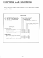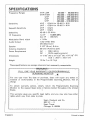
1
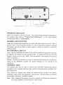
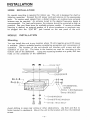
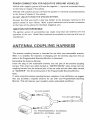
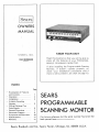
ISearsl
OWNERS
MANUAL
KNOW YOUR UNIT
MODEL NO .
Read this booklet so that you will be able to
enjoy all the features of your PROG RAMMABLE SCANNING MONITOR.
934.36390600
If after installing t he Programmable Scaning
Monitor, if doesn't operate properly, recheck your installation procedures and if
there is still a problem, see chart on page 10.
INDEX
Page
Explanation of Features
and Controls .. . ... . ... .
• Operation. . . . . . . . . . . . .
• Installation... .•. . . . . . . .
Antenna Coupling
Harness. . . . . . . . . . . . . . .
Official National Ten
Code Signals. . . . . . . . . . .
General Directions. . . . . .
Schematic Diagram. . . . . .
Symptoms and Solutions ..
Specifications. . . . . . . . . .
Warranty. . . . . . . . . . . . . .
3
4
5
6
7
8
10
11
11
SEARS
PROGRAMMABLE
SCANNING MONITOR
For future reference list the serial number found on th~
back pannel here _ _ _ _ _ __
Sears, Roebuck and Co., Sears Tower, Chicago, ILL. 60684 U.S.A.
WARNING: TO PREVENT FIRE OR SHOCK HAZARD, DO NOT
EXPOSE THIS APPLIANCE TO RAIN OR MOISTURE.
EXPLANATION OF FEATURES AND CONTROLS
CHANNEL INDICATOR
VO LUME
ON/OFF SWITCH
SQUELCH CONTROL
AUTO/MAN UAL SWI TCH
VOLUME ON/OFF SWITCH
Turn clockwise to apply power to the unit and then adjust for desired sound level.
SQUELCH CONTROL
Th is control cuts off or el iminates annoying background noise in the absence of an
incoming signal. Turn fully counterclockwise then slowly clockwise until the
scanning monitor noise d isappears. Any signal to be received must now be slightly
stronger than the average received noise. Further clockwise rotation will increase
the threshold level wh ich a signal must overcome in order to be heard. Only strong
signals will be heard at a maximum clockwise setting.
CHANNEL INDICATOR LIGHTS
The indicator lights (l ight emitting diodes) show which channel is "on" at any
particular instant.
During automatic scan operation, these lights will flash in
sequence from left to right until a signal is received on one ot the channels.
-1 -
.
•••••••••
EX TE RNAL
SPEAKER JACK
GRO UN D TERM INAL
AC POWER SOCKET
DC POWE R SOCKET
PROGRAM CARD SLOT
Insert your program card into this slot. For programming desirable frequencies on
the program card refer to "Program Card Programming" in the other booklet
provided and titled as "CODE BOOK",
CHANNEL SKIP BUTTONS
These skip buttons are provided to turn each individual channel on or off. When a
button is set to the off position (button in), the corresponding channel is sk ipped
(by-passed) and will not flash or receive signals in either the manual or automatic
scanning mode.
AUTO/MANUAL SWITCH
Auto: Set the Aoto/Man ual switch to the AUTO position for automatic scanning.
In addition, the receiver must be squelched ON. To squelch ON the unit, turn the
Squelch control until all the "noise" from the speaker is eliminated and scanning
action is obtained.
Manual: Activate the channel you want to monitor and then set the Auto/ Manua l
switch to the MANUAL position for manual selection of the channel to be
monitored.
ANTENNA JACK
The antenna jack may be used to connect the VHF-UHF telescop ing antenna
provided, or for increased I istening range, outdoor-type antennas are available from
your Sears store.
Your choice of antenna type should be determined by location and service
conditions under which the equipment will be used. Various types of antennas
are available (optional). See Sears' display.
Note:
When installing the antenna, be sure to recheck all fittings and connectors
for proper assebmly to avoid shorts or open circuits.
-2-
EXTERNAL SPEAKER JACK
You can connect an external speaker (8 ohm) to this jack for remote listening
(Built-in speaker is then disconnected automatically) .
AC POWER SOCKET
Can accept 120V AC.
DC POWER SOCKET
Connect the Red wire to the Positive (+) side of 12V DC power supply or battery
and the Black wire to the Negative (-) side. Before attempting this, be sure to read
"Installation" instructions.
OPERATION
1. Set all CHANNEL SKIP BUTTONS to on position (button out).
2. Turn SQUELCH CONTROL fully counterclockwise.
3. Turn power "on" by rotating VOLUME ON/OFF SWITCH clockwise.
4. While no signal is being received, adjust SQUELCH CONTROL clockwise until
the rushing background noise stops. Do not turn SQUELCH CONTROL any
further clockw ise than the point required to stop the background noise. To do
so will decrease the receiver's signal pick -up sensitivity.
After SQUELCH
CONTROL is adjusted properly, the receiver will now scan and operate normally
in the manual or the automatic mode.
5. SCANNING MANUAL: Check to see that AUTO/MANUAL SWITCH is down
Then select the channel desired by pressing MANUAL CHANNEL SELECTOR
SWITCH momentarily one or more times until the desired channel is obtained.
A CHANNEL INDICATOR LIGHT will indicate th e channel that has been
activated .
AUTO: Check to see that AUTO/MANUAL SWITCH is up. The receiver will
automatically switch to each channel in sequence. Scanning wil l continue until
an activated channel is received . The receiver will not scan if the squelch is
decreased to the point where noise is present.
To advance from a channel that is being received the CHANNEL SKIP BUTTON
must be pushed in . Th is Button must then be reset to the "NOR MAL" position
to avoid skip.
If it is desired to by-pass one or more channels in the scanning sequence,
CHANNEL SKIP BUTTONS for the undesired channels should be set in the off
position (button in).
This feature is useful when one of the channels being
received is from a continuous transmission type station such as the national
weather service. CHANNEL INDICATOR LIGHT only shows on the channels
where the CHANNEL SKIP BUTTON has been set in the "NORMAL" position.
-3-
INSTALLATION
HOME
INSTALLATION
No special mounting is required for indoo r use. The unit is designed for shelf or
table·top operation. Connect the AC power cord and antenna to the appropriate
jacks. To receive weak signals from a distant station, an outdoor-type external
antenna may be required. An antenna tuned to the desired f requency bands is
recommended. For best performance, the antenna shou Id be mou nted as high as
practical. See your Sears store for available antenna models. If remote or private
listening is desired, an external speaker of 8 ohms impedance or earphone may
be plugged into the "EXT SP" jack located on the rear panel of the unit.
MOBILE
INSTALLATION
Mounting
You can install this unit in any location where 12 volts negative ground DC power
is available. Select a suitable location considering appearance and convenience of
operation . The location of the unit should not interfere with proper and safe
operation of your car. The holes in the bracket are used for mou nting to the
bottom side of the dashboard.
Using the mounting bracket as a guide, drill two
holes on the underside of the dashboard.
-«-<--5mm~ NUT
tal
k ~
=1
W
I~
~DAS HBOARD
//
/
-
.../-@-®
-~
-:: ........... W-.: 1j1U- \'
/
~
<lIaaoo a Cl>oooooo
~ @!-
fl ~
.~
\ \
=>
THUMBWHEEL
SCREW
6mm¢ LOCKWASHER
6mm¢ WASHER
"'---- 5mmQ\ WASH ER
"'----. 5mmQ\SPRING WASHER
~ 5mmQ\ x 16mm BOLT
Avoid drilling in areas near wiring or other obstructions. Use Bolt and Nut to
fasten bracket to dashboard. Mount the unit to the bracket with four thumbwheel
screws.
-4-
POWER CONNECTION FOR NEGATIVE GROUND VEHICLES
Vehicle with negative ground will have the negative (-) terminal connected directly
to the frame or chassis of the veh icle.
Vehicles with positive ground will have the positive (+) terminal connected directly
to the frame of chassis of the vehicle.
DO NOT USE WITH POSITIVE GROUND SYSTEM.
Connect the Red wire (with in-line fuse holder) to the Accessory terminal on the
ignition switch of your vehicle. Make a good mechanical and electrical connection
to the frame of the vehicle for the Black (negative) wire.
IGNITION INTERFERENCE
The ignition system of automobiles may create noise that will interfere wi+h the
operation of the unit. Noise filters (optional) are available to eliminate this type of
interference.
ANTENNA COUPLING HARNESS
The antenna coupling harness is intended for use with your automobile antenna.
When it is installed, the necessity of changing over the antenna plug from the car
radio to the Programmable Scanning Monitor is eliminated.
Connecting the Antenna Harness:
Insert the plug of the sutomobile antenna into the jack of the antenna coupling
harness. Then insert one cable marked as "AM/FM RADIO" when comes from the
coupling harness into the antenna jack of the car radio and the other cable marked
as "SCANNER" into the antenna jack of the Programmable Scanning Monitor.
Note:
If, when using the antenna coupling harness, reception is not satisfactory we suggest
that you purchase a separate antenna for use with your Programmable Scanning
Monitor. This will improve your reception under weak signal conditions.
TO CAR ANTENNA
~~--r(I--~
.. ~ (
~
~
.
~
+-~(
TO PROGRAMMABLE SCANNING
MONITOR ANTENNA JACK
-5-
J~---
OFFICIAL NATIONAL TEN CODE SIGNALS
TH E LAW
concerning possession and
use of monitor receivers is embodied in
Federal regulations based on Section 605 of
the Communications Act of 1934.
This FCC regulation does not prohibit
listening to Public Service Band frequencies.
It does prohibit persons from making use of
information heard on Public Service Bands,
for private gain.
Some State laws prohibit the use of mobile
monitors except by authorized vehicles.
OFFICIAL NATIONAL TEN CODE SIGNALS
10·0
10-1
10-2
10·3
10-4
10·5
10-6
10·7
10·8
10-9
10·10
10·11
10·12
10·13
10·14
10-15
10·16
10·17
10·18
10·19
10·20
10-21
10·22
10-23
10-24
10-25
10·26
10·27
10-28
10·29
10-30
10·31
10·32
10-33
10-34
10-35
10·36
10-37
10-38
10·39
10-40
Caution
Unable to copy·change location
Signals good
Stop transmitting
Acknowledgement
Relay
Busy-stand by unless urgent
Out of service (Give location and or
telephone number)
In service
Repeat
Fight in progress
Dog case
Stand by (Stop)
Weather and road report
Report of prowler
Civil disturbance
Domestic trouble
Meet complainant
Complete assignment quickly
Return to ....
Location
Call ... by telephone
Disregard
Arrived at scene
Assignment completed
Report in person to (Meet)
Detaining subject expedite
Drivers license information
Vehicle registration information
Check records for wanted
Illegal use of rad io
Crime in progress
Man with gun
Emergency
Riot
Major crime alert
Correct time
Investigate suspicious vehicle
Stopping suspicious vehicle (Give station complete description before stop·
ping).
Urgent-use light and siren
Silent run no light or siren
10-41
10·42
10-43
1044
1045
1046
1047
1048
10-49
10-50
10·51
10-52
10-53
10·54
10·55
10·57
10·58
10·59
10-B0
10-Bl
10-B2
10·63
10·64
10-B5
10·66
10-67
10-B8
10·69
10-70
10-71
10·72
10-73
10·74
10-75
10-76
10-77
10·78
10·79
10-80
10-81
10-82
10·83
-6-
Beginning tour of duty
Ending tour of duty
Information
Request permission to leave patrol
for ...
Animal carcass in ... lane at
Assist motorist
Emergency road repairs needed
Traffic standard needs repairs
Traffic light out
Accidient-F .Pl.PD
Wrecker needed
Ambulance needed
Road blocked
Livestock on highway
Intoxicated pedestrian
Hit and run·F. PI. PD
Direct traffic
Conveyor escort
Squad in vicinity
Personnel in area
Reply to message
Prepare to make written copy
Message for local delivery
Net message assignment
Message cancellation
Clear to read net message
Dispatch information
Message received
Fire alarm
Advise nature of fire (Size type and
contents of building)
Report progress on fire
Smoke report
Negative
In contact with
En Route
ET A (Estimated Time of Arrival)
Need assistance
Notify coroner
Chase in progress
Breathalyzer repo rt
Reserve lodging
Work school xing at ...
10-84
10-85
10-86
10-87
10-88
10-89
10-90
10-91
If meeting ... advise ETA
Delayed due to ...
Officer operator on duty
Pick up checks for distribution
Advise present telephone number of .. .
Bomb threat
Bank alarm at ...
Pick up prisoner subject
10-92
10-93
10-94
10-95
10-96
10-97
10-98
10-99
Improperly parked vehicle
Blockade
Drag racing
Prisoner subject in custody
Mental subject in custody
Check (Test) signal
Prison or jail break
Records indicate wanted or stolen
GENERAL DIRECTIONS
The SEARS Programmable Scanning Monitor should be installed where the ventilation is adequate. Should it be mounted elsewhere, care shoul be taken to avoid
areas of excessive he rat which may damage components. For optimum performance
of your equipment, install and handle with care as instructed. The finest equipment
will not perform efficiently if installed and operated improperly.
Avoid leaving Program Cards under direct sunlight such as dashboad or seat.
Note: Pages 8-9 are the schematic, available in a
separate hi-res scan here.
-7-
SYMPTOMS AND SOLUTIONS
Before returning set for a malfunction be sure to check this chart for
solutions check.
SOLUTIONS
Th is set requ ires at least 12.1 volts
ON/OFF Switch and Volume
D .C. input, but for best p erformance
Power Cord Connec tion
13.8 volts D .C. is neede d (a fully
Power Cord Fuse
Squelch Cont rol is Set Properly
charged car battery).
Antenna Condition
Auto/ Manual switch (Set to
Auto position)
Cha nnel skip button
SYMPTOMS
Defective Receive
Channel light won't lig ht-up
0
0
0
No noise can be heard
0
A clear sou nd can't be heard
0
0
General Defects
Won't scanning channe I light properly-
0
Won't receive right cha nnel
0
Stop the channel light f o r n o i s e -
)
0
0
0
- 10-
SPECIFICATIONS
Frequency Ranges
Sensitivity
Sequelch Sensitivity
Selectiv ity
I F Frequency
Modu lation Band w idth
Audio Output
Speaker
Antenna impedance
Power Requirement
OimeQsions
Weight
VHF LOW
30.000 - 50.000 MHz
VHF HIGH
150.000 - 170.000 MHz
UHF
450.000 - 469.995 MHz
UHF
470.000 - 489.995 MHz
UHF
490.000 - 510.000 MHz
VHF
0.5pV fo r 10 dB S + N/N
UHF
0.8pV for 10 dB S + N/N
VHF
0.6pV
UHF
0.8pV
45 dB (± 25 KHz)
10.695 MHz
1st IF
2nd IF : 455 KHz
± 7 KHz
1.5W (THO 10%)
2W (Maximum)
3-1/8" (S cm). S ohm
50 ohm (Antenna jack)
AC
120V,60Hz
OC
13.SV negative grou nd
11·7/16" (W) x 3·11/32" (H) x 9·1/16" (0)
(S.5 x 29.0 x 23.0 cm)
10 Ibs 7 oz (4.7 kg)
These specifications are average values and not necessari ly measu reable.
~~-=---=~~~=WARRANTY ="
" ~~~~~~==~~
FULL ONE YEAR WARRANTY ON PRO GR AMMABLE
SCANNING MONITOR .~.
For one year from the date of purchase, Sears will repair any defect in
• mater ial or workmanship in the Programmable Scanning Monitor, free of "
charge. "
~
To o btain warranty service, simply return the Programm able Scanning
Monitor to the nearest Sears store or Service Center throughout the United
States.
"L
This warranty gives you specific legal rights, and you may also have other
rights which vary f rom state to state.
•
•
• ""
Sears, Roebuck and Co .
BSC 41 - 3
Sears Tower
".~"""===~=""""=c=x""",,,,,,,,,,,,,,,,,C,,"h, ,i ca, ,oO<g,"0,oc'""IL=6""0""6""S4==="""",,,,,,,,,,=,,,,,,,,~
1'76488 12
Printed in Japan