1
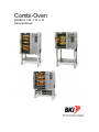
Combi-Oven
MODELS 1.06, 1.10, 2.10
Service Manual
Warranty Information
Your new BKI Combi has a 12 month factory warranty covering oven cabinet and parts. However, heating
elements in oven chamber are guaranteed for 24 months.
The factory warranty does not include glass parts, including glass in oven door, glass cover, bulbs and
door gasket.
Moreover, the factory warranty will terminate upon:
•
Errors that can be assigned to irregular installation e.g. electricity, water/drain, air exhaust,
according to BKI's current installation and service manual.
•
Errors and interruptions of operation resulting from irregular operation according to the directions
in the user's manual.
Combi-Oven
Table of Contents
Table of Contents
Table of Contents........................................................................................................................................ 1
Introduction ................................................................................................................................................. 2
Description ................................................................................................................................................ 2
Safety Precautions.................................................................................................................................... 3
Installation ................................................................................................................................................... 4
Unpacking the Oven ................................................................................................................................. 4
Positioning of oven ................................................................................................................................... 5
Water Connection ..................................................................................................................................... 5
Exhaust ..................................................................................................................................................... 6
Electrical Connection ................................................................................................................................ 6
Drain Connection ...................................................................................................................................... 7
Adjusting Flaps ......................................................................................................................................... 8
Setting System Options for CVC Controller.............................................................................................. 9
Setting System Options for S Controller................................................................................................. 10
Setting System Options for VS Controller .............................................................................................. 15
Initial Checks and Adjustments............................................................................................................... 17
Maintenance .............................................................................................................................................. 18
Scheduled Maintenance ......................................................................................................................... 18
Troubleshooting ...................................................................................................................................... 21
Replacement........................................................................................................................................... 25
Replacement Parts.................................................................................................................................... 26
Assemblies.............................................................................................................................................. 26
Accessories............................................................................................................................................. 53
Notes .......................................................................................................................................................... 57
1
Combi-Oven
Introduction
Introduction
We congratulate you on your new BKI Combi.
By the purchase of a BKI Combi, you now possess one of the market's leading oven products for
professional kitchens. All BKI Combis are currently subjected to intensive product development that
ensures that the products are always based on the latest technology as well as the most modern and
energy-saving techniques of preparation.
Moreover, the products from BKI are up-to-date with the latest development/technology as regards:
•
•
•
•
ERGONOMICS AND SAFETY
SIMPLE AND LOGICAL OPERATION
EASY-TO-OPERATE DESIGN
RELIABILITY AND SERVICE
To ensure our customers an optimum and reliable product, prior to dispatch, all BKI Combis have passed
through an extensive test programme in which all functions are subjected to a continuous and extreme
load.
Before use and to make the best use of the many facilities and advanced technique of the BKI Combi, it is
important that you are aware of working ranges and possibilities of application of the steamer. We thus
recommend you study the user's manual thoroughly before using the steamer. By this, you can - as a
user - make sure that you achieve optimum cooking results through appropriate and safe operation. By
going through the user's manual, you will save time
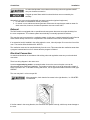
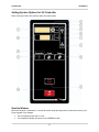
Description
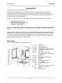
Refer to illustration below for a description of the unit.
(A)
(B)
(C)
(D)
(E)
(F)
(G)
(H)
(I)
(J)
(K)
(L)
(M)
(N)
(O)
(P)
(Q)
(R)
2
Oven door
Operating panel
2-step safety handle
Rethermalize on High Speed only!
Plug for core temperature probe
Serial plate
Risk of fire - space oven a
minimum of 2 inches from the rear
and side wall
Drip tray
Ball valve for hand shower
Hot surface
Exhaust
Cover for electric parts
Hand shower
Core temperature probe
Drain
Risk of electric shock. Disconnect
power before servicing
Stand
Adjustment legs
Combi-Oven
Safety Precautions
Always follow recommended safety precautions listed in this manual. Below is the safety alert symbol.
When you see this symbol on your equipment, be alert to the potential for personal injury or property
damage.
Safety Signs and Messages
The following Safety signs and messages are placed in this manual to provide instructions and identify
specific areas where potential hazards exist and special precautions should be taken. Know and
understand the meaning of these instructions, signs, and messages. Damage to the equipment, death or
serious injury to you or other persons may result if these messages are not followed.
This message indicates an imminently hazardous situation which, if not avoided,
will result in death or serious injury.
This message indicates a potentially hazardous situation, which, if not avoided,
could result in death or serious injury.
This message indicates a potentially hazardous situation, which, if not avoided,
may result in minor or moderate injury. It may also be used to alert against
unsafe practices.
This message is used when special information, instructions or identification are
required relating to procedures, equipment, tools, capacities and other special
data.
Specific Precautions
Risk Of Electric Shock Disconnect Power Before Servicing
For Continued Protection Against Risk Of Fire And Electric Shock, Replace With
Fuses Of Same Rating
Rethermalize on High Speed only!
Hot surface can cause severe burns. Do not touch.
Replace Oven Halogen Lamps with 12V, 20W maximum
3
Combi-Oven
Installation
Installation
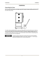
Unpacking the Oven
The oven is best handled while in its wrapping. Use a lifting trolley whenever possible. Introduce the lifting
trolley under the lower cross tube of the stand and place a couple of wooden blocks between the cross
tube and the lifting trolley.
To achieve the best possible balance, introduce the lifting trolley from the front of the oven or from the
motor side. Note that the oven can be lifted off the stand. Remove the original packaging from the oven.
Do not remove the foil that covers the surfaces until the oven has been installed, as the surfaces are
vulnerable to sharp objects such as tools, once the foil has been removed. Remove all protecting parts
that secure the racks in the oven compartment.
The packing must be destroyed in accordance with the rules and regulations
covering the disposal of rubbish in your country. Information on the packaging
material can be obtained from our technical department.
4
Combi-Oven
Installation
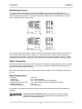
Positioning of oven
To ensure that the oven functions correctly when installed, it should be placed upright and level
(horizontally). This is measured at the front edge and side edge of the roof, and adjustment is made by
means of the adjusting screws on the stand or on the legs of table models. The height of the oven can
also be adjusted to fit the trolley for rack.
The oven should be placed at least 2 inches from the rear wall and the distance between the sides of the
oven and the nearest wall or piece of furniture, etc. should be at least 4 inches. This is to ensure the
necessary flow of cooling air to the oven. Strong sources of heat such as frying pans, fryers, etc. should
not be placed near the oven, especially not on its right side; otherwise the warranty may cease to apply.
Water Connection
As standard, the BKI Combi has one water connection. To facilitate cleaning and service, the oven should
be connected with an approved flexible 1/2" hose and the permanent installations should be fitted with a
stop-tap for the water supply to the oven.
Before connecting the oven to water, flush the water tubes thoroughly. Then fit the dirt filter and connect
the oven.
Water Requirements
Hardness:
Conductivity:
Water pressure
Water pressure Combi Clean:
Water temperature:
Chloride concentration:
max. 3 dH
min. 75 microsiemens
min. 1.5 bar (150 kP), max.6.0 bar (600 kP).
min. 2.5 bar dynamic pressure (CombiClean activated)
max. 20°C
max. 100 mg/litre
If the feeder is connected to the water distribution system with a flexible hose, this hose should be VA
approved.
A reversed osmosis plant must not be connected to ovens with a steam
generator as this may cause problems with respect to the registration of the
water level in the steam generator.
5
Combi-Oven
Installation
An authorized plumber in accordance with existing rules and regulations MUST
carry out the water connection.
Clogged up water filters and dirt in solenoid valves are not covered by the
warranty.
Alternatively, the oven can be supplied with two water connections (optional equipment):
1. for raw water for condensation nozzle (cold water)
2. for nozzle in oven cabinet and steam generator. Must meet the requirements made on water for
drain connection, however, the water temperature must not exceed 140°F.
Exhaust
The BKI Combis are equipped with an open/direct exhaust system that removes surplus humidity from
the oven compartment. The exhaust system has electrically or manually operated air exhaust.
The vent pipe can be connected to a ventilating system. In this case, a special extraction funnel is fitted to
avoid suction directly from the oven compartment. This extraction funnel can be ordered from BKI.
If an extraction hood is installed in the ceiling above the oven, it should project 50 cm over the front of the
oven. The suction effect should be 400 - 800m3/h.
The ventilation motor can be controlled directly from the oven. This means that the ventilation starts when
a program is started and runs for 5 minutes after the program is finished.
Electrical Connection
An authorized electrician in accordance with existing rules and regulations must carry out the electrical
connection.
There is a wiring diagram in the motor room.
Locate an approved plug outlet or a contact breaker close to the oven so that the oven can be
disconnected during repair and installation. The breaker must be able to cut off all poles with a length of
break of at least 3 mm. To facilitate cleaning and service, use an approved flexible connection cable, type
H05RN-F.
The oven may leak 1 mA current per kW.
After connection, check that the fan rotates in the right direction, i.e. COUNTERCLOCKWISE.
If the fan rotates in the wrong direction, the oven does not operate correctly, which may cause damage to
the oven.
6
Combi-Oven
Installation
The warranty does not cover incorrect connection.
Knock out openings for supply connection
Open type
Thread Size
Amps
Cable
2.10 - 2.14
1.16
1.10
1.06
1 1/2
1 1/4
1
3/4
70
56
42
22
2 AWG
4 AWG
6 AWG
10 AWG
Size /
opening
50.0 mm
43.7 mm
34.5 mm
27.8 mm
Drain Connection
As standard, The BKI Combi is equipped with a drain system that removes surplus water from the oven
compartment. Water may occur when steam is used in the oven and when the oven is cleaned.
An authorized plumber must carry out connection. The oven must be connected
to an open drain and the connection must end at least 20 mm above the outlet
grating or funnel.
The drain must never end directly under the oven. The drain tube must be of stainless steel, have a
diameter of at least 38 mm and a fall of at least 3° or 5%.
Never connect directly to a water trap so as to avoid obnoxious smells, bacteria
and possibly low pressure, suction or overflow.
7
Combi-Oven
Installation
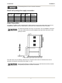
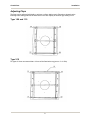
Adjusting Flaps
The flaps can be adjusted individually to achieve a uniform baking result. Experience shows that the
following basic setting produces the best result in the vast majority of cases Air gap setting in mm:
Type 1.06 and 1.10
Type 2.10
For types 2.10 we recommend that a 10 mm rail be fitted at the top (part no. O 11.588).
8
Combi-Oven
Installation
Setting System Options for CVC Controller
System options are set through Engineering menus. To access these menus press and hold the F1 key
while pressing the START/STOP key. A list of menu commands will appear in the display. To see
additional menu commands press F1. To return to the main display, press the ENTER/STEP key. To
select a command, access it’s menu then press the numeric key associated with the command. Upon
selecting a command, its options will be displayed. To select/activate and navigate the command options
use the keys specified on the display. Return to the Engineering menu by pressing F1. The following table
lists the command options that need to be set to enable proper operation of the BKI Combi.
CVC Controller System Settings
Menu Command
Option Settings
1 = TEST FUNCTION
Only used to troubleshoot oven.
2 = ENCODE OVEN TYPE
2 = Autorestart
3 = SELECT LANGUAGE
4 = GB
2 = Adjust PT100 sensors
The values are factory set by the manufacturer.
Consult manufacturer before adjusting.
3 = Set Restart Time
Leave as is
1 = Oven Light ON/OFF
1 = Oven light 5min.
2 = Phase Test
OFF
3 = Transfer all menus
Enter = OK
1 = Setup
Oven type (2 = CVC)
Temperature mode (2 = Fahrenheit)
Keyboard (2 = BKI)
Special mode (1 = Normal)
Fan (1= Single direction)
Language (4 = GB)
2 = Motor Alarm
OFF
3 = Cleaning mode
1 = Normal 2 step
1 = Access Code
OFF
2 = Warm up in step 1
Normal 6 step
3 = Condensation ON/OFF
Leave as is
4 = Show empty tray
Leave as is
9
Combi-Oven
Installation
Setting System Options for S Controller
Refer to the figure below as necessary while using this section.
10
Combi-Oven
Installation
Start-Up Window
When the computer is switched on, it checks all control lamps and segments to make sure that they work.
Figures appear in the displays:
•
•
•
The time display shows how U1 is set.
The temperature display shows the current EPROM version.
The display for core temperature shows whether the computer includes CombiClean (0 = without
CC, 1= with CC).
Accessing the Set-Up Mode
Select the set-up mode by pressing key (4) and key (2) simultaneously for 5 sec. U1 appears in the time
display. Shift to the next setting (max. U5) by pressing key (2). The set-up mode can be
interrupted/closed any time by pressing key (18).
U1: Selecting Automatic Restart, Oven Model And Voltage
Automatic restart
1 or 0 is shown in the time display (1).
0 = The oven will not restart a program that has been interrupted because of power cut.
1 = The oven will restart a program that has been interrupted because of power cut.
Shift by pressing key (3).
Oven model
A digit between 1 and 6 is shown in the program display (17).
1 = CM, 2 = CV, 3 = BM, 4 = ST, 5=S, 6=VS
Shift by pressing (17).
Voltage
1 or 2 is shown in the core temperature display (8).
1 = Voltage with 0
2 = Voltage without 0
Shift by pressing the core temperature key (9).
U2: Selecting Interior Light
When the program display (17) shows 5, the interior light is automatically switched off after 5 min.
When the program display (17) shows 0, the interior light will shine continuously.
When the program display (17) shows 6, the interior light is automatically switched off after 5 min. In
addition, the light in the oven door is switched off after 3 sec. when the door is opened.
When the program display (17) shows 1, the oven light will shine continuously. In addition, the light in the
oven door is turned off after 3 sec. when the door is opened.
Settings 1 and 6 are very useful on ovens with oven light in the door in order to avoid blinding while the
door is open.
Shift by pressing (17).
11
Combi-Oven
Installation
U3: Adjusting Temperature Sensors (Pt-100)
The digit of the sensor in use is shown in the program display (17).
1 = oven chamber, 2 = probe, 3 = steam generator, 4 = condensation
Change the digit by pressing the program key (17).
The current temperature is shown in the temperature display (5).
The set point is shown in the core temperature display (8)
Standard set point = 100, which can be adjusted downwards to 80 and upwards to 120 with the arrow
keys.
Each temperature sensor can be adjusted/corrected by approx. +/-10°C, i.e. the temperature changes in
steps of 0.5°C.
The core temperature display holds only 2 digits, consequently 80 = 80, 00 = 100 and 20 = 120.
U4: Selecting Pre-Set/Current Temperature, Combiclean, Additional
Detergent, Showdisplay And Printer
Pre-set/current temperature
1 or 0 is shown in the time display (1).
0 = Pre-set temperature (standard)
1 = Current temperature during operation
Shift by pressing (3).
CombiClean
The oven size is shown in the temperature display (5).
You change between oven sizes by pressing the temperature key (7).
Additional Detergent
If the oven chamber is not properly clean when the cleaning program is completed, it is possible to add
additional detergent.
Press the key for manual humidity (24) until the control lamp is turned on. ”Additional detergent” is now
active.
Note that the programs are prolonged by 5 minutes + the detergent phase.
If the control lamp is off, this function is off.
Demo mode
It is possible to select a demo mode in which the oven rinses only.
Press the exhaust key (19)until the control lamp is turned on.
Showdisplay
Press (17) until the display shows 1.
The control lamps in (23) and (22) flash to indicate that the keys are active.
By pressing (23), you reserve memory in the showdisplay for the 16 programs.
12
Combi-Oven
Installation
With (22), you enter a start text for each program. However, this is usually not necessary, as the
showdisplay is ready for use on delivery.
If you have deleted or ruined a program, press (9) and select the program you have just ruined and then
to enter the start text again.
Note that there should be at least 20 characters in the program on the showdisplay in order for the
start text to be transferred.
Note! When the showdisplay is active, the printer cannot be used.
Printer
Press (17), until the display shows 0. The printer output is thus activated.
Press (18) to enter the start-up menu.
Press (20) for 5 seconds. The time display now shows PR*nt, “Yes” in the temperature display and “No” in
the display for core temperature probe.
Press (6).
The printer output is now activated.
To switch off the printer output, press (9)
.
Note! When the showdisplay is active, the printer cannot be used.
U5: Selecting Phase Sequence Test And Reversing
Phase sequence test
Phase sequence test is usually always active.
This alarm can be deactivated in the case of installation for demonstration purposes in order to avoid
error code 15.
The temperature display shows either ON or OFF. ON and OFF are selected by pressing (6).
Reversing
In the reversing function, it is possible to set the time before reversing as well as the time of the interval.
Change between 0, 1 and 2 by pressing (17).
0 = “Reversing” is switched off and the time is not shown (standard)
1 = “Reversing” is switched on and error code 5 “Fan too hot” works reversely because the thermo-switch
of the motor used is open and closes when the temperature is too high.
2 = “Reversing” is switched off and error code 5 “Fan too hot” works as usual, i.e. the thermo-switch is
closed and opens when the temperature is too high.
The time during which the fan is running is shown in the time display (1) and is set between 10 and 99
with the arrow keys (4, 11). Each step corresponds to 2 seconds, it is therefore possible to set the time of
the intervals between 20 and 198 seconds (standard is 50 = 100 seconds). The time of the interval is
shown in the core temperature display (8) and is set with the core temperature key (9) and the core
temperature ON/OFF key (10).
The time can be set between 1 and 30 seconds (standard = 10 seconds).
13
Combi-Oven
Installation
S Controller System Settings
Set-Up Mode
Settings
U1
Automatic restart (1)
Voltage (1)
Oven Model (5)
U2
Interior light (5)
U3
Leave as is
U4
Pre-set/current temperature (1)
CombiClean (select your oven size)*
Additional Detergent (press manual humidity key
until lamp turns on)*
Printer (Not applicable)
U5
Phase Sequence Test (OFF)
Reversing (2)
* - Only with CombiClean models.
14
Combi-Oven
Installation
Setting System Options for VS Controller
Refer to the figure below as necessary while using this section.
Start-Up Window
When the computer is switched on, it checks all control lamps and segments to make sure that they work.
Figures appear in the displays:
•
•
The time display shows how U1 is set.
The temperature display shows the current EPROM version.
15
Combi-Oven
Installation
Accessing the Set-Up Mode
Select the set-up mode by pressing key (4) and key (2) simultaneously for 5 sec. U1 appears in the time
display. Shift to the next setting (max. U5) by pressing key (2). The set-up mode can be
interrupted/closed any time by pressing key (12).
U1: Selecting Automatic Restart
Automatic restart
1 or 0 is shown in the time display (1).
0 = The oven will not restart a program that has been interrupted because of power cut.
1 = The oven will restart a program that has been interrupted because of power cut.
Shift by pressing key (3).
U4: Selecting Pre-Set/Current Temperature
Pre-set/current temperature
1 or 0 is shown in the time display (1).
0 = Pre-set temperature (standard)
1 = Current temperature during operation
Shift by pressing (3).
U5: Selecting Phase Sequence Test And Reversing
Phase sequence test
Phase sequence test is usually always active.
This alarm can be deactivated in the case of installation for demonstration purposes in order to avoid
error code 15.
The temperature display shows either ON or OFF. ON and OFF are selected by pressing (6).
VS Controller System Settings
Set-Up Mode
Settings
U1
Automatic restart (1)
U2
Not Used
U3
Not Used
U4
Pre-set/current temperature (1)
U5
Phase Sequence Test (OFF)
16
Combi-Oven
Installation
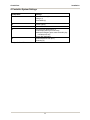
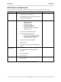
Initial Checks and Adjustments
Upon completion of the installation, perform the following to ensure proper operation of the oven.
Category
Oven exterior
Connections
Oven
compartment
Operating panel
Activity
• Check that the oven has suffered no transport
damages (dents, scratches, etc.)
•
Check/adjust height and check that the oven is
placed level (horizontally)
•
Check for correct water connection
o open water supply
o check for leaks
o close water supply
o check and clean dirt filter
o reopen water supply
o check hand shower and stop tap
(under the oven)
•
Check correct electrical connection
•
Check correct drain connection
o check correct mounting of drip tray
o check correct fall of hose from drip
tray, and examine for leaks
•
Check correct exhaust connection
•
Clean the oven
•
Apply the steel oil which is delivered with the
oven
Check the direction of rotation of the fan
•
•
Check that the filter housing is mounted
correctly
•
Check interior light
•
•
Clean the oven
Check and adjust, if necessary, each of the
pre-set values
•
Heat up the oven to 482°F for approx. 5 min.
17
Date Performed
Combi-Oven
Maintenance
Maintenance
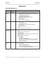
Scheduled Maintenance
Category
Entire Unit
Oven
exterior
Perform
Daily
Annually
Activity
Cleaning (Refer to cleaning procedure)
•
•
Connections
Annually
•
•
•
Oven
compartment
Annually
•
•
•
•
•
•
Operating
panel
Annually
•
•
Oven door
o check that hinges are firmly fixed and that the oven door is
fitted straight in relation to the oven
o check door sealing for cracks
o check/adjust 2-step door handle
o check/adjust inductive sensor/door switch
Exhaust plug/vacuum valve
o Check for leaks
o Check for/remove scale deposits
Water connection
o check for leaks
o check and clean dirt filter
o check hand shower and stop tap (under the oven)
Electric connection
o check for irregularities
Exhaust
o check/adjust exhaust plate and motor
Check that the fan has been correctly fixed and that it rotates
freely
Check/adjust filter housing and flaps
Check interior light
Check/adjust rack and trolley for rack to ensure that the height of
the oven is correct
Check nozzle for correct dispersion
Heating elements
o check gaskets
o check/tighten heating elements
o start the oven, activate the mode HOT AIR for a couple of
seconds, then turn off the oven and check that all heating
elements are lukewarm
Test each program for a short period
Check temperature
o set the oven at HOT AIR, 338°F
o set the oven at STEAMING, 212°F
o check the oven temperature with a digital thermometer that
has been thoroughly tested and approved.
18
Combi-Oven
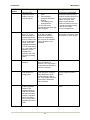
Category
Under the
oven
Maintenance
Perform
Annually
Activity
•
•
•
•
In motor
compartment
Annually
•
•
•
•
•
•
•
Solenoid valves
o check hoses
o clean solenoid valves
o check that solenoid valves close
Check/test drain pump
Drain
o check for leaks in drain system
o check that drain system is not blocked
o Check condensation nozzle in drain tube
Drip-tray system
o check/adjust drip-tray springs
o check drain basin and hose from drip tray
o check correct fall of hose
o check passage in hose (clean out hose, if necessary)
Heating elements for oven compartment
o check insulation for leaks
o check for electric leakage ("megges")
o check load distribution on phases
Steam generator
o check for leaks
o check for electric leakage in heating elements ("megges")
o check load distribution (idling) on phases
o check rubber gaskets at heating elements
o check/tighten heating elements
o check/adjust level sensors
o descale steam generator
Check/tighten copper tube connections
Check/tighten all electric connections
Contactors
o check that there are no bad connections
o check that all components are firmly fixed
Check/test motor for damper in air exhaust
Fan motor
o check that the motor is firmly fixed
o check direction of rotation
o check gasket at motor shaft
19
Combi-Oven
Maintenance
Cleaning
The construction of the BKI Combi makes it very easy to clean. The oven compartment is all-welded in
stainless steel and accordingly splash proof. You will find the easy-to-use hand shower with flexible hose
very suitable for inferior cleaning.
The door gasket at the oven door can easily be removed which ensures a quick and efficient cleaning
around it
The flat front panel also makes the exterior cleaning quick and efficient.
1. Interior cleaning
Manual Method
a.
Always clean the oven when it is cold or cool the oven compartment down to below 140°F.
b.
Add mild or strong oven detergent (according to requirement) with a soft brush to the sides of
the oven compartment, rack etc. Protect your face and hands as the oven detergent may be
caustic.
c.
Leave the oven detergent for approx. 5-10 min.
d.
With the MULTI STEAMING mode, the oven is set to steam for approximately 10 min. at
194°F.
e.
Flush the oven compartment with the hand shower.
f.
Check that the water can pass freely through the drain. The grating that comes with the oven is
to be placed over the drain hole inside the oven.
Integrated Cleaning Program (CVC and S Controllers only)
a.
Choose the cleaning program (“198” for CVC controller and “C” for S controller). The display
says “CLEA”.
b.
Press “START”.
c.
Apply an oven detergent with a soft brush or a sprayer when the alarm sounds and the display
says ”SOAP”.
d.
Close the oven door.
e.
When the alarm sounds and the display says ”AQUA”, rinse the oven chamber with the hand
shower.
Never use high-pressure cleaner. Never spray water directly on heating
elements behind the filter housing.
2. Cleaning behind filter housing
For a more thorough cleaning of the oven compartment, the filter housing is removed so that it is
possible to clean at the fan and the heating elements. You loosen the 2 screws (A) and (B) on the
filter housing. The filter housing is demounted by lifting it up till it is clear of the bottom pin and then
tipping it.
20
Combi-Oven
Maintenance
3. Cleaning of Nozzle
The water nozzle can be dismounted and cleaned according to needs. The easiest way of cleaning
the nozzle is by soaking it in scale remover for approx. 6-8 hours. When remounting the nozzle, note
that the small notch will turn upwards, see the figure below.
4. Exterior Cleaning
The oven cabinet is washed with soapy water and then dried with a soft and moist cloth. After drying,
steel oil is to be added (refer to directions on the packing). Note! The exterior of the oven is never to
be flushed with water hose or high-pressure cleaner which may damage the electronic components.
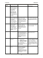
Troubleshooting
Error Codes
The BKI Combi ovens have an automatic error detecting system. In the event of malfunctioning of the
oven or faulty connection, error codes (for S or VS controller) or messages (for CVC controller) appear in
the display. This means that any defects are specified immediately and can be remedied quickly and
efficiently, which again means fewer interruptions of operation and thus fewer service calls. The following
list of error codes provides you with a brief description of each error code and an indication as to how the
fault can be remedied.
Error Code
Number
1
Error Message
Possible Cause
Remedy
Program switch
defective
The program switch has
been turned beyond stop
position.
Replace computer.
3
Faulty connection
4
Oven chamber above
305°C
Reconnect terminals 2 and 21
in plug S2.
The temperature circuit
breaker for the oven
compartment has gone. The
oven cannot be operated
until the defect has been
remedied.
21
Reconnect the thermostat that
is located in a hollow under the
oven on the left-hand side of
the front panel, by pressing the
red button gently. Note that the
thermostat may be
disconnected during transport.
Combi-Oven
Error Code
Number
5
Maintenance
Error Message
Possible Cause
•
Remedy
Fan is hot (The
temperature circuit
breaker in the fan
motor has gone.)
Breaking of phase /
fuses
• Fan blocked by
incorrectly fitted filter
housing
• Fan rotating in the
wrong direction
The oven cannot be
operated until the defect has
been remedied.
Check fuses in switchboard.
Check that the filter housing
has been correctly fitted on the
pins. Let the oven cool for
approx. 20-30 min., then
restart it. Check that the
direction of rotation of the fan
is counter-clockwise (looking
at the fan from inside
the oven compartment).
6
Drain temperature
above 75 °C (The
drain temperature is
normally kept below
60°C by means of the
built-in condensation
nozzle. If the drain
temperature exceeds
75 °C for more than 5
min., error code 6 will
appear for a short
moment at the
beginning and at the
end of the operating
mode.)
Dirt in solenoid valve, nozzle
or dirt filter, hot water
connected or defective
sensor for condensation.
The oven can be operated
even if the defect is not
remedied.
Check that the oven is
connected to cold water. Clean
solenoid valve, nozzle or filter.
7
Oven sensor
defective
The temperature sensor in
the oven chamber is
defective. The oven cannot
be operated until the defect
has been remedied.
Replace sensor.
8
Core temperature
probe defective or
wrongly fitted
Probe is not fitted in socket.
Probe defective, socket for
probe defective or shortcircuited (due to water or
fat). The program cannot be
used until the defect has
been remedied.
Check that the probe is
correctly fitted or clean the
socket.
9
Temperature sensor
in steam generator
defective (The
program cannot be
used until the defect
has been remedied.
However, programs
that do not require
the use of the steam
generator can still be
used.)
Replace heating element with
sensor.
22
Combi-Oven
Error Code
Number
10
Maintenance
Error Message
Possible Cause
Remedy
Replace sensor.
Condensation sensor
defective (The oven
can still be operated
even if the defect is
not remedied.
However, the
temperature in the
drain will exceed
60°C and the defect
should therefore be
remedied as soon as
possible.)
11
Water shortage in
steam generator (The
maximum water level
in the steam
generator has not
been reached after 2
minutes of filling.)
Solenoid valve or dirt filter
clogged, water supply
blocked or water pressure
too low (min. 1.5 bar). The
program cannot be used
until the defect has been
remedied.
Clean solenoid valve or dirt
filter. Check the water supply
to the oven. Check that the
water pressure is min. 1.5 bar.
13
Temperature in
steam generator
above 130 °C
(The temperature of
the upper heating
element in the steam
generator is above
130°C.)
Water shortage in steam
generator or scale on
heating elements. The
program cannot be used
until the defect has been
remedied.
Stop the oven for approx. 5
min., then resume the program
that was interrupted.
14
Breaking of phase
One or more phases in the
power transmission to the
oven is lacking, possibly due
to a defective fuse. The
program cannot be used
until the defect has been
remedied.
Check switchboard. Replace
defective fuses, if any.
15
Incorrect phase
sequence
Fan rotates in the
wrong direction.
• 2 phases in the electric
installation have been
exchanged by mistake.
The oven cannot be
operated until the defect has
been remedied.
Change about the 2 phases in
the electric installation. Let the
oven cool for 20-30 min., then
restart it. Check that the
direction of rotation of the fan
is counter-clockwise (looking
at the fan from inside the oven
chamber).
16
Wiring defect at door
switch
Wire for door switch shortcircuited or interrupted.
Cancel the message by
pressing any key reappears when the oven is
restarted. The oven can be
operated even if the defect is
not remedied.
Replace door switch.
•
23
Combi-Oven
Maintenance
Test Functions
Certain Combi functions can be tested via the controller. This section explains how to access these
functions and details what functions are available for each type of controller.
Accessing Test Functions with CVC Controller
To access the Test Function command, press and hold the F1 key while pressing the START/STOP key.
A menu will appear showing the Test Functions command. Simply press the numeric 1 key to execute this
command. The Test Functions display will appear and allow you to select/activate and navigate all the
test functions. Return to the Test Function command by pressing F1. To return to the main display, press
the ENTER/STEP key.
Accessing Test Functions with S Controller
To access the Test Functions press the up arrow key and the Time keys simultaneously for 5 sec. The
time display shows the Test Function number (ex. dd 1). Navigate the functions by pressing the up and
down arrow keys. The test functions can be interrupted/switched off any time by pressing the Storage key
key. The output can be switched on and off constantly by pressing the ON/OFF key, or you can switch the
output on and off by pressing the Manual key.
List of Test Functions
Number
Description
Controller without
this feature
Comments
dd:
1
Oven heat
dd:
2
Steam generator heat
dd:
3
Fan low
dd:
4
Fan high
dd:
5
Motor brake
dd:
6
Injection valve
dd:
7
Flooding valve
S, CVC
dd:
8
Drain pump
S, CVC
dd:
9
Condensation valve
dd:
10
Damper motor
dd:
11
Exhaust
dd:
12
Special Function
dd:
13
Buzzer
dd:
14
Interior light
dd:
15
Oven sensor
Shows °C or Err if a defect occurs
dd:
16
Core temperature sensor
Shows °C or Err if a defect occurs
(core temperature probe missing)
S, CVC
Can only be active when the fan is
on
Can only be activated if there is
water in the generator
To be active for max. 5 sec. only
Works only if an external unit has
been connected
Loud continuous sound when
ON/OFF is activated
24
Combi-Oven
Maintenance
Number
Description
Controller without
this feature
Comments
dd:
17
Steam generator sensor
S, CVC
Shows °C if Err if a defect occurs
dd:
18
Condensation sensor
dd:
19
Motor Speed
dd:
20
Oven door
dd:
21
Water level in steam
generator
dd:
22
Thermal cutout, 305°C
dd:
23
Thermal cutout, fan motor
dd:
24
Contacts in damper motor
Shows °C or Err if defect occurs
S, CVC
Shows a symbol for door open or
closed and Err if a defect occurs.
Can be initialized by pressing
exhaust key if door is closed and
oven sensor normal
Shows water level below min. and
max. Temperature key: water in )
CM and Core temperature key:
water out) ST
ON appears if OK, OFF if
interrupted or a wiring defect has
occurred
ON appears if OK, OFF if
interrupted or a wiring defect has
occurred
ON appears when the contacts
are connected and OFF if
interrupted
Replacement
Changing halogen lamps in oven compartment
Replace Oven Halogen Lamps with 12V, 20W maximum.
Remove the lamp glass by means of a screwdriver. Always use halogen lamps specially made for BKI
Combis. Never touch the lamp without first protecting your fingers with gloves or a piece of cloth.
25
Combi-Oven
Replacement Parts
Replacement Parts
Use the information in this section to identify replacement parts. To order replacement parts, call your
local BKI sales and service representative. Before calling, please note the serial number, model number
and voltage on the rating tag affixed to the unit.
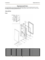
Assemblies
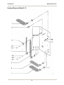
Door
POS
1
1
1
1
1
1
TYPE
1.06
1.08
1.10
1.12
1.16
1.20
QTY
1
1
1
1
1
1
BKI PART NO
GL0295
GL0296
26
DESCRIPTION
Interior glass
Interior glass
Interior glass
Interior glass
Interior glass
Interior glass
Combi-Oven
POS
1
1
IA
1B
2
3
3
3
3
3
3
3
4
4A
5
5
5
5
5
5
5
5
6
7
8
9
10
11
11A
12
13
13
13
13
13
13
13
13
14
15
16
16A
16B
Replacement Parts
TYPE
2.10
2.14
All
All
All
1.06
1.08
1.10
1.12
1.16
2.10
2.14
All
All
1.06
1.08
1.10
1.12
1.16
1.20
2.10
2.14
All
All
All
All
All
All
All
All
1.06
1.08
1.10
1.12
1.16
1.20
2.1 0
2.14
All
All
All
All
All
QTY
1
1
2-4
2-4
l
1
1
1
1
1
1
4
4
1
1
1
1
1
1
1
1
4
4
4
2/4
2/4
2/4
2/4
2
1
1
1
1
1
1
1
1
4
4
4-6
1
1
BKI PART NO
GL0297
HN0309
HN0310
H0137
DF0299
DF0300
DF0301
WSH265
F0181
GL0292
GL0293
GL0294
WSH259
SCR416
F0180
HN0311
HN0312
HN0313
HN0314
HN0315
G0307
G0308
G0309
HN0316
F0361
HN0312
HN0318
HN0319
27
DESCRIPTION
Interior glass
Interior glass
Hinge bracket
Cap nut
Locking device, low
Door
Door
Door
Door
Door
Door
Door
Rubber washer
Nylon hose
Exterior glass, black
Exterior glass, black
Exterior glass, black
Exterior glass, black
Exterior glass, black
Exterior glass, black
Exterior glass, black
Exterior glass, black
Washer
Screw M5
Cover cap, black
Clamp
Screw
Rubber washer
Washer
Stopper, plastic
Door seal
Door seal
Door seal
Door seal
Door seal
Door seal
Door seal
Door seal
Stopper, rubber
Stopper, plastic
Screw
Screw
Piece for handle
Combi-Oven
Replacement Parts
Drip Tray
28
Combi-Oven
POS
1
1
IA
2
2A
3
4
4A
5A
5A
5B
5B
6
TYPE
1.06-1.10
2.10
All
All
All
All
All
All
1.06 -1.10
2.10
1.06 -1.10
2.10
All
Replacement Parts
QTY
1
1
1
1
1
1
4
2
1
1
1
1
2
BKI PART NO
DT0009
DT0008
DT0007
H0099
F0183
F0184
DT0005
DT0006
DT0010
DT0011
HN0312
29
DESCRIPTION
Drip tray
Drip tray
Discharge tray
Hose
Clamp
Holder
Screw
Washer
LH Drip slide
LH Drip slide
RH Drip slide
RH Drip slide
Screw
Combi-Oven
Replacement Parts
Front
30
Combi-Oven
POS
1
2
3
4
5
6
7
8
9
10
11
12
13
14
14A
14B
15
15A
16
17
Replacement Parts
TYPE
All
All
All
All
All
All
All
All
All
All
All
All
All
All
All
All
All
All
All
All
QTY
2
2
1
4
2
1
1
1
2
2
2
2
1
1
3
1
1
4
1
1
BKI PART NO
HN0300
HN0301
HN0302
HN0303
HN0304
HN0305
HN0306
HN0307
C0506
S0349
FT0535
HN0308
31
DESCRIPTION
Screw, M6
Washer
Hinge, upper
Screw, M6
Bushing
Spring
Washer, copper
Hinge, lower
Cover for catch
Screw
Washer, spring
Washer
Catch
Sensor, inductive
Plastic nut
Sealing
Stopper, plastic
Plastic plug
Socket for probe
Grating for drain
Combi-Oven
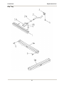
Replacement Parts
Heating Elements Model 1.06
32
Combi-Oven
POS
1
2
3
4
5
6
7
8
9
TYPE
3 x 208V
Replacement Parts
QTY
1
6
4
10
6
1
6
6
1
BKI PART NO
NZ0005
C0106
T0093
33
DESCRIPTION
Nozzle, elbow
Heating element 1300W
Pipe holder
Washer
Screw
Temperature sensor
Washer
Gasket
Washer
Combi-Oven
Replacement Parts
Heating Elements Model 1.10
34
Combi-Oven
POS
1
2
3
4
5
6
7
8
9
10
11
12
TYPE
3 x 208V
All
3 x 208V
All
All
All
3 x 208V
3 x 208V
All
All
All
All
Replacement Parts
QTY
1
1
2
4
10
10
2
1
1
6
6
1
BKI PART NO
C0103
NZ0005
C0104
C0105
C0102
T0093
35
DESCRIPTION
Heating element 1650W
Nozzle, elbow
Heating element 1650W
Pipe holder
Washer
Screw
Heating element 3300W
Heating element 3300W
Temperature sensor
Washer
Gasket
Washer
Combi-Oven
Replacement Parts
Heating Elements Model 2.10
36
Combi-Oven
POS
1
2
3
4
4A
4B
4C
5
6
7
8
8A
Replacement Parts
TYPE
3 x 208V
All
All
3 x 208V
All
All
All
3 x 208V
3 x 208V
All
All
All
QTY
2
1
8
2
9
17
17
4
1
9
1
1
BKI PART NO
C0102
NZ0005
C0104
C0105
C0103
T0093
37
DESCRIPTION
Heating element 3300W
Nozzle, elbow
Pipe holder
Heating element 1650W
Washer
Washer, spring
Screw
Heating element 3300W
Heating element 1650W
Gasket
Temperature sensor
Washer
Combi-Oven
Replacement Parts
Motor
38
Combi-Oven
POS
1
1A
2
3
4
5
6
7
8
9
10
10
10
10
10
10
10
10
11
11
11
11
11
11
11
12
12A
14
14A
15
16
16A
17
18
TYPE
All
All
All
All
All
All
All
All
All
All
1.06
1.08
1.10
1.12
1.16
1.20
2.10
2.14
1.06
1.08
1.10
1.12
1.16
1.20
2.14
All
All
All
All
All
All
All
11
All
Replacement Parts
QTY
1
1
8
4
1
4
1
1
1
1
1
1
1
1
1
2
1
1
4
4
4
4
4
8
4
X
X
2
2
2
2
2
3
3
BKI PART NO
M0080
HN0331
HN0321
HN0322
HN0323
HN0324
HN0325
HN0320
HN0327
HN0328
39
DESCRIPTION
Fan 3 x 208V
Arrow (sticker)
Nut M8
Washer M8
Motor plate
Screw M8
Gasket
Fan
Washer MIO
Screw MIO
Filter housing
Filter housing
Filter housing
Filter housing
Filter housing
Filter housing
Filter housing
Filter housing
Flap
Flap
Flap
Flap
Flap
Flap
Flap
Screw M6
Washer
Stop plate
Stop plate
Washer
Nut
Washer, spring
Snap screw
Retainer
Combi-Oven
Replacement Parts
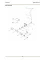
Solenoid Valve
40
Combi-Oven
Replacement Parts
POS
1
TYPE
All
QTY
2
BKI PART NO
2
3+4
5
5A
6
7
8
9
10
11
12
13
14
15
All
All
All
All
All
All
All
All
All
All
All
All
All
All
1
1
2
2
1
1
1
1
SV0011
*
All
2
4
6 ft.
2
41
DESCRIPTION
Divider 1,2 L
Solenoid valve, 2
way
Connection
Screw M4
Washer
T-connector
Ball valve
Reducing
Nipple
Elbow
Nipple, elbow
Clamp
Hose
Bracket
Screw M5
Nozzle and
cooling
Combi-Oven
Replacement Parts
Condensation/Drain
42
Combi-Oven
POS
1
1A
2
3
4
5
5
6
7
8
9
10
11
TYPE
All
All
All
All
All
1.06-1.10
2.10
All
All
All
All
All
All
Replacement Parts
QTY
5 ft
2
1
1
1
1
1
1
1
1
1
1
1
BKI PART NO
T0092
HN0339
43
DESCRIPTION
Hose
Clamp
Nipple, Elbow
Extension tube
Nozzle
Manifold
Manifold
Washer
Temperature sensor
Screw
Washer, spring
Washer
O-ring
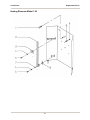
Combi-Oven
Replacement Parts
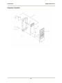
Exhaust/Vent
44
Combi-Oven
POS
1
2
3
3A
4
5
6
7
8
9
Replacement Parts
TYPE
All
All
All
All
All
All
All
All
All
All
QTY
1
1
1
1
1
2
4
2
1
2
BKI PART NO
M0081
V0021
45
DESCRIPTION
Shaft
Damper motor
Arm
Screw
Valve
Locking ring
Washer M5
Gasket
Tube for damper
Screw
Combi-Oven
Replacement Parts
Computer Controller
46
Combi-Oven
POS
TYPE
Replacement Parts
QTY
1
All
1
2
All
1
3
All
4
All
5
All
6
All
7
All
8
All
* - Shown on opposite page.
10
10
2
6
6
1
BKI PART NO
DESCRIPTION
CP0038
CP0044
CP0042
C0742
C0745
C0746
Computer CVC Model *
Computer S Model
Computer VS Model
Touch Pad CVC Model *
Touch Pad S Model
Touch Pad VS Model
Nut, plastic M3
Washer M3
Screw
Self-locking nut
Spacer
Washer, fibre
47
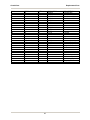
Combi-Oven
Replacement Parts
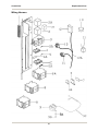
Wiring Harness
48
Combi-Oven
POS
1
2
2A
2B
3
3A
4
4A
4C
5
5
5A
6
6A
7
8
8
8A
9
9A
9B
9C
10
11
12
12A
13
14
Replacement Parts
TYPE
All
All
All
All
All
All
All
All
All
All
All
All
All
All
All
1.06 & 1.10
2.10
ALL
All
All
All
All
All
All
All
All
All
All
QTY
1
1
1-2
1-2
1
3
4
1
2
2
2
2
3
1
1
2
2
1
1
2
2
6 ft.
1
1
1
10 ft.
1.
1
BKI PART NO
TB0060
HN0334
HN0335
HN0333
FH0009
F0179
FH0011
FH0010
F0176
F0177
F0178
TB0061
R0165
R0167
R0164
T0094
B1006
49
DESCRIPTION
Terminal strip
Transformer 17V
Transformer 24V
Transformer 12V
Fuse holder
Fuse 4A
Fuse holder
Plate
Fuse holder
Fuse 0.8A
Fuse 3A
Fuse 8A
Terminal block
Stop
Plate
Contactor (K1, K2)
Contactor (K1, K2)
Contactor (K3)
Temp. circuit break
Washer
Screw
Flex hose, black
Buzzer
RC block for motor
Connector 37 pole
Spiral wrapping
Plug 12 pole
Plug 15 pole
Combi-Oven
Replacement Parts
Interior Light
50
Combi-Oven
POS
1
2
3
4
5
6
6A
6B
6C
7
Replacement Parts
TYPE
All
All
All
All
All
All
All
All
All
All
QTY
3-12
1-4
1-4
1-4
1-4
1-4
2-8
1-4
1-4
1-2
BKI PART NO
GL0287
HN0336
B0562
HN0337
51
DESCRIPTION
Screw
Lamp glass
Gasket
Halogen lamp
Lamp housing
Socket
Screw
Washer
Nut
Porcelain connector
Combi-Oven
Replacement Parts
Hand Shower and Probe
52
Combi-Oven
POS
1
2
3
4
5
6
7
7A
8
9
TYPE
All
All
All
All
All
All
All
All
All
All
All
Replacement Parts
QTY
1
1
1
2
1
2
1
6
1
1
1
BKI PART NO
HS0050
HN0338
HN0329
HN0330
C0741
HN0332
DESCRIPTION
Hand shower
Gasket
Connection
Spring for hand shower
Hose
Clamp plastic
Terminal, plastic
Screw
Probe, core temp.
Socket
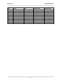
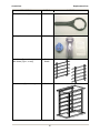
Cleaning & Accessory Kit
Accessories
DESCRIPTION
PART NO
1.10 Grid Shelf
R0094
2.10 Grid Shelf
R0095
6 Bird Chicken Rack
R0096
53
PICTURE
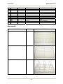
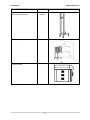
Combi-Oven
DESCRIPTION
Replacement Parts
PART NO
8 Bird Chicken Rack
R0097
Kit, Filter Housing–Clear
FX0001
Scale Stick
FX0002
Bracket Kit for Housing
FX0003
54
PICTURE
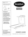
Combi-Oven
DESCRIPTION
Replacement Parts
PART NO
Wrench, Filter Housing
FX0004
Housing–Clear
FX0005
Rack Slides (Type 1.06 only)
Rack Slides (Type 1.10 only)
R0091
R0092
Rack Cassette (Type 2.10 only)
R0093
55
PICTURE
Combi-Oven
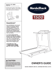
Replacement Parts
DESCRIPTION
PART NO
Rack Trolley without drip tray (shown)
Rack Trolley with drip tray
104225A
104226A
Wall Brackets
*
Extraction Hood
*
PICTURE
* - These accessories are not stocked. Call BKI Customer Service to special order this.
56
Combi-Oven
Notes
Notes
57
P.O. Box 80400, Simpsonville, S.C. 29680-0400, USA
http://www.bkideas.com
Made and printed in the U.S.A
LI0199/0804