1
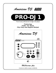
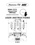
PRO-DJ2
front load professional single CD player
featuring:
Seamless Loop, Fader “Q” Start, BOP Effect,
Flip Flop and Digital Output
© American DJ® AUDIO Los Angeles, CA 90058 USA
IMPORTANT SAFETY ITEMS FOR
U.S.A. & CANADA MODEL ONLY
WARNING:
TO PREVENT FIRE OR SHOCK HAZARD,
DO NOT EXPOSE THIS CD PLAYER TO
WATER OR MOISTURE.
CAUTION:
1. Handle the power supply cord carefully. Do not
damage or deform; it may cause electric shock
or malfunction when used. Hold plug attach
ment when removing from wall outlet. Do not
pull on the cord.
2. To avoid electric shock, do not open the top
cover when the unit is plugged in. If problems
occur with the unit, call your local American DJ
AUDIO dealer.
3. Do not place metal objects or spill liquid inside
the CD player. Electric shock or malfunction
may occur.
Please record and retain the model name and
serial number from your rating label. for future
reference
Model No._________________________
Serial No._________________________
CAUTION
Do not open risk of electric shock
CAUTION: TO REDUCE THE RISK OF ELECTRIC
SHOCK, DO NOT REMOVE THE COVER RACK.
THERE ARE NO USER SERVICEABLE PARTS
INSIDE. REFER SERVICE TO YOUR
AUTHORIZED AMERICAN DJ AUDIO DEALER.
NOTE:
This CD player uses a semiconductor laser.
It is recommended for use in a room at the
following temperature: 41˚F - 95˚F / 5˚C - 35˚C
CAUTION
TO PREVENT ELECTRIC SHOCK DO NOT USE THIS
(POLARIZED) PLUG WITH AN EXTENSION CORD,
RECEPTACLE OR OTHER OUTLET UNLESS THE
BLADES CAN BE CAREFULLY INSERTED TO PREVENT
BLADE EXPOSURE.
CAUTION:
USE OF CONTROLS OR ADJUSTMENTS
OTHER THAN THOSE SPECIFIED HEREIN MAY
RESULT IN HAZARDOUS RADIATION EXPOSURE.
THE COMPACT DISC PLAYER SHOULD NOT BE
ADJUSTED OR REPAIRED BY ANYONE EXCEPT
PROPERLY QUALIFIED SERVICE PERSONNEL.
NOTE:
This unit may cause interference to
radio and television reception.
Line Voltage Selection
(for multiple voltage model only)
• The desired voltage may be set with the
VOLTAGE SELECTOR switch on the rear
panel (using a flat head screw driver).
• Do not force the VOLTAGE SELECTOR
switch as this may cause damage.
• If the VOLTAGE SELECTOR switch does
not move smoothly, please contact a qualified service technician.
The lightning flash with an arrow triangular
symbol is intended to alert the user to the
presence of uninsulated “dangerous voltage” within the products enclosure, and may
be of sufficient magnitude to constitute a
risk of electric shock.
The exclamation point triangular symbol is
intended to alert the user to the presence of
important operating and maintenance (servicing) instructions in the user manual
accompanying the CD player.
American DJ® AUDIO • PRO-DJ2 INSTRUCTIONS MANUAL • PAGE 2
VOLTAGE SELECTOR switch
SAFETY INSTRUCTIONS
I. Read Instructions - All the safety and operating
instructions should be read before the appliance
is operated.
2. Save Instructions - The safety and operating
instructions should be saved for future
reference.
3. Heed Warnings - All warnings on the appliance
and in the operating instructions should be
adhered to.
4. Follow Instructions - All operating and user
instructions should be followed.
5. Water and Moisture - The appliance should not
be used near water - for example, near a bath
tub, washbowl, kitchen sink, laundry tub, in a
wet basement or near a swimming pool, etc.
6. Ventilation - The appliance should be situated
so that its location or position does not interfere
with its proper ventilation. For example, the
appliance should not be situated on a bed, sofa,
rug, or similar surface that may block the
ventilation openings; or, placed in a built-in
installation, such as a bookcase or cabinet that
may impede the flow of air through the
ventilation openings.
7. Heat - The appliance should be situated away
from heat sources such as radiators, heat
registers, stoves, or other appliances (including
amplifiers) that produce heat.
8. Power Sources - The appliance should be
connected to a power supply only of the type
described in the operating instructions or as
marked on the appliance.
9. Grounding or Polarization - Precautions should
be taken so that the grounding or polarization
means of an appliance is not defeated.
10. Power-Cord Protection - Power-supply cords
should be routed so that they are not likely
to be walked on or pinched by items placed
upon or against them, paying particular
attention to cords at plugs, convenience
receptacles, and the point where they exit
from the appliance.
11. Cleaning - The appliance should be cleaned
only as recommended by the manufacturer.
12. Non-use Periods - The power cord of the
appliance should be unplugged from the outlet
when left unused for a long period of time.
13. Object and Liquid Entry - Care should be taken
so that objects do not fall and liquids are not
spilled into the enclosure through openings.
14. Damage Requiring Service - The appliance
should be serviced by qualified service
personnel when:
A. The power-supply cord or the plug has
been damaged.
B. Objects have fallen, or liquid has been
spilled into the appliance.
C. The appliance has been exposed to rain
or water.
D. The appliance does not appear to operate
normally or exhibits a marked change in
performance.
E. The appliance has been dropped, or the
enclosure damaged.
15. Servicing - The user should not attempt to
service the appliance beyond that described in
the operating instructions. All other servicing
should be referred to qualified service
personnel.
American DJ® AUDIO • PRO-DJ2 INSTRUCTIONS MANUAL • PAGE 3
FUNCTIONS AND CONTROLS
PRO DJ 2
Control Layout
20
19
1
18
2
17
3
16
4
5a
5b
15
14
13
6
22
23
24
25
21
7
30
8
9
10
29
11
12
28
31
32
27
38
1.
2.
3.
4.
5a.
5b.
6.
37
36
35
34
33
26
Figure 1
Direct Track Access Buttons (1-10) - These buttons are used to select a starting track. They are also used in
Memory (2) and Recall (3) modes for cue points.
Memory - This button is used to program up to 10 cue points per a CD in to the Direct Track Access
Buttons (1-10) Press the Memory (2) button during play or pause, the memory LED lights up. Use the frame
search to reach the desired cue point, then press a Direct Track Access Buttons (1-10) to memorize that
starting point. Repeat the preceding steps to memorize all 10 starting points, if desired.
RECALL - This button allow you to cue up any of the 10 memory points that have been memorized. Press
RECALL button then any of the 10 number buttons. the player will cue up the selected point if in Pause Mode.
The player will continue to play music if it is the Play Mode.
OPEN/CLOSE - (Disc Tray Open/Close)- Press to load or eject the disc. Each press will open or close the disc
tray on the transport. NOTE: Tray will not open unless the disc has been paused.
IN BUTTON - (CUE “ON THE FLY”) This allows you to set a CUE POINT without stopping the play back. This
button also sets the beginning of a seamless loop.
OUT BUTTON - Used to set the ending point when looping. When the OUT BUTTON is pressed, the player
will play the loop continuously. To exit the loop, press the OUT BUTTON again.
SHUTTLE WHEEL - (OUTER RING) This wheel has 6 forward and 6 reverse speed positions for searching
through songs. The more you turn the wheel in either direction the faster you search through the music.
American DJ® AUDIO • PRO-DJ2 INSTRUCTIONS MANUAL • PAGE 4
FUNCTIONS AND CONTROLS CONT.
7.
8.
9.
10.
11.
12.
13.
14.
15.
16.
17.
18.
19.
20.
21.
22.
23.
24.
25.
26.
27.
JOG WHEEL - (INNER RING) This jog wheel serves two functions depending on the mode you are working in.
a. The jog wheel will act as a slow frame search control when the CD is not playing but either paused or set to
a cue point. To set a new frame cue point, spin the wheel then press PLAY (11) when you have determined the
proper position. Press CUE (9) to return to the “CUE POINT”.
b. It also works as a pitch bend, when you turn clockwise the pitch will rise to 16%, and when you turn
counterclockwise it will fall to -16%. The pitch bend is determined on how fast you turn the wheel.
TRACK BUTTON - This button is used to select a BACK SKIP track to be played.
CUE - Pressing the CUE BUTTON during play provides a return to the position at which play was started. If
PAUSE is used before CUE or a CUE POINT was set, that will become the cue point. Alternately pressing the
PLAY button and the CUE BUTTON allows the CD to be played from the same position any number of times.
The CUE LED will light up from the time the Cue button is pressed until the CD has reset to the position at
which play was started. Steady lighting of this LED indicates the ready condition. The CUE button can be held
down to play a CD. When you release the CUE BUTTON it instantly returns to the CUE POINT. You can also
tap the CUE BUTTON to create a BOP EFFECT (See page 7 sec. g).
TRACK BUTTON - This button is used to select a Forward Skip track to be played.
PLAY/PAUSE BUTTON - Each press of the PLAY/PAUSE BUTTON causes the operation to change from
play to pause or from pause to play.
BOP BUTTON - Pressing the BOP BUTTON will play from the CUE point instantly, when in the play mode.
PITCH SLIDER - The pitch can be changed from (+/- 8%), (+/- 12%) or (+/- 16%). Press the PITCH
BUTTON (20) until the PITCH LED is lit, then move the PITCH SLIDER. The pitch will not be changed if the
PITCH LED is off. Pitch percentage (%) can be changed by holding the PITCH BUTTON (20) and pushing the
plus (+) BUTTON (16) to change the percentage (%) selection.
RELOOP BUTTON - If a SEAMLESS LOOP has been made, but the CD Player is not actively in SEAMLESS
LOOP mode, press the RELOOP BUTTON to reactivate the SEAMLESS LOOP mode. RELOOP will appear
in the LCD DISPLAY (31). To exit loop, press the OUT BUTTON(5b).
LCD DISPLAY - Indicates all the functions, as they are occurring, with the CD. These functions are explained
on page 6. The LCD will flash when in sleep mode - This is not a malfunction.
(+) & (-) PITCH BEND Button - When each of the two CD players is playing a CD, the pitch bend function
allows the positioning of the bass beats to be matched after the pitch of each disc is matched. Either player can
“catch up” or “fall back” to match the other player. The pitch will automatically rise while the (+) BUTTON
(16) is pressed (allowing “catch up”) and return to the original pitch when the button is released. The pitch will
automatically drop while the (-) BUTTON (16) is pressed (allowing “fall back”) and return to the original pitch
when the button is released. By changing the pitch of one disc with respect to the other in this way the beats
can be matched.
SGL/CTN - You can choose between a single track to play or all tracks in order by pressing once or twice.
TIME BUTTON - The TIME BUTTON switches between ELAPSED TIME, REMAINING TIME and TOTAL
REMAINING TIME, the current function will be displayed in LCD DISPLAY (15).
PROGRAM - Depress this button to stop the CD and enter the program mode. Note the word “PROGRAM” is
indicated on the display. Select each track to be programmed with the forward and back SKIP BUTTONS
(5A & 5B). and press the PROGRAM BUTTON between selections. You can program up to 30 tracks. Press
PLAY (11) to start the program. To exit and erase program hold the program button down for more than 2
seconds while the unit is stopped, open the disc tray, or turn off the power.
PITCH - (+/- 8%), (+/-12%), (+/-16%) This button activates the PITCH SLIDER (13). Select percentage of
pitch by holding the PITCH BUTTON. When pitch LED is lit, press down the PITCH BUTTON and tap the
(+) BUTTON (16) until desired pitch percentage (%) is reached. Move the pitch slider to the top or the
bottom position to view the current setting.
DISC TRAY - Press the OPEN/CLOSE BUTTON(4) to open and close the disc tray. Place CDs in the tray.
POWER SWITCH (Main power On/Off) - I don’t really have to describe this one, do I?
CONTROL JACK - Use this jack to connect a mini plug from the Pro DJ2 player to a compatible American DJ
“Q Deck” mixer to activate the “Fader Q Start” function. (See “Q” Start Control on page 7 sec. g)
DIGITAL OUTPUT JACK - Use this jack to connect the digital output signal of Pro DJ2 played to a Mixer,
DAT, or any piece of equipment that accepts a digital in signal.
AUDIO OUT - Left and Right audio output. Connect RCA cables from AUDIO OUT to a mixer input.
VOLTAGE SELECTOR - Select which voltage desired: 115V or 230V. Always disconnect the power plug before
changing the voltage.
POWER CONNECTOR/FUSE - IEC Power Connector with built-in fuse holder. Always replace with the same
type fuse.
American DJ® AUDIO • PRO-DJ2 INSTRUCTIONS MANUAL • PAGE 5
FUNCTIONS AND CONTROLS CONT.
28.
SINGLE INDICATOR - This indicates that the player is in single play mode. Playback will stop and cue at the
beginning of the next track.
29.
PROGRAM INDICATOR - This lights when in program is selected or program play is selected.
30.
PLAY INDICATOR ( ) - The PLAY indicators light during playback.
31.
LOOP, RELOOP INDICATORS - Displays when LOOP is engaged. LOOP flashes in LCD DISPLAY (8) when
playing loop.
32.
PITCH INDICATOR- Lights when PITCH (20) is engaged.
33.
PITCH DISPLAY - Displays the percentage of pitch adjustment, according to the PITCH FADER (13).
34-36. MINUTE, SECOND, & FRAME INDICATORS - Displays the running time of the current track (Elapsed,
Total, Remaining).
37.
TRACK INDICATOR - Displays which TRACK is being played.
38.
PAUSE INDICATOR ( ) - The PAUSE indicators will light during pause or cue mode.
PREPARATIONS
CAUTION:
1. Checking the Contents
• Be sure to use the supplied control cables. Using other
Check that the carton contains the following items:
types of cable may result in unit damage.
1) Main unit.
• Be sure the power is off when connecting the control
2) Operating instructions (this booklet).
cables, otherwise the units may not work properly.
3) A pair of RCA cables.
2. Installing the Units
Mount the units onto your console or place on a flat surface
3. Connections
1) Turn off the POWER switch.
2) Connect the RCA cables from your PRO DJ2 to the inputs on your mixer.
3) Connect a cable via the mini jack connector on the PRO-DJ2 to a mini jack connection (A or B ) on a compatible
American DJ “Fader Q Start” mixer. (This will enable the Fader “Q” Start function - See “Q” start control pg.7)
CAUTION:
• The player will work normally when the main unit is
mounted with the front panel within 15 degrees of
the vertical plane. If the unit is tilted excessively,
discs may not be loaded or unloaded properly.
(Figure 2a)
CAUTION:
• The LCD is designed to be clearly visible within the
angles shown in Figure 2b. Mount the control unit so
that the visual angle is within this range.
10
15
Fig. 2a
Fig. 2b
GENERAL NOTES ON USE
•
•
•
•
•
•
•
•
•
•
Avoid operating in high temperatures.
Allow for sufficient heat dispersion when installed on a rack or case.
Handle the power cord carefully.
Hold the plug from the ends when unplugging the cord. Never pull the plug out from the cable.
Keep the set free from moisture, water, and dust.
Unplug main power when not using the unit for long periods of time.
Do not obstruct the ventilation holes. (For units with ventilation holes.)
Do not let foreign objects enter into the unit.
Do not let insecticides, benzene, and thinner come in contact with the unit.
Never disassemble or modify the unit in any way.
American DJ® AUDIO • PRO-DJ2 INSTRUCTIONS MANUAL • PAGE 6
50
MAIN FEATURES
(1)
(2)
(3)
(4)
(5)
(6)
(7)
(8)
(9)
(10)
(11)
(12)
(a)
(b)
(c)
(e)
8 times over sampling 1 bit D/A converter
Auto cue
1/75th second frame search
Realtime cue (“Cue on the Fly”)
6 different speed scan
Pitch display
10 number buttons for direct track access
30 programmable tracks
10 cue points can be memorized
Digital output RCA coaxial
Fader “Q” Start Function, controls play and stop function via
a compatible ADJ “Q Deck” mixer. (a)
Large bright LCD Screen can be viewed from
NOTE: The second and third ways of creating a BOP EFFECT are
superior methods because there will be no interruption of music.
(g)
wide angles.
60 seconds transport protection (b)
Seamless Loop
CD Recordable (CDR) compatible
Flip-Flop, Relay Playback when used in pairs (c)
+/- 8%, 12%, 16% selectable on Pitch Slider
Sleep Mode after 15 min. (d)
Bop Effect (e)
Jog Wheel Pitch Bend +/- 16%
Memory Backup, Default to last setting (f)
Instant Start
“Q” Start Control (g)
Light weight and compact design.
SLEEP MODE PROTECTION: After 15 minutes in PAUSE or CUE Mode the CD drive mechanism will automatically go
in to sleep mode. This function shuts down the laser pick-up diode extending the life of the unit. During sleep mode the LCD
screen will flash repeatedly indicating sleep mode is activated - This is not a malfunction, to restart the drive simply press
the Cue or Play/Pause Buttons
60 SECOND TRANSPORT PROTECTION: Will automatically close transport if left open for more than 60
seconds to prevent someone from walking by and breaking the transport.
FLIP-FLOP: On the rear of the PRO DJ2 there is a control input jack, use a standard stereo mini plug to plug in one PRO
DJ2 to another, via the control jacks. Set both of the CD players to single play mode. Play Disc 1, Disc 2 will immediately
begin to play when the track ends on disk 1. Disc 1 will return to cue mode and will begin to play at the end of disc 2 track.
This function will continue until the jacks are disconnected but may be overriden at any time through manual operation.
BOP EFFECT: A Bop Effect is a stutter, creating a sound similar to a CD skipping. The Bop Effect can be created in 3 ways.
(1) By Rapidly Pressing the CUE BUTTON (9)
a. While in play mode, rapidly press the CUE BUTTON (9)
in sync with the music (figure 2).
(2) By Tapping the DIRECT TRACK ACCESS BUTTONS (1)
a. While in play mode, press the IN CUE BUTTON (5a)
(see figure 4).
b. Press the MEMORY BUTTON (2) (figure 6) to set a CUE
POINT in memory. MEMORY LED will light (figure 7).
c. Press desired DIRECT TRACK ACCESS BUTTONS (1)
(see figure 5).
d. Press RECALL BUTTON (3) (see figure 7).
e. Once RECALL LED lights, rapidly press the DIRECT
TRACK ACCESS BUTTON (1) previously selected in
step c.(figure 5).
(3) By Tapping the BOP BUTTON (12).
a. Press the IN BUTTON (5a) to set a cue point.
b. Turn the RECALL FUNCTION ON (3).
c. Press the BOP BUTTON (12), while in play mode to
return to the cue point instantly without music interruption.
d. Rapidly press the BOP BUTTON (12) in sync with the
music to create different effects.
(f)
(13)
(14)
(15)
(16)
(17)
(18)
(19)
(20)
(21)
(22)
(23)
(24)
fig.2
fig.5
fig.6
fig.3
fig.7
fig.4
Memory Backup: This will automatically save your last setting (repeat, SGL, CTN) even if you unplug AC- current. It will
also hold your cue points in memory if you accidentally open transport or shut off power. Memory cues are erased automatically when a new CD is inserted in to the drive, or by holding down the MEMORY BUTTON (2) down for 3 - 4 seconds.
“Q” Start Control: This feature is used with American DJ “Q-Series” mixers featuring Fader Start. Connect the standard
mini plugs supplied, from CD1 output on CD player to the “A” player control input on the rear of mixer. Then connect the
other mini plug from CD 2 output on CD player to the “B” player control input on the rear of mixer. By moving the mixer
fader from left to right you can start and pause Disc1 and Disc 2 respectively. In other words, when the cross-fader of the
mixer is to the left, and you move it 20% to the right, Disc 2 will begin to play. When the cross-fader is to the right, and you
move it 20% to the left, Disc 1 will begin to play. You can create great effects similar to scratching with this feature. After
storing cue points on each side of the CD player, different songs or samples can quickly be recalled by moving the mixer
cross-fader back and forth. New cue points can be easily selected on the CD player (1,19,20). “Q” Start control is easy to
use and mastering this feature will help you create amazing effects with your music.
American DJ® AUDIO • PRO-DJ2 INSTRUCTIONS MANUAL • PAGE 7
BASIC OPERATIONS
1. OPENING AND CLOSING THE DISC TRAY AND LOADING DISCS
• This operation only works when the power is on.
• Press the OPEN/CLOSE BUTTON (4) to open or close the disc tray, or, Press PLAY BUTTON (11) to close
the tray automatically when it is open.
•
If the tray is not closed after 60 seconds it will close automatically and go into pause mode.
•
The disc trays cannot be opened during playback to prevent playback from being interrupted if the OPEN/
CLOSE BUTTON (4) is pressed accidentally. Stop playback, then press the OPEN/CLOSE BUTTON (4)
2. LOADING DISCS
•
Hold the disc by the edges and place it in the disc tray. Do not touch the signal surface (the glossy side).
•
When using 5 inch/12 cm discs, place the disc in the outer tray guides and when using 3 inch/8 cm discs, place
them securely in the inner guides.
CAUTION:
•
DO NOT place any foreign objects in the disc tray, and do not place more than one disc in the disc tray at a time.
Doing so may result in malfunction.
•
DO NOT push the disc tray in manually when the power is off, as this may result in malfunction and damage the
player.
3. SELECTING TRACKS
•
Select desired track using NUMBER BUTTON (1) or
•
Press the TRACK BUTTONS (5A/5B) once to move to one higher or lower track or
•
Hold the TRACK BUTTONS (5A/5B) in to change tracks continuously at a higher speed.
•
When a new track is selected during playback, playback begins as soon as the search operation is completed.
4. STARTING PLAYBACK
•
Press the PLAY/PAUSE BUTTON (11) during the pause or cue to start playback.
•
The PLAY INDICATOR (30) lights when playback starts.
•
The point at which playback starts is automatically stored in the memory as the cue point. The pickup then
returns to the cue point (the point at which playback started) when the CUE BUTTON (9) is pressed.
5. STOPPING PLAYBACK
•
There are two ways to stop playback.
1) Press the PLAY/PAUSE BUTTON (11) during playback to pause at that point.
2) Press the CUE BUTTON (9) during playback to return to the position at which playback started.
6. PAUSING
•
Press the PLAY/PAUSE BUTTON (11) to switch between play and pause.
•
The PAUSE INDICATOR (38) lights when the pause mode is set.
7. CUEING
•
“Cueing” is the action of preparing for playback. When the CUE BUTTON (9) is pressed, playback returns to
the cue point and enters pause mode. When the PLAY/PAUSE BUTTON (11) is pressed during the cue mode,
playback starts.
•
CUE POINT SETTING:
A Playback starts from pause or skip to a new track during play or pause. The beginning play point will be set to
the cue point.
B Or, Press the IN BUTTON (5a) button during playback to set the new cue point.
C Or, Save up to 10 CUE points by pressing MEMORY, then set desired Cue, then press any of DIRECT TRACK
ACCESS BUTTONS (1). You can also set any of the 10 Cue points by pressing MEMORY then any of the
DIRECT TRACK ACCESS BUTTONS (1) above the LED screen.
•
To return to a CUE POINT press CUE BUTTON (9). This will return to point A or B above. The player has
completed the cue or pause operation and is waiting for the play start command. When the PLAY/PAUSE
BUTTON (11) is pressed, playback starts.
•
To Return to any of the 10 Cue points, press RECALL (3), then the desired DIRECT TRACK ACCESS BUTTONS (1). The player has completed the cue or pause operation and is waiting for the play start command.
When the PLAY/PAUSE BUTTON (11) is pressed, playback starts.
•
To recall cues, if the recall LED is lit you can press the last number button cue stored and create a BOP
EFFECT. The last cue that was stored or recalled will flash in the LED screen to let you know It was last
cued up.
NOTE: When play starts via pause or track skipping or scanning, the CUE POINT will change to the start point automatically.
American DJ® AUDIO • PRO-DJ2 INSTRUCTIONS MANUAL • PAGE 8
BASIC OPERATIONS (CONT.)
8. AUTO CUE
• When disk is loaded, the cue point is set to the first source of music. If track is changed before pressing play, the
CUE POINT is changed to the new starting point. If you pause during playback this also sets the new CUE
POINT.
9. FRAME SEARCH
• This is done by first pausing then using the jog wheel to set the starting point. (When you use the jog wheel the
monitor function allows you to hear what is playing. Once you have set starting point press PLAY then CUE to
again mute output.)
10. SCANNING (FAST FORWARD / FAST REVERSE)
• To do this rotate Shuttle wheel forward or reverse. You can scan or reverse in 6 different speeds depending on how
much you rotate the wheel.
11. SEAMLESS LOOP PLAY
• You can create a seamless loop between two points continuously.
(1) Press PLAY/PAUSE BUTTON (11) so a CD is playing. The PLAY/PAUSE BUTTON (11) LED lights
(figure 10).
(2) Press IN BUTTON (9). This sets the starting point of the SEAMLESS LOOP. The IN BUTTON LED will light
(figure 11).
(3) Press OUT BUTTON (5b) to set desired ending point of the SEAMLESS LOOP. You will know you are in
SEAMLESS LOOP mode because IN BUTTON (5a) and OUT BUTTON (5b) LEDs will light and flash.
LOOP INDICATOR (31) in LCD DISPLAY (15) will also flash (see figure 14). Sound will continue with no
interruption (SEAMLESS LOOP).
(4) To exit the SEAMLESS LOOP, press the OUT BUTTON (5b). LEDs will stay on but not flash. Music will
resume normal play (figure 13).
(5) To replay loop, press the RELOOP BUTTON (23). IN BUTTON (5a) and OUT BUTTON (5b) LEDs and
fig. 10
fig. 11
fig. 12
fig. 13
fig. 14
LOOP INDICATOR (31) in LCD DISPLAY (15) will all begin flashing again (figure 14).
12. EDITING A LOOP: NOTE: YOU CAN ONLY EDIT THE ENDING PART OF THE LOOP.
(1) You must be in SEAMLESS LOOP mode. If a SEAMLESS LOOP has not been created, follow instructions in
step 11 for creating a SEAMLESS LOOP. If a SEAMLESS LOOP has already been created and you wish to
edit it, press RELOOP BUTTON (14) to reenter the SEAMLESS LOOP mode (figure 14).
(2) Next, press OUT BUTTON (5b) to return to normal play (figure 13). This disengages the SEAMLESS LOOP
mode.
(3) Press OUT BUTTON (5b) again for new desired ending point of the loop (figure 13).
FOR SHORTER LOOP: press OUT BUTTON (5b) quickly.
FOR LONGER LOOP: Wait until the song plays several frames, them press OUT BUTTON (5b).
13. TIME DISPLAY
• During normal play, each time you press the TIME BUTTON (18), the display changes to give you the following
information (see figure 1, LCD screen).
(1) ELAPSED playing time
(2) REMAINing time of a track. If the current track number is over 34, “...................” is displayed.
(3) TOTAL remaining time of the disc.
14. PITCH BENDING
• The speed increases or decreases respectively when the PITCH BEND (+) BUTTON (9) or PITCH BEND (-)
BUTTON (9) is pressed. The extent to which the speed changes is proportionate to the amount of time the
button is pressed. For example, if the PITCH BEND (+) BUTTON (16) is held in continuously, the speed
increases continuously.
• The pitch can be changed from +/- 8%, +/- 12%, or +/- 16% range. See changing PITCH PERCENTAGE (15).
• The jog wheel will temporarily bend the pitch of the music if the song is already playing. Rotate the wheel
clock-wise to speed up or counterclockwise to slow down. The speed that you rotate the inner JOG WHEEL
determines the percentage (%) of the PITCH BEND.
American DJ® AUDIO •PPRO-DJ2 INSTRUCTIONS MANUAL • PAGE 9
BASIC OPERATIONS (CONT.)
16. PROGRAM PLAY
(1) Press the PROGRAM BUTTON (19) to make the unit enter the program mode in stop position. The
PROGRAM INDICATOR (29)LED above the PROGRAM BUTTON (19) will light as well as the
PROGRAM INDICATOR (29) on the LCD DISPLAY (15).
(2) Select a Track by using the DIRECT TRACK ACCESS BUTTONS (1) , press PROGRAM BUTTON (19)
again.
(3) Repeat this up to 30 times (ie. up to 30 tracks can be programmed). If you keep pressing the PROGRAM
BUTTON (19) the LCD DISPLAY (15)will display the tracks that have been programmed.
(4) Press the PLAY BUTTON (11) to begin playing programmed tracks.
(5) To cancel the program function press and hold PROGRAM BUTTON (19) for more than 2 seconds.
BEFORE SWITCHING OFF THE POWER
• When you have finished using the CD player, and before switching off the power, be sure that the disc holder has
been closed with the OPEN/CLOSE BUTTON (4).
• TRAY PROTECTION: If tray is not closed after 60 seconds, it will close automatically and pause.
• Do Not switch off the power when the disc holder is open.
• Switch off the power only after the disc tray has been closed with the OPEN/CLOSE BUTTON (4).
CAUTION: DO NOT forcibly close the disc holder when the power is off!
COMPACT DISCS
1. PRECAUTIONS ON HANDLING COMPACT DISCS
• Keep fingerprints, oil and dust off the surface of the disc. If the disc is dirty, wipe it off with a soft dry cloth.
• Do not use benzene, thinner, water, record spray, electrostatic-proof chemicals, or silicone-treated cloths to clean
discs.
• Always handle discs carefully to prevent damaging the surface; in particular when removing a disc from its ends
• Do not bend the disc.
• Do not apply heat.
• Do not enlarge the hole in the center of the disc.
• Do not write on the label (printed side) with a hard tipped instrument such as a pencil or ball point pen.
• Condensation will form if a disc is brought into a warm area from a colder one, such as outdoors in winter. Do
not
attempt to dry the disc with a hair dryer, etc.
2. PRECAUTION ON STORAGE
• After playing a disc, always unload it from player.
• Always store the compact disc in the jewel case, protecting from dirt or damage.
• Do not place discs in the following areas:
a) Areas exposed to direct sunlight for a considerable time.
b) Areas subject to accumulation of dust or high humidity.
c) Areas affected by heat from indoor heaters, etc.
CDS LEFT IN PLAYER
• If a CD is left in the player and the remote has been disconnected, plug power cable in, turn on power and take
out CD.
American DJ® AUDIO • PRO-DJ2 INSTRUCTIONS MANUAL • PAGE 10
SPECIFICATIONS
GENERAL:
Type:
Disc type:
Dimensions:
Installation:
Weight:
Power supply:
Power consumption:
Environmental conditions:
Disc Loading:
Display:
Twin mechanism compact disc player with wired controller.
Standard compact discs (5 in / 12cm and 3in/8cm discs)
Player unit:
19"(W) x 3 15/32” (H) x 9 55/64” (D)
Table-top mount
6 lbs. / 2.4 kgs
110~120v/220~240v AC, 50/60Hz
25W
Operational temperature: 5 to 35˚C (41 to 95˚F)
Operational humidity: 25 to 85% (no condensation)
Storage temperature: -20 to 60˚C (4 to 140˚F)
Front loading
1 digital LCD display, 8 LED indicator
AUDIO SECTION:
Quantization:
16 bit linear per channel
Sampling rate:
44.1 kHz at normal pitch
Over sampling rate:
8 times 1 BIT D/A converter
D/A conversion
16 bit
Frequency response:
+/- 1 dB 20 Hz to 20,000 KHz
T.H.D.:*
0.02%
Signal to noise ratio:*
88 dB
Channel separation:*
80 dB
Output level:
2.0V +/- 1dB
Load impedance:
47k ohm or more
* with 20KHz low pass filter
TECHNICAL FEATURES:
Variable pitch; +/-8%, +/-12% or +/-16%; accurate within +/- 0.1%
Search accuracy; 1/75 sec. (1 subcode frame)
Seamless Loop (uninterrupted loop playback).
Digital output RCA coaxial
Auto protection (after 15 minutes with no operating in pause mode, the laser diode will be turned off).
Specifications and design are subject to change without notice for purpose of improvement.
American DJ® AUDIO World Headquarters:
4295 Charter Street
Los Angeles, CA 90058 USA
Tel: 323-582-2650
Fax: 323-582-2610
Web: www.americandj.com
E-mail: [email protected]
revised 8/99
American DJ® AUDIO • PPRO-DJ2 INSTRUCTIONS MANUAL • PAGE 11
Q-2221 “Q-DECK”
USER INSTRUCTIONS
djs wanted.
Q-2221
“Q-DECK”
Featuring
Fader “Q” Start
Main Features
• 2 phono, 2 line, 2 auxiliaries, & 1 microphone input
• Hamster Switch for changing cross fader position
• 100% cut buttons for treble, mid and bass of each channel
• Fader "Q" Start w/ On/Off switch (for use with the American DJ CD Players with Fader "Q" Start)
• -30dB Rotary Kills for treble, bass & mids • Changeable transformer switch to up/down or left/right
• Equipped with high quality Alps Feather Fader™ (FF-4) Crossfader(replaceable/made in Japan)
• Fader Curve Switch - changes from a normal curve to a quick curve (for crabbing)
• Separate gain control for each channel • Bass, mid & treble on microphone
• High output to headphones • 2 separate headphone inputs
• Soft-touch rubber knobs for better control
• Super clean signal to noise ratio
professional products designed for the working dj.
© American DJ® AUDIO Los Angeles, CA 90058 USA
Specifications subject to change without notice.
Q-2221 “Q-DECK” User Instructions page 2
Index
• Safety Instructions..................................................................................p.3
• Operating Determinations.......................................................................p.4
• Connections.............................................................................................p.4
• Functions (Front Panel)........................................................................p.5-6
• Inputs & Outputs (Rear Panel)...........................................................p.6-7
• Replacing the Crossfader.......................................................................p.7
• Changing the Transformer Switch...........................................................p.7
• Technical Specifications.........................................................................p.7
• Warranty & Service..................................................................................p.8
Thank you for purchasing this American DJ® product. The Q-2221 Is ready to be
used, there Is no assembly required. Please read the following Instructions before
installing or using your new unit. The Q-2221 has a 2 year limited warranty!
CAUTION! - Keep this device away from rain and moisture!
Safety Instructions
Always plug in the power last. Make sure that the Power switch is set to the OFF position before connecting other
devices to the mixer.
Keep away from heaters and other heating sources!
If the device has been exposed to drastic temperature fluctuation (e.g. after transportation), do not switch on the mixer
immediately. The arising condensation of water might damage your device. Leave the device switched off until it has
reached room temperature.
Never put any liquids on the mixer or close to it. Should any liquid enter the device, disconnect from main power
immediately. Have the device checked by a qualified service technician before operating again. Any damage caused
by liquid entering the device is not subject to warranty!
Never let the AC cord come in contact with other cables! Handle the AC cord and all AC connections with particular care.
Make sure that the available voltage is not higher than stated on the AC voltage selector (29).
Before the device is switched on, all fader and volume controls should be set to 0 or minimum position.
Damages caused by manual modifications to the device or unauthorized operation by unqualified persons are not
subject to warranty.
There are no user serviceable parts inside the mixer. For maintenance and/or service, contact an authorized American
DJ® dealer.
Q-2221 “Q-DECK” User Instructions page 3
Operating Determinations
When installing this mixer, please make sure that the device is not exposed to extreme heat, moisture or dust! There
should not be any cables lying around. Doing so endangers you as well as others. Do not operate the mixer in extremely
hot (more than 30° / 100°F) or extremely cold (less than 5°C / 40°F) surroundings. Keep away from direct sunlight and
heaters.
Operate the mixer only after becoming familiar with its functions. Do not permit operation by persons not qualified for
operating the mixer. Most damages are the result of unprofessional operation!
Never use spray cleaners to clean the faders! Never use solvents or abrasive detergents to clean the mixer! It is recommended that you use a soft damp cloth. Please consider that unauthorized modifications on the device are forbidden
due to safety reasons!
Connections (Refer to diagrams on pages 5 & 6)
• Make sure that the power switch (1) is set to OFF. Before connecting other devices to the mixer, all units have to be
switched off and the Master Control (17) set to min.
• Make sure that the available voltage is not higher than stated on the voltage selector (29) before connecting to power.
• In order to obtain the highest sound quality, only use high quality American DJ®, Ameri-Cable ™ cables for connecting
devices. Make sure that the cables are properly fixed.
• Connect your amplifier to the MASTER OUT jacks (25). Make sure that the channels are set properly.
• For recording, connect your tape recorder or cassette deck to the OUTPUT REC jacks (24). The REC OUT level will
not be influenced by the Master Control (17).
• Connect your microphone to the Microphone Input (26) on the rear panel (see diagram on page 4).
• The Q-2221 features one microphone input. The 1/4 inch (6.3mm) MIC JACK (26) on the rear panel. You can adjust
the microphone volume output by turning the DJ MIC LEVEL (19) . DJ MIC TREBLE & BASS may be controlled by the
BASS & TREBLE KNOBS (19) below the DJ MIC KNOB.
• You can connect 2 turntables using the LEFT & RIGHT RCA PHONO 1 (21) and PHONO 2 jacks (22) on the rear
panel. You can only control the turntables signal after you have switched the PHONO /AUX SELECTOR SWITCH (23)
on the rear panel to PHONO, plus you must change the PHONO/AUX/LINE SWITCH (5a, 5b) on the front panel to
PHONO/AUX. The signal is then controlled via the CH-1 and CH-2 faders (6).
• Connect your tape recorder, tuner, sound effects, CD player, and cassette decks etc. to the LEFT & RIGHT RCA LINE
signals (21, 22) to the AMP OUT jacks (21, 22) on the rear panel. The signal is then controlled via the CH-1 and CH-2
faders (6) when the PHONO/AUX/LINE SWITCH on the front panel (5a, 5b) to LINE . CD players, cassette decks etc.
may also be connected to the LEFT & RIGHT RCA PHONO/AUX jacks (17, 18) on the rear of the unit. You can only
control this signal after you have switched the PHONO / AUX SELECTOR SWITCH (23) on the rear panel to AUX, plus
you must change the PHONO/AUX/LINE SWITCH (5a, 5b) on the front panel to PHONO/AUX. The signal is then
controlled via the CH-1 and CH-2 faders (6).
Q-2221 “Q-DECK” User Instructions page 4
Functions (Front Panel)
4
13
2
3
1
11
11
17
19
15
14
16
8
5a
5b
18
7
6
10
9
12
(1) POWER SWITCH - Red LED will light when power is ON.
(2) MASTER LEVEL - Dual LED's show the level of the left and right master output.
(3) GAIN CONTROL - Used to set the level of the input signal for its designated channel.
(4) BASS/MID/TREBLE CONTROL - Used to increase or decrease the LOW's, MID’s, and HI’s of the input signal.
The Q-2221 features "Rotary Kills" with -30dB to +20db input control.
(5a) CHANNEL 1 TRANSFORMER SWITCH (CHANGEABLE) - Used to select the input to be sent to channel 1.
TRANSFORMER SWITCH may be used up/down or left/right. To change the switch, see diagram on page 7.
(5b) CHANNEL 2 TRANSFORMER SWITCH. (CHANGEABLE) - Used to select the input to be sent to channel 2.
TRANSFORMER SWITCH may be used up/down or left/right. To change the switch, see diagram on page 7.
(6) CHANNEL FADER - Used to adjust the output level of each channel.
(7) FADER CURVE SWITCH - Changes Feather Fader™ Crossfader from a NORMAL CURVE to a QUICK CURVE
(used for crabbing).
(8) PFL/CUE BUTTONS - Use the PFL (Pre-Fader Levels)/CUE button to engage the input level of each channel.
(9) FEATHER FADER™ CROSSFADER - Mixes the signals of channel 1 and channel 2. When the crossfader is set
in the center position, both channels can be heard at once.
Q-2221 “Q-DECK” User Instructions page 5
Functions (Front Panel) Cont.
(10) HAMSTER SWITCH - Changes the position of the Feather Fader™ Crossfader (9) (for crabbing).
Channel 1 changes to the right side of the fader (mixing from right to left), and Channel 2 changes to the left side
of the fader (mixing from left to right).
(11) CUT BUTTONS - CUT music 100% on TREBLE, MID or BASS (4) for CHANNEL 1 and CHANNEL 2. When the
Cut Button is pushed the yellow LED will light up indicating a CUT of the Treble, Mid or Bass. Push the button again to
disengage CUT.
(12) ON/OFF “Q” START- Start and stop the CD Player with the slide of the fader. The ON/OFF “Q” START (12 ) switch
activates this FADER “Q” START feature. When in the ON position, the FADER “Q” START allows the fader to return
automatically to preset digital CUE POINTS on your American DJ CD Player* (* also featuring FADER “Q” START). For
example, each time you slide the crossfader to far left the CD Player will be triggered to play the song from the beginning of the preset CUE POINT. Refer to your American DJ CD Player User Manual for setting CUE POINTS. Turn the
ON/OFF SWITCH (12) to the OFF position to disengaged “Q” Start function and resume to a normal fader.
(13) MASTER L/R / PFL CH1/CH2 BUTTON - When the Master L/R is LED is lit the master level (2) shows the master
output that shows the left and right channels master output levels. Push the button again to select PFL CH1/CH2 and
the LED will be lit for that selection. This will make the Master Level (2) show the Pre-Fader Levels (PFL) of Channel 1
and Channel 2.
(14) TALKOVER BUTTON - Press the talkover button when you want to use the microphone. When the button is
pressed, all signals except the microphone level are decreased by 15dB. In the OFF position, all signals return to their
original level. When talkover is ON, the red L.E.D. is lit.
(15) CUE MIXING CONTROL - Selects the channel for monitoring. The monitor signal comes from the Prefader. This
means it will not be affected by the channel faders. You can monitor each channel individually. Connect your headphones to the HEADPHONES jack (18). Turn the CUE MIXING CONTROL (15) to CUE and select the desired channels
with the PFL switches (8). When you turn the CUE MIXING CONTROL to PGM (PFL switches without function), you can
cue the output signal of the mixer. If the CUE MIXING CONTROL is set to the center position, you can cue both the
channel signal you selected and the output signal. With the CUE LEVEL control (16), you can adjust the phones volume
without changing the output signal.
(16) CUE LEVEL CONTROL - Adjusts the headphone output level.
(17) MASTER CONTROL - Adjusts the level of the master output.
(18) HEADPHONES JACKS - Use this jack to connect the headphones. Headphones from 8 Ohms to 600 Ohms can be
used. 16 Ohms is recommended. 2 separate headphone inputs are conveniently located on the face panel and bottom
front panel.
30
31
23
Inputs and Outputs
(Rear Panel)
GND
LIGHT
CONTROL
AC VOLTAGE
SELECTOR
B
20
MIC
A
AUX 2
PHONO 3
AUX 1
PHONO 1
PLAYER CONTROL
AC INPUT 115/230V
FUSE 0.5A, F, 250V
GND
115
L
R
MASTER
REC
LINE 2
OUTPUT
29
28
27
20
26
25
Q-2221 “Q-DECK” User Instructions page 6
PHONO 2
AUX 2
CH-2
24
22
LINE 1
PHONO 1
AUX 1
CH-1
21
Inputs and Outputs Rear Panel) Cont.
(19) DJ MICROPHONE LEVEL / DJ MIC TREBLE CONTROL / DJ MIC BASS CONTROL - The DJ MIC LEVEL
CONTROL adjusts the microphone volume output level. The DJ MIC TREBLE CONTROL and DJ MIC BASS CONTROL
under the DJ MICROPHONE are used to adjust treble and bass of the DJ MICROPHONE.
(20) GND (GROUND TERMINALS) - Connect the ground lead of the turntables with this terminal. This helps to reduce
humming and popping noises. There are two convenient ground terminals located on the rear of the mixer.
(21), (22) LINE / PHONO / AUX INPUT JACKS - Input jack for CH-1, and CH-2. Connect turntables equipped with MM
pickup cartridge to PHONO inputs. CD players or Tape Decks should be connected to LINE input. Line level musical
instruments with stereo outputs such as Rhythm Machines or Samplers should also be connected to LINE inputs.
CHANNEL 1 (21) features left and right RCA inputs for LINE 1 and PHONO 1 / AUX 1. CHANNEL 2 (22) features left
and right RCA inputs for LINE 2 and PHONO 2 / AUX 2. Other inputs (ie. CD players) may also be used in the
PHONO/AUX RCA jacks(21, 22) when the PHONO/AUX SELECTOR SWITCH (23) is set to AUX.
(23) PHONO / AUX SELECTOR SWITCH - Changes phono to an extra line; allows the DJ to use a CD player or other
input device in the same line as the phono line. When using a turntable select PHONO, and when using other input
devices select AUX. PHONO/AUX lines can be used with LINES 1 and 2. The PHONO /AUX SELECTOR SWITCH
gives the DJ the possibilities of 4 inputs lines (ie. 4 lines CD, tape etc.; or 2 lines CD, tape etc. and 2 phono lines).
(24) REC OUT - Connect to your record unit. The REC OUT level is not influenced by the master control (17).
(25) MASTER OUT - Parallel output of P.A. output. Connect with the input of a power amplifier.
(26) MIC JACK - Connect your microphone with 1/4 inch (6.3mm) jack plug here. The signals may be controlled by
the DJ MIC CONTROL KNOB (19). BASS & TREBLE can be adjusted by the DJ MIC BASS CONTROL KNOB (19) and
the DJ MIC TREBLE CONTROL KNOB (19).
(27) FUSE - Fuse holder. Only replace the fuse when the device is disconnected from main power supply. Only replace
with fuses of the same power and rating.
(28) AC CONNECTION - Standard IEC plug with detachable AC power cord.
(29) AC VOLTAGE SELECTOR - Select between 115V/50Hz or 230V/60Hz. Make sure that the selector is set to the
proper voltage you are using.
(30) PLAYER CONTROL - Input mini plugs from CD player controller into these jacks, input CD 1 into jack A and CD 2
into jack B.
(31) LIGHT CONTROL - Buffered audio output for light controllers that can use external input. Great for Touch Panels
and Chase Controllers.
Replacing the Crossfader
• Disconnect from main power supply
• Remove the fader knob.
• Remove the two outer screws.
• Take the fader out and unplug the connection cables.
• Connect the new fader and replace back into mixer.
➔
Changing the Transformer Switch
•
•
•
•
Disconnect from main power supply.
Unscrew 2 larger Phillips screws (see arrow on diagram at the right).
Move switch to desired position.
Reinstall screws.
➔
Q-2221 “Q-DECK” User Instructions page 7
Technical Specifications - model Q-2221
Inputs:
Line: 75mV, 3k Ohm • Microphone: 2.5mV, 600 Ohm • Phono: 1.5mV, 47k Ohm
Output: Line: 25V, peak to peak • Headphones: 5W @ 47 Ohm • Distortion: <0.03%
Signal-To-Noise Ratios:
Line: Better than 85dB • Microphone: Better than 78dB • Phono: Better than 80dB
Frequency Response:
Line: 20Hz - 15KHz, ± 0.5dB • Microphone: 20Hz - 20KHz, ± 0.5dB
ChanneI EQ:
Bass / Mid /Treble: -30dB - +20dB
Talkover Attenuation: - 15dB
Microphone EQ: Bass: -30dB/+12dB @ 100Hz • Treble: -30dB/+12dB @ 1OkHz
Headphone impedance: 16 Ohms
Power supply: AC 115/230V, 50/60Hz switchable
Power Consumption: 5W typical, 7W w/ full headphone output
Dimensions: 12.5" W x 10.25" D x 4" H / 252 x 305 x 102 mm
Weight: 8 lbs. / 3.5 kg
American DJ® AUDIO
4295 Charter Street
Los Angeles, CA 90058 USA
www.americandj.com
Warranty & Service
The Q-2221 has a 2-year limited warranty. Mail in warranty card as soon as possible.
For Service, contact your local American DJ® Dealer.
© American DJ® AUDIO Los Angeles, CA 90058 USA
Specifications subject to change without notice.
Q-2221 “Q-DECK” User Instructions page 8