1
MAXDATA SR1202 Quick Start Guide
European Regulations
This equipment complies with European Regulations EN55022 Class A (Emissions): Limits
and Methods of Measurement of Radio Disturbance Characteristics of Information Technology
Equipments: EN55024 (Immunity) and EN60950 (Safety compliance).
1
Note: The SR1202 supports most of the widely used operating systems, however, deployment on
Microsoft Windows* requires the .inf driver file which is found on the CD.
1
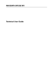
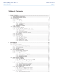
Attach left and right chassis slides to the enclosure sides using 8 M3 x 4 buttonhead screws.
(See Figure 2).
* Windows Servers - Insert the Software and Manuals Disc and install the .inf driver file.
2
Assemble the left and right chassis latches using the special chassis latch screws. Ensure the
latch is orientated as shown in Figure 2, with the spring arm located against its stop. On the
right hand this is at the top, on the left at the bottom.
The Accessory Box contains the AC power cable(s), a serial communication cable, and the Software
and Manuals Disc.
Safety
All plug-in modules are part of the fire enclosure and must only be removed when a replacement
can be immediately added. The system must not be run without all modules in place.
The Accessory Box Insert contains the adjustable rail slides and hardware parts to mount the
enclosure.
3
B
Simplex: Dual Host (Single HBAs)
C
Duplex: Single Host (Dual HBAs)
D
Duplex: Single Switch
E
Connecting Multiple Enclosures
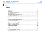
Figure 3: Securing Brackets to Rack
(left hand assembly shown)
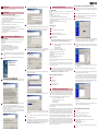
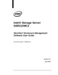
Unpacking the Storage System
Figure 1: Unpacking the Storage System
Permanently unplug the unit if you think that it has become damaged in any way and before you
move it.
• The enclosure can weigh up to 32kg (70.4lb). Do not try to lift it by yourself.
• Do not lift a populated enclosure by the handles on the Power Supply modules, they are not designed to support the weight of the populated enclosure.
• In order to comply with applicable safety, emission and thermal requirements no covers should
be removed and all bays must be fitted with plug-in modules.
Chassis Warning Label
Fan Module
Caution Label
3
Assemble two brackets (not handed) to rack as follows (see Figure 3):
a. Locate location pin at the rear end of the rail into rear rack post.
b. Extend rail to fit between the front and rear rack posts.
c. Attach to both front and rear of rack using supplied washers and screws.
d. The screws should be left loose enough to allow sideways movement of the rail.
e. Tighten the two clamping screws.
4
Mount enclosure into rack as follows:
a. Lift enclosure and align with rack rails.
b. Carefully insert the chassis slides into the rack rails and push fully home.
c. Tighten rear screws.
d. Withdraw enclosure until it reaches the hard stops (approximately 400mm).
e. Tighten front screws.
f. Return enclosure to fully home position and attach to rack using captive fasteners on
front flanges.
PSU Warning
Label
Power Supply Module Caution Label
5
•
•
•
•
•
•
•
•
•
The enclosure must only be operated from a power supply input voltage range of 100 - 240 VAC.
Operational:
Temperature Range: +5 °C to +40 °C
Relative Humidity: 8% to 80% non-condensing
The plugs on the power supply cord are used as the main disconnect device. Ensure that the
socket outlets are located near the equipment and are easily accessible.
The equipment must be operated with two working Power Supply modules.
A faulty Power Supply module must be replaced with a fully operational module within 24
hours.
When powered by multiple AC sources, disconnect all supply power for complete isolation.
The power connection should always be disconnected prior to removal of the Power Supply
module from the enclosure.
A safe electrical earth connection must be provided to the power cords. Check the grounding of
the enclosure before applying power.
Provide a suitable power source with electrical overload protection to meet the requirements laid
down in the technical specification.
Warning: Do not remove covers from the Power Supply module. Danger of electric shock inside.
Return the Power Supply module to your supplier for repair.
Drive 1
Drive 2
Drive 3
Drive 4
Drive 5
Drive 6
Drive 7
Drive 8
Drive 9
Drive 10
Drive 11
Drive 12
RS232
SAS Expansion
LEDs
StorView
Management Host 0 Port
Module
Host 1 Port
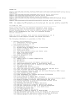
Connecting the AC Power
Battery
Module
Figure 4: Connecting the AC Power
Install the power cord(s) and secure them using the cable
strain relief bales.
PSU 0
4
PSU 1
Cooling Module
RAID Controller 0
Figure 5: Cable Strain Relief Bales
RAID Controller 1
Mounting the System into a Rack
6
A
Connecting Storage System to Host
Simplex: Single Host (Single HBA)
Caution: If this equipment is used in a manner not specified by the manufacturer, the protection
provided by the equipment may be impaired.
Battery Safety
SR1202
SJ1202
SJ1202
SJ1202
Warning: There is a danger of explosion if the battery is incorrectly replaced.
Dispose of used batteries in accordance with the manufacturer’s instructions and national
regulations.
2
Preparation of Site and Host Server
Before you begin, make sure the site where you intend to set up and use your SR1202 storage
system has the following:
• Standard AC power from an independent source or a rack power distribution unit with a UPS.
• Host computer with a standard Fibre Channel HBA (host bus adapter) with the latest BIOS and
drivers. Follow the instructions provided with your host bus adapter. Install the HBA and its driver
software, if necessary.
• At least 1 FC Cable LC-LC (Short Wave)
Figure 2: Securing Chassis Slides to Enclosure
The SR1202 Resource CD you received with your SR1202 Storage contains detailed information about planing, installing and operating the system. For latest information about your system and its components visit www.maxdata.com.
7
Power On
5
Power on the storage system, then power on the host system.
8
New Hardware Found at Startup - Installation
9
6
Enter the user name and password, then click the “Next” button.
The following are the minimum system requirements to install and use StorView on a Linux
platform:
• A personal computer or server with an Intel Pentium III type processor or compatible.
• 128 MB RAM.
• CD-ROM drive and 100 MB hard disk space.
• 256 color video adapter. (Minimum display settings should be 1024x768.)
• Operating systems - Red Hat® Enterprise Linux AS/ES (RHEL 3 & 4) 32 Bit only, or SuSE® Linux
Enterprise Server 8 and 9 32 Bit only.
• Web browser that is compliant with HTTP 1.1 and JavaScript 1.3 or later.
• Network adapter.
• SR1202
1
Log in as “root”.
2
Insert the Software and Manuals Disc into your CD drive.
3
Change directories to the software location.
cd [CDROM mount point path]/software/storview/linux
4
Execute the installer. Type:
./StorViewInstall
System Requirements
1
Insert the SR1202 Disc into your CD drive. The autorun program will automatically start
the navigation menu, click on the link for the hardware product (SR1202) which you have
installed.
2
Click the “Install StorView” link below the Software group. The installer Welcome screen
will appear.
Setting up the Embedded StorView Module: Microsoft Windows
Insert the SR1202 Resource Disc into your CD drive. The autorun program will automatically
1
start the navigation menu, click on the link for the hardware (SR1202) product which you
have installed.
2
Under Software click the “Embedded StorView Setup” link to begin the Setup Wizard.
3
You are presented with a Welcome screen with instructions to proceed. Review the
information and click the “Next” button.
4
The program will begin searching for Embedded StorView modules.
Installing StorView
This is the user name and password that will be established for the StorView login. You may
use up to 258 characters for the user name or password, and it is case sensitive. Be sure to
write down the user name and password, as it will be required to log into StorView.
Software Installation: MS Windows®
The following are the minimum system requirements to install and use StorView on Microsoft
Windows platforms:
• A personal computer or server with an Intel Pentium III type processor or compatible.
• 128 MB RAM.
• CD-ROM drive and 100 MB hard disk space.
• 256 color video adapter (Display settings should be set to 1024x768).
• Operating system - Microsoft® Windows® XP, 2000 (SP1 or later) and 2003.
• Web browser that is compliant with HTTP 1.1 and JavaScript 1.3 or later.
• Network adapter or a Microsoft Loop Back Adapter.
• SR1202.
Software Installation: Linux
System Requirements
Installation
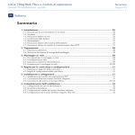
1. At startup if the “Found New Hardware” Wizard appears, click the Next button.
The “Install Hardware Device Drivers” window appears.
2. Choose the option that reads “Display a list of the known drivers for this device so that I can
choose a specific driver” and click the Next button.
The “Hardware Type” menu will appear.
3. Scroll down and select “System Devices” and click the Next button. Now you will have to choose
a driver.
4. Ensure that your SR1202 Resource Disc is in the CD-ROM drive.
Click the Browse button. Locate the CD-ROM and then locate the “drivers” folder.
Select the “xyratex_storage.inf” file. Click the Open button.
5. The “Select a Device Driver” window appears, under Model select “Xyratex F5402 RAID
Controller”. Click the Next button:
The message “Completing the Found New Hardware Wizard” will appear.
6. Click the Finish button.
10
If you selected the Global Manager, on the next screen enter your serial number and
activation code, then click the “Next” button.
Those embedded modules with their default password intact will be displayed with their
MAC address in an Uninitialized list window. If all discovered embedded modules have had
their default passwords changed, then you will be taken to the Initialized screen.
Note: If you receive a message that there is no match for your version of Linux, you will be
presented with a list to choose from of the available certified operating systems.
5
7
Accept the default installation directory and click the “Next” button, or to install in a different
directory click the “Browse” button and choose the directory for the software installation,
then click the “Next” button. The default directory is \Program Files\StorView.
Follow the on-screen prompts. The following utilities are provided to manage StorView:
5
/opt/StorView/StartStorView
/opt/StorView/StopStorView
/etc/rc.d/init.d/StorView {start|stop}
The directory where the software installs is the /opt/StorView directory.
To start StorView and the Apache web server type the following:
./StartStorView
To stop StorView and the Apache web server type the following:
./StopStorView
To determine if StorView is running, type the following:
ps -ef | grep -i StorView
Look for a running process named StorViewServer. There will be several of them. The Apache web
server process is named “httpd”.
The above command uses the recommended options, however you may use other options. Linux
also has a pgrep command. Type “pgrep StorViewServer” or “pgrep httpd” and get a list of process
IDs. No IDs means it is not running.
8
6
Choose the Start Menu folder and click the “Next” button.
You may accept the default name, “StorView” or create your own custom Start Menu folder
name by entering the desired name.
Start StorView by opening your web browser software and entering the IP address of the
host computer attached to the storage system followed by the port number. The format is
“HTTP://1<your_IP>:9292,” “HTTP://127.0.0.1:9292” or “HTTP://localhost:9292”. Refer to the
MAXDATA SR1202 M1 - StorView® RAID User Guide for more information.
If you wish to manually configure your network setting, enter the correction information in
the appropriate fields.
Enter a “new” password and confirm the new password. Click the “Configure” button.
6
Read the license agreement and click the “Yes” button to accept the terms of the license
and continue. Click “Cancel” if you do not wish to license the software at which time it will
cancel the installation.
1
Log in as “root”.
2
Change directories:
cd /opt/StorView
3
From the command prompt, type:
./UninstallStorView
11
The installation will begin. You may cancel the installation by clicking the “Cancel” button.
Choose the license manager type to install by selecting the appropriate radio button, and
click the “Next” button. If you choose Local Manager, skip to step 5.
The Local license is provided free without the requirement of a serial number and activation
code. It allows you to configure, manage, and monitor only a storage solution that is
attached to your local host system.
The Global license requires a serial number and activation code. The Global license allows
you to perform remote login, management and monitoring, and monitoring failover
capabilities plus Email alert notifications and SNMP traps.
Embedded StorView Initial Setup
If this is the first startup of the Embedded StorView module, you will probably need to configure
the network settings. The Embedded StorView module supports both DHCP and manual network
settings. By default the Embedded StorView module will look for a DHCP server to obtain an IP
address. If one is not found, it will search to determine if an IP address had been previously assigned.
If an address was not previously assigned, then the system defaults to an IP address of:
4
10.1.1.5 for the lower RAID Controller (Controller 0)
10.1.1.6 for the upper RAID Controller (Controller 1)
10.1.1.7 if an error is detected
Subnet Mask is 255.0.0.0
Select the MAC address of the embedded module you wish to start and click the “Launch
StorView” button.
Your default web browser will open with a login screen. Enter the login name and “new”
password then click “OK”.The StorView Main screen will open.
A tool is provided to configure new Embedded StorView modules. From Windows platforms it
is access via the Embedded link on the disc navigation menu and on Linux it is accessed via a
command line executable.
During the installation you will see several screens appear while the installer completes
the StorView installation, followed by the installation and configuration of the HTTP web
server software.
9
Once the installation is complete, a screen is displayed indicating the status of the
installation. Click the “Finish” button.
10
Start StorView by opening your web browser software and entering the IP address of the
host computer attached to the storage solution followed by the port number. The format
is “HTTP://<your_IP>:9292,” “HTTP://127.0.0.1:9292” or “HTTP://localhost:9292”. Refer to the
MAXDATA SR1202 M1 - StorView® RAID User Guide for more information.
If you have additional uninitialized embedded modules, select the next MAC address and
choose the appropriate settings from the previous step.
Once you have completed configuring all the uninitialized embedded modules and have
clicked the “Configure” button, the wizard will display a popup message indicating all
systems have been configured. It will then re-scan for systems and if none are found, you
will be taken to the Initialized screen. If someone plugs in a uninitialized module system to
the network (same subnet mask) during the time of the rescan or resets a system’s password
back to the defaults, you will be taken to the Uninitialized screen again.
Removing StorView from Linux Platforms
3
From the Uninitialized screen, select the MAC address of the embedded module you wish
to configure. If you wish to use a DHCP server to assign your IP address, click the check box
“Use DHCP”.
When the Embedded StorView Setup program is run, it will broadcast UDP packets and any
Embedded StorView module will reply with UDP packets containing their information. A list of
“uninitialized” systems is displayed. Uninitialized systems are those which have not had the default
user name and password changed. Even if a configuration is created with arrays and logical drives
but the login name and password have not been changed, it will still be considered an uninitialized
system. During the process of configuring an Embedded StorView module, you will be required to
enter a “new’ password and confirm that password. The default password is “password”.
The Embedded StorView module is identified by its MAC and IP address. It may be more helpful
during setup to configure one Embedded StorView module at a time. You will find the MAC address
located on a label affixed to the top of the controller case or by accessing the VT-100 text-based
menu function for Embedded StorView Menu mode and viewing the network settings. Note the
specific address of each controller in multiple controller environments and the location where that
specific controller is installed in the enclosure.
Setting up the Embedded StorView Module: Linux
1
Log in as “root”.
2
Insert the Software and Manuals Disc into your CD drive.
3
Change directories to the software location. Type:
cd [CDROM mount point path]/software/storview/embedded
4
Execute the Embedded StorView Setup Tool. From the command prompt, type:
./esvsetupcl-linux
Embedded StorView Setup Tool. v1.0
Entering Menu Mode.
5
Follow the on screen prompts. At the conclusion of the setup you will be instructed on how
to proceed.