1
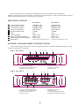
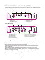
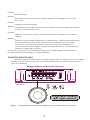
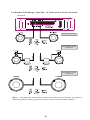
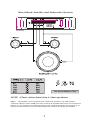
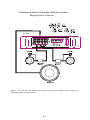
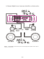
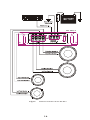
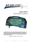
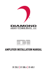
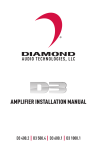
INTRODUCTION
The Diamond Audio D3 Series Amplifiers incorporate the following features:
Full frequency response with low distortion and exceptional signal to noise performance.
Advanced circuit design that features stereo, mono and mixed mode operation for use in a
variety of systems.
Variable high-pass/low-pass electronic crossover with a 12 dB per octave slope and fully
adjustable range (55 Hz~550 Hz).
Variable bass boost circuit to reinforce low frequency signals.
Adjustable input level controls with ground loop isolation accepting a wide range of input
signals.
Remote turn-on with "soft start" muting to prevent turn on "thump" .
Pulse-width modulated (PWM) MOSFET power supply with low AM RFI and protection
circuits for overheating and speaker shorts.
Nickel-plated input/output connectors and an external automotive type fuse.
Aluminum heat sink for efficient heat dissipation.
Low profile, compact size for space limited installs
TABLE OF CONTENTS
Description
Specifications
Power and Speaker Connections
Input Connections and Audio Control
Setting the Gain
Setting the Crossover
Setting the Bass Boost
Troubleshooting
System Diagrams
1
2
2
3
4
4
4
4
5
DESCRIPTION
The D3 Series Amplifiers provide a wide range of power and features that make them an
excellent choice for a variety of car audio sound system configurations.
D3 Amplifiers use an unregulated power supply for good control of output power. This
power supply design helps yield maximum power transfer with a minimum of heat loss.
On board noise filtration is used to keep unwanted noise from leaking into the system from the
amplifier. Each D3 amplifier comes complete with thermal, short, and load protection circuits
as well.
1
All connections and controls for the D3 Amplifiers are located on the end panels.
Plated connections ensure excellent conductivity and good looks. Easy to understand controls
make setting the amplifier up correctly an easy task.
SPECIFICATIONS
4 Ohm Stereo Output
2 Ohm Stereo Output
4 Ohm Mono Output
Frequency Response
Signal-to-Noise Ratio
THD
Input Sensitivity
High Level Input Sensitivity
Power Supply Operating Range
Dimensions
D3 400.2
D3 400.4
132w@1%THD
210w@1%THD
420w@1%THD
20Hz~20KHz
>100dB
.05%
250mV~2.5V
500mV~5V
10.8V~15.6V
2 1/4" H x 8 1/2" W x 12" L
57w@1%THD
88w@1%THD
182w@1%THD
20Hz~20KHz
>100dB
.05%
250mV~2.5V
500mV~5V
10.8V~15.6V
2 1/4" H x 8 1/2" W x 13" L
POWER AND SPEAKER CONNECTIONS
The following figures show the power/output end panels for each amplifier along with a key
to show the layout of each amp.
Fig.1 D3 400.2
1
2
3
4
5
1.Left Speaker Output
2.Right Front Speaker Output
3.Remote turn-on lnput
Fig.2 D3 400.4
1
2
7
8
6
4.Ground lnput
5.Battery+12v lnput
6.40 Amp Fuse
3
1.Left Front Speaker Output
2.Right Front Speaker Output
3.Remote Turn-on lnput
4.Ground lnput
4
5
6
5.Battery+12v lnput
6.40 Amp Fuse
7.Left Rear Speaker Output
8.Right Reart Speaker Output
2
INPUT CONNECTIONS AND AUDIO CONTROL
The following figures show the input/audio control end panels for each amplifier along with
a key to show the layout.
Fig.3 D3 400.2
1
4
3
2
5
1.RCA lnput jacks
2.Gain Control
3.Bass Boost Control
4.Crossover Frequency
6
7
5.X-Over Mode Switch
6.RCA Output Jacks
7.Power lndicator
Fig.4 D3 400.4
1
2
3
4
7
5
8
11
6
9
10
7.Front X-Over Frequncy Selection
8.Front X-Over Mode Switch
9.Rear X-Over Frequncy Selection
10.Rear X-Over Mode Switch
11.Power lndicator
1.Front RCA lnput jacks
2.Rear RCA lnput jacks
3.Front Gain Control
4.Rear Gain Control
5.Bass Boost Control
6.Channel lnput Selector
Gain Control Allows the nominal operating level of the amplifier to be set in conjunction
with the level of input voltage from the source unit. The D3 amplifiers will accommodate
low level (RCA) input ranging from 500 mV~5 V.
Bass Boost Acts like an equalizer with an adjustable gain fixed at 45 Hz. This adjustment
gives you up to 18 dB of boost at that frequency. This can be used to compensate for lack
of low-frequency response in the car audio environment.
Crossover Frequency Selection The crossover frequency is fully adjustable between
55 Hz and 550 Hz.
Crossover Mode Switch Switches crossover between off, low-pass, or high-pass.
When in the LP or HP position, a 12 dB per octave slope is implemented at the frequency
selected on the Frequency Knob.
Input Mode Switch Sets the input mode of the amplifier, depending on its purpose in the
system. Can be set to Stereo Mode, Bridged Mode, or Mono Mode.
Rear Channel Input Select (4 channel only) Allows channels 3 & 4 to use either set of
inputs (front or rear) for signal.
3
SETTING THE GAIN
The best way to set the gains on any amplifier is with an oscilloscope and test tone. Using
the scope will ensure the amplifier is not clipping and protect your system from being damaged
from being overdriven. If you have an oscilloscope and need help using it, feel free to call DAT
Technical Support for help.
Another way is with a multi-meter and test tone. Set the multi-meter to DC voltage, play
the test tone at 75% volume. Tune gains up until DC voltage is present, then back the gains back
down a little.
If an oscilloscope, multi-meter, or test tone is not available, find out the output signal
voltage of the head unit. Match the gain knob with that amount of voltage. It should be
between 500 mV and 5 V. If it is above 5 V, the head unit has too much signal and the amp will
clip even with the gain set at minimum. Turn system on and volume to 75%, if there is
noticeable distortion, gains should be tuned down some.
SETTING THE CROSSOVER
Select LP or HP using the Crossover Mode Switch, select desired frequency by turning the
Frequency Knob.
SETTING THE BASS BOOST
If there is a noticeable lack of low end frequency, the bass boost can be used to raise the
level of bass in the system. Turn the system on to normal listening levels and raise the bass boost
until the level of bass is satisfactory.
Caution: If "popping" , "crackling" ,or any other unusual noise is heard from the system
when using the bass boost, immediately turn the boost down to avoid damaging components
in the system. Also, if the bass sounds "muddy" or distorted, turn the bass boost down.
TROUBLESHOOTING
Problem
No Audio Output
Solution
Low or no turn-on voltage. Check remote connections at amp and head unit.
Check remote voltage at amp with multi-meter, there should be around 12 volts when
head unit is on.
Blown Fuse. Check both main system fuse and amplifier fuse. If blown, replace with
fuse of same type and rating.
Loose Connections. Check all power and signal wires to make sure they have solid
connection.
Speaker lead shorted. Check all speaker wire to make sure they are not shorted out
somewhere.
Blown speakers. Check speaker impedance with multi-meter, if the woofer is blown,
it will read a dead short.
Problem
Amplifier cycles on and off.
Solution
Thermal protection circuits are shutting the amplifier off. Check location of amplifier
for adequate ventilation. Check impedance at amplifier for correct load. Check
voltage at amplifier for low voltage.
4
Problem
Distorted audio.
Solution
Check that gains are set correctly. Inspect speakers for damaged cones or bad
voice coils.
Problem
Amplifier fuse keeps blowing.
Solution:
Check all power and signal wires for a short. Make sure power and ground wires are
correctly connected to the amp.
Problem
Whining, ticking, or any other unwanted noise present in system when engine is
running.
Solution
Amplifier may be picking up alternator or radiated noise. Make sure all signal wires
are separated from power wires. Check all signal and power wires for a sold
connection. Check all ground wires to make sure they have a solid ground.
Check alternator and/or voltage regulator for solid connections. Check battery for
adequate voltage and connection.
If you have any questions or need added help with your new D3 Amplifier, please feel free
to call Diamond Technical Support at 1-866-328-2834.
SYSTEM DIAGRAMS
The Diamond Audio D3 400.2(Fig.5 to 7)and D3 400.4(fig.8 to 13)2 and 4-channel car audio
amplifiers can be used in a variety of system applications.Here are some examples to plan
your own installation
Bridged-Mono Subwoofer System
D3 400.2
Low HIGH FULL
Fig.5
In this application the amplifier is bridged for mono operation to drive a subwoofer
5
2-Channel Full-Range, Satellite, of Subwoofer Stereo System
D3 400.2
Set X-Over Mode to FULL
Low HIGH FULL
Set X-Over Mode to FULL
ADJUST FREQ to speaker
Specifications
Low HIGH FULL
Set X-Over Mode to LOW
ADJUST FREQ to speaker
Specifications
Low HIGH FULL
Fig.6 In this application, the amplifier is used in stereo and drives two full-range (or satellite or
subwoofer) speakers. NOTE A passive crossover must be used with satellite speakers.
6
Mixed-Mode Satellite and Subwoofer System
D3 400.2
Low HIGH FULL
Set X-Over Mode to FULL.
NOTE
Chart values based on 4 ohm speakers.
Fig.7 The amplifier can be configured for a mixed-mode operation. The table provides
component values to create a 6dB per octave crossover at specified frequencies. Use components
that have a +
- 5% tolerance and capacitors rated at 100V. NOTE Choose the same frequency for
both LP and HP crossovers. Do not overlap frequencies, as this may damage the amplifier.
7
D3 400.2
Fig.8
Electrical connections for the D3 400.2
8
SOURCE
2CH BASS 2CH 4CH
LOW HIGH FULL
LOW HIGH FULL
D3 400.4
Fig.9
ln this application, the D3 400.4 was used as a 4-channel amplifier to drive four
full-range speakers in stereo.
9
4-Channel Stereo System
2-Channel High-Pass. 2-Channel Low-Pass
SOURCE
2CH BASS 2CH 4CH
D3 400.4
LOW HIGH FULL
LOW HIGH FULL
Fig.10
ln this 4-channel system, the D3 400.4 drives a pair of statellites and a pair of
subwoofers. Note the filter settings.
10
2-Channel Stereo System with Low-pass
Bridged Mono Channel
SOURCE
2CH BASS 2CH 4CH
LOW HIGH FULL
LOW HIGH FULL
D3 400.4
Fig.11 The D3 400.4 can alse be used to drive a pair of stereo satellites and a single mono
subwoofer. Note the filter settings
11
2-Channel High Power Systems (Satellite or Subwoofer)
SOURCE
2CH BASS 2CH 4CH
LOW HIGH FULL
D3 400.4
LOW HIGH FULL
SOURCE
2CH BASS 2CH 4CH
LOW HIGH FULL
LOW HIGH FULL
Fig.12
The D3 400.4 can also be set up as a 2-channel high-power amplifier to drive a pair of
satellites (or subwoofers).
12
Mixed-Mode System On Rear
Speakers On Front
Full-Range
SOURCE
2CH BASS 2CH 4CH
D3 400.4
NOTE
LOW HIGH FULL
LOW HIGH FULL
Chart values based on 4 ohm speakers.
Fig.13
The amplifier can be configured for a mixed-mode operation on either channels 1/2 or 3/4
amplifier sections. The table provides component values to create a 6dB per octave crossover at
specified frequencies. Use the same frequency for both LP and HP crossovers. Do not overlap
frequencies, as this may damage the amplifier.
13
D3 400.4
Fig.14
Electrcal connections for the D3 400.4
14
LIMITED WARRANTY STATEMENT
Diamond Audio Technology, Inc. (DAT) warrants all DAT products to be
free of defects in material and workmanship for a period of one (1) year from
the date of original purchase provided they are purchased from an authorized
DAT retailer in the United States. However, the effective warranty period will
be three (3) years if the products were purchased from and installed by an
authorized DAT reta il er.
R
DIAMOND
A U D I O T E C H NO L O G Y
Listen as the
Artist Intended
Head Office
410 5. Benson Lane
Chandler, AZ 85224
Tel 480-813-6200
Fax 480-813-6210
Service/Tech Support
Toll Free 1-886-328-2834
[email protected]
What is covered: Parts and labor to effect repair or, at the sole discretion
of DAT, replacement of either any malfunctioning or defective part(s) or the
entire system should the system or any component part(s) thereof fail to
perform as designed. Includes return freight via ground transportation to
destinations within the United Stat es .
What is NOT covered: Installation or setup and repair or replacement of
the system or any parts thereof which, in DAT's judgment, fail or become
damaged as a result of negligence, improper use, abuse, unauthorized
modification or service, improper or inadequate packaging during shipment,
installation by a non-authorized dealer, accident, or use for any purpose
other than those for which this product was originally intended, or where the
model's serial number has been r emoved, al tered or def aced.
Who is covered: Original purchaser so long as they reside in the United
States and can provide proof of the original date of purchase
( e . g . , s t o r e r e c e i p t ) f r o m a n a ut h o r i z e d D A T r e t a i l e r .
OUTSIDE THE U NITED STAT ES
Customers outside the United States should contact their local sales
office to obtain information on prices, exchange unit availability, instructions,
serv ice and warran ty/non-warrant y repairs.
Repair or replacement under this warranty is the exclusive remedy of
the consumer. DAT shall not be liable for any incidental or consequential
damages for breach of any expressed or implied warranty on this product.
Except to the extent prohibited by applicable law, any implied warranty of
merchantability or fitness for a particular purpose on this product is limited
in duration to the duration of this warranty. Some states do not allow the
exclusion or limitation of incidental or consequential damages, or allow
limitations on how long an implied warranty lasts, so the above limitations
or exclusions may not apply to you. This warranty gives you specific legal
rights and you may also have other rights that may vary from state to state.
HOW TO OBTAIN WARRANTY SERVICE
www.diamondaudio.com
In the event a DAT product should require servicing, you
should (a) visit an authorized DAT retailer or (b) call the DAT
Service Dept. at (866) 328 2834. To be eligible for warranty
service within a three (3) year period, the accompanying
receipt of original purchase from an authorized DAT retailer
must specifically note that dealer installation was provided.
Product returned for repair/service must be properly
packaged and clearly marked with the Return Authorization
(RA) number issued by DAT. If the RA number is not clearly
marked on the package or no RA number was issued by DAT,
the product may be refused upon delivery. DAT does not
assume responsibility for lost or misdirected product.
C
2003 Diamond Audio Technology. All rights reserved.
R
DIAMOND
AUDIO TECHNOLOGY
400.2 & 400.4
Owner's Guide
Serial Number
Date of Purchase
www.diamondaudio.com