1
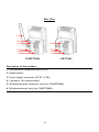
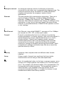
Conceptronic
CNETCAM2 & C54NETCAM2
Network Camera
Advanced Installation Guide
&
Software User Guide
Version 1.0
P REFACE
Thank you for purchasing the Conceptronic Network Camera, a powerful and
high-quality image wireless network camera. The camera can be installed as a
standalone system within your application environment easily and quickly, and
supports remote management function so that you can access and control it
using a Web browser on your PC.
This Advanced Installation Guide provides you with the instructions and
illustrations on how to use your camera, which includes:
Chapter 1 Introduction to Your Camera describes the features of the camera.
You will also know the components and functions of the camera.
Chapter 2 Hardware Installation helps you install the camera according to
your application environment. You can use this camera at home, at
work, at any where you want.
Chapter 3 Accessing the Camera lets you start using your camera without
problem. The camera can be set up easily and work within your
network environment instantly.
Chapter 4 Configuring the Camera guides you through the configuration of the
camera using the web browser on your PC.
Chapter 5 Appendix provides the specification of the camera and some useful
information for using your camera.
Note: The illustrations and configuration values in this guide are for reference
only. The actual settings depend on your practical application of the
camera.
-1-
Contents
PR E FA CE ................................................... 1
IN TR O D UCT I O N TO Y O UR CA M ER A ..................... 3
1.1
1.2
1.3
1.4
CHECKING THE PACKAGE CONTENTS ....................................... 3
GETTING TO KNOW YOUR CAMERA......................................... 4
FEATURES AND BENEFITS .................................................. 6
SYSTEM REQUIREMENT .................................................... 7
HA R D WA R E I N STA L LA TI O N .............................. 8
2.1
2.2
2.3
INSTALLING THE CAMERA STAND ........................................... 8
CONNECTING THE CAMERA TO LAN/WLAN................................ 9
APPLICATIONS OF THE CAMERA ...........................................10
A CC ES S I NG TH E CA M E R A .............................. 1 1
3.1
3.2
3.3
USING IP FINDER ........................................................11
ACCESSING TO THE CAMERA ..............................................12
CONFIGURING THE IP ADDRESS OF THE PC ................................16
CO N F IG UR I NG TH E C A MER A ........................... 1 7
4.1
4.2
4.3
4.4
4.5
4.6
4.7
4.8
4.9
4.10
USING THE WEB CONFIGURATION .........................................17
USING SMART WIZARD ...................................................19
BASIC SETUP ............................................................22
NETWORK SETTINGS .....................................................26
SETTING UP VIDEO .......................................................32
EVENT SERVER CONFIGURATION ..........................................34
MOTION DETECT .........................................................36
EVENT CONFIG ..........................................................37
TOOLS ..................................................................41
INFORMATION ............................................................43
S O FT WA R E I N ST A LLA T IO N ............................ 4 5
U SI N G UL TR A V I E W ..................................... 4 8
TO LAUNCH THE PROGRAM .......................................................48
ITEM FEATURES .................................................................49
TO ADD A CAMERA...............................................................53
TO REMOVE A CAMERA ...........................................................56
TO LINK TO THE WEB PAGE OF THE CAMERA ......................................56
TO RECORD VIDEO ...............................................................57
TO CONFIGURE THE RECORDING SETTINGS ........................................59
TO PLAYBACK THE RECORDED VIDEO ..............................................61
TO SET UP MOTION DETECTION OPTIONS ..........................................62
INFORMATION ...................................................................64
A PPE N D IX ................................................ 6 5
A.1
A.2
A.3
SPECIFICATION ...........................................................65
GLOSSARY OF TERMS .....................................................67
GNU-GPL LICENSE INFORMATION ........................................75
-2-
C HAPTER 1
I NTRODUCTION TO Y OUR C AMERA
1.1 Checking the Package Contents
The following items should be present in the package of the Conceptronic
CNETCAM2 / C54NETCAM2:
•
•
•
•
•
•
•
Conceptronic CNETCAM2 / C54NETCAM2 Network Camera Camera Stand
Mounting screws with wall plugs for product stand
Power supply (5V DC, 2.5A)
Network cable (RJ-45 type)
Product CD-ROM
Wireless antenna (only applies to the C54NETCAM2)
This Quick Installation Guide
Note: Once any item contained is damaged or missing, contact the authorized
dealer of your locale.
-3-
1.2 Getting to Know Your Camera
Front View
2
2
1
1
C54NETCAM2
CNETCAM2
Description of the numbers
1. Adjustable lens.
2. LEDs for ‘Power’ (top) and ‘Activity’ (bottom).
-4-
Rear View
6
5
4
4
3
2
1
3
2
1
C54NETCAM2
CNETCAM2
Description of the numbers
1. LAN network connection port (RJ45).
2. Reset button.
3. Power supply connector (5V DC, 2.5A).
4. Connector for camera stand.
5. Wireless antenna connector (only for C54NETCAM2).
6. Wireless antenna (only for C54NETCAM2).
-5-
1.3 Features and Benefits
Surveillance Supported
The camera supports “nightshot mode” to deliver clearer images in the
dark environment. Enable motion detection and setup automated email
alerts and upload FTP for security.
Remote Control Supported
By using a standard Web browser or the bundled Ultra View software
application, the administrator can easily change the configuration of the
camera via Intranet or Internet. In addition, the camera can be upgraded
remotely when a new firmware is available. The users are also allowed to
monitor the image and take snapshots via the network.
Multiple Platforms Supported
The camera supports multiple network protocols, including TCP/IP, SMTP email, HTTP, and other Internet related protocols. Therefore, you can use
the camera in a mixed operating system environment, such as Windows
2000 and Windows XP.
Multiple Applications Supported
Through the remote access technology, you can use the cameras to monitor
various objects and places for your own purposes.
For example, babies at home, patients in the hospital, offices and banks,
and more. The camera can capture both still images and video clips, so that
you can keep the archives and restore them at any time.
-6-
1.4 System Requirement
Networking
LAN:
10Base-T Ethernet or 100Base-TX Fast Ethernet.
WLAN:
IEEE 802.11b/g.
Accessing the Camera using Web Browser
Platform:
Microsoft® Windows® 2000/XP/Vista
CPU:
Intel Pentium III 350MHz or above
RAM:
128MB
Resolution:
800x600 or above
User Interface: Microsoft® Internet Explorer 6.0 or above
Apple Safari 2 or above
Mozilla Firefox 2.00 or above
Accessing the Camera using Ultra View
Platform:
Microsoft® Windows® 2000/XP/Vista.
Hardware Requirement:
1 camera connected: Intel Pentium III 800MHz; 512MB RAM
2 ~ 4 cameras connected: Intel Pentium 4 1.3GHz; 512MB RAM
5 ~ 8 cameras connected: Intel Pentium 4 2.4GHz; 1GB RAM
9 ~ 16 cameras connected: Intel Pentium 4 3.4GHz; 2GB RAM
Resolution:
1024x768 or above
Note: If you connect multiple cameras to monitor various places simultaneously,
you are recommended to use a computer with higher performance.
-7-
C HAPTER 2
H ARDWARE I NSTALLATION
2.1 Installing the Camera Stand
The camera comes with a camera stand, which uses a swivel ball screw head to
lock to the camera’s screw hole. When the camera stand is attached, you can
place the camera anywhere by mounting the camera through the three screw
holes located in the base of the camera stand.
The Camera Stand
-8-
2.2 Connecting the Camera to LAN/WLAN
Use the provided Ethernet cable
to connect the camera to your
local area network (LAN).
When you connect the AC power
adapter, the camera is powered
on automatically. You can verify
the power status from the Power
LED on the front panel of the
camera.
Once connected, the Link LED
starts flashing green light and the
camera is on standby and ready
for use now.
Connecting the Ethernet Cable
C54NETCAM2 ONLY:
If you use a wireless network in
your application environment, you
need to attach the included
external antenna to the camera.
When the camera is powered on,
the camera will automatically
search any access point with
“default” SSID.
Connecting the External Antenna
(C54NETCAM2 Only)
Note: If the camera cannot connect to your wireless network, you need to
install the camera in LAN and proceed with WLAN settings.
-9-
2.3 Applications of the Camera
The camera can be applied in multiple applications, including:
Monitor local and remote places and objects via Internet or Intranet.
Capture still images and video clips remotely.
Upload images or send email messages with the still images attached.
The following diagram explains one of the typical applications for your camera
and provides a basic example for installing the camera.
*
*Please enclosed by waterproof
housing when using in outdoor
Home Applications
- 10 -
C HAPTER 3
A CCESSING
THE
C AMERA
3.1 Using IP Finder
The camera comes with a conveniently utility, IP Finder, which is included in
the Installation CD-ROM, allowing you to search the camera on your network
easily.
1. Insert the Installation CD-ROM into your computer’s CD-ROM drive to initiate
the Auto-Run program.
2. Click the IP Finder item to launch the utility. The control panel will appear
as below.
•
•
•
Click ‘Search’ to find the IP address of the connected camera(s).
Click ‘Change IP’ to modify the IP address of the selected camera.
Click ‘Exit’ to close the utility.
3. Once you get the IP address of the camera, launch the Web browser or Ultra
View to access your camera.
- 11 -
3.2 Accessing to the Camera
Whenever you want to access the camera:
1. Open the Web browser on your computer (for example, Microsoft Internet
Explorer in this guide)
2. Type the default IP address (192.168.0.40 for CNETCAM2 or 192.168.0.45 for
C54NETCAM2) or the IP address found by IP Finder in the Address bar, and
then press [Enter].
After you login into the Web Configuration of the camera, the main page will
appear as below:
In the main menu, you can select the following options:
ActiveX – View the network camera in ActiveX Mode
Java Applet – View the network camera in Java Mode
Setup – Open the configuration pages of the network camera
- 12 -
When you select ‘ActiveX’ in the main menu, the following screen will be
shown:
Note: You need to accept the ActiveX applet in order to see the camera image.
The following options are available:
-
Home – Return to the main page
-
Manual Record – Record the displayed camera image
-
Snapshot – Make a snapshot of the displayed camera image
-
Browse – Browse for a destination folder for above options
-
1x, 2x, 3x – Use Digital Zoom on the displayed camera image
-
Nightmode – Initialize Nightmode
- 13 -
When you select ‘Java Applet’ in the main menu, the following screen will be
shown:
Note:
You need to accept the Java applet in order to see the camera image.
The following options are available:
-
Home – Return to the main page
-
Nightmode – Initialize Nightmode
- 14 -
When you select ‘Setup’ in the main menu, the following screen will be shown:
3. When the login window appears, enter the default User name (admin) and
password (admin) and press ‘OK’ to access the camera’s Web Configuration.
- 15 -
3.3 Configuring the IP Address of the PC
If you are failed to access to the camera, please check the IP address of your
computer. When you connect the camera to your computer directly to proceed
with configuration of the camera, you need to set up the IP addresses to be in
the same segment for the two devices to communicate.
1. On your computer, click Start > Control Panel to open the Control Panel
window.
2. Double-click Network Connection to open the Network Connection window.
3. Right-click Local Area Connection and then click Properties from the
shortcut menu.
4. When the Local Area Connection Properties window appears, select the
General tab.
5. Select Internet Protocol [TCP/IP] and then click Properties to bring up the
Internet Protocol [TCP/IP] Properties window.
6. To configure a fixed IP address that is within the segment of the camera,
select the Use the following IP address option. Then, enter an IP address
into the empty field. The suggested IP address is 192.168.0.x (x is 0~254
except 30), and the suggested Subnet mask is 255.255.255.0.
7. When you are finished, click OK.
- 16 -
C HAPTER 4
C ONFIGURING
THE
C AMERA
4.1 Using the Web Configuration
You can access and manage the camera through the Web browser and the
provided software application Ultra View. This chapter describes the Web
Configuration, and guides you through the configuration of the camera by using
the web browser.
To configure the camera, click ‘Setup’ on the main page of Web Configuration:
When the login window appears, enter the default User name (admin) and
password (admin) and press ‘OK’ to access the camera’s Web Configuration.
- 17 -
When the username and password are OK, the Web Configuration will start from
the Basic page.
The Web Configuration contains the settings that are required for the camera in
the left menu bar, including Smart Wizard, Basic, Network, Video, Event
Server, Motion detect, Event Config, Tools, and Information.
- 18 -
4.2 Using Smart Wizard
The camera’s Smart Wizard lets you configure your camera easily and quickly.
The wizard will guide you through the necessary settings with detailed
instructions on each step.
To start the wizard, click Smart Wizard in the left menu bar.
Step 1. Camera Settings
Enter the name for
the camera and
place.
Enter the
administrator
password.
Step 2. IP Settings
Select the IP setting
according to your
network: DHCP,
Static IP, or PPPoE.
- 19 -
Step 3. Email Settings
Enter the required
information to be
able to send email
with image.
Step 4. Wireless Networking
Note:
This page is only shown in the configuration of the C54NETCAM2.
Select Enable to
enable the wireless
function of the
camera, and then
complete the
required settings.
- 20 -
Step 5. Confirm Settings
This step shows the configuration of your camera. When you confirm the
settings, click Apply to finish the wizard and reboot the camera. Otherwise,
click Prev to go back to the previous step(s) and change the settings; or click
Cancel to end the wizard and discard the changes.
- 21 -
4.3 Basic Setup
The Basic menu contains three sub-menus that provide the system settings for
the camera, such as the Camera Name, Location, Date & Time, and User
management.
Basic >> System
Basic
- Camera Name: Enter a descriptive name for the camera.
- Location: Enter a descriptive name for the location used by the camera.
Indication LED
This item allows you to set the LED illumination as desired. There are two
options: Normal and OFF.
- 22 -
Basic >> Date & Time
Date & Time
- TimeZone: Select the proper time zone for the region from the pull-down
menu.
- Synchronize with PC: Select this option and the date & time settings of
the camera will be synchronized with the connected computer.
- Synchronize with NTP Server: Select this option and the time will be
synchronized with the NTP Server. You need to enter the IP address of the
server and select the update interval in the following two boxes.
- Manual: Select this option to set the date and time manually.
- 23 -
Basic >> User
Administrator
To prevent unauthorized access to the camera’s Web Configuration, you are
strongly recommend to change the default administrator password. Type
the administrator password twice to set and confirm the password.
General User
- User Name: Enter the user’s name you want to add to use the camera.
- Password: Enter the password for the new user.
When you are finished, click Add/Modify to add the new user to the
camera. To modify the user’s information, select the one you want to
modify from UserList and click Add/Modify.
- UserList: Display the existing users of the camera. To delete a user,
select the one you want to delete and click Delete.
- 24 -
Guest
- User Name: Enter the guest’s name you want to add to use the camera.
- Password: Enter the password for the new guest.
- UserList: Display the existing guests of the camera. To delete a user,
select the one you want to delete and click Delete.
Note: The “General User” can access the camera and control the Function
buttons of the camera’s Web Configuration; the “Guest’ can only view
the live view image from the main page of the Web Configuration while
accessing the camera. Only the “Administrator” is allowed to configure
the camera through the Web Configuration.
- 25 -
4.4 Network Settings
The Network menu contains three sub-menus that provide the network settings
for the camera, such as the IP Setting, DDNS Setting, IP Filter, and Wireless
network.
Network >> Network
IP Setting
This item allows you to select the IP address mode and set up the related
configuration.
- DHCP: Select this option when your network uses the DHCP server. When
the camera starts up, it will be assigned an IP address from the DHCP
server automatically.
- 26 -
- Static IP: Select this option to assign the IP address for the camera
directly. You can use IP Finder to obtain the related setting values.
IP
Enter the IP address of the camera. The
default setting is 192.168.0.40 for the
CNETCAM2 and 192.168.0.45 for the
C54NETCAM2.
Subnet Mask
Enter the Subnet Mask of the camera. The
default setting is 255.255.255.0.
Default Gateway
Enter the Default Gateway of the camera.
The default setting is 192.168.0.1.
Primary/
Secondary DNS
DNS (Domain Name System) translates
domain names into IP addresses. Enter the
Primary DNS and Secondary DNS that are
provided by ISP.
- PPPoE: Select this option when you use a direct connection via the ADSL
modem. You should have a PPPoE account from your Internet service
provider. Enter the User Name and Password. The camera will get an IP
address from the ISP as starting up.
Note: Once the camera get an IP address from the ISP as starting up, it
automatically sends a notification email to you. Therefore, when you
select PPPoE as your connecting type, you have to set up the email or
DDNS configuration in advance.
DDNS Setting
With the Dynamic DNS feature, you can assign a fixed host and domain
name to a dynamic Internet IP address. Select the Enable option to enable
this feature. Then, select the Provider from the pull-down list and enter the
required information in the Host Name, User Name, and Password boxes.
Please note that you have to sign up for DDNS service with the service
provider first.
- 27 -
UPnP
The camera supports UPnP (Universal Plug and Play), which is a set of
computer network protocols that enable the device-to-device
interoperability. In addition, it supports port auto mapping function so that
you can access the camera if it is behind an NAT router or firewall. Select
the Enable option to enable this feature.
Ports Number
- HTTP Port: The default HTTP port is 80.
NOTE If the camera is behind an NAT router of firewall, the suggested to be
used is from 1024 to 65535.
- 28 -
Network >> IP Filter
The IP Filter setting allows the administrator of the camera to limit the users
within a certain range of IP addresses to access the camera.
Start/End IP Address
Assign a range of IP addresses that are not allowed to access the camera by
entering the Start IP address and End IP address. When you are finished,
click Add to save the range setting. You can repeat the action to assign
multiple ranges for the camera.
For example, when you enter 192.168.0.50 in Start IP Address and
192.168.0.80 in End IP Address, the user whose IP address located within
192.168.0.50 ~ 192.168.0.80 will not be allowed to access the camera.
Deny IP List
The list displays the range setting(s) of IP addresses that are not allowed to
access the camera. To clear the setting, select a range of IP addresses from
the list and click Delete.
- 29 -
Network >> Wireless Setting
Wireless
The camera supports WLAN while you use the wireless network. Select the
Enable option to enable this feature.
- Network ID (SSID}: Keep the default setting of this option to connect the
camera to any access point under the infrastructure network mode. To
connect the camera to a specified access point, set a SSID for the camera
to correspond with the access point’s ESS-ID. To connect the camera to an
Ad-Hoc wireless workgroup, set the same wireless channel and SSID to
match with the computer’s configuration.
Click Site Survey to display the available wireless networks, so that you
can easily connect to one of the listed wireless networks.
- Wireless Mode: Select the type of wireless communication for the camera:
Infrastructure or Ad-Hoc.
- Channel: Select the appropriate channel from the list.
- Authentication: Select the authentication method to secure the camera
from being used by unauthorized user: Open, Shared-key, WPA-PSK, and
WPA2-PSK. The following table explains the four options:
- 30 -
Open
The default setting of Authentication mode,
which communicates the key across the
network.
Shared-key
Allow communication only with other devices
with identical WEP settings.
WPA-PSK/
WPA2-PSK
WPA-PSK/WPA2-PSK is specially designed for the
users who do not have access to network
authentication servers. The user has to
manually enter the starting password in their
access point or gateway, as well as in each PC
on the wireless network.
If you select Open or Shared-key as the Authentication mode, you need
to complete the following settings:
Encryption: Select the WEP option to enable the data encryption
feature to secure the camera within the wireless network.
Format: Once you enable the Encryption feature, you need to
determine the encryption format by selecting ASCII or HEX. ASCII
format causes each character you type to be interpreted as an eight-bit
value. Hex format causes each pair of characters you type to be
interpreted as an eight-bit value in hexadecimal (base 16) notation.
Key Length: Select the WEP key length you use: 64 bits or 128 bits.
WEP Key 1/2/3/4: Enter the WEP key(s) in the following boxes.
If you select WPA-PSK or WPA2-PSK as the Authentication mode, you
need to complete the following settings:
Encryption: Select TKIP or AES. TKIP (Temporal Key Integrity Protocol)
changes the temporal key every 10,000 packets to insure much greater
security than the standard WEP security. AES (Advanced Encryption
Standard) is used to ensure the highest degree of security and
authenticity for digital information.
Pre-Shared Key: This is used to identify each other in the network.
Enter the name in the box, and this name must match the Pre-shared
key value in the remote device.
- 31 -
4.5 Setting up Video
The Video menu contains two sub-menus that provide the video settings for the
camera.
Video >> Camera
Image Setting
- Brightness: Adjust the brightness level from 0 ~ 100.
- Contrast: Adjust the contrast level from 0 ~ 100.
- Saturation: Adjust the colors level from 0 ~ 100.
Click Default to restore the default settings of the three options above.
- Mirror: Select the Horizontal option to mirror the image horizontally.
Select the Vertical option to mirror the image vertically.
- Light Frequency: Select the proper frequency according to the camera’s
location: 50Hz, 60Hz, or Outdoor.
- 32 -
Overlay Setting
- Includes Date & Time: Select this option to display the date & time
stamp on the live view image.
- Enable Opaque: Select this option to set a black background to the
displayed date & time stamp.
Video >> Video
MJPEG
- Video Resolution: Select the desired video resolution from the three
formats: VGA, QVGA and QQVGA. The higher setting (VGA) obtains better
video quality while it uses more resource within your network.
- Video Quality: Select the desired image quality from five levels: Lowest,
Low, Medium, High, and Highest.
- Frame Rate: Select Auto or a proper setting depending on your network
status.
- 33 -
4.6 Event Server Configuration
The Event Server menu contains two sub-menus that allow you to upload images
to FTP, and send emails that include still images.
When you complete the required settings for FTP, or Email, click Test to test
the related configuration is correct or not. Once the camera connects to the
server successfully, click Apply.
Event Server Setting>> FTP
FTP
- Host Address: Enter the IP address of the target FTP server.
- Port Number: Enter the port number used for the FTP server.
- User Name: Enter the user name to login into the FTP server.
- Password: Enter the password to login into the FTP server.
- Directory Path: Enter the destination folder for uploading the images. For
example, /Test/.
- Passive Mode: Select the Enable option to enable passive mode.
- 34 -
Event Server Setting >> Email
Email
- SMTP Server Address: Enter the mail server address. For example,
mymail.com.
- Sender Email Address: Enter the email address of the user who will send
the email. For example, [email protected].
- Sender User Name: Enter the user name to login the mail server.
- Sender Password: Enter the password to login the mail server.
- Receiver #1 Email Address: Enter the first email address of the user who
will receive the email.
- Receiver #2 Email Address: Enter the second email address of the user
who will receive the email.
- 35 -
4.7 Motion Detect
The Motion Detect menu contains the command and option that allow you to
enable and set up the motion detection feature of the camera. The camera
provides two detecting areas.
To enable the detecting area, select Window 1 or 2 from the pull-down list,
and then select Enable. When the detecting area is enabled, you can use the
mouse to move the detecting area and change the area coverage.
- Name: Assign a name to the detecting area.
- Threshold: Move the slide bar to adjust the level for detecting motion to
record video.
- 36 -
4.8 Event Config
The Event Config menu contains four sub-menus that provide the commands to
configure event profiles.
Event Configuration >> General Setting
- Snapshot/Recording Subfolder: You can assign a given sub-folder for
captured file. Otherwise, leave this option blank to use the default
setting.
- 37 -
Event Configuration >> Arrange Schedule Profile
This sub-menu displays the scheduled profile(s). To customize the profile, click
Add and then enter a descriptive name for the profile in the prompt dialog
window. After entering the profile name, click OK and the profile is added to
the Schedule Profiles list. To delete the profile, select the profile in the list and
click Delete.
- Profile Name: Display the profile name that you select in the Schedule
Profiles list.
- Weekdays: Select the weekday(s) that you want to separately assign in
the schedule profile. The weekday that has been assigned will be
displayed with green color.
- Time List: Display the time period that you have assigned within the
selected weekday. To assign the same time period to every weekday,
click Add this to all weekdays; click Delete this from all weekdays to
remove the selected time period from every weekday. Click Delete to
remove the selected time period.
- Start/End Time: Enter the start and end time and then click Add to assign
a time period within in the selected weekday.
- 38 -
Event Configuration >> Motion Detect Trigger
Select the Enable option to enable the trigger function of the camera, so that
you can send captured images within the detecting area to the FTP server, or
email receiver. You have to configure corresponding settings, such as FTP server
and email server, to enable this feature.
- Schedule Profile: Select a schedule profile from the pull-down list.
- Action: Select the destination that the captured images will be sent to:
Send Email, or FTP Upload.
- 39 -
Event Configuration >> Schedule Trigger
You can separately configure the schedule for trigger function of the camera by
Email, or FTP. Select the Enable option on each item, and then select a
Schedule Profile from the pull-down list and set the Interval time.
- 40 -
4.9 Tools
The Tools menu provides the commands that allow you to restart or reset the
camera. You can also backup and restore your configuration, and upgrade the
firmware for the camera.
Factory Reset
Click Reset to restore all factory default settings for the camera.
System Reboot
Click Reboot to restart the camera just like turning the device off and on.
The camera configuration will be retained after rebooting.
Configuration
You can save your camera configuration as a backup file on your computer.
Whenever you want to resume the original settings, you can restore them by
retrieving the backup file.
- Backup: Click Get the backup file to save the current configuration of
the camera.
- Restore: Click Browse to locate the backup file and then click Restore.
- 41 -
Update Firmware
This item displays the current firmware version. You can upgrade the
firmware for your camera once you obtained a latest version of firmware.
- Select the firmware: Click Browse to locate the backup file and then
click Update.
Note: Make sure to keep the camera connected to the power source during the
process of upgrading firmware. Otherwise, the camera might be damaged
because of failure of upgrading firmware.
- 42 -
4.10 Information
The Information menu displays the current configuration and events log of the
camera.
Device Info
Display the Basic, Video, Network, and Wireless settings of the camera.
System Log
The Logs table displays the events log recorded by the system.
- 43 -
Software User Guide
This Software User Guide provides detailed instructions on operating Ultra View,
a customized software application with a user-friendly interface allowing you to
access and control your camera(s). You can connect up to 16 cameras to
monitor different places and record events for each camera. With Ultra View,
you can also change some basic settings of the camera, such as schedule
profiles and motion detecting. In addition, if your camera supports advanced
features, such as audio or pan/tilt function, you can use these functions through
the control panels of Ultra View.
To use Ultra View, you have to install it in your computer. It is recommended to
use a high performance computer if you want to connect multiple cameras
simultaneously. The following provides the system requirements:
Platform: Microsoft® Windows® 2000/XP/Vista.
Hardware Requirement:
1 camera connected: Intel Pentium III 800MHz; 512MB RAM
2 ~ 4 cameras connected: Intel Pentium 4 1.3GHz; 512MB RAM
5 ~ 8 cameras connected: Intel Pentium 4 2.4GHz; 1GB RAM
9 ~ 16 cameras connected: Intel Pentium 4 3.4GHz; 2GB RAM
Resolution: 1024x768 or above
Note: When you use Ultra View to record video clips, store the recorded files to
an exclusive hard disk drive in your computer to ensure that there will be
enough storage space.
- 44 -
S OFTWARE I NSTALLATION
Firstly, insert the Installation CD-ROM into the CD drive of your computer to
initiate the Auto-Run program.
1. Click Install Ultraview Software. The setup wizard appears to help you
complete the installation step-by-step.
Note: To use Ultra View, you must have Microsoft .NET Framework 2.0 installed
in the computer.
2. On the welcome screen, click Next.
3. Click Browse to select the destination location to install the software;
otherwise, leave the default setting and click Next.
- 45 -
4. Click Next again to confirm installation. The setup wizard starts to install
the software and the progress bar indicates the installation is proceeding.
- 46 -
5. Installation is completed. Click Close.
- 47 -
U SING U LTRA V IEW
To launch the program
This section describes the user interface and operating instructions of Ultra
View. To launch the program, click Start > (All) Programs > Conceptronic >
Conceptronic UltraView > Conceptronic UltraView, and the main screen will
appear as below:
Note: Please set the resolution to 1024x768 or above on your computer while
using Ultra View; otherwise, the displayed main screen may be distorted.
- 48 -
Item features
The following describes the function of each item on the main screen:
CONTROLS Panel
- SETTING: Click to enter the Setting screen of Ultra View. Click again to
return to the main screen of Ultra View.
- PLAY: Click to play the recorded video file using the media player on the
computer (for example, Windows Media Player by default).
- LOCK: Click to lock the camera controls. Click again to resume controls
for the camera. If you have set ID and Password in SETTING > Account,
you will be asked to enter the required information to unlock.
- ALL RECORD: Click to start recording video clips using all connected
cameras. Click again to stop recording and save the files in the computer.
When you connect only one camera, this button’s function is the same as
the RECORD button.
Tip:
By default, the ID and Password boxes are “blank.” Click SETTING >
Account to change the ID and password of lock/unlock function.
VIEW SELECTION Panel
- 49 -
- View mode buttons: Ultra View provides multiple view modes, including
1/4/9/16 windows and Full screen mode.
- SCAN: When you connect multiple cameras, click this button to display
the video views as the main window in turn.
- PREV: When you connect multiple cameras, click this button to switch the
video view to the previous camera.
- NEXT: When you connect multiple cameras, click this button to switch the
video view to the next camera.
Tip:
To set the time interval of scanning, click SETTING > Other and then
adjust the time from 1 to 10 seconds in the Time interval of scan option.
CAMERA Panel
- TRIGGER OUT: Click to turn on the trigger out connector of the camera.
This button is available only when the connected camera supports the
trigger out connector, which is used to control the external device
connected to the camera, such as a light.
- SNAPSHOT: Click to capture a still image using the selected camera and
save the file in the computer.
- RECORD: Click to start recording a video clip using the selected camera.
Click again to stop recording and save the file in the computer.
- TALK: Click to speak out through the camera. This button is available only
when the connected camera supports 2-way audio function.
- LISTEN: Click to receive the on-site sound and voice from the camera.
This button is available only when the connected camera supports audio
function.
- 50 -
PAN-TILT CONTROL Panel (optional, not available for CNETCAM2 and
C54NETCAM2)
When you connect a pan/tilt camera, the system will detect the camera’s
function automatically and the PAN-TILT CONTROL buttons will become
functional. Otherwise, these buttons are displayed as gray out buttons.
- Direction/Home buttons: Click these buttons to adjust the camera’s
viewing angle to Up (
) / Down (
)/
) / Left (
) / Right (
Left-Up (
) / Left-Down (
) / Right-Up (
) / Right-Down (
).
Click the Home button (
) to return the camera to the default position.
- SWING: If you have saved two or more positions for the selected camera,
click this button to control the camera swinging from one position to
another position.
- 51 -
Video View Window and Camera List
Video View Window
Camera List
- Video View Window: This window displays the video view of the selected
camera, which can be divided into 4/9/16 windows according to your
selection in VIEW SELECTION panel.
- Camera List: This list displays the information of the connected camera(s).
- 52 -
To add a camera
1. Click SETTING in the CONTROLS panel to display the Setting screen.
2. Click Add New Camera.
3. In the pop-up Add New Camera dialog window, you can:
Select the Search tab if you are not sure of the camera’s IP address.
Click Search camera to search the available camera within the network.
Once the camera is found and is shown in the list, select it and click
Add Camera.
- 53 -
Select the Input tab to add a camera by entering its IP address directly.
Enter the camera’s IP address (default: 192.168.0.40 for the CNETCAM2
and 192.168.0.45 for the C54NETCAM2) and Port (default: 80), and then
click Add Camera.
- 54 -
4. Enter the User name and Password for the camera, and then click OK. The
connected camera will be displayed in the Camera List.
5. Click SETTING to return to the Video View Window. The video view of the
selected camera will be displayed now.
- 55 -
To remove a camera
1. Click SETTING in the CONTROLS panel to display the Setting screen.
2. Select a camera from the list and click Delete Camera.
Select a camera
To link to the Web page of the camera
Click SETTING > Camera List > Camera Configuration and then Link web page
to launch the Web browser that displays live view image and Web Configuration
of the selected camera.
- 56 -
To record video
Ultra View provides three methods to record video clips: one is to click the
RECORD/ALL RECORD button to record manually; the second is to record by
motion detection; the third is to set the recording schedule in Setting >
Recording Configuration > Schedule Recording Configuration.
Manually recording
Click RECORD/ALL RECORD and it starts recording. Click the button again
to stop.
Trigger recording by motion detection
When the motion detection function of the selected camera is enabled,
you can configure the camera to start recording triggered by the motion
detected. Click SETTING > Motion Configuration, and then select the
Recording option to enable the selected camera to record by motion
detection.
- 57 -
Schedule recording
This recording method will work after you have completed the required
settings in Schedule Recording Configuration. The recording schedule
can be defined by Dates or Days.
- Dates: First, select the camera from the pull-down list. Then, click Add
to set the Start/Stop date and time and then click OK to add the
recording schedule to the list. Click Apply to save the settings.
Select a camera
- 58 -
- Days: First, select the camera from the pull-down list and select Days
tab. Then, select the weekday from the day buttons and then set the
time period. Click Apply to save the settings.
To configure the recording settings
To configure the recording settings, including the storage folder and storage
options, click SETTING > Recording Configuration.
Recording File Path: To change the destination folder to save the
recorded video file, click Browse under the Recording File Path box to
assign a new folder.
Each Recording File Size: This option allows you to select from 20 to 200
MB so that the video will be recorded as another file automatically when
the recording file reaches the specified size limit.
Reserved HDD space for each camera: This option allows you to set to
reserve the storage space on the hard disk drive for the recording of each
camera. Before setting the reserve space on the hard disk drive, you can
check the available storage space that is displayed in the HDD Free space
field.
Enable Recycle Recording: Click on the camera number to clear the files
when the unreserved space of the hard disk drive is full.
- 59 -
- 60 -
To playback the recorded video
The recorded video clips are saved in your computer, and can be played using
the media player on the computer, such as Windows Media Player. To start
playback, simply click the PLAY button on the CONTROLS panel, and the
following dialog screen will appear, allowing you to select the file to playback.
Select the recorded video file under the [camera] path and then click Open to
launch the media player to playback.
Note: If your player on the computer don’t have video codec to playback the
recorded video. You can download a video codec from
http://www.xvid.org/downloads.15.0.html to support.
- 61 -
To set up motion detection options
When the motion detection function of the selected camera is enabled, you can
set the Motion Options by selecting Alarm, Recording, Send e-Mail, and
Trigger Out under SETTING > Motion Configuration.
Alarm: Select Beep or Music to alert you for the motion detected. When
you select Music, you can customize the sound by clicking Browse and
then selecting your favorite music (*.wav or *.mp3 file) in the computer.
Recording: Select this option to enable the camera to record by motion
detected.
Send e-Mail: Select this option so that the system will be able to send an
email to the specified receiver. Once the option is selected, you have to
complete the required information in SETTING > Motion Configuration >
EMail Configuration.
- 62 -
- Mail Server: Enter the mail server address. For example, mymail.com.
- Mail From: Enter the email address of the user who will send the email.
For example, [email protected].
- Mail To: Enter the email address of the user who will receive the email.
- User Name: Enter the user name to login the mail server.
- Password: Enter the password to login the mail server.
- Subject: Enter a subject for the notification email.
Trigger Out: If the selected camera supports Trigger Out connector,
select this option to enable the Trigger Out function.
- 63 -
Information
Click SETTING > About to display the information of the software application.
- 64 -
A PPENDIX
A.1 Specification
Image Sensor
Sensor
Resolution
1/4” color CMOS
640x480
Video
Compression
Video resolution
MJPEG
VGA/QVGA/QQVGA; 30fps max.
System Hardware
Processor
RAM
ROM
Power
ARM9 base
16MB SDRAM
4MB NOR Flash
DC 5V
Communication
LAN
WLAN
Protocol support
User Interface
LAN
Antenna
Reset
LEDs
10/100Mbps Fast Ethernet, auto-sensed,
Auto-MDIX
IEEE 802.11b/g
TCP/IP, UDP, ICMP, DHCP, NTP, DNS, DDNS, SMTP, FTP,
PPPoE, UPnP
One RJ-45 port
One external antenna
One Reset button
Power LED (amber); Link LED (green)
- 65 -
Software
OS Support Windows 2000/XP/Vista
Browser
Internet Explorer 6.0 or above
Apple Safari 2 or above
Mozilla Firefox 2.00 or above
Software
Operating Environment
Temperature
- Operation: 5°C ~ 45°C
- Storage: -15°C ~ 60°C
Humidity
Ultra View for playback/recording/
configuration features
- Operation: 20% ~ 85% non-condensing
- Storage: 0% ~ 90% non-condensing
EMI
FCC Class B, CE Class B
- 66 -
A.2 Glossary of Terms
NUMBERS
10BASE-T
100BASE-TX
10BASE-T is Ethernet over UTP Category III, IV, or V unshielded
twisted-pair media.
The two-pair twisted-media implementation of 100BASE-T is
called 100BASE-TX.
A
ADPCM
AMR
Applet
ASCII
ARP
AVI
Adaptive Differential Pulse Code Modulation, a new technology
improved from PCM, which encodes analog sounds to digital form.
AMR (Adaptive Multi-Rate) is an audio data compression scheme
optimized for speech coding, which is adopted as the standard
speech codec by 3GPP.
Applets are small Java programs that can be embedded in an
HTML page. The rule at the moment is that an applet can only
make an Internet connection to the computer form that the
applet was sent.
American Standard Code For Information Interchange, it is the
standard method for encoding characters as 8-bit sequences of
binary numbers, allowing a maximum of 256 characters.
Address Resolution Protocol. ARP is a protocol that resides at the
TCP/IP Internet layer that delivers data on the same network by
translating an IP address to a physical address.
Audio Video Interleave, it is a Windows platform audio and video
file type, a common format for small movies and videos.
- 67 -
B
BOOTP
Bootstrap Protocol is an Internet protocol that can automatically
configure a network device in a diskless workstation to give its
own IP address.
C
Communication
Connection
Communication has four components: sender, receiver, message,
and medium. In networks, devices and application tasks and
processes communicate messages to each other over media. They
represent the sender and receivers. The data they send is the
message. The cabling or transmission method they use is the
medium.
In networking, two devices establish a connection to communicate
with each other.
D
DHCP
DNS
Developed by Microsoft, DHCP (Dynamic Host Configuration
Protocol) is a protocol for assigning dynamic IP addresses to
devices on a network. With dynamic addressing, a device can have
a different IP address every time it connects to the network. In
some systems, the device's IP address can even change while it is
still connected. It also supports a mix of static and dynamic IP
addresses. This simplifies the task for network administrators
because the software keeps track of IP addresses rather than
requiring an administrator to manage the task. A new computer
can be added to a network without the hassle of manually
assigning it a unique IP address. DHCP allows the specification for
the service provided by a router, gateway, or other network
device that automatically assigns an IP address to any device that
requests one.
Domain Name System is an Internet service that translates domain
names into IP addresses. Since domain names are alphabetic,
they're easier to remember. The Internet however, is really based
on IP addresses every time you use a domain name the DNS will
translate the name into the corresponding IP address. For
example, the domain name www.network_camera.com might
translate to 192.167.222.8.
- 68 -
E
Enterprise network
An enterprise network consists of collections of networks
connected to each other over a geographically dispersed area. The
enterprise network serves the needs of a widely distributed
company and operates the company’s mission-critical
applications.
Ethernet
The most popular LAN communication technology. There are a
variety of types of Ethernet, including 10Mbps (traditional
Ethernet), 100Mbps (Fast Ethernet), and 1,000Mbps (Gigabit
Ethernet). Most Ethernet networks use Category 5 cabling to carry
information, in the form of electrical signals, between devices.
Ethernet is an implementation of CSMA/CD that operates in a bus
or star topology.
F
Fast Ethernet
Firewall
Fast Ethernet, also called 100BASE-T, operates at 10 or 100Mbps
per second over UTP, STP, or fiber-optic media.
Firewall is considered the first line of defense in protecting
private information. For better security, data can be encrypted. A
system designed to prevent unauthorized access to or from a
private network. Firewalls are frequently used to prevent
unauthorized Internet users from accessing private networks
connected to the Internet, especially Intranets all messages
entering or leaving the intranet pass through the firewall, which
examines each message and blocks those that do not meet the
specified security criteria.
G
Gateway
Group
A gateway links computers that use different data formats
together.
Groups consist of several user machines that have similar
characteristics such as being in the same department.
H
HEX
Short for hexadecimal refers to the base-16 number system, which
consists of 16 unique symbols: the numbers 0 to 9 and the letters
A to F. For example, the decimal number 15 is represented as F in
the hexadecimal numbering system. The hexadecimal system is
useful because it can represent every byte (8 bits) as two
consecutive hexadecimal digits. It is easier for humans to read
hexadecimal numbers than binary numbers.
- 69 -
I
Intranet
Internet
Internet address
IP
IP address
ISP
This is a private network, inside an organization or company that
uses the same software you will find on the public Internet. The
only difference is that an Intranet is used for internal usage only.
The Internet is a globally linked system of computers that are
logically connected based on the Internet Protocol (IP). The
Internet provides different ways to access private and public
information worldwide.
To participate in Internet communications and on Internet
Protocol-based networks, a node must have an Internet address
that identifies it to the other nodes. All Internet addresses are IP
addresses
Internet Protocol is the standard that describes the layout of the
basic unit of information on the Internet (the packet) and also
details the numerical addressing format used to route the
information. Your Internet service provider controls the IP address
of any device it connects to the Internet. The IP addresses in your
network must conform to IP addressing rules. In smaller LANs,
most people will allow the DHCP function of a router or gateway
to assign the IP addresses on internal networks.
IP address is a 32-binary digit number that identifies each sender
or receiver of information that is sent in packets across the
Internet. For example 80.80.80.69 is an IP address. When you
“call” that number, using any connection methods, you get
connected to the computer that “owns” that IP address.
ISP (Internet Service Provider) is a company that maintains a
network that is linked to the Internet by way of a dedicated
communication line. An ISP offers the use of its dedicated
communication lines to companies or individuals who can’t afford
the high monthly cost for a direct connection.
J
JAVA
Java is a programming language that is specially designed for
writing programs that can be safely downloaded to your computer
through the Internet without the fear of viruses. It is an objectoriented multi-thread programming best for creating applets and
applications for the Internet, Intranet and other complex,
distributed network.
L
LAN
Local Area Network a computer network that spans a relatively
small area sharing common resources. Most LANs are confined to a
single building or group of buildings.
- 70 -
M
MJPEG
MPEG4
MJPEG (Motion JPEG) composes a moving image by storing each
frame of a moving picture sequence in JPEG compression, and
then decompressing and displaying each frame at rapid speed to
show the moving picture.
MPEG4 is designed to enable transmission and reception of highquality audio and video over the Internet and next-generation
mobile telephones.
N
NAT
Network
NWay Protocol
Network Address Translator generally applied by a router that
makes many different IP addresses on an internal network appear
to the Internet as a single address. For routing messages properly
within your network, each device requires a unique IP address.
But the addresses may not be valid outside your network. NAT
solves the problem. When devices within your network request
information from the Internet, the requests are forwarded to the
Internet under the router's IP address. NAT distributes the
responses to the proper IP addresses within your network.
A network consists of a collection of two or more devices, people,
or components that communicate with each other over physical or
virtual media. The most common types of network are:
LAN – (local area network): Computers are in close distance to one
another. They are usually in the same office space, room, or
building.
WAN – (wide area network): The computers are in different
geographic locations and are connected by telephone lines or
radio waves.
A network protocol that can automatically negotiate the highest
possible transmission speed between two devices.
- 71 -
P
PCM
PING
PPPoE
Protocol
PCM (Pulse Code Modulation) is a technique for converting analog
audio signals into digital form for transmission.
Packet Internet Groper, a utility used to determine whether a
specific IP address is accessible. It functions by sending a packet
to the specified address and waits for a reply. It is primarily used
to troubleshoot Internet connections.
Point-to-Point Protocol over Ethernet. PPPoE is a specification for
connecting the users on an Ethernet to the Internet through a
common broadband medium, such as DSL or cable modem. All the
users over the Ethernet share a common connection.
Communication on the network is governed by sets of rules called
protocols. Protocols provide the guidelines devices use to
communicate with each other, and thus they have different
functions. Some protocols are responsible for formatting and
presenting and presenting data that will be transferred from file
server memory to the file server’s net work adapter Others are
responsible for filtering information between networks and
forwarding data to its destination. Still other protocols dictate
how data is transferred across the medium, and how servers
respond to workstation requests and vice versa. Common network
protocols responsible for the presentation and formatting of data
for a network operating system are the Internetwork Packet
Exchange (IPX) protocol or the Internet Protocol (IP). Protocols
that dictate the format of data for transferors the medium include
token-passing and Carrier Sense Multiple Access with Collision
Detection (CSMA/CD), implemented as token-ring, ARCNET, FDDI,
or Ethernet. The Router Information Protocol (RIP),a part of the
Transmission Control Protocol/Internet Protocol (TCP/IP) suite,
forwards packets from one network to another using the same
network protocol.
R
RJ-45
Router
RTP
RTSP
RJ-45 connector is used for Ethernet cable connections.
A router is the network software or hardware entity charged with
routing packets between networks.
RTP (Real-time Transport Protocol) is a data transfer protocol
defined to deliver live media to the clients at the same time,
which defines the transmission of video and audio files in real
time for Internet applications.
RTSP (Real-time Streaming Protocol) is the standard used to
transmit stored media to the client(s) at the same time, which
provides client controls for random access to the content stream.
- 72 -
S
Server
SIP
SMTP
SNMP
Station
Subnet mask
It is a simple computer that provides resources, such as files or
other information.
SIP (Session Initiated Protocol) is a standard protocol that delivers
the real-time communication for Voice over IP (VoIP), which
establishes sessions for features such as audio and video
conferencing.
The Simple Mail Transfer Protocol is used for Internet mail.
Simple Network Management Protocol. SNMP was designed to
provide a common foundation for managing network devices.
In LANs, a station consists of a device that can communicate data
on the network. In FDDI, a station includes both physical nodes
and addressable logical devices. Workstations, single-attach
stations, dual-attach stations, and concentrators are FDDI
stations.
In TCP/IP, the bits used to create the subnet are called the subnet
mask.
T
(TCP/IP)
Transceiver
Transmission Control Protocol/Internet Protocol is a widely used
transport protocol that connects diverse computers of various
transmission methods. It was developed y the Department of
Defense to connect different computer types and led to the
development of the Internet.
A transceiver joins two network segments together. Transceivers
can also be used to join a segment that uses one medium to a
segment that uses a different medium. On a 10BASE-5 network,
the transceiver connects the network adapter or other network
device to the medium. Transceivers also can be used on 10BASE-2
or 10BASE-T networks to attach devices with AUI ports.
U
UDP
User Name
Utility
UTP
The User Datagram Protocol is a connectionless protocol that
resides above IP in the TCP/IP suite
The USERNAME is the unique name assigned to each person who
has access to the LAN.
It is a program that performs a specific task.
Unshielded twisted-pair. UTP is a form of cable used by all access
methods. It consists of several pairs of wires enclosed in an
unshielded sheath.
- 73 -
W
WAN
WEP
Windows
WPA
WPA2
Wide-Area Network. A wide-area network consists of groups of
interconnected computers that are separated by a wide distance
and communicate with each other via common carrier
telecommunication techniques.
WEP is widely used as the basic security protocol in Wi-Fi
networks, which secures data transmissions using 64-bit or 128-bit
encryption.
Windows is a graphical user interface for workstations that use
DOS.
WPA (Wi-Fi Protected Access ) is used to improve the security of
Wi-Fi networks, replacing the current WEP standard. It uses its
own encryption, Temporal Key Integrity Protocol (TKIP), to secure
data during transmission.
Wi-Fi Protected Access 2, the latest security specification that
provides greater data protection and network access control for
Wi-Fi networks. WPA2 uses the government-grade AES encryption
algorithm and IEEE 802.1X-based authentication, which are
required to secure large corporate networks.
- 74 -
A.3 GNU-GPL License Information
1 Availability of source code
Conceptronic has exposed the full source code of the GPL licensed software, including any scripts to
control compilation and installation of the object code. All future firmware updates will also be
accompanied with their respective source code. For more information on how you can obtain our
open source code, please visit our web site.
2 GNU GENERAL PUBLIC LICENSE
Version 2, June 1991
Copyright (C) 1989, 1991 Free Software Foundation, Inc.
Temple Place, Suite 330, Boston, MA 02111-1307 USA
Everyone is permitted to copy and distribute verbatim copies
of this license document, but changing it is not allowed.
Preamble
The licenses for most software are designed to take away your freedom to share and change it. By
contrast, the GNU General Public License is intended to guarantee your freedom to share and
change free software--to make sure the software is free for all its users. This General Public
License applies to most of the Free Software Foundation's software and to any other program whose
authors commit to using it. (Some other Free Software Foundation software is covered by the GNU
Library General Public License instead.) You can apply it to your programs, too.
When we speak of free software, we are referring to freedom, not price. Our General Public
Licenses are designed to make sure that you have the freedom to distribute copies of free software
(and charge for this service if you wish), that you receive source code or can get it if you want it,
that you can change the software or use pieces of it in new free programs; and that you know you
can do these things.
To protect your rights, we need to make restrictions that forbid anyone to deny you these rights or
to ask you to surrender the rights. These restrictions translate to certain responsibilities for you if
you distribute copies of the software, or if you modify it.
For example, if you distribute copies of such a program, whether gratis or for a fee, you must give
the recipients all the rights that you have. You must make sure that they, too, receive or can get
the source code. And you must show them these terms so they know their rights.
We protect your rights with two steps: (1) copyright the software, and (2) offer you this license
which gives you legal permission to copy, distribute and/or modify the software.
- 75 -
Also, for each author's protection and ours, we want to make certain that everyone understands
that there is no warranty for this free software. If the software is modified by someone else and
passed on, we want its recipients to know that what they have is not the original, so that any
problems introduced by others will not reflect on the original authors' reputations.
Finally, any free program is threatened constantly by software patents. We wish to avoid the
danger that redistributors of a free program will individually obtain patent licenses, in effect
making the program proprietary. To prevent this, we have made it clear that any patent must be
licensed for everyone's free use or not licensed at all.
The precise terms and conditions for copying, distribution and modification follow.
GNU GENERAL PUBLIC LICENSE
TERMS AND CONDITIONS FOR COPYING, DISTRIBUTION AND MODIFICATION
0. This License applies to any program or other work which contains a notice placed by the
copyright holder saying it may be distributed under the terms of this General Public License. The
"Program", below, refers to any such program or work, and a "work based on the Program" means
either the Program or any derivative work under copyright law: that is to say, a work containing the
Program or a portion of it, either verbatim or with modifications and/or translated into another
language. (Hereinafter, translation is included without limitation in the term "modification".) Each
licensee is addressed as "you".
Activities other than copying, distribution and modification are not covered by this License; they
are outside its scope. The act of running the Program is not restricted, and the output from the
Program is covered only if its contents constitute a work based on the Program (independent of
having been made by running the Program). Whether that is true depends on what the Program
does.
1. You may copy and distribute verbatim copies of the Program's source code as you receive it, in
any medium, provided that you conspicuously and appropriately publish on each copy an
appropriate copyright notice and disclaimer of warranty; keep intact all the notices that refer to
this License and to the absence of any warranty; and give any other recipients of the Program a
copy of this License along with the Program.
You may charge a fee for the physical act of transferring a copy, and you may at your option offer
warranty protection in exchange for a fee.
2. You may modify your copy or copies of the Program or any portion of it, thus forming a work
based on the Program, and copy and distribute such modifications or work under the terms of
Section 1 above, provided that you also meet all of these conditions:
a) You must cause the modified files to carry prominent notices stating that you changed the files
and the date of any change.
b) You must cause any work that you distribute or publish, that in whole or in part contains or is
derived from the Program or any part thereof, to be licensed as a whole at no charge to all third
parties under the terms of this License.
- 76 -
c) If the modified program normally reads commands interactively when run, you must cause it,
when started running for such interactive use in the most ordinary way, to print or display an
announcement including an appropriate copyright notice and a notice that there is no warranty (or
else, saying that you provide a warranty) and that users may redistribute the program under these
conditions, and telling the user how to view a copy of this License. (Exception: if the Program itself
is interactive but does not normally print such an announcement, your work based on the Program is
not required to print an announcement.)
These requirements apply to the modified work as a whole. If identifiable sections of that work are
not derived from the Program, and can be reasonably considered independent and separate works in
themselves, then this License, and its terms, do not apply to those sections when you distribute
them as separate works. But when you distribute the same sections as part of a whole which is a
work based on the Program, the distribution of the whole must be on the terms of this License,
whose permissions for other licensees extend to the entire whole, and thus to each and every part
regardless of who wrote it.
Thus, it is not the intent of this section to claim rights or contest your rights to work written
entirely by you; rather, the intent is to exercise the right to control the distribution of derivative or
collective works based on the Program.
In addition, mere aggregation of another work not based on the Program with the Program (or with
a work based on the Program) on a volume of a storage or distribution medium does not bring the
other work under the scope of this License.
3. You may copy and distribute the Program (or a work based on it, under Section 2) in object code
or executable form under the terms of Sections 1 and 2 above provided that you also do one of the
following:
a) Accompany it with the complete corresponding machine-readable source code, which must be
distributed under the terms of Sections 1 and 2 above on a medium customarily used for software
interchange; or,
b) Accompany it with a written offer, valid for at least three years, to give any third party, for a
charge no more than your cost of physically performing source distribution, a complete machinereadable copy of the corresponding source code, to be distributed under the terms of Sections 1 and
2 above on a medium customarily used for software interchange; or,
c) Accompany it with the information you received as to the offer to distribute corresponding
source code. (This alternative is allowed only for noncommercial distribution and only if you
received the program in object code or executable form with such an offer, in accord with
Subsection b above.)
The source code for a work means the preferred form of the work for making modifications to it.
For an executable work, complete source code means all the source code for all modules it
contains, plus any associated interface definition files, plus the scripts used to control compilation
and installation of the executable. However, as a special exception, the source code distributed
need not include anything that is normally distributed (in either source or binary form) with the
major components (compiler, kernel, and so on) of the operating system on which the executable
runs, unless that component itself accompanies the executable.
If distribution of executable or object code is made by offering access to copy from a designated
place, then offering equivalent access to copy the source code from the same place counts as
distribution of the source code, even though third parties are not compelled to copy the source
along with the object code.
- 77 -
4. You may not copy, modify, sublicense, or distribute the Program except as expressly provided
under this License. Any attempt otherwise to copy, modify, sublicense or distribute the Program is
void, and will automatically terminate your rights under this License. However, parties who have
received copies, or rights, from you under this License will not have their licenses terminated so
long as such parties remain in full compliance.
5. You are not required to accept this License, since you have not signed it. However, nothing else
grants you permission to modify or distribute the Program or its derivative works. These actions are
prohibited by law if you do not accept this License. Therefore, by modifying or distributing the
Program (or any work based on the Program), you indicate your acceptance of this License to do so,
and all its terms and conditions for copying, distributing or modifying the Program or works based
on it.
6. Each time you redistribute the Program (or any work based on the Program), the recipient
automatically receives a license from the original licensor to copy, distribute or modify the Program
subject to these terms and conditions. You may not impose any further restrictions on the
recipients' exercise of the rights granted herein. You are not responsible for enforcing compliance
by third parties to this License.
7. If, as a consequence of a court judgment or allegation of patent infringement or for any other
reason (not limited to patent issues), conditions are imposed on you (whether by court order,
agreement or otherwise) that contradict the conditions of this License, they do not excuse you from
the conditions of this License. If you cannot distribute so as to satisfy simultaneously your
obligations under this License and any other pertinent obligations, then as a consequence you may
not distribute the Program at all. For example, if a patent license would not permit royalty-free
redistribution of the Program by all those who receive copies directly or indirectly through you,
then the only way you could satisfy both it and this License would be to refrain entirely from
distribution of the Program.
If any portion of this section is held invalid or unenforceable under any particular circumstance, the
balance of the section is intended to apply and the section as a whole is intended to apply in other
circumstances. It is not the purpose of this section to induce you to infringe any patents or other
property right claims or to contest validity of any such claims; this section has the sole purpose of
protecting the integrity of the free software distribution system, which is implemented by public
license practices. Many people have made generous contributions to the wide range of software
distributed through that system in reliance on consistent application of that system; it is up to the
author/donor to decide if he or she is willing to distribute software through any other system and a
licensee cannot impose that choice.
This section is intended to make thoroughly clear what is believed to be a consequence of the rest
of this License.
8. If the distribution and/or use of the Program is restricted in certain countries either by patents
or by copyrighted interfaces, the original copyright holder who places the Program under this
License may add an explicit geographical distribution limitation excluding those countries, so that
distribution is permitted only in or among countries not thus excluded. In such case, this License
incorporates the limitation as if written in the body of this License.
9. The Free Software Foundation may publish revised and/or new versions of the General Public
License from time to time. Such new versions will be similar in spirit to the present version, but
may differ in detail to address new problems or concerns.
- 78 -
Each version is given a distinguishing version number. If the Program specifies a version number of
this License which applies to it and "any later version", you have the option of following the terms
and conditions either of that version or of any later version published by the Free Software
Foundation. If the Program does not specify a version number of this License, you may choose any
version ever published by the Free Software Foundation.
10. If you wish to incorporate parts of the Program into other free programs whose distribution
conditions are different, write to the author to ask for permission. For software which is
copyrighted by the Free Software Foundation, write to the Free Software Foundation; we sometimes
make exceptions for this. Our decision will be guided by the two goals of preserving the free status
of all derivatives of our free software and of promoting the sharing and reuse of software generally.
NO WARRANTY
11. BECAUSE THE PROGRAM IS LICENSED FREE OF CHARGE, THERE IS NO WARRANTY FOR THE
PROGRAM, TO THE EXTENT PERMITTED BY APPLICABLE LAW. EXCEPT WHEN OTHERWISE STATED IN
WRITING THE COPYRIGHT HOLDERS AND/OR OTHER PARTIES PROVIDE THE PROGRAM "AS IS"
WITHOUT WARRANTY OF ANY KIND, EITHER EXPRESSED OR IMPLIED, INCLUDING, BUT NOT LIMITED
TO, THE IMPLIED WARRANTIES OF MERCHANTABILITY AND FITNESS FOR A PARTICULAR PURPOSE.
THE ENTIRE RISK AS TO THE QUALITY AND PERFORMANCE OF THE PROGRAM IS WITH YOU. SHOULD
THE PROGRAM PROVE DEFECTIVE, YOU ASSUME THE COST OF ALL NECESSARY SERVICING, REPAIR OR
CORRECTION.
12. IN NO EVENT UNLESS REQUIRED BY APPLICABLE LAW OR AGREED TO IN WRITING WILL ANY
COPYRIGHT HOLDER, OR ANY OTHER PARTY WHO MAY MODIFY AND/OR REDISTRIBUTE THE PROGRAM
AS PERMITTED ABOVE, BE LIABLE TO YOU FOR DAMAGES, INCLUDING ANY GENERAL, SPECIAL,
INCIDENTAL OR CONSEQUENTIAL DAMAGES ARISING OUT OF THE USE OR INABILITY TO USE THE
PROGRAM (INCLUDING BUT NOT LIMITED TO LOSS OF DATA OR DATA BEING RENDERED INACCURATE
OR LOSSES SUSTAINED BY YOU OR THIRD PARTIES OR A FAILURE OF THE PROGRAM TO OPERATE WITH
ANY OTHER PROGRAMS), EVEN IF SUCH HOLDER OR OTHER PARTY HAS BEEN ADVISED OF THE
POSSIBILITY OF SUCH DAMAGES.
END OF TERMS AND CONDITIONS
How to Apply These Terms to Your New Programs
If you develop a new program, and you want it to be of the greatest possible use to the public, the
best way to achieve this is to make it free software which everyone can redistribute and change
under these terms.
To do so, attach the following notices to the program. It is safest to attach them to the start of
each source file to most effectively convey the exclusion of warranty; and each file should have at
least the "copyright" line and a pointer to where the full notice is found.
, 1 April 1989
Ty Coon, President of Vice
This General Public License does not permit incorporating your program into proprietary programs.
If your program is a subroutine library, you may consider it more useful to permit linking proprietary
applications with the library. If this is what you want to do, use the GNU Library General Public
License instead of this License.
- 79 -