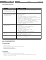
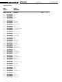
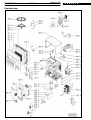
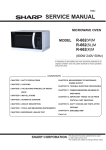
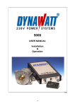
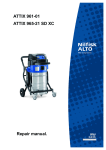
1
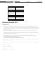
SERVICE
Whirlpool Europe
Customer Services
AVM 512
Service Manual
Microwave oven
AVM 512
Model
Version
AVM 512
8538 512 62291
Page
Introduction safety
2
Technical data
3
Text/Legend
4-8
Spare part list
9
Exploded view
10
Wiring diagram
11
This documentation is only intended for qualified technicians who are aware of the respective safety regulations.
Date: 11.11.1998
Subject to modification
Document-No.: 4812 714 12457
11.11.1998 / Page 2
Doc. No: 4812 714 12457
AVM 512
8538 512 62291
Whirlpool Europe
Customer Service
SERVICE
Introduction safety
INTRODUCTION
Before leaving the factory each oven is carefully checked.
It must, however, be installed and used correctly.
Despite all the steps taken to make the oven safe, the safety is dependent on the correct installation and the fact
the user understands how to use and maintain the oven.
The information in this section should be used as a reminder that the oven is safe and that anyone who uses it must
first read the instructions for use in order to be able to use the oven correctly and obtain best results.
SAFETY
To avoid injury to yourself and damage to the appliance always work to the following rules when servicing an oven.
Always disconnect the plug from the mains before starting work.
If there is no plug switch off the electric supply at the control box.
When you have finished servicing an oven before you reconnect it to the mains, make sure that:
- all the internal connections are correct
- the wires are insulated and not touching the door or the cabinet or anything sharp
- all the earth connections are electrically and mechanically sound
- do not modify or anyway interfere with the safety devices built-in to the oven
- make sure that each replacement part you use conforms to the manufacturer´s specifications
Do not start a repair if you have any doubt as to your ability to complete it.
CAUTION - MICROWAVE RADIATION
PERSONNEL SHOULD NOT BE EXPOSED TO THE MICROWAVE ENERGY WHICH MAY RADIATE FROM THE MAGNETRON,
WAVEGUIDE OR ANTENNA IF THEY ARE IMPROPERLY USED OR CONNECTED. ALL INPUT
AND OUTPUT MICROWAVE CONNECTIONS, WAVEGUIDES, FLANGES AND GASKETS MUST BE SECURE.
NEVER OPERATE THE DEVICE WITHOUT A MICROWAVE ENERGY ABSORBING LOAD ATTACHED.
NEVER LOOK INTO AN OPEN WAVEGUIDE OR ANTENNA WHILE THE DEVICE IS ENERGIZED.
NEVER OPERATE AN OVEN WITH CABINET OFF WITHOUT MEASURING THE MICROWAVE LEAKAGE
AROUND MAGNETRON AND VISIBLE MICROWAVE CONNECTIONS (WELDING JOINTS).
Do not operate the oven if the following conditions exist:
- the door does not close firmly against the door support because of the door being warped or the hinges damaged.
- The door trims or seals are damaged.
- If there is any visible damage to the oven.
- if the door does not close properly.
Avoid operating the oven if known components in the interlock system, oven door or microwave
generating assembly are known defective. They must be replaced.
WARNING - HIGH VOLTAGE
IT IS POSSIBLE TO COME IN CONTACT WITH LETHAL HIGH VOLTAGE WHEN WORKING WITH
HV TRANSFORMER, HV CAPACITOR AND MAGNETRON. THEREFORE NEVER TRY TO MEASURE
THE HIGH VOLTAGE. ALWAYS TAKE UTMOST CARE WHEN PERFORMING ELECTRIC
MEASUREMENTS INSIDE THE OVEN.
SERVICE
Whirlpool Europe
Customer Service
AVM 512
8538 512 62291
Technical data
Electrical
Voltage
Frequency
Power consumption
230
50
1350
V
Hz
W
850
2450
W
MHz
Power
Output power
Microwave frequency
Timer
Electronic
99 min. 99 sec.
10-level microwave power level
4-stage programmed cooking
11.11.1998 / Page 3
Doc. No: 4812 714 12457
11.11.1998 / Page 4
Doc. No: 4812 714 12457
AVM 512
8538 512 62291
Whirlpool Europe
Customer Service
SERVICE
Text/Legend
INSTALLATION REQUIREMENTS
GENERAL
The oven should be placed on a flat and stable surface
Place the oven away from high temperature and steam sources.
Clearance of at least 5cm (2”) on each side must be provided to allow adequate ventilation.
The microwave oven must be plugged directly to a 3-prong wall receptacle which is properly grounded.
The power source must be 220V 50Hz 8A single phase.
GROUNDING INSTRUCTIONS
IMPORTANT:
DISCONNECT POWER BEFORE SERVICING, RECONNECT ALL GROUNDING DEVICES.
All mechanical parts of this appliance capable of conducting electricity are grounded. In the event of an
electrical short circuit, grounding reduces the risk of electric shock. This appliance is equipped with a cord
having a grounding wire with a ground plug. The plug must be plugged into an outlet that is properly installed
and grounded.
WARNING:
IMPROPER USE OF THE GROUNDING PLUG MAY RESULT IN ELECTRICAL SHOCK.
If grounding wires, screws, straps, clips, nuts or washers used to complete a path to ground are removed for
service, they must be returned to their original positions and properly fastened.
GROUNDING SPECIFICATION:
Leakage current:
Ground path resistance:
0.5 mA max.
0.1 ohm max.
OPERATIONAL DESCRIPTION
The following describe the basic operation of the appliance. Please refer to the schematic diagram when
reading:
Food is placed inside the oven and the door is closed. “Start” button is not pressed:
Primary and secondary interlock switches are closed. Monitor switch is open. Door switch is closed. Relay 1
and relay 2 are both open.
When the timer is set for a certain cooking time, cook power is set and the “Start” button pressed:
Relay 1 is closed. AC power is supplied to the cavity lamp, fan motor and turntable motor. Depending on the
power level setting, AC power is supplied to the HV transformer through relay 2 with the duty cycle
corresponding to the power level setting. The display timer will start to count down.
When the timer counts to Zero:
Relay 1 and relay 2 will be and all AC power to the motor, lamp and HV transformer will be cut. The control
board buzzer will give a “beep” sound to give an OFF signal.
When the door is open during cooking:
Primary and secondary interlock switch are opened. Door switch is opened. The monitor switch is closed. All
AC power will be cut.
Pure microwave cooking:
10 power level settings are available for pure microwave cooking. This can be adjusted using the power switch
on the touch foil. Power level control is achieved by switching the magnetron ON and OFF periodically. The
oven works on 15 second cycle and the following indicate the correct ON/OFF timing.
SERVICE
Whirlpool Europe
Customer Service
Power setting
10(highest)
9
8
7
6
5
4
3
2
1 (lowest)
AVM 512
8538 512 62291
11.11.1998 / Page 5
Doc. No: 4812 714 12457
ON time
100%
approx 93%
approx 87%
approx 80%
approx 67%
approx 60%
approx 53%
approx 40%
approx 33%
approx 27%
MICROWAVE AND LEAKAGE TESTS
MICROWAVE TEST
The following is a simple test to check if the appliance is generating microwave energy. This test is not
intended to be an accurate test. An accurate measurement of output power must be performed under strict
control following the IEC standard. In field service, accurate measurement of output power is usually not
required and necessary.
Prepare a glass beaker with a diameter of approx. 190 mm round. with a max. 3 mm wall thickness.
Fill the beaker with exact 1 liter of cold water with an temperature of 10-12 ˚C measure the temperature
of the water before placing into the oven.
Start the oven for 1 min. on full power (only microwave) check the time by your writwatch after the
magnetron takes full power (Ampere meter).
The unit should be heated up 2-3 times before the test starts.
Check the water temperature under stirring the water and calculate the difference to the start temperature.
˚C x 70(multiplicator)=watt
Please take under consideration that always the measured power output is 15-20% lower than the rating plate
shows. 850 W = 720-680 W if the measured output is below this rate please repeat the measurement.
LEAKAGE TEST
TESTING EQUIPMENT
0.5l beaker.
Microwave tester of high quality.
11.11.1998 / Page 6
Doc. No: 4812 714 12457
AVM 512
8538 512 62291
Whirlpool Europe
Customer Service
SERVICE
TESTING PROCEDURE
Place 0.25l of water into the beaker and place it in the center of the oven.
Turn on the microwave oven by setting the unit on full power.
Hold the probe of the microwave tester to the surface of the oven and scan it at the rate of 2.5 cm per sec.
Test the following areas for microwave leakage:
- round and across the door glass and control panel.
- all ventilation openings.
The leakage should never exceed 5 mW/cm2.
Record all data.
OVEN LEAKAGE REPAIR
If leakage figure is found above 5 mW/cm2.
The unit has to be set out of function, until the unit is repaired and finally saefty tested.
Service engineer should notify the Service Management immediately.
TROUBLE SHOOTING GUIDE
CAUTION AND IMPORTANT
Before disassembling the oven, the oven power must be turned off. Remove the power plug of the oven from
the outlet and wait for at least 3 minutes.
When disassembling, service personnel should remove their watches and metal chains from their hands.
Never touch the high voltage components and wire.
Before checking or replacing, discharge the high voltage capacitor to oven chassis grounded with an insulated
wire. Make sure that the wire is grounded to chassis side before short circuiting the capacitor terminal.
Do not measure high voltage with a common voltmeter.
SERVICE
Whirlpool Europe
Customer Service
AVM 512
8538 512 62291
11.11.1998 / Page 7
Doc. No: 4812 714 12457
QUICK SERVICE REFERENCES
PROBLEM
Cavity lamp does not light, but
other electrical components
(e.g. turntable) are working.
Cavity lamp does not light, all
other electrical components
also do not work.
Oven seems working, food
does not cook
Oven cooks for a short while
and stop.
Turntable does not turn.
User circuit breaker activates.
POINTS TO CHECK
Lamp burnt.
Bad contact between lamp and lamp socket.
Power plug not in good connection with the socket.
No power supply.
Fuse blown.
Bad contact between fuse and fuse holder/clip.
Loose door hinge, door poorly adjusted, interlock poorly
adjusted; causing fuse to be blown.
Short circuit within electrical circuit.Lamp filament short,
HV transformer short, all causing fuse blown.
Bad contact in contacts or terminals of timer switch,
primary and secondary interlock switch.
HV diode break down.
Defective magnetron (filament broken, filament short to
ground etc.).
Ground wire of HV transformer broken.
Filament wire short to ground.
Filament wire broken.
Bad contact in magnetron terminals.
Defective control boards.
HV diode break down, giving a hum noise.
Cooling fan jammed.
Cooling fan motor open circuit.
Defective cooling fan control relay.
Defective turntable motor.
Turntable shaft deformed.
High leakage in electrical components (mostly motor).
MAJOR COMPONENT TESTS
HV TRANSFORMER
Remove lead wire.
Measure the resistance of the winding using an ohm meter
Primary winding 3 ohm (approx.)
Secondary winding 100 ohm (approx.)
Filament winding 0 ohm (approx.)
HV CAPACITOR
Remove lead wire
Measure the resistance using an ohm meter set to R*1000
Terminal to terminal should momentary indicates several ohms but gradually increases to infinite.
Terminal to case should show infinite.
11.11.1998 / Page 8
Doc. No: 4812 714 12457
AVM 512
8538 512 62291
Whirlpool Europe
Customer Service
SERVICE
HV DIODE
Remove lead wire.
Measure forward resistance, normal diode show continuity.
Measure reverse resistance, normal diode show infinite resistance.
MAGNETRON
Remove lead wire.
Install the magnetron gasket in the correct position. Check that the gasket is in good condition.
Measure the resistance of the filament terminals. Normal magnetron should be less than 1 ohm.
Measure the resistance between the filament terminal to chassis. Normal magnetron should be infinite.
INTERLOCK SWITCH SYSTEM
IMPORTANT: The installation of the interlock and monitor switches is required by Federal regulations.
Oven door
status
Open
Close
Primary
switch
Open
Close
Secondary
switch
Open
Close
Monitor
switch
Close
Open
The interlock and monitor switches positions are not service adjustable. If the screws on the hinges of the
oven door are loosen, the door may not be in a correct position. In this case, the interlock switches cannot be
operated by the latch pins of the door when the door is shut. To repair the door, remount the door and fasten
the screws on the door hinges.
The monitor switch is provided to monitor the operation of the primary interlock switch. If the primary switch
fails to operate when the door is open, the monitor switch will form a short circuit across the supply and the
fuse in the oven will blow. Electric arc may form across the switch contacts of the primary interlock switch,
the secondary switch and the monitor switch. The switches may then be damaged. If the fuse is blown due
to the failure of the primary interlock, repair the failed mechanical parts and replace all the interlock switches.
IMPORTANT
After replacement of any part of the interlock and monitor circuit:
Check if the microswitches are turned ON and OFF by the latches as specified in the table above.
Apply sealant to the screws and nuts of the door hinges.
Check microwave leakage.
Check if the oven will turn off instantly when the door button is pushed to the position where the door latches
leave the interlock switches.
SERVICE
Whirlpool Europe
Customer Service
AVM512
8538 512 62291
11.11.1998 / Page 9
Doc. No: 4812 714 12457
Spare part list
Model
Service No.
Version
AVM 512
853851262291
853851262291
Pos. No. 12NC Code
Description
002 0
002 2
002 3
002 4
011 0
4819 902 00561
4819 902 00568
4819 902 00571
4819 902 00569
4819 902 00694
Lid
Plate
Pin
Bushing
Foot
011 1
040 0
040 1
121 0
121 1
4819 902 00566
4819 902 00445
4819 902 00444
4819 902 00326
4819 902 00599
Cap
Hinge,upper
Hinge,lower
Door,inner
Door frame inner
130 0
130 9
131 0
131 1
131 2
4819 902 00579
4819 902 00597
4819 902 00596
4819 902 00595
4819 902 00594
Holder
Hook connector
Lockingmechn. upper
Lockingmechn. lower
Pivot door pin
141 0
142 0
143 0
255 0
264 0
4819 902 00484
4819 450 58454
4819 459 48923
4819 902 00654
4819 902 00529
Oven glass outer
Glass inner (PE plate)
Door frame
Turntable glass
Ring turn table
264 1
264 2
320 0
321 0
332 0
4819 902 00582
4819 902 00528
4819 902 00683
4819 902 00644
4819 902 00557
Wheel
Shaft
Control panel
Display glass
Button door
404 0
406 0
406 3
412 0
420 0
4819 902 00614
4819 902 00695
4819 902 00567
4819 902 00556
4819 902 00583
Magnetron
Motor turn table
Gasket
Transformer HV
Capacitor HV 0.95UF
421 0
426 0
426 1
440 0
443 0
4819 902 00679
4819 218 38038
4819 902 00574
4819 902 00696
4819 902 00592
Filter
Diode HV
Diode double way
Propeller,motor
Fan wheel
443 1
490 0
490 4
490 5
490 6
4819 902 00591
4819 902 00298
4819 902 00563
4819 902 00604
4819 404 79411
Support fan
Cable,mains SAA Plug
Clip wire sadle
Strain relief
Bracket for cable
500 0
561 0
562 0
620 0
632 0
4819 214 78684
4819 902 00586
4819 902 00636
4819 902 00682
4819 902 00609
Control unit
Thermostat magnetron
Thermostat
Switch plate
Switch security
632 1
633 0
651 0
743 0
900 5
4819 902 00447
4819 902 00611
4819 134 28051
4819 902 00575
4819 902 00585
Lever
Switch
Lamp
Air guide
Holder filter board
904 0
910 9
930 0
930 1
930 3
4819 902 00589
4819 902 00565
4819 902 00581
4819 902 00598
4819 902 00601
Sleeve
Pin
Spring,tension
Spring
Spring,compres.
from
to
11.11.1998 / Page 10
Doc. No: 4812 714 12457
Exploded view
AVM 512
8538 512 62291
Whirlpool Europe
Customer Service
SERVICE
SERVICE
Wiring diagram
Whirlpool Europe
Customer Service
AVM 512
8538 512 62291
11.11.1998 / Page 11
Doc. No: 4812 714 12457