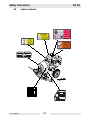
1
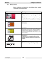
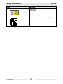
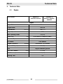
www.wackergroup.com 0160360en 0107 Pump PDT 2 PDI 2 PDT 3 PDI 3 OPERATOR’S MANUAL 0 1 6 0 3 6 0 E N 001 PD 2/3 Table of Contents 1. Foreword 3 2. Emission Control System Information 4 3. Safety Information 4. 5. 15 3.1 Laws Pertaining to Spark Arresters .................................................... 15 3.2 Operating Safety ................................................................................ 16 3.3 Operator Safety while using Internal Combustion Engines ................ 17 3.4 Service Safety .................................................................................... 17 3.5 Label Locations ................................................................................ 18 3.6 Safety Labels ...................................................................................... 19 Technical Data 21 4.1 Engine ................................................................................................ 21 4.2 Pump .................................................................................................. 22 4.3 Sound Measurements ........................................................................ 22 Operation 23 5.1 Application .......................................................................................... 23 5.2 Recommended Fuel ........................................................................... 23 5.3 Priming Pump ..................................................................................... 24 5.4 Before Starting ................................................................................... 24 5.5 To Start ............................................................................................... 25 5.6 To Stop ............................................................................................... 25 5.7 Operation ............................................................................................ 26 5.8 Accessories ........................................................................................ 26 5.9 Hoses and Clamps ............................................................................. 27 wc_bo0160360en_001TOC.fm 1 Table of Contents 6. PD 2/3 Maintenance 6.1 6.2 6.3 6.4 6.5 6.6 6.7 6.8 6.9 6.10 28 Periodic Maintenance Schedule ..........................................................28 Changing Engine Oil ...........................................................................29 Cleaning Fuel Strainer .........................................................................29 Servicing Air Cleaner ...........................................................................30 Spark Plug ...........................................................................................31 Gear Case ...........................................................................................32 Connecting Rod Bearing .....................................................................33 Cleaning Pump ....................................................................................33 Storage ................................................................................................34 Troubleshooting ...................................................................................35 wc_bo0160360en_001TOC.fm 2 CALIFORNIA Proposition 65 Warning: WARNING 1. Engine exhaust, some of its constituents, and certain vehicle components, contain or emit chemicals known to the State of California to cause cancer and birth defects or other reproductive harm. Foreword This manual provides information and procedures to safely operate and maintain this Wacker model. For your own safety and protection from injury, carefully read, understand and observe the safety instructions described in this manual. Keep this manual or a copy of it with the machine. If you lose this manual or need an additional copy, please contact Wacker Corporation. This machine is built with user safety in mind; however, it can present hazards if improperly operated and serviced. Follow operating instructions carefully! If you have questions about operating or servicing this equipment, please contact Wacker Corporation. The information contained in this manual was based on machines in production at the time of publication. Wacker Corporation reserves the right to change any portion of this information without notice. All rights, especially copying and distribution rights, are reserved. Copyright 2007 by Wacker Corporation. No part of this publication may be reproduced in any form or by any means, electronic or mechanical, including photocopying, without express written permission from Wacker Corporation. Any type of reproduction or distribution not authorized by Wacker Corporation represents an infringement of valid copyrights and will be prosecuted. We expressly reserve the right to make technical modifications, even without due notice, which aim at improving our machines or their safety standards. wc_tx000001gb.fm 3 Emission Control System Information 2. Emission Control System Information Source of Emissions The combustion process produces carbon monoxide, oxides of nitrogen, and hydrocarbons. Control of hydrocarbons and oxides of nitrogen is very important because, under certain conditions, they react to form photochemical smog when subjected to sunlight. Carbon monoxide does not react in the same way, but it is toxic. Wacker utilizes lean carburetor settings and other systems to reduce the emissions of carbon monoxide, oxides of nitrogen, and hydrocarbons. The U.S. and California Clean Air Acts EPA and California regulations require all manufacturers to furnish written instructions describing the operation and maintenance of emission control systems. The following instructions and procedures must be followed in order to keep the emissions from your Wacker engine within the emissions standards. Tampering and Altering Tampering with or altering the emission control system may increase emissions beyond the legal limit. Among those acts that constitute tampering are: •Removal or alteration of any part of the intake, fuel, or exhaust systems. •Altering or defeating the speed-adjusting mechanism to cause the engine to operate outside its design parameters. Problems That May Affect Emissions If you are aware of any of the following symptoms, have your engine inspected and repaired by your servicing dealer. •Hard starting or stalling after starting. •Rough idle. •Misfiring or backfiring under load. •Afterburning (backfiring). •Black exhaust smoke or high fuel consumption. wc_tx000239gb.fm 4 Emission Control System Information Replacement Parts The emission control systems on your Wacker engine were designed, built, and certified to conform with EPA and California emissions regulations. We recommend the use of genuine Wacker parts whenever you have maintenance done. These original-design replacement parts are manufactured to the same standards as the original parts, so you can be confident of their performance. The use of replacement parts that are not of the original design and quality may impair the effectiveness of your emission control system. A manufacturer of an aftermarket part assumes the responsibility that the part will not adversely affect emission performance. The manufacturer or rebuilder of the part must certify that use of the part will not result in a failure of the engine to comply with emission regulations. Maintenance Follow the maintenance schedule. Remember that this schedule is based on the assumption that your machine will be used for its designed purpose. Sustained high-load or high-temperature operation, or use in unusually wet or dusty conditions, will require more frequent service. OXYGENATED FUELS Some conventional gasolines are being blended with alcohol or an ether compound. These gasolines are collectively referred to as oxygenated fuels. To meet clean air standards, some areas of the United States and Canada use oxygenated fuels to help reduce emissions. If you use an oxygenated fuel, be sure it is unleaded and meets the minimum octane rating requirement. Before using an oxygenated fuel, try to confirm the fuel’s contents. Some States / Provinces require this information to be posted on the pump. The following are EPA-approved percentages of oxygenates: ETHANOL - (ethyl or grain alcohol) 10% by volume. You may use gasoline containing up to 10% ethanol by volume. Gasoline containing ethanol may be marketed under the name “Gasohol”. MTBE - (methyl tertiary butyl ether) 15% by volume. You may use gasoline containing up to 15% MTBE by volume. wc_tx000239gb.fm 5 Emission Control System Information METHANOL - (methyl or wood alcohol) 5% by volume. You may use gasoline containing up to 5% methanol by volume, as long as it contains cosolvents and corrosion inhibitors to protect the fuel system. Gasoline containing more than 5% methanol by volume may cause starting and/or performance problems. It may also damage metal, rubber, and plastic parts of your fuel system. If you notice any undesirable operating symptoms, try another service station, or switch to another brand of gasoline. Fuel system damage or performance problems resulting from the use of an oxygenated fuel containing more than the percentages of oxygenates mentioned above are not covered under warranty. wc_tx000239gb.fm 6 Emission Control System Information EMISSIONS COMPONENT DEFECT WARRANTY COVERAGE This emission warranty is applicable in all States, except the State of California. Wacker Corporation, N92 W15000 Anthony Avenue, Menomonee Falls, WI 53051-1504, (herein "Wacker") warrant(s) to the initial retail purchaser and each subsequent owner, that this non-road engine (herein "engine") has been designed, built, and equipped to conform at the time of initial sale to all applicable regulations of the U.S. Environmental Protection Agency (EPA), and that the engine is free of defects in materials and workmanship which would cause this engine to fail to conform with EPA regulations during its warranty period. For the components listed under PARTS COVERED, the service dealer authorized by Wacker will, at no cost to you, make the necessary diagnosis, repair, or replacement necessary to ensure that the engine complies with applicable U.S. EPA regulations. EMISSISON COMPONENT DEFECT WARRANTY PERIOD The warranty period for this engine begins on the date of sale to the initial purchaser and continues for a period of 2 years. wc_tx000239gb.fm 7 Emission Control System Information PARTS COVERED Listed below are the parts covered by the Emission Components Defect Warranty. Some of the parts listed below may require scheduled maintenance and are warranted up to the first scheduled replacement point for that part. (1) Fuel Metering System (i) Carburetor and internal parts (and/or pressure regulator or fuel injection system). (ii) Air/fuel ratio feedback and control system, if applicable. (iii) Cold start enrichment system, if applicable. (iv) Regulator assembly (gaseous fuel, if applicable) . (2) Air Induction System (i) Intake manifold, if applicable. (ii) Air filter. (3) Ignition System (i) Spark plugs. (ii) Magneto or electronic ignition system. (iii) Spark advance/retard system, if applicable. (4) Exhaust manifold, if applicable (5) Miscellaneous Items Used in Above Systems (i) Electronic controls, if applicable. (ii) Hoses, belts, connectors, and assemblies. (iii) Filter lock assembly (gaseous fuel, if applicable). wc_tx000239gb.fm 8 Emission Control System Information OBTAINING WARRANTY SERVICE To obtain warranty service, take your engine to the nearest authorized Wacker service dealer. Bring your sales receipts indicating date of purchase for this engine. The service dealer authorized by Wacker will perform the necessary repairs or adjustments within a reasonable amount of time and furnish you with a copy of the repair order. All parts and accessories replaced under this warranty become the property of Wacker. WHAT IS NOT COVERED • Conditions resulting from tampering, misuse, improper adjustment (unless they were made by the service dealer authorized by Wacker during a warranty repair), alteration, accident, failure to use the recommended fuel and oil, or not performing required maintenance services. • The replacement parts used for required maintenance services. • Consequential damages such as loss of time, inconvenience, loss of use of the engine or equipment, etc. • Diagnosis and inspection charges that do not result in warrantyeligible service being performed. • Any non-authorized replacement part, or malfunction of authorized parts due to use of non-authorized parts. OWNER'S WARRANTY RESPONSIBILITIES As the engine owner, you are responsible for the performance of the required maintenance listed in your owner's manual. Wacker recommends that you retain all receipts covering maintenance on your engine, but Wacker cannot deny warranty solely for the lack of receipts or for your failure to ensure the performance of all scheduled maintenance. As the engine owner, you should however be aware that Wacker may deny warranty coverage if your engine or a part has failed due to abuse, neglect, improper maintenance or unapproved modifications. You are responsible for presenting your engine to the nearest service dealer authorized by Wacker when a problem exists. If you have any questions regarding your warranty rights and responsibilities, you should contact the WACKER CORPORATION Product Support Department (U.S.A. 1-800-770-0957, Canada 1-877977-0775) for the information. wc_tx000239gb.fm 9 Emission Control System Information THINGS YOU SHOULD KNOW ABOUT THE EMISSION CONTROL SYSTEM WARRANTY: MAINTENANCE AND REPAIRS You are responsible for the proper maintenance of the engine. You should keep all receipts and maintenance records covering the performance of regular maintenance in the event questions arise. These receipts and maintenance records should be transferred to each subsequent owner of the engine. Wacker reserves the right to deny warranty coverage if the engine has not been properly maintained. Warranty claims will not be denied, however, solely because of the lack of required maintenance or failure to keep maintenance records. MAINTENANCE, REPLACEMENT OR REPAIR OF EMISSION CONTROL DEVICES AND SYSTEMS MAY BE PERFORMED BY ANY REPAIR ESTABLISHMENT OR INDIVIDUAL; HOWEVER, WARRANTY REPAIRS MUST BE PERFORMED BY A SERVICE DEALER AUTHORIZED BY WACKER. THE USE OF PARTS THAT ARE NOT EQUIVALENT IN PERFORMANCE AND DURABILITY TO AUTHORIZED PARTS MAY IMPAIR THE EFFECTIVENESS OF THE EMISSION CONTROL SYSTEM AND MAY HAVE A BEARING ON THE OUTCOME OF A WARRANTY CLAIM. If other than the parts authorized by Wacker are used for maintenance replacements or for the repair of components affecting emission control, you should assure yourself that such parts are warranted by their manufacturer to be equivalent to the parts authorized by Wacker in their performance and durability. HOW TO MAKE A CLAIM All repair qualifying under this limited warranty must be performed by a service dealer authorized by Wacker. In the event that any emissionrelated part is found to be defective during the warranty period, you shall notify WACKER CORPORATION Product Support Department (U.S.A. 1-800-770-0957, Canada 1-877-977-0775) and you will be advised of the appropriate warranty service dealer or service providers where the warranty repair can be performed. CALIFORNIA EMISSION CONTROL WARRANTY STATEMENT YOUR WARRANTY RIGHTS AND OBLIGATIONS The California Air Resources Board and Wacker Corporation (herein “Wacker”) are pleased to explain the emissions control system warranty on your small off-road engine. In California, new small offroad engines must be designed, built and equipped to meet the State's stringent anti-smog standards. Wacker Corporation must warrant the emissions control system on your engine for the periods of time listed below provided there has been no abuse, neglect or improper maintenance of your engine. wc_tx000239gb.fm 10 Emission Control System Information Your emission control system may include parts such as the carburetor or fuel-injection system, fuel lines and the ignition system. Also included may be hoses, clamps, connectors and other associated components. Where a warrantable condition exists, a Wacker authorized service center will repair your Wacker engine at no cost to you including diagnosis, parts and labor. MANUFACTURER'S WARRANTY COVERAGE: The emissions control system is warranted for two years. If any emissions-related part on your engine is defective, the part will be repaired or replaced by Wacker. OWNER'S WARRANTY RESPONSIBILITIES: As the Wacker engine owner, you are responsible for the performance of the required maintenance listed in your owner's manual. Wacker recommends that you retain all receipts covering maintenance on your Wacker engine, but Wacker cannot deny warranty solely for the lack of receipts. As the Wacker engine owner, you should however be aware that Wacker may deny you warranty coverage if your Wacker engine or a part has failed due to abuse, neglect, improper maintenance or unapproved modifications. You are responsible for presenting your Wacker engine to a Wacker dealer or service center as soon as a problem exists. The warranty repairs should be completed in a reasonable amount of time, not to exceed 30 days. If you have any questions regarding your warranty rights and responsibilities, you should contact your local Wacker equipment dealer, service center or the WACKER CORPORATION Product Support Department (U.S.A. 1-800-770-0957, Canada 1-877-9770775) for the information. wc_tx000239gb.fm 11 Emission Control System Information GENERAL EMISSIONS WARRANTY COVERAGE - California Only Wacker warrants to the ultimate purchaser and each subsequent purchaser that this small off-road engine (1) has been designed, built and equipped so as to conform with all applicable regulations; and (2) is free from defects in materials and workmanship that cause the failure of a warranted part to conform with those regulations as may be applicable to the terms and conditions stated below. A. The warranty period begins on the date the engine is delivered to an ultimate purchaser or first placed into service. The warranty period is two years. B. Subject to certain conditions and exclusions as stated below, the warranty on emissions related parts is as follows: wc_tx000239gb.fm 1) Any warranted part that is not scheduled for replacement as required maintenance in your owner’s manual is warranted for the warranty period stated above. If the part fails during the period of warranty coverage, the part will be repaired or replaced by Wacker according to subsection (4) below. Any such part repaired or replaced under warranty will be warranted for the remainder of the period. 2) Any warranted part that is scheduled only for regular inspection in your owner’s manual is warranted for the warranty period stated above. Any such part repaired or replaced under warranty will be warranted for the remaining warranty period. 3) Any warranted part that is scheduled for replacement as required maintenance in your owner’s manual is warranted for the period of time before the first scheduled replacement date for that part. If the part fails before the first scheduled replacement, that part will be repaired or replaced by Wacker according to subsection (4) below. Any such part repaired or replaced under warranty will be warranted for the remainder of the period prior to the first scheduled replacement point for the part. 4) Repair or replacement of any warranted part under the warranty provisions herein must be performed at a warranty station at no charge to the owner. 5) Notwithstanding the provisions herein, warranty services or repair will be provided at all of our distribution centers that are franchised to service the subject engines. 6) The owner must not be charged for diagnostic labor that leads to the determination that a warranted part is in fact defective, provided that such diagnostic work is performed at a warranty station. 12 Emission Control System Information 7) Wacker is liable for damages to other engine components proximately caused by a failure under warranty of any warranted part. 8) Throughout the engine warranty period stated above, Wacker will maintain a supply of warranted parts sufficient to meet the expected demand for such parts. 9) Any replacement part may be used in the performance of any warranty maintenance or repairs and must be provided without charge to the owner. Such use will not reduce the warranty obligations of Wacker. 10) Add-on or modified parts that are not exempted by the Air Resources Board may not be used. The use of any nonexempted add-on or modified parts by the ultimate purchaser will be grounds for disallowing a warranty claim. Wacker will not be liable to warrant failures of warranted parts caused by the use of a non-exempted add-on or a modified part. wc_tx000239gb.fm 13 Emission Control System Information C. Warranted Parts: The repair or replacement of any warranted part otherwise eligible for warranty coverage may be excluded from such warranty coverage if Wacker demonstrates that the engine has been abused, neglected, or improperly maintained, and that such abuse, neglect, or improper maintenance was the direct cause of the need for repair or replacement of the part. That notwithstanding, any adjustment of a component that has a factory installed, and properly operating, adjustment limiting device is still eligible for warranty coverage. The following emissions warranty parts list are covered. 1) Fuel Metering System i) Carburetor and internal parts (and/or pressure regulator or fuel injection system). ii) Air/fuel ratio feedback and control system, if applicable. iii) Cold start enrichment system, if applicable. iv) Regulator assembly (gaseous fuel, if applicable) 2) Air Induction System i) Intake manifold, if applicable. ii) Air filter 3) Ignition System i) Spark plugs ii) Magneto or electronic ignition system iii) Spark advance/retard system, if applicable 4) Exhaust manifold, if applicable 5) Evaporation System i) Fuel line ii) Fuel line fittings wc_tx000239gb.fm 14 PD 2/3 3. Safety Information Safety Information This manual contains DANGER, WARNING, CAUTION, and NOTE callouts which must be followed to reduce the possibility of personal injury, damage to the equipment, or improper service. This is the safety alert symbol. It is used to alert you to potential personal injury hazards. Obey all safety messages that follow this symbol to avoid possible injury or death. DANGER indicates a hazardous situation which, if not avoided, will result in death or serious injury. DANGER WARNING indicates a hazardous situation which, if not avoided, could result in death or serious injury. WARNING CAUTION indicates a hazardous situation which, if not avoided, could result in minor or moderate injury. CAUTION CAUTION: Used without the safety alert symbol, CAUTION indicates a potentially hazardous situation which, if not avoided, may result in property damage. Note: Contains additional information important to a procedure. 3.1 Laws Pertaining to Spark Arresters Notice: State Health Safety Codes and Public Resources Codes specify that in certain locations spark arresters be used on internal combustion engines that use hydrocarbon fuels. A spark arrester is a device designed to prevent accidental discharge of sparks or flames from the engine exhaust. Spark arresters are qualified and rated by the United States Forest Service for this purpose. In order to comply with local laws regarding spark arresters, consult the engine distributor or the local Health and Safety Administrator. wc_si000144gb.fm 15 Safety Information 3.2 PD 2/3 Operating Safety DANGER Internal combustion engines present special hazards during operation and fueling. Read and follow the warning instructions in the engine owner’s manual and the safety guidelines below. Failure to follow the warnings and safety guidelines could result in severe injury or death. 3.2.1 NEVER allow anyone to operate this equipment without proper training. People operating this equipment must be familiar with the risks and hazards associated with it. 3.2.2 NEVER touch the engine or muffler while the engine is on or immediately after it has been turned off. These areas get hot and may cause burns. 3.2.3 NEVER use accessories or attachments that are not recommended by Wacker. Damage to equipment and injury to the user may result. 3.2.4 NEVER pump volatile, flammable or low flash point fluids. These fluids could ignite or explode. 3.2.5 NEVER pump corrosive chemicals or water containing toxic substances. These fluids could create serious health and environmental hazards. Contact local authorities for assistance. 3.2.6 ALWAYS read, understand, and follow procedures in the Operator’s Manual before attempting to operate the equipment. 3.2.7 ALWAYS be sure operator is familiar with proper safety precautions and operation techniques before using machine. 3.2.8 ALWAYS be sure the machine is on a firm, level surface and will not tip, roll, slide, or fall while operating. 3.2.9 ALWAYS close fuel valve on engines equipped with one when machine is not being operated. 3.2.10 ALWAYS store the equipment properly when it is not being used. Equipment should be stored in a clean, dry location out of the reach of children. wc_si000144gb.fm 16 PD 2/3 3.3 Safety Information Operator Safety while using Internal Combustion Engines WARNING 3.4 3.3.1 DO NOT smoke while operating the machine. 3.3.2 DO NOT smoke when refueling the engine. 3.3.3 DO NOT refuel a hot or running engine. 3.3.4 DO NOT refuel the engine near an open flame. 3.3.5 DO NOT spill fuel when refueling the engine. 3.3.6 DO NOT run the engine near open flames. 3.3.7 ALWAYS refill the fuel tank in a well-ventilated area. 3.3.8 ALWAYS replace the fuel tank cap after refueling. Service Safety WARNING wc_si000144gb.fm Poorly maintained equipment can become a safety hazard! In order for the equipment to operate safely and properly over a long period of time, periodic maintenance and occasional repairs are necessary. Poorly maintained equipment can become a safety hazard! In order for the equipment to operate safely and properly over a long period of time, periodic maintenance and occasional repairs are necessary. 3.4.1 DO NOT attempt to clean or service the machine while it is running. Rotating parts can cause severe injury. 3.4.2 DO NOT crank a flooded engine with the spark plug removed on gasoline-powered engines. Fuel trapped in the cylinder will squirt out the spark plug opening. 3.4.3 DO NOT test for spark on gasoline-powered engines if the engine is flooded or the smell of gasoline is present. A stray spark could ignite the fumes. 3.4.4 DO NOT use gasoline or other types of fuels or flammable solvents to clean parts, especially in enclosed areas. Fumes from fuels and solvents can become explosive. 3.4.5 ALWAYS operate the machine with all safety devices and guards in place and in working order. 3.4.6 ALWAYS keep the area around the muffler free of debris such as leaves, paper, cartons, etc. A hot muffler could ignite the debris and start a fire. 3.4.7 ALWAYS replace worn or damaged components with spare parts designed and recommended by Wacker Corporation. 3.4.8 ALWAYS disconnect the spark plug on machines equipped with gasoline engines, before servicing, to avoid accidental start-up. 17 Safety Information Label Locations CAUTION VORSICHT GREASE CONNECTING ROD BEARING MONTHLY PLEUELLAGER JEDEN MONAT SCHMIEREN PRECAUCION PRECAUTION ENGRASE RODAMIENTO DE LA BIELA MENSUALMENTE GRAISSER ROULEMENT DE LA BIELLE TOUS LES MOIS 30744 3.5 PD 2/3 WARNING DO NOT OPERATE WITHOUT SAFETY GUARDS. READ AND UNDERSTAND INSTRUCTION BOOK. WARNUNG NICHT OHNE SCHUTZVORRICHTUNG BETREIBEN. BEDIENUNGSANWEISUNG GENAU DURCHLESEN. ADVERTENCIA AVERTISSEMENT NE PAS OPERER SANS DEFLECTEUR PROTECTIF. LIRE ET COMPRENDRE LES INSTRUCTIONS DE SERVICE. wc_si000144gb.fm 18 117431 NO OPERE SIN LOS DISPOSITIVOS DE SEGURIDAD. LEA Y ENTIENDA PRIMERO LAS INSTRUCCIONES. PD 2/3 Safety Information 3.6 Safety Labels Wacker machines use international pictorial labels where needed. These labels are described below: Label Meaning DANGER! Engines emit carbon monoxide; operate only in well-ventilated area. Read the Operator’s Manual. No sparks, flames, or burning objects near the machine. Shut off the engine before refueling. WARNING! Hot surface! CAUTION! Read and understand the supplied Operator’s Manuals before operating this machine. Failure to do so increases the risk of injury to yourself or others. WARNING! Pinch point! Do not operate without safety guards. Read and understand the operator’s manual. WARNING DO NOT OPERATE WITHOUT SAFETY GUARDS. READ AND UNDERSTAND INSTRUCTION BOOK. WARNUNG NICHT OHNE SCHUTZVORRICHTUNG BETREIBEN. BEDIENUNGSANWEISUNG GENAU DURCHLESEN. ADVERTENCIA AVERTISSEMENT NE PAS OPERER SANS DEFLECTEUR PROTECTIF. LIRE ET COMPRENDRE LES INSTRUCTIONS DE SERVICE. VORSICHT GREASE CONNECTING ROD BEARING MONTHLY PLEUELLAGER JEDEN MONAT SCHMIEREN PRECAUCION PRECAUTION ENGRASE RODAMIENTO DE LA BIELA MENSUALMENTE GRAISSER ROULEMENT DE LA BIELLE TOUS LES MOIS wc_si000144gb.fm CAUTION! Grease connecting rod bearing monthly. 30744 CAUTION 117431 NO OPERE SIN LOS DISPOSITIVOS DE SEGURIDAD. LEA Y ENTIENDA PRIMERO LAS INSTRUCCIONES. 19 Safety Information Label PD 2/3 Meaning CAUTION! Lifting point Guaranteed sound power level in dB(A) wc_si000144gb.fm 20 PD 2/3 4. Technical Data Technical Data 4.1 Engine Item Number: PDI/PDT 2 0009489, 0009494 PDI/PDT 3 0009491, 0009492, 0009495 Engine Engine Make Wacker Engine Model WM 130 Displacement cm3 (in3) Engine Speed rpm Max. Operating Power Spark Plug Electrode Gap Air Cleaner 126 (7.7) 2800 3.2 (4.3) kW (Hp) NGK BR6HS (Champion RL86C) type 0.6–0.7 (0.024–0.028) mm (in.) Dual element type Engine Lubrication oil grade SAE10W30 - SE or higher Engine Oil Capacity ml (oz.) 600 (20) Fuel Fuel Tank Capacity Fuel Consumption Running Time wc_td000144gb.fm Regular unleaded gasoline type l (qts.) 2.7 (2.9) l (qts.)/hr. 1.1 (1.2) 2.5 hr. 21 Technical Data 4.2 PD 2/3 Pump Item Number: PDI/PDT 2 0009489, 0009494 PDI/PDT 3 0009491, 0009492, 0009495 Pump Dimensions (L x W x H) mm (in.) 1010 x 630 x 570 (40 x 25 x 22.5) 1010 x 745 x 605 (40 x 29.3 x 24) 52 (114) 61 (133) Operating Weight kg (lbs.) *Max. Suction Lift m (ft.) 7.5 (25) Max. Discharge Head m (ft.) 7.5 (25) Max. Flow Rate l/m (gpm) Gear Case Lubrication oil grade ml (oz.) 189 (50) 333 (88) SAE 80W-90 532 (18) Suction / Discharge Dia. mm (in.) 50 (2) 75 (3) Maximum Solid Size mm (in.) 32 (1.25) 45 (1.75) * Based on pump operating at sea level. Maximum suction lift will be less at higher altitudes. 4.3 Sound Measurements The required sound specification, Paragraph 1.7.4.f of 89/392/EEC Machinery Directive, is: • the guaranteed sound power level (LWA) = 96 dB(A). • the sound pressure level at operator’s location (LpA): PDT 2 = 78.8, PDT 3 = 82. These sound values were determined according to ISO 3744 for the sound power level (LWA) and ISO 6081 for the sound pressure level (LpA) at the operator’s location. wc_td000144gb.fm 22 PD 2/3 5. Operation Operation 5.1 Application This pump is intended for removing clean water or water containing a large amount of debris and suspended solids. The model PD 2 can pump water containing solids up to 30 mm (1.25 in.) diameter. The model PD 3 can pump water containing solids up to 45 mm (1.75 in.) in diameter. Diaphragm pumps are ideal for pumping mud, slurries and seepage. Typical applications include dewatering of trenches, sewers, pipelines, septic tanks, holding tanks, farm ponds, fields and excavations where a large amount of solids may be present in the water. 5.2 Recommended Fuel The engine requires regular grade unleaded gasoline. Use only fresh, clean gasoline. Gasoline containing water or dirt will damage fuel system. Consult engine Owner’s Manual for complete fuel specifications. wc_tx000405gb.fm 23 Operation 5.3 PD 2/3 Priming Pump See Graphic: wc_gr001064 Diaphragm pumps are self priming and seldom need to have water added to them before starting. However, if the pump has not been used for several weeks and the rubber valves inside it are dry, adding water through the surge chamber (f) will help the valves seal and shorten the amount of time required for the pump to prime. f e b a a b c b d 5.4 w c _ g r0 0 1 0 6 4 Before Starting See Graphic: wc_gr001064 5.4.1 Read safety instructions at the beginning of manual. 5.4.2 Place pump as near to water as possible, on a firm, flat, level surface. 5.4.3 Check that hoses are securely attached to pump. Suction hose (c) must not have any air leaks. Check that all hose clamps (b) and couplings (a) are tight. Check that cap on surge chamber (f) is tight. 5.4.4 Check that discharge hose (e) is not blocked. Lay hose out as straight as possible. Remove any twists or sharp bends from hose which may block the flow of water. Note: Operating the pump with any part of the discharge line positioned higher than 7.5 m (25 ft.) above the pump can cause backflow into the pump and damage pump components. 5.4.5 Make sure suction strainer (d) is clean and securely attached to end of hose. The strainer is designed to protect the pump by preventing large objects from being pulled into the pump. Position strainer so it will remain under water as water level drops. 5.4.6 wc_tx000405gb.fm Check fuel level, engine oil level, and condition of air cleaner. 24 PD 2/3 5.5 Operation To Start See Graphic: wc_gr000655 5.5.1 Open fuel valve by moving lever down (a1). Note: If engine is cold, move choke lever to close position (d2). If engine is hot, set choke to open position (d1). 5.5.2 Turn engine switch to “ON” (b2). 5.5.3 Open throttle by moving it slightly to left (c2). 5.5.4 Pull starter rope (e). Note: If the oil level in the engine is low, the engine will not start. If this happens, add oil to engine. 5.5.5 Open choke as engine warms (d1). 5.5.6 Open throttle fully to operate (c1). b2 a2 c3 c1 c2 b1 a1 d1 d2 e wc_gr000655 5.6 To Stop See Graphic: wc_gr000655 wc_tx000405gb.fm 5.6.1 Reduce engine RPM to idle by moving throttle completely to right (c3). 5.6.2 Turn engine switch to “OFF” (b1). 5.6.3 Close fuel valve (a2). 25 Operation 5.7 PD 2/3 Operation Run engine at full speed while operating pump. Pump should begin pumping water within a minute depending on length of suction hose and height of pump above water. Longer hoses will require more time. If pump does not prime, check for loose fittings or air leak in suction hose. Make sure strainer in water is not blocked. WARNING 5.8 DO NOT pump flammable fluids, fuels, corrosive chemicals or fluids containing toxic substances. These fluids can create potentially dangerous health and environmental hazards. Contact local authorities for assistance. Accessories WACKER offers a complete line of fittings, hoses, and clamps to properly connect the pump to match various job conditions. wc_tx000405gb.fm 26 PD 2/3 5.9 Operation Hoses and Clamps See Graphic: wc_gr001065 Suction Hose Suction hoses (a) must be rigid enough not to collapse when pump is operating. Discharge Hose Discharge hoses (b) are usually thin-walled collapsible hoses. Rigid hoses similar to those used as suction hoses may also be used as discharge hoses. Note: Suction and discharge hoses are available from WACKER. Contact your nearest dealer for more information. Suction Hose to Inlet Coupling Two clamps (c) are recommended for connection of suction hoses to inlet coupling. Note: This connection is important. Even a small air leak on the suction side of pump will prevent the pump from priming. Other Hose Connections For other hose connections, one T-bolt or worm-gear type clamp is usually sufficient to hold hoses in place. In some cases, slight variances in hose diameters may make it necessary to add more clamps in order to maintain tight connections. b a wc_gr001065 c wc_tx000405gb.fm 27 Maintenance 6. PD 2/3 Maintenance 6.1 Periodic Maintenance Schedule The chart below lists basic machine and engine maintenance. Refer to the engine manufacturer’s Operator’s Manual for additional information on engine maintenance. Daily before starting Check fuel level. Check engine oil level. Inspect air filter. Replace as needed. Check external hardware. Change engine oil. After first 20 hrs. Every 2 weeks or 25 hrs. Every 100 hrs. Every 300 hrs. Check oil level in pump gear case. Grease pump connecting rod bearing. Clean sediment cup on engine fuel system. Check and clean spark plug. Check and adjust valve clearance. Change oil in pump gear case. wc_tx000406gb.fm 28 PD 2/3 Maintenance 6.2 Changing Engine Oil See Graphic: wc_gr000087 6.2.1 Drain oil while engine is still warm. Note: In the interests of environmental protection, place a plastic sheet and a container under the machine to collect any liquid which drains off. Dispose of this liquid in accordance with environmental protection legislation. 6.2.2 Remove the oil drain plug (a). 6.2.3 Allow the oil to drain. 6.2.4 Install the drain plug. 6.2.5 Fill the engine crankcase through the oil filler opening (b), to the upper mark on the dipstick (c). Do not thread in the dipstick to check the level. See Technical Data for oil quantity and type. 6.2.6 When the crankcase is full, reinstall the dipstick. c b a w c _ g r0 0 0 0 8 7 6.3 Cleaning Fuel Strainer See Graphic: wc_gr001093 wc_tx000406gb.fm 6.3.1 To remove water and dirt, close the fuel lever and remove the fuel strainer. 6.3.2 Inspect the fuel strainer (a) for water and dirt. 6.3.3 After removing any dirt and water, wash the fuel cup with a nonflammable solvent. 6.3.4 Reinstall securely to prevent leakage. 29 Maintenance 6.4 PD 2/3 Servicing Air Cleaner See Graphic: wc_gr000656 NEVER use gasoline or other types of low flash point solvents for cleaning the air cleaner. A fire or explosion could result. WARNING CAUTION: NEVER run engine without air cleaner. Severe engine damage will occur. The engine is equipped with a dual element air cleaner. Under normal operating conditions, elements should be cleaned once every week. Under severe, dry and dusty conditions, the elements should be maintained daily. Replace an element when saturated with dirt that cannot be removed. 6.4.1 Remove the air cleaner cover (a). Remove the filter assembly by pulling it straight up. Inspect both elements for holes or tears. Replace damaged elements. 6.4.2 Wash the foam element (b) in a solution of mild detergent and warm water. Rinse it thoroughly in clean water. Allow the element to dry thoroughly. 6.4.3 Tap the paper element (c) lightly to remove excess dirt or blow compressed air through the filter from the inside out. Replace the paper element if it appears heavily soiled. a b c wc_gr000656 wc_tx000406gb.fm 30 PD 2/3 6.5 Maintenance Spark Plug See Graphic: wc_gr000028 Clean or replace spark plug as needed to ensure proper operation. The muffler becomes very hot during operation and remains hot for a while after stopping the engine. Do not touch the muffler while it is hot. WARNING Note: Refer to the Technical Data for the recommended spark plug type and the electrode gap setting. 6.5.1 Remove spark plug and inspect it. 6.5.2 Replace plug if the insulator is cracked or chipped. 6.5.3 Clean spark plug electrodes with a wire brush. 6.5.4 Set the electrode gap (a). 6.5.5 Tighten spark plug securely. CAUTION: A loose spark plug can become very hot and may cause engine damage. wc_tx000406gb.fm 31 Maintenance 6.6 PD 2/3 Gear Case See Graphic: wc_gr001066 Check the oil level in the gear case once a week or every 25 hours of operation. Remove oil level plug (h). Check that oil level is even with plug opening. If oil level is low, add oil through the top fill plug opening (g). Do not overfill. Change oil in gear case once a year or every 300 hours of operation. Drain oil through drain plug opening (f) at bottom of gear case. Add oil through fill plug on top of gear case. See Technical Data for oil quantity and type. g h f wc_tx000406gb.fm 32 w c _ g r0 0 1 0 6 6 PD 2/3 6.7 Maintenance Connecting Rod Bearing See Graphic: wc_gr001067 Grease connecting rod bearing once a week or every 25 hours of operation. Use a hand operated grease gun. Add grease through grease fitting located behind access hole (j) provided on front cover. j k w c _ g r0 0 1 0 6 7 6.8 Cleaning Pump See Graphic: wc_gr001067 When pumping heavy sludges or water containing large amounts of dirt and solids, clean the pump often. If allowed to sit in the pump and dry, these materials will harden and could damage the valves or diaphragm inside the pump the next time it is used. When cleaning pump: wc_tx000406gb.fm 6.8.1 Pump clean water through pump for a few minutes after each use to flush dirt from inside pump and hoses. 6.8.2 Remove dirt from between engine cooling fins to prevent them from clogging up. This will prevent engine from overheating. 6.8.3 Remove front cover (k) and clean dirt and grease build-up from connecting rod and inside of front pump cover. 33 Maintenance 6.9 PD 2/3 Storage If pump is being stored for more than 30 days: NEVER open priming plug, discharge plug, or cover when pump is hot. WARNING wc_tx000406gb.fm 6.9.1 Remove discharge plug from pump casing and drain out any water left in the housing after pump has cooled. 6.9.2 Remove pump cover and clean inside of pump housing. Coat inside of pump with a light film of oil to reduce corrosion. A spray can of oil works well for this. 6.9.3 Tape up suction and discharge ports to prevent anything from falling into pump. 6.9.4 Change engine oil and follow procedures described in engine manual for engine storage. 6.9.5 Cover pump and engine and store in a clean, dry area. 34 PD 2/3 Maintenance 6.10 Troubleshooting Problem / Symptom Engine does not start. Reason / Remedy • Engine problem. See engine manufacturer’s service manual for troubleshooting and repair. • Engine oil level too low. Add oil to engine. • Pump housing filled with dirt and debris. Disassemble and clean inside of pump. • Pump gear case damaged. Inspect and repair. Engine starts but pump does not take in water. • Pump is located too high above or too far away from water. Locate pump closer to water. • Air leak on suction side of pump. Check that hose fittings and cap on surge chamber are tight and sealing properly. • Suction hose damaged or collapsed. Repair or replace hose. • Strainer plugged. Clean or replace strainer. • Dirt collecting inside pump and hoses, blocking flow. Clean inside of pump and flush hoses. • Engine running slow. Check engine speed and adjust. See chapter Technical Data for engine speed. • Pump valves damaged or not seating properly. Check for stones and gravel imbedded in valves. Replace valves. • Diaphragm loose or damaged. Inspect diaphragm for damage. Replace and tighten. Pump output low. • Pump located too high above or too far away from water. Locate pump closer to water. • Suction strainer or intake line partially plugged. Clean hose line and strainer. • Discharge hose is kinked or end is blocked. Check that hose lies straight and flows freely. • Discharge hose too narrow. Use hose of equal diameter or larger than suction hose. wc_tx000406gb.fm 35 Maintenance PD 2/3 Notes: wc_tx000406gb.fm 36 EC DECLARATION OF CONFORMITY CE-KONFORMITÄTSERKLÄRUNG DECLARACIÓN DE CONFORMIDAD DE LA CE DÉCLARATION DE CONFORMITÉ C.E. WACKER CORPORATION, N92 W15000 ANTHONY AVENUE, MENOMONEE FALLS, WISCONSIN USA AUTHORIZED REPRESENTATIVE IN THE EUROPEAN UNION BEVOLLMÄCHTIGTER VERTRETER FÜR DIE EUROPÄISCHE GEMEINSCHAFT REPRESENTANTE AUTORIZADO EN LA UNIÓN EUROPEA REPRÉSENTANT AGRÉÉ AUPRÈS DE L’UNION EUROPÉENNE WACKER CONSTRUCTION EQUIPMENT AG Preußenstraße 41 80809 München hereby certifies that the construction equipment specified hereunder: / bescheinigt, daß das Baugerät: / certifica que la máquina de construcción: / atteste que le matériel : 1. Category / Art / Categoría / Catégorie 2. Water Pump Units Wasserpumpen Equipos de Bomba de Agua Groupe Motopompe à Eau Type - Typ - Tipo - Type PDT 2A, PDT 3A, PDI 2A, PDI 3A, PDT 2, PDT 3, PDI 2, PDI 3 3. Item number of equipment / Artikelnummer / Número de referencia de la máquina / Numéro de référence du matériel : 0007610, 0007614, 0007624, 0007625, 0007628, 0007629, 0009407, 0009494, 0009495, 0009489, 0009491, 0009492 4. Net installed power / absolute installierte Leistung / Potencia instalada neta / Puissance installée nette : PDT 2A, PDT 3A, PDI 2A, PDI 3A 3 kW PDT 2, PDT 3, PDI 2, PDI 3 3.2 kW Has been sound tested per Directive 2000/14/EC / In Übereinstimmung mit Richtlinie 2000/14/EG bewertet worden ist / Ha sido ensayado en conformidad con la norma 2000/14/CE / A été mis à l’épreuve conforme aux dispositions de la directive 2000/14/CEE : Conformity Assessment Procedure / Konformitätsbewertungsverfahren / Procedimiento para ensayar conformidad / Procédé pour l’épreuve de conformité Annex V / Anhang V Anexo V / Annexe V Measured sound power level / Gemessener Schallleistungspegel / Nivel de potencia acústica determinado / Niveau de puissance acoustique fixé 95 dB(A) Guaranteed sound power level/ Garantierter Schallleistungspegel / Nivel de potencia acústica garantizado / Niveau de puissance acoustique garanti 96 dB(A) and has been produced in accordance with the following standards: und in Übereinstimmung mit folgenden Richtlinien hergestellt worden ist: y ha sido fabricado en conformidad con las siguientes normas: et a été produit conforme aux dispositions des directives européennes ci-après : 2000/14/EC 2002/88/EC 89/336/EEC 98/37/EEC William Lahner Vice President of Engineering 09.02.05 Date / Datum / Fecha / Date 2005-CE-PD2_3-Q.fm Dan Domanski Manager, Product Engineering WACKER CORPORATION Wacker Construction Equipment AG · Preußenstraße 41 · D-80809 München · Tel.: +49-(0)89-3 54 02 - 0 · Fax: +49 - (0)89-3 54 02-3 90 Wacker Corporation · P.O. Box 9007 · Menomonee Falls, WI 53052-9007 · Tel. : (262) 255-0500 · Fax: (262) 255-0550 · Tel. : (800) 770-0957 Wacker Asia Pacific Operations · Skyline Tower, Suite 2303, 23/F · 39 Wang Kwong Road, Kowloon Bay, Hong Kong · Tel. +852 2406 60 32 · Fax: +852 2406 60 21