1
ROBOTC
VEX ROBOTICS COMPETITION
ROBOTC Software Inspection Guide
with Additional Help Documentation
VEX Cortex Software Inspection Steps:
1. Cortex Firmware Inspection using ROBOTC
2. Testing Cortex Robots using VEXnet
VEX PIC Software Inspection Steps:
1A. PIC Firmware Inspection using ROBOTC (Recommended Method)
1B. PIC Firmware Inspection using the IFI Loader
2A. Testing PIC Robots using the 75MHz Crystals
2B. Testing PIC Robots using the VEXnet Upgrade
Additional Help Documents:
1. Using the ROBOTC Competition Templates
2. Installing the USB-to-Serial Driver
3. VEX Cortex Configuration
4. VEXnet Joystick Configuration
5. VEX PIC IFI Master Firmware
6. VEX PIC ROBOTC User Firmware
7. VEX PIC VEXnet Upgrade Instructions
8. Common ROBOTC Reserved Words
9. The ROBOTC Debugger
© 2010 Carnegie Mellon Robotics Academy / For use with VEX Robotics Systems
ROBOTC Software Inspection Guide: 6/3/2011
ROBOTC
VEX ROBOTICS COMPETITION
Cortex Firmware Inspection Using ROBOTC
This document is part of a software inspection guide for VEX Cortex based robots. Use this
document to determine what versions of the Master firmware and ROBOTC user firmware are
loaded on a robot. For the most up-to-date firmware files download the latest version of
ROBOTC for Cortex and PIC at www.robotc.net.
You will need:
• Your VEX Cortex Microcontroller with Battery
• Your VEXnet Joysticks with Batteries
• A computer with ROBOTC for Cortex and PIC 2.32 or later installed (available at www.robotc.net)
• A USB A-to-A Programming Cable
1. Plug one end of the USB A-to-A cable into the Cortex. Plug the other end of the USB A-to-A cable
into a USB port on the computer.
2. Open ROBOTC for Cortex and PIC. ROBOTC will automatically recognize which USB port
your robot is connected to.
2. Open ROBOTC for Cortex and PIC
Open ROBOTC for Cortex and PIC
from your Desktop or Start Menu.
© 2011 Carnegie Mellon Robotics Academy / For use with VEX Robotics Systems
Cortex Firmware Inspection - Using ROBOTC • 1
ROBOTC
VEX ROBOTICS COMPETITION
Cortex Firmware Inspection Using ROBOTC (cont.)
3. Verify that the Platform Type in ROBOTC is set to VEX 2.0 Cortex.
4. Turn the VEX Cortex ON.
5. Select Software Inspection from the Robot menu in ROBOTC.
© 2011 Carnegie Mellon Robotics Academy / For use with VEX Robotics Systems
Cortex Firmware Inspection - Using ROBOTC • 2
ROBOTC
VEX ROBOTICS COMPETITION
Cortex Firmware Inspection Using ROBOTC (cont.)
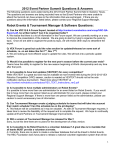
6. The VEX Cortex Software Inspection screen will open, and display information about your
VEX Cortex configuration.
The Cortex Master CPU Integrity section displays the Firmware Version of the Master CPU
Firmware, and whether it is up to date. If it is not up to date, you can download the Master
Firmware by going to Robot > Download Firmware > Master CPU Firmware > Standard File.
Note that if you download the Master CPU Firmware, you will have to re-sync the Cortex with
the VEXnet Joysticks.
The Cortex User CPU Integrity section displays the Firmware version of the ROBOTC User
Firmware, and whether it is up to date. If it is not up to date, you can download the ROBOTC
Firmware by going to Robot > Download Firmware > ROBOTC Firmware > Standard File.
Note that if you download the ROBOTC Firmware you will also have to redownload your
program to the robot.
Note: The VEX Cortex Software Inspection screen contains many other pieces of useful
information for making your robot competition-ready. Be sure to check the screen for any issues
before your competition!
© 2011 Carnegie Mellon Robotics Academy / For use with VEX Robotics Systems
Cortex Firmware Inspection - Using ROBOTC • 3
ROBOTC
VEX ROBOTICS COMPETITION
Cortex Firmware Inspection Using ROBOTC (cont.)
7. Unplug the Cortex. Plug one end of the USB A-to-A cable into the VEXnet Joysticks. Plug the other
end of the USB A-to-A cable into a USB port on the computer.
8. Select Software Inspection from the Robot menu in ROBOTC.
© 2011 Carnegie Mellon Robotics Academy / For use with VEX Robotics Systems
Cortex Firmware Inspection - Using ROBOTC • 4
ROBOTC
VEX ROBOTICS COMPETITION
Firmware Inspection Using ROBOTC (cont.)
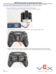
9. The VEX Cortex Software Inspection screen will open, and display information about your
VEXnet Joystick configuration.
The VEXnet Joystick Integrity section displays the Firmware Version of the VEXnet Joystick and
whether it is up to date. If it is not up to date, you can download the VEXnet Joystick Firmware
by going to Robot > Download Firmware > VEXnet Joystick Firmware > Standard File. Note
that if you download the VEXnet Joystick Firmware you will also have to re-sync the joysticks
with the Cortex and re-calibrate the joystick values.
Note: The VEX Cortex Software Inspection screen contains many other pieces of useful
information for making your robot competition-ready. Be sure to check the screen for any issues
before your competition!
© 2011 Carnegie Mellon Robotics Academy / For use with VEX Robotics Systems
Cortex Firmware Inspection - Using ROBOTC • 5
ROBOTC
VEX ROBOTICS COMPETITION
Testing VEX Cortex Robots using VEXnet
This document is an inspection guide for VEX Cortex based robots.
Use this document to test if a robot is competition ready.
Method I. Using the ROBOTC Competition Debug Window
You will need:
• A VEX Cortex and VEXnet Joysticks that have been paired/synced
• A computer with ROBOTC for Cortex and PIC 2.32 (or later) installed
• A VEX Programming Kit
• An object to prop the robot up, off of its wheels
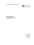
1. Connect the VEXnet Joysticks to the computer using the VEX Programming Kit.
1a. Connect to PC
Plug the USB connector on the
Programming Kit into the PC.
1b. Connect to VEXnet Joysticks
Plug the “phone cable” end of
the Programming Kit into the
PROGRAM port on the VEXnet
Joysticks.
2. Prop the robot up, so that its wheels are no longer touching a surface.
© 2011 Carnegie Mellon Robotics Academy / For use with VEX Robotics Systems
Testing VEX Cortex Robots using VEXnet • 1
ROBOTC
VEX ROBOTICS COMPETITION
Testing VEX Cortex Robots using VEXnet (cont.)
3. Turn on the VEX Cortex and VEXnet Joysticks and allow them to pair.
4. Open ROBOTC for Cortex and PIC
5. Verify that the Platform Type in ROBOTC is set to VEX 2.0 Cortex.
© 2011 Carnegie Mellon Robotics Academy / For use with VEX Robotics Systems
Testing VEX Cortex Robots using VEXnet • 2
ROBOTC
VEX ROBOTICS COMPETITION
Testing VEX Cortex Robots using VEXnet (cont.)
6. Establish a connection with the Cortex by going to the Robot menu and selecting Debugger.
7. After a connection has been established and the Program Debug window appears, go to Robot >
Debug Windows and select Competition Control.
8. The VEXnet Competition Control debug window will appear.
© 2011 Carnegie Mellon Robotics Academy / For use with VEX Robotics Systems
Testing VEX Cortex Robots using VEXnet • 3
ROBOTC
VEX ROBOTICS COMPETITION
Testing VEX Cortex Robots using VEXnet (cont.)
9. Press the Start button on the Program Debug window.
Note: After pressing the Start button, the robot will automatically go into User Control mode.
10. To test the robot’s autonomous mode, press the Autonomous button on the VEXnet
Competition Control window.
The code for autonomous mode will run once, until it is finished, or until you press
the Disabled button on the VEXnet Competition Control window. A stopwatch can be
used to time the duration of the autonomous mode, if desired. To run the code for the
autonomous period again, simply press the Autonomous button again.
11. To test the robot’s user control mode, press the User Control button on the VEXnet
Competition Control window.
The code for user control mode will run until you press the Disabled button on the VEXnet
Competition Control window. To restart the code for the user control period period, simply press
the User Control button again.
© 2011 Carnegie Mellon Robotics Academy / For use with VEX Robotics Systems
Testing VEX Cortex Robots using VEXnet • 4
ROBOTC
VEX ROBOTICS COMPETITION
Testing VEX Cortex Robots using VEXnet (cont.)
Method II. Using the VEXnet Competition Switch
You will need:
• A VEX robot and transmitter with paired VEXnet Upgrades
• A VEXnet Competition Switch
• An Ethernet Cable
• An object to prop the robot up, off of its wheels
1. Connect the VEXnet Joysticks to the VEXnet Competition Switch using an ethernet cable.
1a. Connect to the Joysticks
Plug one end of the ethernet
cable into the COMPETITION
port on the VEXnet Joysticks.
1b. Connect to Switch
Plug the the other end of
the ethernet cable into one
of the ports on the VEXnet
Competition Switch.
2. Set the ENABLE/DISABLE switch to DISABLE and the DRIVER/AUTONOMOUS switch to AUTONOMOUS.
© 2011 Carnegie Mellon Robotics Academy / For use with VEX Robotics Systems
Testing VEX Cortex Robots using VEXnet • 5
ROBOTC
VEX ROBOTICS COMPETITION
Testing VEX Cortex Robots using VEXnet (cont.)
3. Prop the robot up, so that its wheels are no longer touching a surface.
4. Turn on the VEX Cortex and VEXnet Joysticks and allow them to pair.
To test the robot’s autonomous mode, verify that the DRIVER/AUTONOMOUS switch is set to
AUTONOMOUS and change the ENABLE/DISABLE switch to ENABLE. The code for the autonomous
period will run once, until it is finished, or until it is disabled on the VEXnet Competition Switch. A
stopwatch can be used to time the duration of the autonomous mode, if desired. To run the code for
the autonomous period again, toggle the ENABLE/DISABLE switch to DISABLE and then to ENABLE.
To test the robot’s user control mode, first verify that the ENABLE/DISABLE switch is set to DISABLE.
Then, set the DRIVER/AUTONOMOUS switch to DRIVER and change the ENABLE/DISABLE switch to
ENABLE. The code for the user control period will run until it is disabled on the VEXnet Competition
Switch. To restart the code for the user control period again, toggle the ENABLE/DISABLE switch to
DISABLE and then to ENABLE.
© 2011 Carnegie Mellon Robotics Academy / For use with VEX Robotics Systems
Testing VEX Cortex Robots using VEXnet • 6
ROBOTC
VEX ROBOTICS COMPETITION
Testing VEX Cortex Robots using VEXnet (cont.)
Useful Information - The VEX Remote Screen
The ROBOTC Competition Templates are pre-programmed to display status information
to the VEX LCD Screen. Even if you don’t have the VEX LCD Screen attached to your
robot, you can use the ROBOTC VEX Remote Screen to view the information (along with
any other information you choose to display yourself).
To open the VEX Remote Screen, first open the ROBOTC Debugger. Then go to Robot >
Debug Windows, and select VEX Remote Screen.
Programming help for the VEX LCD Screen / VEX Remote Screen can be found in the
ROBOTC Help documentation under ROBOTC Functions > Display.
© 2011 Carnegie Mellon Robotics Academy / For use with VEX Robotics Systems
Testing VEX Cortex Robots using VEXnet • 7
ROBOTC
VEX ROBOTICS COMPETITION
VEX PIC Firmware Inspection Using ROBOTC
This document is part of a software inspection guide for VEX PIC based robots. Use this
document to determine what versions of the IFI Master firmware and ROBOTC user firmware are
loaded on a robot. For the most up-to-date firmware files download the latest version of
ROBOTC for Cortex and PIC at www.robotc.net.
You will need:
• Your VEX PIC Microcontroller with Battery
• A computer with ROBOTC for Cortex and PIC 2.32 or later installed (available at www.robotc.net)
• A VEX Programming Kit
1. Plug the USB connector end of the Programming cable into a USB port on your computer. Plug the other unconnected end of the cable into the SERIAL port of your VEX Microcontroller.
1a. Connect USB to PC
Plug the USB connector on the
Programming Kit into the PC.
1b. Connect to VEX
Plug the other end into the SERIAL
port on the VEX Microcontroller. If
your robot has the VEXnet Upgrade,
temporarily disconnect it.
2. Open ROBOTC for Cortex and PIC. ROBOTC will automatically recognize which USB port
your robot is connected to.
2. Open ROBOTC for Cortex and PIC
Open ROBOTC for Cortex and PIC
from your Desktop or Start Menu.
© 2011 Carnegie Mellon Robotics Academy / For use with VEX Robotics Systems
VEX PIC Firmware Inspection - Using ROBOTC • 1
ROBOTC
VEX ROBOTICS COMPETITION
VEX PIC Firmware Inspection Using ROBOTC (cont.)
3. Verify that the Platform Type in ROBOTC is set to VEX 0.5 Microchip.
4. If the VEX Microcontroller is not already turned on, turn it on now. 4. Turn the VEX Microcontroller on
Flip the small switch on your VEX Microcontroller to
turn your robot on, if it is not on already. Make sure
that a charged battery pack is connected.
5. Different features and options are available in ROBOTC depending on what mode is set.
Change to “Expert” mode by going to Window > Menu Level and selecting Expert.
© 2011 Carnegie Mellon Robotics Academy / For use with VEX Robotics Systems
VEX PIC Firmware Inspection - Using ROBOTC • 2
ROBOTC
VEX ROBOTICS COMPETITION
VEX PIC Firmware Inspection Using ROBOTC (cont.)
6. Establish a connection to the VEX Microcontroller by going to the Robot menu and selecting Debugger.
Note: The IFI Loader software and
other VEX programming solutions
also establish connections with the
VEX Microcontroller. If any of the
other software programs are open,
close them to ensure that ROBOTC
will be able to connect to the robot.
7. Once a connection is established, the Program Debug window will appear, along with any of the
other optional ROBOTC debug windows. Open the System Parameters debug window by going to
Robot > Debug Windows and selecting System Parameters.
8. The System Parameters debug window will appear as its own window, or docked as a tab within the
ROBOTC interface.
The firmwareVersion parameter refers to the ROBOTC user firmware and should be at least 7.31.
The nVEXMasterVersion parameter refers to the VEX master firmware and should be at least 10.
Note: If either firmware is out of date, they can
be downloaded using ROBOTC by going to the
Robot menu and selecting Download Firmware
for the ROBOTC firmware, or Download IFI
Master Firmware for the master firmware.
If you download the master firmware, you
must also download the ROBOTC firmware.
After downloading firmware, you must also redownload the user program to the VEX PIC.
© 2011 Carnegie Mellon Robotics Academy / For use with VEX Robotics Systems
VEX PIC Firmware Inspection - Using ROBOTC • 3
ROBOTC
VEX ROBOTICS COMPETITION
Firmware Inspection Using IFI Loader
This document is part of a software inspection guide for VEX v0.5 (75 MHz crystal) and VEX v1.5
(VEXnet Upgrade) microcontroller-based robots. Use this document to determine what versions of
the IFI Master firmware and ROBOTC user firmware are loaded on a robot.
You will need:
• Your VEX Microcontroller
• A computer with the IFI Loader software installed
(available at http://www.vexforum.com/wiki/index.php/Software_Downloads)
• A VEX Programming Kit
1. Plug the USB connector end of the Programming cable into a USB port on your computer.
Plug the other unconnected end of the cable into the SERIAL port of your VEX Microcontroller.
1a. Connect USB to PC
Plug the USB connector on the
Programming Kit into the PC.
1b. Connect to VEX
Plug the other end into the SERIAL
port on the VEX Microcontroller. If
your robot has the VEXnet Uprade,
temporarily disconnect it.
2. If the VEX was already connected to the computer with ROBOTC open, make sure that the Program
Debug window is closed to end the connection between ROBOTC and the robot.
2. Close the Debugger
If the Program Debug window is open,
close it to end the connection between
ROBOTC and the robot.
© 2010 Carnegie Mellon Robotics Academy / For use with VEX Robotics Systems
Firmware Inspection - Using IFI Loader • 1
ROBOTC
VEX ROBOTICS COMPETITION
Firmware Inspection Using IFI Loader (cont.)
2. Open the IFI Loader software from your Desktop or Start menu. The IFI Loader can be
downloaded from http://www.vexforum.com/wiki/index.php/Software_Downloads.
3. Once the IFI Loader software opens, select the port on your computer that the Programming Kit
is connected to by going to PortSettings and selecting the appropriate COM Port.
Note: The above graphic is only a sample, and may not reflect the port number that the Programming
Kit is connected to on your computer. You are able to view which port number your computer is using
using the Windows Device Manager (continue on for more details).
© 2010 Carnegie Mellon Robotics Academy / For use with VEX Robotics Systems
Firmware Inspection - Using IFI Loader • 2
ROBOTC
VEX ROBOTICS COMPETITION
Firmware Inspection Using IFI Loader (cont.)
Information - Windows Device Manager
To open the Windows Device Manager right-click on “My Computer” and select
“Properties”. Then select the “Hardware” tab and choose “Device Manager”.
Click on the “+” sign next to “Ports (COM & LPT)” to expand it. Look for the menu item
described as a USB-to-Serial Comm Port and make note of the COM number following it
in parenthesis. This is the port number you will use in the IFI Loader software.
4. After you select the appropriate COM port under PortSettings, go to the Options menu and
select Terminal Window.
© 2010 Carnegie Mellon Robotics Academy / For use with VEX Robotics Systems
Firmware Inspection - Using IFI Loader • 3
ROBOTC
VEX ROBOTICS COMPETITION
Firmware Inspection Using IFI Loader (cont.)
5. Once the Terminal Window is open, turn the VEX Microcontroller on. If it is already turned
on, turn it off, and then back on.
5. Power Cycle the VEX Microcontroller
Flip the small switch on your VEX Microcontroller
to turn your robot on. If it is already on, turn it off,
and then back on.
6. The Terminal Window will display both the master and ROBOTC user firmware.
The VEX Master firmware version should be at least 10.
The ROBOTC User firmware version should be at least 7.97.
Note: If either firmware is out of date, they can be downloaded using ROBOTC by going to the
Robot menu and selecting Download Firmare for the ROBOTC firmware, or Download IFI Master
Firmware for the master firmware.
If you download the master firmware, you must also download the ROBOTC firmware. After
downloading firmware, you must also re-download the user program to the VEX Microcontroller.
© 2010 Carnegie Mellon Robotics Academy / For use with VEX Robotics Systems
Firmware Inspection - Using IFI Loader • 4
ROBOTC
VEX ROBOTICS COMPETITION
Testing VEX PIC Robots with the 75 MHz Crystals
This document is an inspection guide for VEX v0.5 microcontroller-based robots.
Use this document to test if a robot using the 75 MHz crystals is competition ready.
You will need:
• A VEX robot and transmitter with matching 75 MHz crystals
• A stopwatch
• An object to prop the robot up, off of its wheels
1. Turn both the VEX Microcontroller and Radio Control Transmitter OFF.
2. Prop the robot up, so that its wheels are no longer touching a surface.
© 2010 Carnegie Mellon Robotics Academy / For use with VEX Robotics Systems
Testing VEX PIC Robots with the 75 MHz Crystals • 1
ROBOTC
VEX ROBOTICS COMPETITION
Testing VEX PIC Robots with the 75MHz Crystals (cont.)
3. Turn on the VEX Microcontroller.
4. Turn on the Radio Control Transmitter and observe the robot. You will need to use the transmitter
joysticks and buttons to test the user control period.
After turning on the transmitter, robots using the Competition Template will immediately run their
autonomous code for the amount of time specified within the template (20 seconds by default). During this time, moving the transmitter joysticks should have no effect on the behavior of the robot.
After the autonomous period has elapsed, the robot will automatically switch into user control mode and
enable radio control for the amount of time specified within the template (120 seconds by default). After the
user control period has ended, radio control will cease and the robot will stop. A stopwatch may be used to
confirm that the robot remains responsive to the transmitter controls for the desired amount of time.
Robots using the Driver Skills Template will immediately run their user control mode, enabling radio
control for the amount of time specified within the template (60 seconds by default). After the user control
period has ended, radio control will cease and the robot will stop.
Note: In either scenario, the Radio Control Transmitter must be on the entire time. For best results, fully
raise the antenna on the transmitter.
© 2010 Carnegie Mellon Robotics Academy / For use with VEX Robotics Systems
Testing VEX PIC Robots with the 75 MHz Crystals • 2
ROBOTC
VEX ROBOTICS COMPETITION
Testing VEX PIC Robots with the 75MHz Crystals (cont.)
Useful Information - The VEX Remote Screen
The ROBOTC Competition Templates are pre-programmed to display status information
to the VEX LCD Screen. Even if you don’t have the VEX LCD Screen attached to your
robot, you can use the ROBOTC VEX Remote Screen to view the information (along with
any other information you choose to display yourself).
To open the VEX Remote Screen, first open the ROBOTC Debugger. Then go to Robot >
Debug Windows, and select VEX Remote Screen.
Programming help for the VEX LCD Screen / VEX Remote Screen can be found in the
ROBOTC Help documentation under ROBOTC Functions > Display.
© 2010 Carnegie Mellon Robotics Academy / For use with VEX Robotics Systems
Testing VEX PIC Robots with the 75 MHz Crystals • 3
ROBOTC
VEX ROBOTICS COMPETITION
Testing VEX PIC ROBOTS with the VEXnet Upgrade
This document is an inspection guide for VEX v1.5 microcontroller-based robots.
Use this document to test if a robot using the VEXnet Upgrade is competition ready.
Method I. Using the ROBOTC Competition Debug Window
You will need:
• A VEX robot and transmitter with paired VEXnet Upgrades
• A computer with ROBOTC for Cortex and PIC 2.32 (or later) installed
• A VEX Programming Kit
• An object to prop the robot up, off of its wheels
1. Connect the VEXnet Upgrade on the Radio Control Transmitter to the computer using the VEX
Programming Kit.
1a. Connect to Transmitter
Plug the “phone cable” end
of the Programming Kit into
the SERIAL port of the VEXnet
Upgrade on the Transmitter.
1b. Connect to PC
Plug the USB connector on the
Programming Kit into the PC.
2. Prop the robot up, so that its wheels are no longer touching a surface.
© 2010 Carnegie Mellon Robotics Academy / For use with VEX Robotics Systems
Testing VEX PIC Robots with the VEXnet Upgrade • 1
ROBOTC
VEX ROBOTICS COMPETITION
Testing VEX PIC Robots with the VEXnet Upgrade (cont.)
3. Turn on the VEX robot and transmitter. Allow the VEXnet Upgrades to pair.
4. Open ROBOTC for Cortex and PIC
5. Verify that the Platform Type in ROBOTC is set to VEX 0.5 Microchip.
© 2010 Carnegie Mellon Robotics Academy / For use with VEX Robotics Systems
Testing VEX PIC Robots with the VEXnet Upgrade • 2
ROBOTC
VEX ROBOTICS COMPETITION
Testing VEX PIC Robots with the VEXnet Upgrade (cont.)
6. Establish a connection to the VEX Microcontroller by going to the Robot menu and selecting Debugger.
7. After a connection has been established and the Program Debug window appears, go to Robot >
Debug Windows and select Competition Control.
8. The VEXnet Competition Control debug window will appear.
© 2010 Carnegie Mellon Robotics Academy / For use with VEX Robotics Systems
Testing VEX PIC Robots with the VEXnet Upgrade • 3
ROBOTC
VEX ROBOTICS COMPETITION
Testing VEX PIC Robots with the VEXnet Upgrade (cont.)
9. Press the Start button on the Program Debug window.
Note: After pressing the Start button, the robot will automatically go into User Control mode.
10. To test the robot’s autonomous mode, press the Autonomous button on the VEXnet
Competition Control window.
The code for autonomous mode will run once, until it is finished, or until you press
the Disabled button on the VEXnet Competition Control window. A stopwatch can be
used to time the duration of the autonomous mode, if desired. To run the code for the
autonomous period again, simply press the Autonomous button again.
11. To test the robot’s user control mode, press the User Control button on the VEXnet
Competition Control window.
The code for user control mode will run until you press the Disabled button on the VEXnet
Competition Control window. To restart the code for the user control period period, simply press
the User Control button again.
© 2010 Carnegie Mellon Robotics Academy / For use with VEX Robotics Systems
Testing VEX PIC Robots with the VEXnet Upgrade • 4
ROBOTC
VEX ROBOTICS COMPETITION
Testing VEX PIC Robots with the VEXnet Upgrade (cont.)
Method II. Using the VEXnet Competition Switch
You will need:
• A VEX robot and transmitter with paired VEXnet Upgrades
• A VEXnet Competition Switch
• An Ethernet Cable
• An object to prop the robot up, off of its wheels
1. Connect the VEXnet Upgrade on the Radio Control Transmitter to the VEXnet Competition Switch
using the VEX ethernet cable.
1a. Connect to Transmitter
Plug one end of the ethernet
cable into the COMPETITION
port on the VEXnet Upgrade.
1b. Connect to Switch
Plug the the other end of
the ethernet cable into one
of the ports on the VEXnet
Competition Switch.
2. Set the ENABLE/DISABLE switch to DISABLE and the DRIVER/AUTONOMOUS switch to AUTONOMOUS.
© 2010 Carnegie Mellon Robotics Academy / For use with VEX Robotics Systems
Testing VEX PIC Robots with the VEXnet Upgrade • 5
ROBOTC
VEX ROBOTICS COMPETITION
Testing VEX PIC Robots with the VEXnet Upgrade (cont.)
3. Prop the robot up, so that its wheels are no longer touching a surface.
4. Turn on the VEX robot and transmitter. Allow the VEXnet Upgrades to pair.
To test the robot’s autonomous mode, verify that the DRIVER/AUTONOMOUS switch is set to
AUTONOMOUS and change the ENABLE/DISABLE switch to ENABLE. The code for the autonomous
period will run once, until it is finished, or until it is disabled on the VEXnet Competition Switch. A
stopwatch can be used to time the duration of the autonomous mode, if desired. To run the code for
the autonomous period again, toggle the ENABLE/DISABLE switch to DISABLE and then to ENABLE.
To test the robot’s user control mode, first verify that the ENABLE/DISABLE switch is set to DISABLE.
Then, set the DRIVER/AUTONOMOUS switch to DRIVER and change the ENABLE/DISABLE switch to
ENABLE. The code for the user control period will run until it is disabled on the VEXnet Competition
Switch. To restart the code for the user control period again, toggle the ENABLE/DISABLE switch to
DISABLE and then to ENABLE.
© 2010 Carnegie Mellon Robotics Academy / For use with VEX Robotics Systems
Testing VEX PIC Robots with the VEXnet Upgrade • 6
ROBOTC
VEX ROBOTICS COMPETITION
Testing VEX PIC Robots with the VEXnet Upgrade (cont.)
Useful Information - The VEX Remote Screen
The ROBOTC Competition Templates are pre-programmed to display status information
to the VEX LCD Screen. Even if you don’t have the VEX LCD Screen attached to your
robot, you can use the ROBOTC VEX Remote Screen to view the information (along with
any other information you choose to display yourself).
To open the VEX Remote Screen, first open the ROBOTC Debugger. Then go to Robot >
Debug Windows, and select VEX Remote Screen.
Programming help for the VEX LCD Screen / VEX Remote Screen can be found in the
ROBOTC Help documentation under ROBOTC Functions > Display.
© 2010 Carnegie Mellon Robotics Academy / For use with VEX Robotics Systems
Testing VEX PIC Robots with the VEXnet Upgrade • 7
ROBOTC
VEX ROBOTICS COMPETITION
ROBOTC Programming Competition Templates
This document is part of a software inspection guide for VEX based robots. Use this document to
learn how to use the “Competition Template” or “Driver Skills Template” included with ROBOTC.
For the most up-to-date versions of the templates (and ROBOTC) download the latest
version of ROBOTC for Cortex and PIC at www.robotc.net.
You will need:
• A computer with ROBOTC for Cortex and PIC 2.32 or later installed (available at www.robotc.net)
Normal Programming vs. Competition Programming
In ROBOTC, every program is usually based around task main(), as shown below:
task main()
{
//User code goes here
}
In a VEX competition, however, the robots need to communicate with the field control system, so
programming is a little different. To keep things simple, ROBOTC comes with built-in Competition
and Driver Skills templates. The templates contains three main sections, each mapped to specific
portions of the competition, where teams should place their code.
Part I. Using the ROBOTC Competition Template
1. Open ROBOTC for Cortex and PIC.
1. Open ROBOTC for Cortex and PIC
Open ROBOTC for Cortex and PIC
from your Desktop or Start Menu.
2. To begin programming in a Competition Template, go to File > New... and select Competition Template.
© 2011 Carnegie Mellon Robotics Academy / For use with VEX Robotics Systems
ROBOTC Programming - Competition Templates • 1
ROBOTC
VEX ROBOTICS COMPETITION
ROBOTC Programming Competition Templates (cont.)
3. A new file named Competition.c will appear. Before making any changes to the template, go to File,
select Save As... and save this program in a location and under a name you will remember.
Shown below are the contents of the Competition.c file with brief descriptions, but with the comments
removed. Additional details are available throughout the document.
#pragma platform(VEX)
This pragma statement specifies
the VEX as the platform type.
#pragma competitionControl(Competition)
This pragma statement enables
competition control.
#pragma autonomousDuration(20)
#pragma userControlDuration(120)
These pragma statements specify the
duration (20 and 120 second defaults) of the
autonomous and user control modes for VEX
PIC based robots using the 75 MHz Crystals.
VEX Cortex and VEX 1.5 (VEXnet Upgraded
PIC) based robots will ignore these lines;
which mode they are in and the duration are
controlled using the field control system.
#include “Vex_Competition_Includes.c”
This include file contains the functionality
necessary for the robot to operate with the
VEX field control. Do NOT modify the include
file or remove this line of code.
void pre_autonomous()
{
//Place pre-autonomous code here
}
task autonomous()
{
//Place autonomous code here
AutonomousCodePlaceholderForTesting();
}
task usercontrol()
{
while(true)
{
//Place user control code here
UserControlCodePlaceholderForTesting();
}
}
© 2011 Carnegie Mellon Robotics Academy / For use with VEX Robotics Systems
Any initialization code, such as setting
servo positions or clearing encoder
values can be placed within the
pre_autonomous() function.
All code for the autonomous portion
of the competition should be placed
within the autonomous task. The
AutonomousCodePlaceholderForTesting
function can be removed once you place your
own code within the task.
All code for the user control portion of the
competition should be placed within the while()
loop of the usercontrol task. The while() loop
repeats all commands within its curly brackets
for the duration of the user control portion of
the competition, ensuring that the transmitter
data and any other values are up-to-date. The
UserControlCodePlaceholderForTesting
function can be removed once you place your
own code within the task.
ROBOTC Programming - Competition Templates • 2
ROBOTC
VEX ROBOTICS COMPETITION
ROBOTC Programming Competition Templates (cont.)
Setting up Competition Control and Timing
In ROBOTC, competition programming is completely user customizable, so no jumpers are
required for testing. By adjusting the following commands, the templates can be adapted to
work in any VEX supported competition.
#pragma competitionControl(Competition)
#pragma autonomousDuration(20)
#pragma userControlDuration(120)
#pragma competitionControl(competition_mode) - Controls the competition mode that
the VEX is in. There are two different competition modes that you can pass:
OFF - No competition control.
Competition - The VEX will respond to field control commands and switch between
Autonomous and User Control modes at the competition-specified times. Use this mode for
competitions.
#pragma autonomousDuration(time_in_seconds) Defines the duration of the autonomous phase of a VEX competition for VEX PIC robots using the 75
MHz crystals. To use the competition template in a User Control-only competition, you can set the
duration to zero. This line can be deleted or commented-out if you are using the VEX Cortex or a VEX 1.5
(VEXnet Upgraded PIC) based robot. #pragma userControlDuration(time_in_seconds) - Defines the duration of the user control phase of a VEX competition for robots using the 75 MHz crystals.
To use the competition template in an Autonomous-only competition, you can set the duration to
zero. This line can be deleted or commented-out if you are using the VEX Cortex or a VEX 1.5 (VEXnet
Upgraded PIC) based robot.
Important Information - Timing Tips
For robots using the 75MHz crystals, the user control duration can be increased beyond the actual
length of the round to compensate for any possible delays in the system. For example, changing
userControlDuration(120) to userControlDuration(180) would ensure that the robot
remains active until the Field Control system ends the user control period.
The durations of VEX Cortex and VEX 1.5 based robots are determined solely by the Field Control
system. When programming VEX Cortex or VEX 1.5 based robots, so you can comment-out or
delete the autonomousDuration() and userControlDuration() pragma statements.
© 2011 Carnegie Mellon Robotics Academy / For use with VEX Robotics Systems
ROBOTC Programming - Competition Templates • 3
ROBOTC
VEX ROBOTICS COMPETITION
ROBOTC Programming Competition Templates (cont.)
Pre-Autonomous Period
Place your initialization code inside this function. During the pre-autonomous period, code can be
executed to configure your robot before the actual competition begins. Valid code for this section
includes tasks such as clearing encoders, reflecting motors, and setting initial servo positions. void pre_autonomous()
{
//Place pre-autonomous code here
}
Note: This code executes only once and runs before the competition begins.
Autonomous Period
Place your autonomous code inside this task. During the autonomous period, the robot performs the
pre-programmed actions once, or until it is disabled by the field control system (or for the length of
time specified in the autonomousDuration(time) pragma statement, for VEX PIC based robots
using the 75 MHz Cystals). The AutonomousCodePlaceholderForTesting(); function is only a
placeholder and should be replaced with your own code.
task autonomous()
{
//Place autonomous code here
AutonomousCodePlaceholderForTesting();
}
Important Information - Transmitter Signal
VEX PIC based robots using the 75 MHz Crystals cannot accept commands from the Radio Control
Transmitter during the autonomous period, but they require that the signal be present as a safety
precaution. The autonomous period during a competition cannot be skipped by shutting the transmitter off;
doing so with a robot using the 75 MHz crystals will pause the VEX’s internal timers, potentially causing the
robot to enter the User Control period later than it should.
Also note that the AutonomousCodePlaceholderForTesting(); function contains a while(true)
loop that can prevent user-written autonomous code from executing. Remove this function to avoid any
unexpected behavior during the autonomous period.
© 2011 Carnegie Mellon Robotics Academy / For use with VEX Robotics Systems
ROBOTC Programming - Competition Templates • 4
ROBOTC
VEX ROBOTICS COMPETITION
ROBOTC Programming Competition Templates (cont.)
User Control Period
Place your user control code inside this task. During the user controlled period, the robot accepts
commands from the VEXnet Joysticks (VEX Cortex based robots) or the Radio Control Transmitter (VEX PIC
based robots). This segment of code typically executes immediately after the autonomous period ends.
The UserControlCodePlaceholderForTesting(); function is only a placeholder and should be
removed once you place your own code inside of the while(true) loop.
task usercontrol()
{
while(true)
{
//Place user control code here
UserControlCodePlaceholderForTesting();
}
}
Important Information - while(true) loop
When programming for the user control period, place all commands inside of the while(true) loop. Failing
to do so will result in the commands only running once, preventing you from remotely controlling your robot.
The field control system determines and controls the maximum length of the user control period.
© 2011 Carnegie Mellon Robotics Academy / For use with VEX Robotics Systems
ROBOTC Programming - Competition Templates • 5
ROBOTC
VEX ROBOTICS COMPETITION
ROBOTC Programming Competition Templates (cont.)
Sample Competition Template with User Code
#pragma config(Sensor, in1, bumper, sensorTouch)
//*!!Code automatically generated
#pragma platform(VEX)
Motors and Sensors configured using
the ROBOTC Motors and Sensors
setup window will automatically be
added as pragma statements at the
top of the program.
#pragma competitionControl(Competition)
#pragma autonomousDuration(20)
#pragma userControlDuration(120)
#include “Vex_Competition_Includes.c”
void forwardUntilTouch()
{
while(SensorValue[bumper] == 0)
{
motor[port2] = 63;
motor[port3] = 63;
}
motor[port2] = 0;
motor[port3] = 0;
}
void pre_autonomous()
{
bMotorReflected[port2] = true;
}
task autonomous()
{
forwardUntilTouch();
motor[port6] = 31;
wait1Msec(250);
motor[port6] = 0;
}
task usercontrol()
{
while(true)
{
motor[port2] = vexRT[Ch2];
motor[port3] = vexRT[Ch3];
motor[port6] = vexRT[Ch6]/4;
}
}
© 2011 Carnegie Mellon Robotics Academy / For use with VEX Robotics Systems
While it’s not technically required,
it’s good programming practice to
place user-defined functions and/or
global variables below the pragma
and include statements, and above the
template-included functions and tasks.
This sets the motor connected to VEX
Port 2 to spin in reverse.
Commands in the autonomous period
are executed once (assuming there are no
loops in the code). Also, notice that the AutonomousCodePlaceholderForTesting function has been removed.
Commands in the while(true)
loop of the user control period
are executed until the end of
the match. Also, notice that the
UserControlCodePlaceholderForTesting function has been
removed from the loop.
ROBOTC Programming - Competition Templates • 6
ROBOTC
VEX ROBOTICS COMPETITION
ROBOTC Programming Competition Templates (cont.)
Part II. Using the ROBOTC Driver Skills Template
Using the ROBOTC Driver Skills Template is very similar to using the ROBOTC Competition Template.
The two templates are nearly identical; the only difference between the two are comments in the code,
the autonomous duration is set to zero seconds by default, the user control duration is set to sixty
seconds by default, and basic remote control commands are already placed within the while(true) loop
of the user control section of the program.
1. Open ROBOTC for Cortex and PIC.
1. Open ROBOTC for Cortex and PIC
Open ROBOTC for Cortex and PIC
from your Desktop or Start Menu.
2. To begin programming in a Driver Skills Template, go to File > New... and select Driver Skills Template.
3. A new file named DriverSkills.c will appear. Before making any changes to the template, go to File,
select Save As... and save this program in a location and under a name you will remember.
© 2011 Carnegie Mellon Robotics Academy / For use with VEX Robotics Systems
ROBOTC Programming - Competition Templates • 7
ROBOTC
VEX ROBOTICS COMPETITION
ROBOTC Programming Competition Templates (cont.)
Shown below are the contents of the DriverSkills.c file with brief descriptions, but with the comments
removed and additional spacing added. Additional details can be found in Part I of this document.
#pragma platform(VEX)
#pragma competitionControl(Competition)
These pragma statements specify the
duration of the autonomous and user control
portions of the competition (0 and 60 second
defaults)for VEX PIC based robots using the
75 MHz Crystals.
#pragma autonomousDuration(0)
#pragma userControlDuration(60)
If your robot is using the 75 MHz crystals,
do NOT remove these lines of code. If you
are using a VEX Cortex or VEX 1.5 (VEXnet
Upgraded PIC) based robot, you can
comment these lines out or delete them.
#include “Vex_Competition_Includes.c”
void pre_autonomous()
{
//Place pre-autonomous code here
}
Any initialization code, such as setting
servo positions or clearing encoder
values can be placed within the
pre_autonomous() function.
task autonomous()
{
//Leave this section alone
AutonomousCodePlaceholderForTesting();
}
task usercontrol()
{
while(true)
{
//Place user control code here
UserControlCodePlaceholderForTesting();
motor[port2] = vexRT[Ch1];
motor[port3] = vexRT[Ch4];
}
}
© 2011 Carnegie Mellon Robotics Academy / For use with VEX Robotics Systems
The autonomous task can be ignored when
programming for a Driver Skills competition,
but do NOT delete it.
All code for the user control portion of the
competition should be placed within the while()
loop of the usercontrol task. The while() loop
repeats all commands within its curly brackets
for the duration of the user control portion of the
competition, ensuring that the remote control
values sent to the robot are continually updated.
The pre-existing code within the loop can
be replaced with your own code. The
UserControlCodePlaceholderForTesting
function should also be removed.
ROBOTC Programming - Competition Templates • 8
ROBOTC
Setup
Driver Installation
In this lesson, you will learn how to install the USB-to-Serial Cable driver. Make
sure you have sufficient security privileges to install drivers on the computer
before you begin.
You will need:
1. A ROBOTC for IFI Installation CD or an Internet connection
2. A VEX USB-to-Serial cable
1. Plug the USB connector end into your computer.
1. Connect the cable
Plug the USB end of the
cable into the computer.
© 2007 Carnegie Mellon Robotics Academy / For use with VEX Robotics Systems
Driver Installation • 1
ROBOTC
Setup
Driver Installation
2. Cancel any automatic installation prompts that may appear, such as the “Found New
Hardware Wizard” Window. Instead, run the driver installation program manually from the
ROBOTC for IFI CD-ROM or download and run the driver from the ROBOTC.net website.
For downloading instructions, see step 3.
2a. Cancel any installation wizard
The driver installation does not
require the use of the “Found New
Hardware Wizard”.
2b. Run the Driver
The USB-to-Serial driver installation
can be run from the ROBOTC for IFI
installation CD.
© 2007 Carnegie Mellon Robotics Academy / For use with VEX Robotics Systems
Driver Installation • 2
ROBOTC
Setup
Driver Installation
3. If you download the driver from ROBOTC.net, the installation file will need to be extracted before you
can start the installation process. Extract the “prolific_usb_driver” file by right-clicking its icon, selecting
“Extract All...”, and proceeding through the following steps. Once complete, run the “SETUP” file and
follow the its instructions to finish installing the USB-to-Serial driver.
3a. Download driver
If you do not have
the CD, you can
download the
driver from the VEX
“Download” page of
ROBOTC.net.
3b. Extract the driver
Right click and extract the
“SETUP” file.
3c. Install the driver
Double click the
“SETUP” file to begin
the installation.
© 2007 Carnegie Mellon Robotics Academy / For use with VEX Robotics Systems
Driver Installation • 3
ROBOTC
Setup
Driver Installation
4. Follow the installation prompts to complete the installation.
4a. Follow prompts
Complete the installation according
to the onscreen instructions.
4b. Finish the installation
Unplug the USB-to-Serial
cable and plug it back in to
complete the installaton.
© 2007 Carnegie Mellon Robotics Academy / For use with VEX Robotics Systems
Driver Installation • 4
ROBOTC
Setup
VEX Cortex Configuration over USB
The VEX Cortex is a fully programmable device, and is what enables you to incorporate motors,
sensors, an LCD screen, and remote control signals all in one robot. Inside of the Cortex,
there are two separate processors; a user processor handles all of the ROBOTC programming
instructions, and a master processor controls lower-level operations, like motor control and
VEXnet communication. This document is a guide for downloading the Master CPU firmware and
ROBOTC firmware to the VEX Cortex using the USB A-to-A cable.
You will need:
• 1 VEX Cortex Microcontroller with one 7.2V Robot Battery
• A computer with ROBOTC for Cortex and PIC installed
• 1 USB A-to-A Cable
1. Leaving the POWER switch in the OFF position, connect your Cortex to the computer using the USB
A-to-A cable. Once the cable is attached, move the POWER switch to the ON position.
1a. Connect the Cortex to your PC
Use the USB A-to-A cable to connect your Cortex
to your PC.
Note: The order detailed in this step is crucial.
When the Cortex is powered on, it immediately
tries to determine how it is connected (over VEXnet,
USB, or no connection). Some power is provided
to the Cortex over USB, which will allow it to
determine that it is connected to your computer.
1b. Turn the Cortex ON
Make sure a 7.2V Robot battery is connected
and move the POWER switch on the Cortex to
the ON position.
Note: If your Cortex is connected to a mobile
robot, it’s recommended that you prop the
robot up to prevent its wheels from making
contact with a surface. The motors may turn on
and off during the firmware download process.
© 2011 Carnegie Mellon Robotics Academy / For use with VEX Robotics Systems
VEX Cortex Configuration over USB • 1
ROBOTC
Setup
VEX Cortex Configuration over USB (cont.)
2. Specify that you are using the Cortex and how it is connected to your computer in ROBOTC.
2a. Detailed Preferences...
Go to View > Preferences
and select Detailed
Preferences...
2b. Platform Settings
Make sure that the
Platform tab is selected
on the ROBOTC
Preferences window.
Next, specify the
Natural Language
(VEX Cortex) as your
Platform Type.
Finally, to program
directly over the USB
A-to-A cable, select the
option that specifys the
USB Wired Cable.
Press OK to finalize
your settings.
Note: The Platform Type can also be modified by going to the Robot menu in ROBOTC, selecting Platform
Type, and choosing one of the available options. Also, the Automatic Selection option should be used if you
will be switching between VEXnet using the USB-to-Serial Programming Cable, and the USB A-to-A Cable.
© 2011 Carnegie Mellon Robotics Academy / For use with VEX Robotics Systems
VEX Cortex Configuration over USB • 2
ROBOTC
Setup
VEX Cortex Configuration over USB (cont.)
3. The VEX Cortex Download Method controls how ROBOTC downloads firmware and programs
to your Cortex, as well as what types of connections your Cortex checks for when it is powered
on. Confirm that your VEX Cortex Download Method is set to Download Using VEXnet or USB
or Download Using USB Only.
Option 1: Download Using VEXnet or USB
With this option selected, ROBOTC will download ROBOTC firmware and programs to your
Cortex using a VEXnet or USB connection. In this mode, when the Cortex is powered ON it
will look for a VEXnet or USB connection for up to 10 seconds before running your program.
(The Automatic Selection option in the ROBOTC Preferences should be selected if you plan on
switching between VEXnet and USB as your download method.)
Option 2: Download Using USB Only
With this option selected, ROBOTC will download firmware and programs to your Cortex
using only the USB connection. In this mode, when the Cortex is powered ON it will
immediately run your program. This option is NOT recommended if you are using the VEXnet
Joysticks to download to the Cortex, or remotely control it.
Option 1: Download for Competition (VEXnet)
This option disables the ROBOTC debugger, and is not recommended for classroom use.
Important Note: Restarting the Cortex
The VEX Cortex Download Method setting is stored in ROBOTC and on the Cortex. If you
change the setting, the Cortex must be power cycled (turned fully off, and then back on)
before the change will take effect.
© 2011 Carnegie Mellon Robotics Academy / For use with VEX Robotics Systems
VEX Cortex Configuration over USB • 3
ROBOTC
Setup
VEX Cortex Configuration over USB (cont.)
4. Go to Robot > Download Firmware > Master CPU Firmware and select Standard File to
download the latest Master CPU Firmware to your robot.
4. Download Progress
A Download Progress window will appear and begin the download process. When the window
closes, the firmware download is complete. A ROBOTC Message will appear, and remind you to
also download the ROBOTC Firmware.
Note: You only need to download the Master CPU Firmware once,
when you first start using a VEX Cortex with ROBOTC, or when you
upgrade to a newer version of ROBOTC. Switching programs or
download methods does not require a re-download.
© 2011 Carnegie Mellon Robotics Academy / For use with VEX Robotics Systems
VEX Cortex Configuration over USB • 4
ROBOTC
Setup
VEX Cortex Configuration over USB (cont.)
5. The ROBOTC Firmware enables you to download ROBOTC programs to your robot and utilize the
various debug windows. Go to Robot > Download Firmware > ROBOTC Firmware and select
Standard File to download the ROBOTC Firmware to your robot.
5. Download Progress
A Download Progress window will appear and begin the download process. When the window closes,
the firmware download is complete.
Note: You only need to download the ROBOTC Firmware once, when you first start using a VEX Cortex
with ROBOTC, or when you upgrade to a newer version of ROBOTC.
End of Lesson
Once the Download Progress window closes, the ROBOTC Firmware download is complete.
Your VEX Cortex is now ready to be programmed in ROBOTC.
If you are also using the VEXnet Joysticks, you can follow the provided instructions in the VEXnet
Joysticks Setup document. Otherwise, move on to the Downloading Sample Programs over USB
guide to learn how to download sample code, and verify that your setup is fully functional.
© 2011 Carnegie Mellon Robotics Academy / For use with VEX Robotics Systems
VEX Cortex Configuration over USB • 5
ROBOTC
Setup
VEXnet Joystick Configuration in ROBOTC
The VEXnet Joystick enables more than just the remote control of your robot. It also provides
the wireless communication link between your computer and the VEX Cortex, enabling you to
wirelessly download firmware, programs and run the ROBOTC debugger. In this document,
you will learn how to configure VEXnet Joystick using ROBOTC.
This document is broken into 3 sections:
1. Downloading Firmware to the VEXnet Joystick
2. Creating a Wireless Link Between the VEXnet Joystick and VEX Cortex
3. Calibrating the VEXnet Joystick Values
You will need:
• 1 VEXnet Joystick with 6 AAA Batteries
• 1 Small Phillips Screwdriver
• A computer with ROBOTC for Cortex and PIC installed
• 1 USB A-to-A Cable
• 1 USB-to-Serial Programming Cable
Section 1: Downloading Firmware to the VEXnet Joystick
1. Begin by installing 6 AAA batteries in the VEXnet Joystick. You will need a small Phillips screwdriver to
remove the battery cover.
1a. Install 6 AAA Batteries
Remove the battery cover using a small Phillips
screwdriver and install 6 AAA batteries, being
careful to align them as indicated.
1b. Verify Correct Installation
Turn the VEXnet Joystick ON to verify that you
correctly installed the batteries. If any of the LED’s
on the front turn on, you installed the batteries
correctly. Turn the controller OFF and secure the
battery cover using the Philips screwdriver.
© 2011 Carnegie Mellon Robotics Academy / For use with VEX Robotics Systems
VEX Cortex Configuration over USB • 1
ROBOTC
Setup
VEXnet Joystick Configuration in ROBOTC (cont.)
2. Connect the VEXnet Joystick to your computer using the USB A-to-A cable and turn it ON.
2a. Connect the VEXnet Joystick
Use the USB A-to-A cable to connect your
VEXnet Joystick to your computer.
Note: The VEXnet light should turn green.
2b. Turn the VEXnet Joystick ON
Switch the VEXnet Joystick to the ON postion.
Note: The Joystick light should turn green.
© 2011 Carnegie Mellon Robotics Academy / For use with VEX Robotics Systems
VEX Cortex Configuration over USB • 2
ROBOTC
Setup
VEXnet Joystick Configuration in ROBOTC (cont.)
3. Go to Robot > Download Firmware > VEXnet Joystick Firmware and select Standard File to
download the latest VEXnet Joystick Firmware to the controller.
3. Download Progress
A Download Progress window will appear and begin the download process. When the window
closes, the firmware download is complete.
Note: You only need to download the VEXnet Joystick Firmware once, when you first start using a
VEX Cortex with ROBOTC, or when you upgrade to a newer version of ROBOTC.
End of Section: Downloading Firmware to the VEXnet Joystick
Once the Download Progress window closes, the VEXnet Joystick Firmware download is complete.
Move on to the next section to learn how to create a wireless link between the VEXnet Joystick and
VEX Cortex.
© 2011 Carnegie Mellon Robotics Academy / For use with VEX Robotics Systems
VEX Cortex Configuration over USB • 3
ROBOTC
Setup
VEXnet Joystick Configuration in ROBOTC (cont.)
Section 2: Creating a wireless link betwen the VEXnet Joystick and VEX Cortex
In this section, you will learn how to pair a VEX Cortex Microcontroller to a VEXnet Joystick,
allowing them to communicate over VEXnet. This section assumes that you have already updated
the master firmware on the VEX Cortex and VEXnet Remote Control.
VEXnet is an 802.11 WiFi communication system between the VEX Cortex and VEXnet Remote Control.
VEXnet features include:
• Easy to connect (No IP addresses, MAC addresses, passwords, or special security modes)
• Multiple layers of security built-in and always on
• No wireless access point needed; each VEXnet pair makes its own private network
• Hundreds of robots can operate at once; every VEXnet robot has a hidden unique ID
• Optional tether for wired communication
• Optional 9V battery backup to maintain wireless link during a main 7.2V power loss
• LED scheme displays the status of the Robot, VEXnet link, and Game (Competition Mode)
1. Begin by verifying that both the Cortex and VEXnet Joystick are connected to charged batteries.
1a. Connect a Battery to the Cortex
Connect a 7.2V robot battery to the Cortex,
but do not power it ON.
1b. Install Batteries in the VEXnet Remote Control
Remove the battery cover plate on the remote
control. Install 6 AAA batteries, and replace the
battery cover plate. Do not power the remote
control ON.
© 2011 Carnegie Mellon Robotics Academy / For use with VEX Robotics Systems
VEX Cortex Configuration over USB • 4
ROBOTC
Setup
VEXnet Joystick Configuration in ROBOTC (cont.)
2. Tether the USB port on the VEXnet Joystick to the USB port on the Cortex using a USB
A-to-A cable.
2a. VEXnet Joystick USB Port
Plug one end of the USB A-to-A cable into
the USB port on the VEXnet Joystick.
2b. VEX Cortex USB Port
Plug the other end of the USB A-to-A cable
into the USB port on the VEX Cortex.
3. Power the Cortex ON. After a few seconds, ROBOT and VEXnet LEDs will blink green,
indicating that the Cortex and VEXnet Joystick have successfully paired.
3a. Turn the Cortex ON
3b. Status LEDs
The ROBOT and VEXnet LEDs will blink
green once the Cortex and VEXnet
Joystick have successfully paired. The
GAME LED will also blink green if a
program is stored on your Cortex.
© 2011 Carnegie Mellon Robotics Academy / For use with VEX Robotics Systems
VEX Cortex Configuration over USB • 5
ROBOTC
Setup
VEXnet Joystick Configuration in ROBOTC (cont.)
4. Turn the Cortex OFF.
5. Remove the USB A-to-A cable from the VEXnet Joystick and Cortex.
6. Insert VEXnet USB Keys into both the VEXnet Joystick and Cortex.
6. VEXnet USB Keys
Insert VEXnet USB Keys into the
VEXnet Joystick and Cortex.
Note:
It does not matter which VEXnet USB
Key you insert into the Cortex versus
the VEXnet Joystick. Pairing the Cortex
and VEXnet Joystick establishes the
link; the VEXnet USB Keys simply act as
antennas for the link.
© 2011 Carnegie Mellon Robotics Academy / For use with VEX Robotics Systems
VEX Cortex Configuration over USB • 6
ROBOTC
Setup
VEXnet Joystick Configuration in ROBOTC (cont.)
7. Power the Cortex and Joystick ON. After roughly 15 seconds, the ROBOT and VEXnet LED’s
will blink green, indicating that the VEXnet communication link has been established.
7a. Turn the Cortex ON
7b. Turn the VEXnet Joystick ON
7c. Status LEDs
After roughly 15 seconds, the ROBOT and
VEXnet status LEDs will start quickly blinking
green. With the VEXnet link established, you
should power OFF your Cortex and VEXnet
Joystick to preserve battery.
End of Section: Creating a Wireless Link between the VEXnet Joystick and VEX Cortex
Your VEXnet Joystick and VEX Cortex can now communicate over the VEXnet USB Keys. Move on to
the next section to calibrate the values your VEXnet Joystick sends out.
© 2011 Carnegie Mellon Robotics Academy / For use with VEX Robotics Systems
VEX Cortex Configuration over USB • 7
ROBOTC
Setup
VEXnet Joystick Configuration in ROBOTC (cont.)
Section 3: Calibrating the VEXnet Joystick Values
This section contains the procedure for calibrating the VEXnet Remote Control joysticks.
Some steps are time-sensitive, so it’s recommended that you read through the instructions once
before following along.
The VEXnet Remote Control includes two joysticks (each having an X and Y-axis), 8 buttons on
the front, and 4 additional trigger buttons on the top. Inside, there is also 3-Axis accelerometer,
capable of providing X-Y-Z acceleration values. Values from the joysticks, buttons, and
accelerometer are sent as a constant stream of information over VEXnet to the robot, enabling a
user to control the robot in real-time.
To ensure that the VEXnet Joystick sends out accurate joystick values, the joysticks must be
calibrated before their first use, and after any firmware updates are applied.
You will need:
• A VEXnet Joystick with batteries
• A VEX Cortex with robot battery
• A small Allen wrench (1/16” or smaller) or paper clip
1. Power on the VEXnet Joystick and VEX Cortex. Allow them to sync over VEXnet.
© 2011 Carnegie Mellon Robotics Academy / For use with VEX Robotics Systems
VEX Cortex Configuration over USB • 8
ROBOTC
Setup
VEXnet Joystick Configuration in ROBOTC (cont.)
2. Press and hold the 6U trigger button.
2. Press and hold the 6U trigger button
3. While keeping the 6U trigger button pressed in, use your Allen wrench or paper clip to press in the
internal CONFIG button until the JOYSTICK LED blinks red and green.
3a. Press and the CONFIG button
While still pressing in the 6U trigger button,
use an Allen wrench or paper clip to press in
the CONFIG button.
3b. JOYSTICK LED
Once the JOYSTICK LED begins to blink
red and green, release both the 6U and
CONFIG buttons.
© 2011 Carnegie Mellon Robotics Academy / For use with VEX Robotics Systems
VEX Cortex Configuration over USB • 9
ROBOTC
Setup
VEXnet Joystick Configuration in ROBOTC (cont.)
Important - Time Sensitive Instructions
There is a 10 second time limit to complete steps 4 and 5. If they are not completed in
time, the calibration process will timeout and the VEXnet LED will blink red briefly.
4. Move both joysticks through their full ranges of motion. When the remote control detects
that the joysticks have been fully rotated, the JOYSTICK LED stops blinking red and green,
and switches to a solid green.
4a. Move the Joysticks
Move the joysticks through their full ranges of
motion - Up, Down, Left, Right, and in a circle.
4b. JOYSTICK LED
Once the remote control detects that the joysticks
have been fully rotated, the JOYSTICK LED switches
to solid green, indicating that you can stop moving
the joysticks.
© 2011 Carnegie Mellon Robotics Academy / For use with VEX Robotics Systems
VEX Cortex Configuration over USB • 10
ROBOTC
Setup
VEXnet Joystick Configuration in ROBOTC (cont.)
5. Press the 8U button to save the new calibration.
5. Save
Press the 8U button to save the joystick calibration
on your remote control. The JOYSTICK LED will
blink green for a few seconds.
Additional Information
• If the calibration is not saved, the process will timeout after 10 seconds and
the VEXnet LED will blink red.
• To cancel a calibration, press the 7U button. The calibration process will be
discontinued and the VEXnet LED will blink red.
• Once the calibration is discontinued or saved, all of the remote control LEDs
will resume their normal function.
• The joysticks must be calibrated any time the firmware on the remote control
is downloaded.
End of Section: Calibrating the VEXnet Joystick Values
The joysticks on your VEXnet Joystick are now properly calibrated and ready to be used to remote
control your robot. If you had any issues during the process, troubleshooting tips can be found on
the following page.
© 2011 Carnegie Mellon Robotics Academy / For use with VEX Robotics Systems
VEX Cortex Configuration over USB • 11
ROBOTC
Setup
VEXnet Joystick Configuration in ROBOTC (cont.)
Troubleshooting
Issue: Slow blinking green ROBOT light on the Cortex
Solution: Download the Cortex Master Firmware using ROBOTC.
Issue: Slow blinking ROBOT green light on the VEXnet Joystick
Solution: Push and hold CONFIG button for about 5 seconds, until the status
LEDs starts blinking green. Release it, wait for another 5 seconds, and then turn
the VEXnet Joystick OFF and then back ON. If that fails, download the VEXnet
Joystick Firmware using ROBOTC.
Issue: Yellow or red ROBOT light on the Cortex
Solution: Make sure you are using fully charged Robot battery.
Issue: Yellow or red ROBOT light on the VEXnet Joystick, even though they are
both green on the Cortex.
Solution: Power cycle both the VEXnet Joystick and CORTEX.
© 2011 Carnegie Mellon Robotics Academy / For use with VEX Robotics Systems
VEX Cortex Configuration over USB • 12
ROBOTC
Setup
Master Firmware
Download Instructions
In this document, you will learn how to download the IFI Master CPU Firmware to the
VEX Microcontroller.
What is the Master Firmware?
The VEX Microcontroller contains two processors: a user processor that handles all of the ROBOTC
instructions, and a master processor that handles lower-level operations like motor control and
radio communication. The IFI Master CPU Firmare, or master firmware, is a program that allows
the master processor to complete the lower-level operations. Every VEX Microcontroller is preloaded
with a version of the master firmware, but downloading the latest version will ensure that your robot
is compatible with the latest hardware available.
Before you begin, make sure:
• Your VEX is connected to a charged battery
• You have an orange USB-to-Serial programming cable
• ROBOTC 2.0 or later is installed on your computer
1. Plug the Robot Interface (“telephone”) Cable and the USB-to-Serial cable into the
Programming Module.
1a. Connect USB-to-Serial Cable
to Programming Module
Plug the 9-pin Serial end of
the USB-to-Serial Cable into
the matching port on the
Programming Module.
1b. Connect Robot Interface Cable to Programming Module
Plug the end of the RJ25 “telephone”
cable into the matching port on the
Programming Module.
© Carnegie Mellon Robotics Academy / For use with VEX® Robotics Systems
Master Firmware Download • 1
ROBOTC
Setup
Master Firmware Download Instructions
(cont.)
2. Power the VEX Microcontroller and connect it to your computer using the orange
USB-to-Serial programming cable.
2a. Power the VEX Microcontroller
Connect the VEX Microcontroller to a
charged 7.2V battery and turn it ON.
2b. Connect the VEX to the Computer
Use the orange USB-to-Serial programming cable to
connect the VEX to your computer. If you are using the
VEXnet Microcontroller Upgrade, temporarily unplug
it from the SERIAL port.
Note: You must have the driver for the USB-to-Serial
programming cable installed on your computer. You
can download the driver at www.ROBOTC.net.
Drivers Needed
When you plug in the USB-to-Serial
Cable, your computer may prompt
you to install new hardware.
If this happens, it is because your
computer does not have the proper
drivers installed to operate the
USB-to-Serial Cable.
Complete the steps in the Driver
Installation Guide to install the
drivers, then continue with this lesson.
© Carnegie Mellon Robotics Academy / For use with VEX® Robotics Systems
Master Firmware Download • 2
ROBOTC
Setup
Master Firmware Download Instructions
(cont.)
3. Open ROBOTC for IFI.
3.Open ROBOTC for IFI
Open ROBOTC for IFI from your
Desktop or Start Menu.
4. Download the master firmware to the VEX Microcontroller.
4a. Download IFI Master CPU Firmware
Go to Robot and select Download IFI
Master CPU Firmware.
4b. Select the Master
Firmware File
Choose the file that begins
with VEX_MASTER and has
the highest version number
available.
Press Open to start the
download.
© Carnegie Mellon Robotics Academy / For use with VEX® Robotics Systems
Master Firmware Download • 3
ROBOTC
Setup
Master Firmware Download Instructions
(cont.)
4c. OK the Information Window
An information window may appear with details about
the VEXnet communication system. Press OK to close it.
4d. IFI Controller Firmware Download Status
The IFI Controller Firmware Download Status
will appear and begin the download.
4e. ROBOTC User Firmware Reminder
Once the master firmware is finished downloading,
a ROBOTC Message window will appear, reminding
you to download the ROBOTC user firmware.
End of Section
Your robot now has the latest master firmware. Move on to the next lesson to download the
ROBOTC user firmware to your robot.
© Carnegie Mellon Robotics Academy / For use with VEX® Robotics Systems
Master Firmware Download • 4
ROBOTC
Setup
Download ROBOTC User Firmware
In this lesson, you will learn how to connect your VEX Microcontroller to the PC and load
the ROBOTC User firmware onto it, allowing the robot to run ROBOTC programs.
You will need:
• Your VEX Microcontroller
• A computer with ROBOTC for IFI 2.0 or later installed
• A VEX Programming Kit (1 USB-to-Serial cable, 1 VEX Robot Interface (“telephone”) Cable,
1 VEX Programming Module)
1. Plug the Robot Interface (“telephone”) Cable and the USB-to-Serial cable into the
Programming Module.
1a. Connect USB-to-Serial Cable
to Programming Module
Plug the 9-pin Serial end of
the USB-to-Serial Cable into
the matching port on the
Programming Module.
1b. Connect Robot Interface Cable to Programming Module
Plug the end of the RJ25 “telephone”
cable into the matching port on the
Programming Module.
© 2007 Carnegie Mellon Robotics Academy / For use with VEX Robotics Systems
Download ROBOTC User Firmware • 1
ROBOTC
Setup
Download ROBOTC User Firmware (cont.)
2. Plug the free USB connector end of the Programming cable into a USB port on your computer.
Plug the other unconnected end of the cable into the “SERIAL” port of your VEX Microcontroller.
2a. Connect USB to PC
Plug the remaining USB
connector on the USB-to-Serial
Cable into the PC.
2b. Connect “phone” to VEX
Plug the loose RJ25 “phone”
connector into the SERIAL port
on the VEX Microcontroller.
Drivers Needed Error
When you plug in the
USB-to-Serial Cable, your
computer may prompt you
to install new hardware.
If this happens, it is because
your computer does not
have the proper drivers
installed to operate the
USB-to-Serial Cable.
Complete the steps in the
Driver Installation Guide
to install the drivers, then
continue with this lesson.
© 2007 Carnegie Mellon Robotics Academy / For use with VEX Robotics Systems
Download ROBOTC User Firmware • 2
ROBOTC
Setup
Download ROBOTC User Firmware (cont.)
3. If the VEX Microcontroller is not already turned on, turn it on now.
3. Turn the VEX Microcontroller on
Flip the small switch on your VEX
Microcontroller to turn your robot on,
if it is not on already. Make sure that a
charged battery pack is connected.
4. Open ROBOTC for IFI and make sure it is configured to work with the VEX Microcontroller.
4a. Open ROBOTC for IFI
Open ROBOTC for IFI from your
Desktop or Start Menu.
Checkpoint. Your screen should like like one of the screens below. The ROBOTC dialog box (left) will
disappear after a few seconds. What is left is the main ROBOTC window (right).
© 2007 Carnegie Mellon Robotics Academy / For use with VEX Robotics Systems
Download ROBOTC User Firmware • 3
ROBOTC
Setup
Download ROBOTC User Firmware (cont.)
ROBOTC Registration
If you have not yet registered your copy of ROBOTC, the window below
will appear when you run ROBOTC.
Follow the instructions printed on your CD case or online at www.robotc.net to
activate your copy of ROBOTC.
Information Box
A message that ROBOTC commands are unavailable may also appear.
This is normal. Click OK to acknowledge and dismiss the message.
© 2007 Carnegie Mellon Robotics Academy / For use with VEX Robotics Systems
Download ROBOTC User Firmware • 4
ROBOTC
Setup
Download ROBOTC User Firmware (cont.)
5. Now that ROBOTC is open, go to the View menu and select Preferences. A new window with a
Platform tab appears. Select the platform type and COM port for your robot.
5a. Open Preferences window
Select View > Preferences to open
the ROBOTC Preferences window.
5b. Choose Platform Type
Select Innovation First (IFI) VEX
as the Platform Type.
5c. Choose VEX Communications Port
Select the correct COM port. The port
with the USB-to-serial cable will contain
the phrase: “Prolific USB-to-Serial
Comm Port”.
5d. Save your preferences
Choose OK to save your changes and
exit the RobotC Preferences dialog box.
6. From the Robot menu, select Download Firmware.
6. Download Firmware
Select Robot > Download Firmware to open
up the Select VEX firmware file window.
© 2007 Carnegie Mellon Robotics Academy / For use with VEX Robotics Systems
Download ROBOTC User Firmware • 5
ROBOTC
Setup
Download ROBOTC User Firmware (cont.)
7. The Select VEX firmware file window appears. The VEX firmware file starts with “VEX” and
has a number. If more than one file starts with “VEX”, choose the one with the highest
number. Choose Open to start downloading the VEX firmware.
7a. Select the firmware
Choose the VEX
firmware file with
the highest number
following it.
7b. Open the file
Click Open to begin
downloading the
firmware file you
selected.
7c. Download the firmware
A progress bar will appear
during the download. The
download has completed after it
reaches 100% and closes.
8. Restart your VEX Microcontroller to complete the download firmware process.
8a. Turn the power off
Flip the small switch on the
the VEX Microcontroller to the
“Off” position to turn off the
power to your robot.
8b. Turn the power on
Flip the switch to the “On”
position to turn the power to
your robot back on. You should
now be able to program your
robot using ROBOTC.
© 2007 Carnegie Mellon Robotics Academy / For use with VEX Robotics Systems
Download ROBOTC User Firmware • 6
ROBOTC
Setup
Download ROBOTC User Firmware (cont.)
End of Section
Your robot is now ready to run ROBOTC programs. The firmware you downloaded in this lesson
tells the robot how to “speak” ROBOTC. Any time you want to switch programming languages,
you may be required to load the appropriate firmware for that language.
In the next lesson, you will download a program to the robot. Whereas the firmware tells the
robot how to “speak” a certain programming language, the program gives it an actual set of
instructions to follow.
© 2007 Carnegie Mellon Robotics Academy / For use with VEX Robotics Systems
Download ROBOTC User Firmware • 7
ROBOTC
Setup
VEXnet Upgrade
Installation Instructions
In this document, you will learn how to install the VEXnet Upgrades on both the VEX Microcontroller
and the Radio Control Transmitter. This document assumes that you have already downloaded the
Master Firmware to your VEX Microcontroller.
What is VEXnet?
VEXnet is an 802.11 WiFi replacement for the crystal-based communication system between
the VEX Microcontroller and Radio Control Transmitter. The VEXnet Upgrade enables users to
convert existing Microcontrollers and Transmitters to the VEXnet communication system.
Additional VEXnet features include:
• Easy to connect (No IP addresses, MAC addresses, passwords, or special security modes)
• Multiple layers of security built-in and always on
• No wireless access point needed; each VEXnet pair makes its own private network
• Hundreds of robots can operate at once; every VEXnet robot has a hidden unique ID
• Optional tether for wired communication
• Two user selectable channels and one private channel for competitions
• Optional 9V battery backup to maintain wireless link during a main 7.2V power loss
• LED scheme displays the status of the Robot, VEXnet link, and Game (Competition Mode)
Part I. Installing the VEXnet Upgrade on the Microcontroller
1. Begin by removing any of the 75MHz crystal receivers from your Microcontroller.
© Carnegie Mellon Robotics Academy / For use with VEX® Robotics Systems
VEXnet Upgrade Installation • 1
ROBOTC
Setup
VEXnet Upgrade Installation Instructions
(cont.)
2. Attach the VEXnet Upgrade to the top of the Microcontroller.
2a. Collect the Parts
Gather the following parts before moving on:
1
1
8
4
1
Microcontroller
VEXnet Microcontroller Upgrade
3/4” 8-32 Screws
1/2” Standoffs
7.2V Battery
2b. Secure Components to the VEXnet Upgrade
Use four of the screws to attach the 1/2”
standoffs to the VEXnet upgrade.
2c. Place the VEXnet Upgrade
Align the back of the VEXnet Upgrade
with the back of the Microcontroller.
2d. Secure the VEXnet Upgrade
Use the four remaining screws to attach
the VEXnet Upgrade to the Microcontroller.
Note: When securing the VEXnet Upgrade and Microcontroller assembly to your robot, the bottom
four screws can be removed, inserted through a section of the robot chassis, and then reconnected
to the bottom of the assembly.
© Carnegie Mellon Robotics Academy / For use with VEX® Robotics Systems
VEXnet Upgrade Installation • 2
ROBOTC
Setup
VEXnet Upgrade Installation Instructions
(cont.)
3. Power the Microcontroller and VEXnet upgrade with the 7.2V battery.
3a. Power the VEXnet
Connect the battery to the
VEXnet Upgrade.
3b. Power the Microcontroller
Connect the battery wire coming from the VEXnet
Upgrade to the Microcontroller. The ON/OFF
switch on the Microcontroller controls the power to
the Microcontroller and the VEXnet Upgrade.
4. Connect the yellow VEXnet cable to the SERIAL port on the Microcontroller.
© Carnegie Mellon Robotics Academy / For use with VEX® Robotics Systems
VEXnet Upgrade Installation • 3
ROBOTC
Setup
VEXnet Upgrade Installation Instructions
(cont.)
5. Connect a VEXnet USB adapter to the VEXnet Microcontroller Upgrade.
5a. Apply the Velcro
Attach the Velcro loop piece (fuzzy) to the USB adapter
and the hook piece (bristly) to the Microcontroller so they
will align once the USB adapter is inserted into the VEXnet
Upgrade. This will ensure that the adapter will not get
disconnected while the robot is running.
Note: It does not matter which VEXnet USB adapter you use.
5b. Insert the USB Adapter
If you are connecting a VEXnet Microcontroller Upgrade that
was packaged with the Transmitter Upgrade, insert the USB
adapter now. If not, or if you are unsure, you can wait to insert
the USB adapter until you manually pair the Transmitter and
Microcontroller Upgrades (Part III of this document).
6. (Optional) Connect the 9V backup battery to the VEXnet Upgrade.
6. Connect the 9V Backup Battery
The backup battery maintains VEXnet communication in
the event of a main power loss and is mandatory during
official VEX competitions, but optional in classroom use.
Connect the backup battery to the front of the VEXnet
Upgrade. (The battery is not included with kit.)
© Carnegie Mellon Robotics Academy / For use with VEX® Robotics Systems
VEXnet Upgrade Installation • 4
ROBOTC
Setup
VEXnet Upgrade Installation Instructions
(cont.)
Part II. Installing the VEXnet Upgrade on the Transmitter
1. Begin by removing the battery door and crystal on the back of the Transmitter.
1a. Remove the Battery Door
Slide the battery door down to remove it
from the Transmitter. The VEXnet Upgrade
will replace it.
1b. Remove the Crystal
Pull the crystal from the back of the
Transmitter to remove it.
2. Place the 9.6V rechargeable battery in the battery compartment.
2. Place the Battery
Place the 9.6V rechargeable battery in the battery
compartment, but DO NOT connect it to the
Transmitter. Note that the VEXnet upgrade will not
work with the AA battery holder.
© Carnegie Mellon Robotics Academy / For use with VEX® Robotics Systems
VEXnet Upgrade Installation • 5
ROBOTC
Setup
VEXnet Upgrade Installation Instructions
(cont.)
3. Power the Transmitter and VEXnet upgrade with the 9.6V battery.
3a. Power the VEXnet
Connect the battery to the
VEXnet Upgrade.
3b. Power the Transmitter
Connect the battery wire coming from the VEXnet
Upgrade to the Transmitter.
3c. Controlling the Power
The ON/OFF switch on the VEXnet Upgrade controls
the power to the Transmitter and the VEXnet Upgrade,
but the Transmitter must also be turned on to send
and receive data.
You can leave the Transmitter ON/OFF switch in the
ON position at all times, but remember to power
down the VEXnet upgrade to conserve battery power.
© Carnegie Mellon Robotics Academy / For use with VEX® Robotics Systems
VEXnet Upgrade Installation • 6
ROBOTC
Setup
VEXnet Upgrade Installation Instructions
(cont.)
4. Install the VEXnet Transmitter Upgrade in place of the battery door.
4a. Use Caution...
Be careful to route the wires so
they won’t get pinched.
4b. Install the VEXnet Upgrade
Slide the VEXnet Upgrade into the
Transmitter to secure it.
5. Connect the short yellow wire on the VEXnet Upgrade to the TETHER PORT on the Transmitter.
© Carnegie Mellon Robotics Academy / For use with VEX® Robotics Systems
VEXnet Upgrade Installation • 7
ROBOTC
Setup
VEXnet Upgrade Installation Instructions
(cont.)
6. Connect a VEXnet USB adapter to the VEXnet Transmitter Upgrade.
6a. Apply the Velcro
Attach the Velcro loop side (fuzzy) to the USB adapter and
insert the hook side (bristly) into the slot on the the VEXnet
adapter so they will align once the USB adapter is inserted.
Note: It does not matter which VEXnet USB adapter you use.
6b. Insert the USB Adapter
If you are connecting a VEXnet Transmitter Upgrade that was
packaged with the Microcontroller Upgrade, insert the USB
adapter now. If not, or if you are unsure, you can wait to
insert the USB adapter until we manually pair the Transmitter
and Microcontroller Upgrades (Part III of this document).
© Carnegie Mellon Robotics Academy / For use with VEX® Robotics Systems
VEXnet Upgrade Installation • 8
ROBOTC
Setup
VEXnet Upgrade Installation Instructions
(cont.)
Part III. Manually Pairing the Microcontroller and Transmitter VEXnet Upgrades
Important Note:
Bundled Microcontroller and Transmitter VEXnet Upgrades are preconfigured to
automatically establish a link with each other. Only follow the steps to manually pair
your VEXnet Upgrades if you are having trouble establishing a connection between
them, or if you are using a Microcontroller VEXnet Upgrade that was NOT bundled
with a corresponding Transmitter VEXnet Upgrade.
1. Remove the USB adapters from the Microcontroller and Transmitter VEXnet Upgrades.
2. Connect the Microcontroller and Transmitter VEXnet Upgrades using the USB cable.
2. Connect the VEXnet Upgrades
Use the USB A-to-A cable to connect the
Microcontroller and Transmitter VEXnet Upgrades.
© Carnegie Mellon Robotics Academy / For use with VEX® Robotics Systems
VEXnet Upgrade Installation • 9
ROBOTC
Setup
VEXnet Upgrade Installation Instructions
(cont.)
3. Turn on the Transmitter VEXnet Upgrade and allow them to pair.
3a. Turn on the Transmitter VEXnet Upgrade
Slide the POWER switch of the VEXnet Upgrade to
the ON position. Do NOT power the Microcontroller
VEXnet Upgrade. Power from the Transmitter will turn
on the Microcontroller VEXnet Upgrade.
3b. Allow the VEXnet Upgrades to Pair
The ROBOT and VEXnet status lights will blink
yellow and red. When both lights turn green,
the Transmitter and Microcontroller VEXnet
Upgrades have successfully paired.
4. Remove the USB cable from the VEXnet Upgrades and replace both USB adapters.
© Carnegie Mellon Robotics Academy / For use with VEX® Robotics Systems
VEXnet Upgrade Installation • 10
ROBOTC
Setup
VEXnet Upgrade Installation Instructions
(cont.)
Part IV. Linking the Microcontroller and Transmitter VEXnet Upgrades
1. Begin turning on both of the VEXnet Upgrades.
1a. Turn on the Microcontroller
Slide the POWER switch on the Microcontroller to the
ON position to power it and the VEXnet Upgrade.
1b. Turn on the Transmitter
Slide both POWER switches on the Transmitter (front
and back) to the ON position. (If your Transmitter was
already on from Part III, turn it OFF and then back ON.)
2. Wait for the ROBOT and VEXnet status lights to turn green. When they turn green, the VEXnet
Upgrades are finished linking.
2. Allow the VEXnet Upgrades to Link
The VEXnet status light will blink yellow while the link is
being established. When the linking is complete, both
the ROBOT and VEXnet status lights will be green.
© Carnegie Mellon Robotics Academy / For use with VEX® Robotics Systems
VEXnet Upgrade Installation • 11
ROBOTC
Reference
Reserved Words
Motors
Motor control and some fine-tuning commands.
motor[output] = power;
This turns the referenced VEX motor output either on or off and simultaneously sets its power level.
The VEX has 8 motor outputs: port1, port2... up to port8. The VEX supports power
levels from -127 (full reverse) to 127 (full forward). A power level of 0 will cause the motors to stop.
motor[port3]= 127;
motor[port2]= -127;
//port3 - Full speed forward
//port2 - Full speed reverse
bMotorReflected[output] = 1; (or 0;)
When set equal to one, this code reverses the rotation of the referenced motor. Once set, the
referenced motor will be reversed for the entire program (or until bMotorReflected[] is set equal to
zero).
This is useful when working with motors that are mounted in opposite directions, allowing the
programmer to use the same power level for each motor.
There are two settings: 0 is normal, and 1 is reverse. You can use “true” for 1 and “false” for 0.
Before:
motor[port3]= 127;
motor[port2]= 127;
//port3 - Full speed forward
//port2 - Full speed reverse
After:
bMotorReflected[port2]= 1;
motor[port3]= 127;
motor[port2]= 127;
//Flip port2’s direction
//port3 - Full speed forward
//motorA - Full speed forward
Timing
The VEX allows you to use Wait commands to insert delays into your program. It also supports
Timers, which work like stopwatches; they count time, and can be reset when you want to start or
restart tracking time elapsed.
wait1Msec(wait_time);
This code will cause the robot to wait a specified number of milliseconds before executing the
next instruction in a program. “wait_time” is an integer value (where 1 = 1/1000th of a second).
Maximum wait_time is 32768, or 32.768 seconds.
motor[port3]= 127;
wait1Msec(2000);
motor[port3]= 0;
© Carnegie Mellon Robotics Academy / For use with VEX® Robotics Systems
//port3 - full speed forward
//Wait 2 seconds
//port3 - off
Reserved Words • 1
ROBOTC
Reference
Reserved Words
wait10Msec(wait_time);
This code will cause the robot to wait a specified number of hundredths of seconds before
executing the next instruction in a program. “wait_time” is an integer value (where 1 = 1/100th of
a second). Maximum wait_time is 32768, or 327.68 seconds.
motor[port3]= 127;
wait10Msec(200);
motor[port3]= 0;
//port3 - full speed forward
//Wait 2 seconds
//port3 - off
time1[timer]
This code returns the current value of the referenced timer as an integer. The resolution for “time1”
is in milliseconds (1 = 1/1000th of a second).
The maximum amount of time that can be referenced is 32.768 seconds (~1/2 minute)
The VEX has 4 internal timers: T1, T2, T3, and T4
int x;
x=time1[T1];
//Integer variable x
//Assigns x=value of Timer 1 (1/1000 sec.)
time10[timer]
This code returns the current value of the referenced timer as an integer. The resolution for
“time10” is in hundredths of a second (1 = 1/100th of a second).
The maximum amount of time that can be referenced is 327.68 seconds (~5.5 minutes)
The VEX has 4 internal timers: T1, T2, T3, and T4
int x;
x=time10[T1];
//Integer variable x
//Assigns x=value of Timer 1 (1/100 sec.)
time100[timer]
This code returns the current value of the referenced timer as an integer. The resolution for
“time100” is in tenths of a second (1 = 1/10th of a second).
The maximum amount of time that can be referenced is 3276.8 seconds (~54 minutes)
The VEX has 4 internal timers: T1, T2, T3, and T4
int x;
x=time100[T1];
//Integer variable x
//assigns x=value of Timer 1 (1/10 sec.)
© Carnegie Mellon Robotics Academy / For use with VEX® Robotics Systems
Reserved Words • 2
ROBOTC
Reference
Reserved Words
ClearTimer(timer);
This resets the referenced timer back to zero seconds.
The VEX has 4 internal timers: T1, T2, T3, and T4
ClearTimer(T1); //Clear Timer #1
SensorValue(sensor_input)
SensorValue is used to reference the integer value of the specified sensor port.
Values will correspond to the type of sensor set for that port.
The VEX has 16 analog/digital inputs: in1, in2... to in16
if(SensorValue(in1) == 1) //If in1 (bumper) is pressed
{
motor[port3] = 127;
//Motor Port 3 full speed forward
}
Type of Sensor
Digital/Analog? Range of Values
Touch
Digital
0 or 1
Reflection (Ambient)
Analog
0 to 1023
Rotation (Older Encoder) Digital
0 to 32676
Potentiometer
Analog
0 to 1023
Line Follower (Infrared)
Analog
0 to 1023
Sonar
Digital
-2, -1, and 1 to 253
Quadrature Encoder
Digital
-32678 to 32768
Digital In
Digital
0 or 1
Digital Out
Digital
0 or 1
Sounds
The VEX can play sounds and tones using an external piezoelectric speaker attached to a motor
port.
PlayTone(frequency, duration);
This plays a sound from the VEX internal speaker at a specific frequency (1 = 1 hertz) for
a specific length (1 = 1/100th of a second).
PlayTone(220, 500); //Plays a 220hz tone for 1/2 second
© Carnegie Mellon Robotics Academy / For use with VEX® Robotics Systems
Reserved Words • 3
ROBOTC
Reference
Reserved Words
Radio Control
ROBOTC allows you to control your robot using input from the Radio Control Transmitter.
bVexAutonomousMode
Set the value to either 0 for radio enabled or 1 for radio disabled (autonomous mode). You can
also use “true” for 1 and “false” for 0.
bVexAutonomousMode = 0;
bVexAutonomousMode = 1;
//enable radio control
//disable radio control
vexRT[joystick_channel]
This command retrieves the value of the specified channel being transmitted.
If the RF receiver is plugged into Rx 1, the following values apply:
Control Port
Joystick Channel
Possible Values
Right Joystick, X-axis
Ch1
-127 to 127
Right Joystick, Y-axis
Ch2
-127 to 127
Left Joystick, Y-axis
Ch3
-127 to 127
Left Joystick, X-axis
Ch4
-127 to 127
Left Rear Buttons
Ch5
-127, 0, or 127
Right Rear Buttons
Ch6
-127, 0, or 127
If the RF receiver is plugged into Rx 2, the following values apply:
Control Port
Joystick Channel
Possible Values
Right Joystick, X-axis
Ch1Xmtr2
-127 to 127
Right Joystick, Y-axis
Ch2Xmtr2
-127 to 127
Left Joystick, Y-axis
Ch3Xmtr2
-127 to 127
Left Joystick, X-axis
Ch4Xmtr2
-127 to 127
Left Rear Buttons
Ch5Xmtr2
-127, 0, or 127
Right Rear Buttons
Ch6Xmtr2
-127, 0, or 127
bVexAutonomousMode = false; //enable radio control
while(true)
{
motor[port3] = vexRT[Ch3]; //right joystick, y-axis
//controls the motor on port 3
motor[port2] = vexRT[Ch2]; //left joystick, y-axis
//controls the motor on port 2
}
© Carnegie Mellon Robotics Academy / For use with VEX® Robotics Systems
Reserved Words • 4
ROBOTC
Reference
Reserved Words
Miscellaneous
Miscellaneous useful commands that are not part of the standard C language.
srand(seed);
Defines the integer value of the “seed” used in the random() command to generate a random
number. This command is optional when using the random() command, and will cause the same
sequence of numbers to be generated each time that the program is run.
srand(16);
//Assign 16 as the value of the seed
random(value);
Generates random number between 0 and the number specified in its parenthesis.
random(100);
//Generates a number between 0 and 100
Control Structures
Program control structures in ROBOTC enable a program to control its flow outside of the typical
top to bottom fashion.
task main(){}
Creates a task called “main” needed in every program. Task main is responsible for holding the
code to be executed within a program.
while(condition){}
Used to repeat a {section of code} while a certain (condition) remains true. An infinite while loop
can be created by ensuring that the condition is always true, e.g. “1==1” or “true”.
while(time1[T1]<5000)//While the timer is less than 5 sec...
{
motor[port3]= 127;//...motor port3 runs at 100%
}
if(condition){}/else{}
With this command, the program will check the (condition) within the if statement’s parentheses
and then execute one of two sets of code. If the (condition) is true, the code inside the if statement’s
curly braces will be run. If the (condition) is false, the code inside the else statement’s curly braces
will be run instead. The else condition is not required when using an if statement.
if(sensorValue(bumper) ==1)//the bumper is used as...
{
//...the condition
motor[port3]= 0;
//if it’s pressed port3 stops
}
else
{
motor[port3]= 127; //if it’s not pressed port3 runs
}
© Carnegie Mellon Robotics Academy / For use with VEX® Robotics Systems
Reserved Words • 5
ROBOTC
Reference
Reserved Words
Data Types
Different types of information require different types of variables to hold them.
int
This data type is used to store integer values ranging from -32768 to 32768.
int x;
//Declares the integer variable x
x = 765; //Stores 765 inside of x
The code above can also be written:
int x = 765;
//Declares the integer variable x and...
//...initializes it to a value of 765
bool
This data type is used to store boolean values of either 1 (also true) or 0 (also false).
bool x;
x = 0;
//Declares the bool variable x
//Sets x to 0
char
This data type is used to store a single ASCII character, specified between a set of single quotes.
char x;
x = ‘J‘;
//Declares the char variable x
//Stores the character J inside of x
© Carnegie Mellon Robotics Academy / For use with VEX® Robotics Systems
Reserved Words • 6
ROBOTC
Reference
The ROBOTC Debugger
Overview
A “debugger” is a programming tool that enables you to quickly write and correct code, and
allows you to interact with all of the inputs (sensors, timers, ect.) and ouputs (motors, LED’s,
ect.) connected to your VEX microcontroller.
ROBOTC has a debugging capability that enables unparalleled, interactive access to the robot
as your program is running. Using the debugger will significantly reduce the time it takes to write
programs and find erros in your code. With ROBOTC’s real-time debugger you can:
• Start and stop your program from the computer
• “Single step” through your program, running one line of code at a time and examine the
results (the values of variables, sensors, ect.) and the flow of execution
• Read and write the values of all the variables defined in your program
• Read the write the values of all the motors and sensors configured on your microcontroller
Note: Traditional Debugging Techniques
Debugging a program (finding the errors and correcting them) can be a slow process without a
real-time debugger. Without a debugger you may have to resort to other techniques:
• Adding code to turn on different LED’s as the microcontroller executes different sections of
code. You then try to determine from the LED’s what is being executed within your program.
• Adding “print” statements to your code at various points in the program, if your
microcontroller has a display device. By examining the display, you can (hopefully) determine
what is happening in your program.
Both of the above techniques are available in ROBOTC, but a real-time debugger eliminates the
need to resort to them. There’s no need to add code to debug your program!
© Carnegie Mellon Robotics Academy / For use with VEX® Robotics Systems
The ROBOTC Debugger
ROBOTC
Reference
The ROBOTC Debugger
Program Debug Window
The Program Debug window appears every time you download a program to your VEX
microcontroller, and is in control of the connection between your computer and robot controller.
Closing it will terminate the connection between your computer and the robot controller, along
with any other open debug windows.
Start / Stop
Pressing the Start button will start the program execution on your robot controller, and the text on
button will change to “Stop”. Pressing the Stop button will stop the program execution.
Suspend
Pressing the Suspend button will suspend (pause) the program execution on your robot controller.
Step Into
Pressing the Step Into button will execute the next command in your program.
Clear All
The Clear All button will reset all of the values being displayed by the other debug windows.
Once
Pressing the Once button will update the values in the other debugger windows once.
Pause Refresh / Continuous
Pressing the Pause Refresh button will cause the values in the debugger windows to stop updating.
Pressing it will also cause the text to change to “Continuous”. Pressing the Continuous button will
cause the values in the debugger windows to update continuously. Pressing it will also cause the
text to change to “Pause Refresh”.
Note: For continuous value updates on the other debug windows, make sure the button says
Pause Refresh, and not Continuous.
The recommended method of
opening the Program Debug window,
and establishing a connection with
the robot is by downloading a
program to the robot. However, the
debugger can also be launched by
selecting “Debugger” from the Robot
menu in ROBOTC.
© Carnegie Mellon Robotics Academy / For use with VEX® Robotics Systems
The ROBOTC Debugger
ROBOTC
Reference
The ROBOTC Debugger
Global Variables
The Global Variables window displays the current values of every variable declared in your
program. Using the ROBOTC debugger, not only can you view the variable’s names and
values, you can also change their values in real-time. To change the value of one of the
variables, select the Value box of the variable you’d like to change, type in the new value,
and press Enter on your keyboard.
Index
The index of the variable, in memory.
Variable
The name of the variable, defined in the program.
Value
The value of the variable during program execution. Values will update automatically if the
Program Debug window is set to update continuously.
The Global Variables window can be opened by going to the Robot menu, Debug Windows,
and selecting Global Variables.
© Carnegie Mellon Robotics Academy / For use with VEX® Robotics Systems
The ROBOTC Debugger
ROBOTC
Reference
The ROBOTC Debugger
Timers
The Timers debug window provides access to current values of the timers built-in to your
microcontroller. On the VEX Cortex, there are 4 user-accessible timers (T1, T2, T3, and T4),
and two system timers (nSysTime and nPgrmTime). The 4 user-accessible timers can be
modified in real-time using the Timers debug window, but the two system timers cannot.
Index
The index of the timer (T1-T4).
Timer
Name of the timer. “nSysTime” is the amount of time the controller has been powered on.
“nPgmTime” is the amount of time the current program has run. Timer1 through Timer4
can be reset and monitored in your programs.
Time
Displays the elapsed time.
The Timers window can be opened by going to the Robot menu, Debug Windows, and
selecting Timers.
© Carnegie Mellon Robotics Academy / For use with VEX® Robotics Systems
The ROBOTC Debugger
ROBOTC
Reference
The ROBOTC Debugger
Motors
The Motors debug window provides access to the current values of the motors, servos and
flashlights on your microcontroller. Motor, servo and flashlight power levels can be viewed
and changed using this window.
Index
The index of where the current device is located (port1-port10).
Motor
Current name of the motor. These names can be customized through the Motors
and Sensor Setup window.
Value
Displays the current power level of the motor.
The Motors window can be opened by going to the Robot menu, Debug Windows,
and selecting Motors.
© Carnegie Mellon Robotics Academy / For use with VEX® Robotics Systems
The ROBOTC Debugger
ROBOTC
Reference
The ROBOTC Debugger
Sensors
The Sensors debug window provides access to the current values of all sensors, digital inputs and
digital outputs configured on your microcontroller. Sensor values can be viewed and changed
using this window, but you must first use the Motors and Sensors Setup menu to tell ROBOTC
what types of sensors are connected to which ports. Different sensors are interpreted differently
by ROBOTC and and the microcontroller, and appropriate values will not be displayed if they are
not properly configured.
Index
The index of where the current device is located (in1 - in8 for ANALOG Ports 1 - 8,
and dgtl1 - dgtl12 for DIGITAL Ports 1 - 12).
Device
Current name of the sensor. These names can be customized through the Motors and
Sensor Setup window.
Type
Displays the type of the current sensor. The type must be set using the Motors and
Sensor Setup window.
Value
Displays the current value of the sensor.
The Sensors window can be opened
by going to the Robot menu, Debug
Windows, and selecting Sensors.
© Carnegie Mellon Robotics Academy / For use with VEX® Robotics Systems
The ROBOTC Debugger
ROBOTC
Reference
The ROBOTC Debugger
Sensors
To configure the sensors connected to
your microcontroller, open the Motors
and Sensors Setup from the Robot menu
in ROBOTC.
Digital sensors (Bumper, Limit, Encoder, Ultrasonic) can be configured on the “VEX 2.0 Digital Sensors
1-12” tab, and analog sensors (Light, Line Follower, Potentiometer, Accelerometer) can be configured
on the “VEX 2.0 Analog Sensors 1-8” tab. To configure a sensor, first locate the row that aligns with
where the sensor is plugged in on the Cortex. For example, “dgtl2” is short for DIGITAL Port 2 on the
Cortex. Next, give the sensor a custom name and define its sensor type in the dropdown menu. After
applying your chages, redownload your program to the microcontroller to have the changes take
effect in the Sensor debug window.
© Carnegie Mellon Robotics Academy / For use with VEX® Robotics Systems
The ROBOTC Debugger
ROBOTC
Reference
The ROBOTC Debugger
Miscellaneous
There are several additional debug windows available in the “Expert” and “Super User” modes
of ROBOTC. To unlock these windows, change your Menu Level, by going to Window > Menu
Level, and selecting one of the other modes. The additional debug windows are very powerful,
and can be very helpful in advanced applications.
For additional information on these debug windows, along with the ones covered in this
document, view the ROBOTC Debugger section of the built-in ROBOTC Help documentation.
© Carnegie Mellon Robotics Academy / For use with VEX® Robotics Systems
The ROBOTC Debugger