1
VIKING RANGE, LLC
Downdraft Ventilators
MODEL
WIDTH
BLOWER (purchase separately)
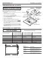
RVDD330R / CRVDD330R 30" w/ remote control VIDV500 Interior or VEDV900 Exterior
RVDD336R / CRVDD336R 36" w/ remote control VIDV500 Interior or VEDV900 Exterior
RVDD345R / CRVDD345R 45" w/ remote control VIDV500 Interior, VEDV900 Exterior, or VEDV1200 Exterior
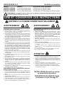
WARNING - To reduce the risk of burns or ignition of clothing by reaching across burners, the downdraft remote control MUST
be mounted in the countertop - at least 4" from the burners. See "INSTALL COOKTOP" section on page 8.
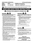
READ AND SAVE THESE INSTRUCTIONS
! INTENDED FOR DOMESTIC COOKING ONLY !
WARNING
WARNING
TO REDUCE THE RISK OF FIRE, ELECTRIC SHOCK, OR INJURY TO PERSONS, OBSERVE THE FOLLOWING:
TO REDUCE THE RISK OF INJURY TO PERSONS IN THE
EVENT OF A RANGE TOP GREASE FIRE, OBSERVE THE
FOLLOWINGa:
1. Use this unit only in the manner intended by the manufacturer.
If you have questions, contact the manufacturer at the address
or telephone number in the warranty.
2. Before servicing or cleaning unit, switch power off at service
panel and lock the service disconnecting means to prevent
power from being switched on accidentally. When the service
disconnecting means cannot be locked, securely fasten a
prominent warning device, such as a tag, to the service panel.
3. Installation work and electrical wiring must be done by a
qualified person(s) in accordance with all applicable codes
and standards, including fire-rated construction codes and
standards.
4. Sufficient air is needed for proper combustion and exhausting
of gases through the flue (chimney) of fuel burning equipment to prevent backdrafting. Follow the heating equipment
manufacturer’s guideline and safety standards such as those
published by the National Fire Protection Association (NFPA),
and the American Society for Heating, Refrigeration and Air
Conditioning Engineers (ASHRAE), and the local code authorities.
5. When cutting or drilling into wall or ceiling, do not damage
electrical wiring and other hidden utilities.
6. Ducted fans must always be vented to the outdoors.
7. To reduce the risk of fire, use only metal ductwork.
8. Do not install this product with the activating switch directly
behind a burner or element. Minimum distance between the
switch and the edge of the cook top or range top should be 4
inches.
9. Loose-fitting or hanging clothing should never be worn when
operating this appliance. They may be ignited by burners/
elements on cooktop.
10. Children should not be left alone or unattended in the area
where this appliance is in use.
11. This unit must be grounded.
1. SMOTHER FLAMES with a close-fitting lid, cookie sheet,
or metal tray, then turn off the burner. BE CAREFUL TO PREVENT BURNS. If the flames do not go out immediately,
EVACUATE AND CALL THE FIRE DEPARTMENT.
2. NEVER PICK UP A FLAMING PAN - You may be burned.
3. DO NOT USE WATER, including wet dishcloths or towels
- a violent steam explosion will result.
4. Use an extinguisher ONLY if:
A. You know you have a Class ABC extinguisher, and you already know how to operate it.
B. The fire is small and contained in the area where it started.
C. The fire department is being called.
D. You can fight the fire with your back to an exit.
a
Based on “Kitchen Firesafety Tips” published by NFPA.
CAUTION
!
1. For general ventilating use only. Do not use to exhaust hazardous or explosive materials and vapors.
2. To avoid motor bearing damage and noisy and/or unbalanced
impellers, keep drywall spray, construction dust, etc. off power
unit.
3. Clean filters and grease-laden surfaces frequently.
4. Do not repair or replace any part of this appliance unless
specifically recommended in this manual. All other servicing
should be done by a qualified technician.
5. Please read specification label on product for further information and requirements.
TO REDUCE THE RISK OF A RANGE TOP GREASE FIRE:
a) Never leave surface units unattended at high settings. Boilovers cause smoking and greasy spillovers that may ignite. Heat oils slowly on low or medium settings.
b) Always turn hood ON when cooking at high heat or when
cooking flaming foods.
c) Clean ventilating fans frequently. Grease should not be allowed to accumulate on fan or filter.
d) Use proper pan size. Always use cookware appropriate for the size of the surface element.
INSTALLER:
Save this manual for Electrical
Inspector and Homeowner to use.
HOMEOWNER:
Use and Care Information on Page 11.
1
VIKING RANGE, LLC
Downdraft Ventilators
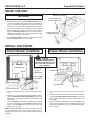
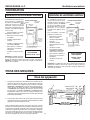
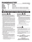
PLANNING
Interior Blower Installation
This downdraft blower system is
designed to be used to exhaust
airborne contaminants when
cooking with a variety of gas
or electric cooktops. It can be
mounted in island, peninsula,
or conventional wall locations.
This unit can be easily installed
following these basic steps:
•
Cut out the countertop
opening.
•
Mount the unit in the cabinet.
•
Install the Model VIDV500
Interior Blower
•
•
Connect the ductwork and
electrical.
Install the cooktop.
Note: the high level of air flow
of this appliance may effect the
gas flame on some types of gas
cooktops. This is NORMAL and
will cause no harm, but can be
corrected by lowering the speed
of the blower.
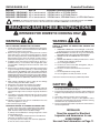
Exterior Blower Installation
This downdraft blower system
is designed to be used to exhaust airborne contaminants
when cooking with a variety
of gas or electric cooktops.
It can be mounted in island,
peninsula, or conventional wall
locations.
TYPICAL INSTALLATION
COUNTER
TOP
CHIMNEY TOP
COOK TOP
AIR
VENT
GEAR
MOTOR
COVER
This unit can be easily installed
following these basic steps:
BLOWER
BOX
120 VAC
GROUNDED
OUTLET
3-1/4" X 10"
DUCT CONNECTOR
•
Cut out the countertop
opening.
•
Mount the unit in the
cabinet.
•
Install 10" round discharge plate
•
ELECTRICAL
SPECIFICATIONS
120 VAC • 60 Hz • 4.0 A
Install Model VEDV900 or
VEDV1200 (DIPR151RSS
only) External Blower
•
Connect the ductwork
and electrical.
•
Install the cooktop.
TYPICAL INSTALLATION
COUNTER TOP
CHIMNEY TOP
COOK TOP
GEARMOTOR
COVER
AIR
VENT
10" ROUND
DISCHARGE
PLATE
120 VAC
GROUNDED
OUTLET
10" ROUND DUCTWORK
ELECTRICAL
SPECIFICATIONS
120 VAC • 60 Hz • 6.0 A (max.)
Note: the high level of air flow of this appliance may effect the
gas flame on some types of gas cooktops. This is NORMAL and
will cause no harm, but can be corrected by lowering the speed
of the blower.
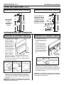
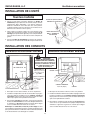
TAKE MEASUREMENTS
All Units
1. Refer to the cooktop installation instructions for dimensions of
cooktop, countertop cut-out, and cabinet requirements. The
Model RVDD330R / CRVDD330R will fit in most 30" wide
cabinets, the Model RVDD336R / CRVDD336R will fit in most
36" wide cabinets, and the Model RVDD345R / CRVDD345R
will fit most 45" wide cabinets. However, it is recommended
that oversized cabinets be used for easier installation.
2. Cooktop depth can vary greatly from one to another. This may
cause the fit of these two appliances to be rather tight.
Pay special attention to the areas of potential interference highlighted above. A countertop with (A) a raised lip and/or (B) a
backsplash may not allow enough flat countertop for a proper
installation. Note that 2" of flat countertop is required behind
cooktop and that 1-3/4" is necessary between the back edge of
the cooktop and the inside of cabinet back.
2
VIKING RANGE, LLC
Downdraft Ventilators
TAKE MEASUREMENTS (CONTINUED)
Interior Blower Installation
Exterior Blower Installation
SIDE VIEW
OF DOWNDRAFT
WITH
VIDV500
INTERIOR
BLOWER
SIDE VIEW
OF DOWNDRAFT
WITH
10" ROUND ELBOW
(for connection
to VEDV900
or VEDV1200
(DIPR150RSS only))
VIDV500
INTERIOR
BLOWER
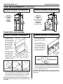
PLAN THE DUCTWORK
Interior Blower Installation
1. The interior downdraft blower system is
designed for use with
3-1/4" x 10" ductwork
(can be transitioned
to 6" round). Three
different discharge
directions are available with side-toside adjustment for
accurate alignment of
ductwork.
Exterior Blower Installation
LEFT
DISCHARGE
1. The exterior downdraft
blower system is designed
for use with 10" round ductwork.
2. For best performance:
Plan ducting which has the
shortest length of ductwork
and a minimum number of
elbows. Check location of
floor joists, wall studs, electrical wiring or plumbing for
possible interference.
2. For best performance:
RIGHT
Choose the ducting
DISCHARGE
option which allows
the shortest length
DOWN DISCHARGE
of ductwork and a
minimum number of elbows and transitions. Check location
of floor joists, wall studs, electrical wiring or plumbing for
possible interference.
6" ROUND
ELBOW
EQUALS 6 FT. OF
STRAIGHT DUCT
3-1/4" X 10" TO 6" RD.
TRANSITION
EQUALS
2 FT. OF
STRAIGHT DUCT
10" ROUND
DISCHARGE
PLATE
10" ROUND
ELBOW
3-1/4" X 10"
90O ELBOW
3. The system will operate most efficiently when the ductwork
does not exceed 40 feet of equivalent duct. The illustration,
above, shows equivalent feet of a 10" round elbow. The number
of feet of straight duct plus the equivalent feet of elbows to be
used should equal 40 feet or less.
EQUALS 8 FT. OF
STRAIGHT DUCT
NOTE: The equivalent feet of various roof and wall caps has
been taken into consideration. Do not include them in this
calculation.
3. The system will operate most efficiently when the ductwork
does not exceed 40 feet of equivalent duct. The chart, above,
shows equivalent feet of elbows and transitions. The number
of feet of straight duct plus the equivalent feet of transitions
and/or elbows to be used should equal 40 feet or less.
NOTE: The equivalent feet of various roof and wall caps has
been taken into consideration. Do not include them in this
calculation.
EQUALS 6 FT. OF
STRAIGHT DUCT
3
VIKING RANGE, LLC
Downdraft Ventilators
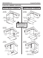
PLAN THE CABINET CUTOUTS
Interior Blower Installation
Exterior Blower Installation
LEFT SIDE
DISCHARGE
LEFT SIDE
DISCHARGE
241
/8"
19¾
CENTER LINE
OF COUNTER
CUTOUT
CENTER
LINES OF
DUCT CUTOUT
10¼" x 3½"
CUTOUT
(TYP.)
CENTER LINE
OF COUNTER
CUTOUT
CENTER LINES
OF DUCT
CUTOUT
10" ROUND
CUTOUT
(TYP.)
!
5½"
"
CAUTION:
BEFORE CUTTING HOLE IN
CABINET FOR DUCTWORK,
check for interference with floor
joists, wall studs, electrical wiring, or plumbing.
RIGHT SIDE
DISCHARGE
10¼
"
RIGHT SIDE
DISCHARGE
16
3/8"
"
19¾
CENTER
LINES OF
DUCT
CUTOUT
CENTER LINE
OF COUNTER
CUTOUT
CENTER
LINES OF
DUCT
CUTOUT
CENTER LINE
OF COUNTER
CUTOUT
10¼" x 3½"
CUTOUT
(TYP.)
10" ROUND
CUTOUT
(TYP.)
"
5½"
10¼
BOTTOM
DISCHARGE
BOTTOM
DISCHARGE
"
3½
CENTER LINE
OF COUNTER
CUTOUT
o
1" t
"
8"
CENTER LINE
OF DUCT CUTOUT
10" ROUND
DIA. CUTOUT
(TYP.)
5½"
10¼" x 3½"
CUTOUT
(TYP.)
2¾
CENTER LINE
OF COUNTER
CUTOUT
"
10¼
¼"
4
CENTER
LINE
OF DUCT
CUTOUT
6
CENTER LINE
OF DUCT CUTOUT
(can be located within this area)
VIKING RANGE, LLC
Downdraft Ventilators
PLAN THE WIRING
Interior Blower Installation
Exterior Blower Installation
1. The Interior Downdraft Blower system draws 4 AMPS and
requires a 120 VAC, 60 Hz circuit.
1. The Exterior Downdraft Blower system draws 6 AMPS and
requires a 120 VAC, 60 Hz circuit.
2. The downdraft has a 2 ft. long power cord with a 3-pronged
plug. Plan to provide a grounded outlet in a location which will
allow the unit’s power cord to reach.
2. The downdraft has a 2 ft. long power cord with a 3-pronged
plug. Plan to provide a grounded outlet in a location which will
allow the unit’s power cord to reach.
IMPORTANT - LOCATION OF ELECTRICAL OUTLET:
If Model RVDD330R / CRVDD330R is being installed in a
30" wide cabinet...
or Model RVDD336R / CRVDD336R is being installed
in a 36" wide cabinet...
or Model RVDD345R / CRVDD345R is being installed
in a 45" wide cabinet...
...the outlet cannot be located on the back wall
of cabinet.
In these cases, the width of the downdraft covers nearly the
entire width of the back wall of the cabinet. So you must
either:
• mount the electrical box to a side wall or cabinet floor
- at least 12 inches from the back wall.
• mount the electrical box to a wall stud behind the
cabinet - where it will not be covered by the downdraft
Then provide a clearance hole in the back wall of the
cabinet.
PLEASE NOTE: External blowers must be hard-wired using locallysupplied wire and connected to the downdraft plug (included).
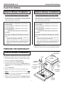
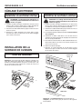
PREPARE THE DOWNDRAFT
Interior Blower Installation
3¼" X 10"
DISCHARGE
The downdraft is shipped without a blower. Purchase a Model
VIDV500 Interior Blower and mount it to the downdraft as follows:
NUTS
BLOWER
1. Place the downdraft on its back on a table of flat work surface.
2. Remove the 4 nuts and 2 clamp channels.
3. Remove 2 screws and the gear motor cover.
CLAMP
CHANNELS
4. Carefully position the blower under the bottom flange of the
downdraft with the 3¼" x 10" discharge pointed in the desired
direction.
SCREWS
5. Connect motor plug.
6. Replace the gear motor cover and 2 sheet metal screws.
GEARMOTOR
COVER
COVER
PLATE
MOTOR
PLUG
ADDITIONAL
SCREWS
7. Replace the 2 clamp channels and start the 4 nuts, do not
tighten.
8. Slide blower left of right to desired position. Use cover plate
(supplied) to close up any open space.
9. Tighten 4 nuts to secure top of blower. Use additional screws
(supplied) through bottom flange to secure bottom in blower.
5
BOTTOM
FLANGE
VIKING RANGE, LLC
Downdraft Ventilators
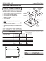
PREPARE THE DOWNDRAFT
Exterior Blower Installation
NUTS
The downdraft is shipped without a blower. Purchase a Model
VEDV900 Exterior Blower and mount the 10" discharge plate
to the downdraft as follows:
10" ROUND
DISCHARGE
PLATE
MOTOR
PLUG
CLAMP
CHANNELS
1. Place the downdraft on its back on a table of flat work surface.
2. Remove the 4 nuts and 2 clamp channels.
SCREWS
3. Remove 2 screws and the gear motor cover.
4. Carefully position the10" discharge plate under the bottom
flange of the downdraft.
COVER
PLATE
GEARMOTOR
COVER
5. Connect motor plug.
ADDITIONAL
SCREWS
6. Replace the gear motor cover and 2 sheet metal screws.
7. Replace the 2 clamp channels and start the 4 nuts, do not
tighten.
8. Slide blower left of right to desired position. Use cover plate
(supplied) to close up any open space.
9. Tighten 4 nuts to secure top of blower. Use additional screws
(supplied) through bottom flange to secure bottom of discharge
plate.
BOTTOM
FLANGE
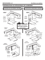
CUT COUNTERTOP OPENING
All Units
1. Measure and cut the countertop opening for your width of
cooktop and downdraft.
30" RVGC3305B
Cooktop Width & Model
30" RVEC3305B
30" CRVGC3305B
30" CRVEC3305B
For use with Downdraft Models
RVDD330R
CRVDD330R
36" RVGC3365B
45" RVEC3456B
36" RVEC3365B
45" CRVEC3456B
36" CRVGC3365B
36" CRVEC3365B
RVDD336R
CRVDD336R
RVDD345R
CRVDD345R
Cutout Dimensions
34-7/8"
20-5/8"
33"
2-1/4"
15/16"
15/16"
42-7/8"
20-5/8"
42"
2-1/4"
7/16"
7/16"
A
B
C
D
E
F
29-1/8"
20-5/8"
27"
2-1/4"
1-1/16"
1-1/16"
F
E
C
D
B
A
6
BLOWER MODEL
DIMENSIONS
VIDV500
18.25" x 18.214" x 7.569"
VEDV900
28.25" x 24.75" x 7.16"
VEDV1200
22" x 30.828" x 12.724"
VIKING RANGE, LLC
Downdraft Ventilators
MOUNT THE UNIT
MOUNTING SCREWS
All Units
LEVELING BRACKET FLANGE FACING OUT
1. Set downdraft into opening. Extend leveling brackets to floor
of cabinet so downdraft sits straight. (Note: Leveling brackets
can be removed and re-attached in other positions. Bottom
flange may have to face inward in tight cabinet installations.)
2. Secure the downdraft to the countertop as follows: Hold the
downdraft against the back of countertop cut-out and tightening the two mounting screws (one on each end of unit) on
underside of countertop. Use a wood shim between screw
and underside of granite countertops.
LEVELING BRACKET FLANGE FACING IN
3. Screw leveling brackets to bottom of cabinet. Tighten screws
holding leveling bracket to unit on each side.
INSTALL DUCTWORK
Interior Blower Installation
Exterior Blower Installation
!
CAUTION:
BEFORE CUTTING HOLE IN
CABINET FOR DUCTWORK,
check for interference with floor
joists, wall studs, electrical wiring, or plumbing.
BLOWER
COLLAR
SCREWS
3-1/4" X 10"
TO 6" RD.
TRANSITION
ELBOW
6" RD. ELBOW
& DUCTWORK
10" ROUND DUCT
ELBOW
1. Cut hole in cabinet as well as holes in wall or floor as necessary.
1. Cut hole in cabinet as well as holes in wall or floor as necessary.
2. Mount the roof or wall cap and work back towards the cabinet,
attaching all ductwork, elbows and transitions as previously
planned. Tape all ductwork connections to make them secure
and air tight.
2. Mount the exterior blower and work back towards the cabinet,
attaching all ductwork, elbows and transitions as previously
planned. Tape all ductwork connections to make them secure
and air tight.
3. Connect ductwork (and transition, if required) to downdraft.
If necessary, LOOSEN nuts and screws that hold the blower
in place, and slide blower left or right to meet ductwork. Retighten screws and nuts.
3. Connect ductwork to downdraft. If necessary, LOOSEN nuts
and screws that hold remote blower adapter plate in place, and
slide outlet assembly left or right to meet ductwork. Re-tighten
screws and nuts.
Note: A 3-1/4" x 10" collar is provided for installers who prefer
to rivet the ductwork to the unit. This will allow blower to be removed and replaced easily in service situations without disturbing
ductwork.
7
VIKING RANGE, LLC
Downdraft Ventilators
INSTALL ELECTRICAL WIRING
Interior Blower Installation
Exterior Blower Installation
!
!
CAUTION: All electrical wiring should be done
by a qualified person(s) in accordance with all
applicable codes and standards.
CAUTION: All electrical wiring should be done
by a qualified person(s) in accordance with all
applicable codes and standards.
1. Mount a standard wiring box, with 3-pronged receptacle, inside
the cabinet. Make sure the downdraft's power cord can easily
reach it.
1. Mount a standard wiring box, with 3-pronged grounded receptacle, inside the kitchen cabinet. Make sure the downdraft's
power cord can easily reach it.
2. Run appropriate power cable into cabinet and connect it to
receptacle.
2. Run appropriate power cabinet into cabinet and connect it to
electrical box and receptacle.
3. Plug the downdraft's power cord into the outlet. Make sure that
the power cord is routed away from the heat generated by the
cooktop.
3. Exterior blower may not exceed 6.0 Amp rating.
4. Run 2-wire plus ground power cable from the remote blower
to wiring box on 10" round discharge plate.
5. Connect downdraft wiring to power cable from remote blower.
Wire black to black, white to white, and green to green or bare
wire.
6. Replace wiring box cover.
7. Plug the downdraft's power cord into outlet. Make sure that
the power cord is routed away from the heat generated by the
cooktop.
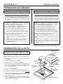
INSTALL COOKTOP
All Units
"R" MODEL
DOWNDRAFT
1. Align the cooktop with the downdraft and fasten cooktop in
place.
Note: Accurate alignment of cooktop and downdraft is necessary
to ensure that there is no interference when air vent is raised and
lowered. There should be a gap of 1/32" - 1/16" between the back
of the cooktop and the front of the downdraft cover.
REMOTE
CONTROL
COUNTERTOP
Note:
The downdraft remote control must be mounted into the countertop, at least 4" from cook top or range top edge.
8
VIKING RANGE, LLC
Downdraft Ventilators
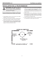
INSTALLATION OF REMOTE CONTROL SWITCH
WARNING: To reduce the risk of burns or ignition
of clothing by reaching across burners, the remote
control must be mounted at least 4" from cook top
or range top edge.
3. Remove the control from the plastic bag. Remove the paper
from the adhesive back of the control, line the control up with
the three holes and position the control so it is parallel with
the front of the counter top. Press down firmly for 60 seconds.
Keep in mind you do not want to place the control where it
will be in the way for cooking, or where hot pans could be
set, or hot liquids spilled on the control.
4. Remove the two nylon thumbnuts from the plastic bag and
thread onto the two studs on the control from below the counter top. Hand tighten only. The thumbnuts just need to be
snugged by hand. They are there to hold the control in place
until the adhesive sets up.
1. Using the template below, lay out the 3-hole pattern on the
counter top. Mark the centers of the three holes to be drilled.
5. Remove cable from the plastic bag and plug into back of control
from below counter top. Route cable through cabinet to lower
right hand corner of downdraft. Plug other end of cable into
the downdraft unit. (Receptacle hole for cabinet is on the lower
right hand side of the downdraft.)
2. Carefully drill the three holes through the counter top. Be careful
not to damage or chip the counter top surface when drilling
the holes.
6. Stuff excess cable out of the way and secure the cable so it
is not damaged from items stored in the cabinet.
TOP EDGE
1/4" DIA.
HOLE
1/4" DIA.
HOLE
1" DIA.
HOLE
CUT OUT ON DOTTED LINE
9
VIKING RANGE, LLC
Downdraft Ventilators
This page has been
left blank intentionally.
BACKSIDE OF
REMOTE SWITCH
TEMPLATE
10
VIKING RANGE, LLC
Downdraft Ventilators
OPERATION
UP / DOWN����Raises and
lowers vent.
Turns blower ON when vent is UP and
OFF when vent is DOWN.
All Units
DELAY�����������Allows blower to run for 10 min. after button
is pressed. Delay is activated by holding
down any speed control button until the LED
indicator flashes. Blower will run for 10 min.
- then shut OFF. VENT WILL NOT LOWER.
You must press UP / DOWN to lower vent.
When DELAY is activated, the speed level
light will blink.
REMOTE CONTROL
FOR MODELS
RVDD330R
RVDD336R
RVDD345R
CRVDD330R
CRVDD336R
CRVDD345R
BLOWER SPEEDS������Blower operates at 4 different speed
levels. Press button ONCE to turn
blower ON to desired speed. Press
button AGAIN to turn blower OFF.
FILTER LIGHT������������Comes ON after 30 hours of operation to remind you to clean filters.
Press button to reset.
USE AND CARE
Always turn the downdraft blower
on before you begin cooking to
establish an air flow in the kitchen.
Let the blower run for a few minutes
to clean the air after you turn the
cooktop off.This will keep the whole
kitchen cleaner and brighter. The
activating switch is pressed and
the air vent rises.
All Units
WARNING: Always disconnect electric power
supply before cleaning and/or servicing unit.
Wash the 2 aluminum/stainless
steel grease filters in a mild detergent solution or a dishwasher.
Remove them from the air vent
by grasping the tab at the top of
each filter.
Servicing
It may be necessary to remove the downdraft blower system from
the cabinet in order to service components such as the blower
motor or air vent mechanism.
Cleaning
Use a mild detergent suitable for painted surfaces. DO NOT USE
ABRASIVE CLOTH, STEEL WOOL PADS, OR SCOURING POWDERS. Vacuum blower to clean. Do not immerse blower in water.
Disconnect power to the cooktop and remove it first. Reverse the
steps under “MOUNT THE UNIT” to remove the downdraft from
the cabinet.
11
BUILT-IN REAR DOWNDRAFT WARRANTY
THREE YEAR FULL WARRANTY
Built-in downdraft ventilators, all of their component parts and accessories, except as detailed below*, are warranted to be free
from defective materials or workmanship in normal household use for a period of thirty-six (36) months from the date of original
retail purchase. Viking Range, LLC, warrantor, agrees to repair or replace, at its option, any part which fails or is found to be
defective during the warranty period. For the purpose of this warranty, normal household use shall not include use of this downdraft
ventilator with a cooking unit that has a grill. The Viking warranty does not cover any additional ventilation products not provided
by Viking used in conjunction with Viking downdrafts or ventilator kits. This includes, but is not limited to, such devices as booster
fans or in-line blowers. Any malfunction caused to Viking ventilation products as a direct result of the use of such equipment is
not covered under the Viking warranty.
Painted and decorative items are warranted to free from defective materials or workmanship for a period of ninety (90) days from
the date of original retail purchase. ANY DEFECTS MUST BE REPORTED TO THE SELLING DEALER WITHIN NINETY (90)
DAYS FROM DATE OF ORIGINAL RETAIL PURCHASE.
FIVE YEAR LIMITED WARRANTY
Any ventilator motor which fails due to defective materials or workmanship in normal household use during the second through
the fifth year from the date of original retail purchase will be repaired or replaced, free of charge for the part itself, with the owner
paying all other costs, including labor.
This warranty extends to the original purchaser of the product warranted hereunder and to each transferee owner of the product
during the term of the warranty.
This warranty shall apply to products purchased and located in the United States and Canada. Products must be purchased in
the country where service is requested. Warranty labor shall be performed by an authorized Viking Range, LLC service agency
or representative. Warranty shall not apply to damage resulting from abuse, accident, natural disaster, loss of electrical power to
the product for any reason, alteration, outdoor use, improper installation, improper operation or repair or service to the product by
anyone other than an authorized Viking Range, LLC service agency or representative. This warranty does not apply to commercial
usage. Warrantor is not responsible for consequential or incidental damage whether arising out of breach of warranty, breach of
contract, or otherwise. Some jurisdictions do not allow the exclusion or limitation of incidental or consequential damages, so the
above limitation or exclusion may not apply to you.
Owner shall be responsible for proper installation, providing normal care and maintenance, providing proof of purchase upon
request, and making the appliance reasonably accessible for service. If the product or one of its component parts contains a
defect or malfunction during the warranty period, after a reasonable number of attempts by the warrantor to remedy the defects or
malfunctions, the owner is entitled to either a refund or replacement of the product or its component part or parts. Replacement of
a component part includes its free installation. Warrantor’s liability on any claim of any kind, with respect to the goods or services
covered hereunder, shall in no case exceed the price of the goods or service or part there of which gives rise to the claim.
WARRANTY SERVICE: Under the terms of this warranty, service must be performed by a factory authorized Viking Range,
LLC service agent or representative. Service will be provided during normal business hours, and labor performed at overtime or
premium rates shall not be covered by this warranty. To obtain warranty service, contact the dealer from whom the product was
purchased, an authorized Viking Range, LLC service agent, or Viking Range, LLC. Provide model and serial number and date
of original purchase. For the name of your nearest authorized Viking Range, LLC service agency, call the dealer from whom the
product was purchased or Viking Range, LLC. IMPORTANT: Retain proof of original purchase to establish warranty period.
The return of the Owner Registration Card is not a condition of warranty coverage. You, however, should return the Owner
Registration Card so that Viking Range, LLC can contact you should any question of safety arise which could affect you.
Any implied warranties of merchantability and fitness applicable to the above described ventilator motor are limited in duration
to the period of coverage of the applicable express written limited warranties set forth above. Some jurisdictions do not allow
limitations on how long an implied warranty lasts, so the above limitation may not apply to you. This warranty gives you specific
rights, and you may also have other rights which may vary from jurisdiction to jurisdiction.
VIKING RANGE, LLC
111 Front Street
Greenwood, Mississippi 38930 USA
(662) 455-1200
Specifications subject to change without notice.
For more product information, call 1-888-845-4641, or visit the
web site at vikingrange.com in the U.S. or brigade.ca in Canada.
F20126
99044906C
VIKING RANGE, LLC
MODÈLE
RVDD330R / CRVDD330R
RVDD336R / CRVDD336R
RVDD345R / CRVDD345R
Ventilateurs encastrées
LARGEUR
VENTILATEUR (vendu séparément)
76,2 cm (30 po) télécommande
91,4 cm (36 po) télécommande
114,3 cm (45 po) télécommande
VIDV500 intérieur ou VEDV900 extérieur
VIDV500 intérieur ou VEDV900 extérieur
VIDV500 intérieur, VEDV900 extérieur, ou VEDV1200 extérieur
AVERTISSEMENT – Pour réduire les risques de brûlure ou que des vêtements s’enflamment en traversant les brûleurs, une hotte de
modèle la télécommande DOIT être installée à au moins 10 cm (4 po) des brûleurs de la cuisinière. Consultez les instructions à la page
20 "INSTALLATION DE LA SURFACE DE CUISSON".
LIRE ET CONSERVER CES INSTRUCTIONS
! DESTINÉ À LA CUISINE DOMESTIQUE SEULEMENT !
AVERTISSEMENT
AVERTISSEMENT
AFIN DE DIMINUER LES RISQUES D’INCENDIE, D’ÉLECTROCUTION OU
DE BLESSURES, SUIVEZ CES DIRECTIVES:
1. Utilisez ce produit en suivant les recommandations du manufacturier.
Pour toute question, contactez le manufacturier à l’adresse ou au
numéro de téléphone indiqués dans la garantie.
2. Avant de réparer ou de nettoyer cette hotte, coupez le courant au panneau d’alimentation et verrouillez-en l’accès afin d’éviter que le courant
ne soit accidentellement remis en fonction. S’il vous est impossible
de le verrouiller, apposez un indicateur voyant sur le panneau comme,
par exemple, une étiquette de couleur vive.
3. L’installation de la hotte ainsi que le câblage électrique doivent être
effectués par une ou des personnes compétentes selon les normes et
les règles en vigueur, incluant celles qui régissent la prévention des
incendies.
4. Une circulation d’air efficace est requise afin d’assurer la combustion
et l’évacuation complète des gaz par le tuyau d’évacuation (cheminée) des équipements à combustion et pour prévenir les retours
d’air. Conformez-vous aux normes et mesures de sécurité pour les
manufacturiers d’appareils de chauffage publiées par la “National Fire
Protection Association (NFPA)” et par la “American Society for Heating,
Refregiration and Air Conditioning Engineers (ASHRAE)”, ainsi qu’aux
normes en vigueur dans votre région.
5. Lorsque vous coupez ou percez un mur ou un plafond, prenez garde
d’endommager les fils électriques ou autres installations qui pourraient
y être dissimulés.
6. Les installations ventilées doivent toujours être reliées à des conduits
rejetant l’air à l’extérieur.
7. Afin de diminuer les risques d’incendie, n’utilisez que des conduits
de ventilation en métal.
8. Ne pas installer ce produit en plaçant le commutateur directement
derrière un brûleur ou un élément. La distance entre le switch et le
bord de la cuisson ou de la gamme haut devrait être d'au moins 10
cm (4 po).
9. Ne pas porter de vêtements amples ou accrochants lors de l’utilisation
de cet appareil. Ils pourraient s’enflammer au contact de l’un des
brûleurs ou des éléments de la cuisinière.
10. Ne jamais laisser un enfant seul ou sans surveillance à proximité de
cet appareil lors de son utilisation.
11. Ce ventilateur doit être relié à une mise à la terre.
AFIN DE DIMINUER LES RISQUES D’INCENDIE POUVANT SE DÉCLENCHER SUR LA SURFACE DE CUISSON:
1. Ne jamais laisser sans surveillance des unités de surface réglées à
feu vif. En plus de générer de la fumée, les débordements de graisse
peuvent prendre feu. Chauffer les huiles lentement à feu doux ou
moyen.
2. Toujours mettre en marche la hotte durant la cuisson à feu vif ou la
cuisson d’aliments à flamber.
3. Nettoyer régulièrement les ventilateurs d’aération. On ne doit tolérer
aucune accumulation de graisse sur le ventilateur ou sur le filtre.
4. Utiliser une casserole de grosseur appropriée. Toujours utiliser une
batterie de cuisine proportionnelle à l’élément de surface.
AFIN DE DIMINUER LES RISQUES DE BLESSURES POUVANT SURVENIR LORSQU’UN FEU SE DÉCLENCHE SUR LA SURFACE DE CUISSON,
SUIVEZ CES DIRECTIVES:
1. ÉTOUFFEZ LES FLAMMES avec un couvercle hermétique, une tôle à
biscuits ou un plateau en métal puis éteignez la cuisinière. PRENEZ
GARDE AUX BRÛLURES. Si vous ne parvenez pas à éteindre immédiatement les flammes, ÉVACUEZ LES LIEUX ET CONTACTEZ VOTRE
POSTE LOCAL DE LUTTE CONTRE LES INCENDIES.
2. NE VOUS EMPAREZ JAMAIS D’UN PLAT QUI S’EST ENFLAMMÉ – Vous
risqueriez de vous brûler.
3. N’UTILISEZ JAMAIS D’EAU, incluant les linges à vaisselles ou serviettes mouillés car cela peut provoquer une violente explosion de
vapeur.
4. Utilisez un extincteur SEULEMENT si:
A. Il s’agit d’un extincteur de classe ABC et que vous savez comment vous
en servir.
B. Il s’agit d’un petit feu qui ne se propage pas ailleurs que sur la
cuisinière. C.
Vous avez appelé votre poste local de lutte
contre les incendies.
D. Vous pouvez combattre le feu tout en ayant accès à une sortie.
* Basé sur “Kitchen Fire Safety Tips” édité par NFPA.
ATTENTION
!
1. Pour ventilation générale seulement. Ne l´utilisez pas pour évacuer
les vapeurs ou matériaux dangereux ou que peuvent exploser.
2. Pour éviter d´endommager les coussinets du moteur et des turbines
bruyantes et/ou mal équilibrées, assurez que l´unité motrice est
exempte de poussière provenant des murs en pierres sèches et la
construction.
3. Nettoyer souvent les filtres et les surfaces graisseuses.
4. Ne réparer ou remplacer que les pièces recommandées dans ce manuel.
Toute autre réparation doit être confiée à un technicien qualifié.
5. Veuillez lire l´étiquette de spécifications sur le produit pour d´autres
renseignements et exigences.
INSTALLATEUR: Remetez ce manuel
au protpriétaire de maison.
PROPRIÉTAIRE DE MAISON: Mode
d’utilisation et soin à la page 23.
13
VIKING RANGE, LLC
Ventilateurs encastrées
PRÉPARATION
Installation du ventilateur extérieur
Installation du ventilateur intérieur
Ce ventilateur encastré est conçu
pour évacuer les contaminants
de l’air lors de l’utilisation d’une
surface de cuisson au gaz ou
électrique. Il peut être installé
dans un îlot, une péninsule ou un
comptoir conventionnel appuyé
contre un mur.
• Pour l’installation, procédez
simplement comme suit :
•
Découpez l’ouverture dans
le comptoir.
•
Installez l’appareil dans
l’armoire.
•
Installez le ventilateur intérieur modèle VIDV500.
•
Raccordez les conduits et
effectuez les connexions
électriques.
•
Installez la surface de cuisson.
Ce ventilateur encastré est
conçu pour évacuer les contaminants de l’air lors de l’utilisation d’une surface de cuisson
au gaz ou électrique. Il peut
être installé dans un îlot, une
péninsule ou un comptoir
conventionnel appuyé contre
un mur.
Pour l’installation, procédez
simplement comme suit :
INSTALLATION TYPE
COMPTOIR
SURFACE DE
CUISSON
COUVERCLE
DU MOTEUR
BOUCHE DE
CHEMINÉE
CONDUIT
D’AÉRATION
BOÎTIER DU
VENTILATEUR
•
PRISE 120
VCA AVEC
MISE À LA
TERRE
•
•
RACCORD DE CONDUIT 8,3 cm X
25,4 cm (3-1/4 po X 10 po)
•
SPÉCIFICATIONS
ÉLECTRIQUES
Découpez l’ouverture
dans le comptoir.
Installez l’appareil dans
l’armoire.
Installez la plaque
d’évacuation de 25,4 cm
(10 po)
Installez le ventilateur extérieur modèle
VEDV900 ou VEDV1200
(DIPR151RSS seulement)
•
120 VCA • 60 Hz • 4,0 A
Remarque : Le débit d’air élevé
de cet appareil peut affecter la
flamme de certaines surfaces de cuisson au gaz. Cet effet est
NORMAL et inoffensif, mais il peut être corrigé en réduisant la
vitesse de la soufflerie.
•
Raccordez les conduits et
effectuez les connexions
électriques.
Installez la surface de cuisson.
TYPICAL INSTALLATION
COMPTOIR
SURFACE DE
CUISSON
COUVERCLE
DU MOTEUR
CONDUIT
D’AÉRATION
CONDUIT
ROND DE
25,4 cm (10
po)
PRISE 120
VCA AVEC
MISE À LA
TERRE
PLAQUE D’ÉVACUATION DE
25,4 cm (10 po)
SPÉCIFICATIONS
ÉLECTRIQUES
120 VCA • 60 Hz •
6,0 A (max.)
Remarque : Le débit d’air élevé de cet appareil peut affecter la
flamme de certaines surfaces de cuisson au gaz. Cet effet est
NORMAL et inoffensif, mais il peut être corrigé en réduisant la
vitesse de la soufflerie.
PRISE DES MESURES
Tous les appareils
1. Consultez les instructions d’installation pour connaître les dimensions de la surface de cuisson, du découpage à effectuer
dans le comptoir et les exigences pour l’armoire. Le modèle
RVDD330R / CRVDD330R s’insèrent dans la plupart des armoires de 76,2 cm (30 po) de largeur, le modèle RVDD336R
/ CRVDD336R dans la plupart des armoires de 91,4 cm (36
po) de largeur, et le modèle RVDD345R / CRVDD345R dans
la plupart des armoires de 114,3 cm (45 po) de largeur. Il est
cependant recommandé d’utiliser des armoires plus grandes
pour faciliter l’installation.
44,5 mm (1¾ po)
50,8 mm (2 po)
COMPTIOR
SURFACE DE
CUISSION
VENTILATEUR
ENCASTRÉS
2. La profondeur des surfaces de cuisson peut varier beaucoup
d’un modèle à l’autre. Il est possible que l’installation des deux
appareils soit particulièrement serrée.
Faites particulièrement attention aux points encerclés ci-contre
pouvant nuire éventuellement. Un comptoir à rebord surélevé (A)
ou à dosseret arrondi (B) risque de ne pas offrir une surface plate
suffisamment grande pour permettre une installation adéquate.
Une surface plate de 5 cm (2 po) est nécessaire derrière la plaque
de cuisson et une distance de 4,4 cm (1-3/4 po) est requise entre
l’arrière de la plaque de cuisson et le fond de l’armoire.
BOUCHE DE
CHEMINÉE
AVANT AU DOS
L'INTERIEUR DE LA ARMOIRE PROFONDEUR
14
VIKING RANGE, LLC
Ventilateurs encastrées
PRISE DES MESURES (SUITE)
Installation du ventilateur extérieur
Installation du ventilateur intérieur
5 cm (2 po)
5 cm (2 po)
2"
0,95 cm
1"po)
(3/8
7 16 " 8,2 cm (3
po)
11/4
34"
19,5 cm
11
(7 11/16 po)
VUE DE CÔTÉ
DE LA HOTTE
AVEC
VENTILATEUR
INTÉRIEUR
VIDV500
9,25CM
(3 5/8 po)
38"
12,7 cm
(5 po)
5"
VIDV500
VENTILATEUR
45,7 cm INTÉRIEUR
INTERNAL
(18 po)
VIDV500
BLOWER
2"
1"
7 mm
4 po)
(1/4
0,95 cm
(3/8 po)
19,5 11
cm
8,2 cm (3
(7 11/16
16po) 1/4 po)
1
1"
VUE DE CÔTÉ DE LA
HOTTE AVEC COUDE
ROND DE 25,4 cm (10
po) (pour connexion
au ventilateur extérieur
VEDV900 ou VEDV1200
(DIPR150RSS seulement))
"
5,4 cm
2
(2 81/8
1
po)
5"
29 16(29
74,6 cm
5/16 po)
FROM
DU COMPTOIR
COUNTERTOP
AU DESSOUS DU
TO BOÎTIER
BOTTOM
OF AIR BOX
7 "
34"
2 "
9,2 5cm
(3 5/8 po)
38"
5
29 "
8,1 cm
3
(3 3/16 po)
3 16 "
10"
ROUND
COUDE
ROND
DE 25,4 cm
ELBOW
18"
1"
7 mm
4 po)
(1/4
5,4 1cm
(2 1/8
8
po)
1
13 "
33,6 cm
4
(13 1/4 po)
4 cm
(1 9/169 po)
1 16 "
74,6 cm
16
(29FROM
5/16 po)
DU COMPTOIR
COUNTERTOP
AU DESSOUS DU
TOBOÎTIER
BOTTOM
OF AIR BOX
(10 po)
33,6 cm
(13 1/4
1
13po)4 "
SIDE VIEW
VIPR DOWNDRAFT VENTILATORS
PRÉPARATION DES CONDUITS
Installation du ventilateur intérieur
Installation du ventilateur extérieur
1. Le ventilateur encas- SORTIE
tré intérieur est conçu DROITE
pour des conduits
de 8,3 cm x 25,4 cm
(3-1/4 po x 10 po) (ou
transformés en conduits ronds de 15,3
cm/6 po). Il existe trois
directions possibles
pour la sortie avec
un ajustement latéral
pour un parfait alignement du conduit.
1. Le ventilateur encastré extérieur est conçu pour des
conduits ronds de 25,4 cm
(10 po).
2. Pour un rendement optimal : Choisissez pour les
conduits le trajet le plus
court possible avec un minimum de coudes. Assurezvous que les solives du
plancher, les montants des
murs, les câbles électriques
et les tuyaux de nuisent
pas.
SORTIE
2. Pour un rendement
GAUCHE
optimal : Choisissez
pour les conduits le
trajet le plus court posSORTIE INFÉRIEURE
sible avec un minimum
de coudes et de transitions. Assurez-vous que les solives
du plancher, les montants des murs, les câbles électriques
et les tuyaux de nuisent pas.
TRANSITION DE 8,3 cm X
ÉGALE UN CONDUIT
DROIT DE 61 CM (2 PI) 25,4 cm (3-1/4 po X 10 po)
À 15,3 cm (6 po) ROND.
ÉGALE UN
CONDUIT
DROIT DE
ÉGALE UN CONDUIT 61 CM
DROIT DE 183 CM (6 PI) (2 PI)
COUDE ROND
DE 25,4 cm
(10 po)
COUDE À 90° DE
8,3 cm X 25,4 cm
(3-1/4 po X 10 po)
ÉGALE UN CONDUIT
DROIT DE 183 CM
(6 PI)
3. L’évacuation est plus efficace lorsque les conduits ne
dépassent pas 12 m (40 pi) de longueur ou l’équivalent.
L’illustration ci-dessus indique l’équivalent en longueur des
coudes et des transitions. La longueur des conduits droits
plus l’équivalent pour les coudes et les transitions ne doit
pas excéder 12 m (40 pi).
ÉGALE UN CONDUIT
DROIT DE 244 CM (8 PI)
3. L’évacuation est plus efficace lorsque les conduits ne
dépassent pas 12 m (40 pi) de longueur ou l’équivalent.
L’illustration ci-dessus indique l’équivalent en longueur d’un
coude rond de 25,4 cm (10 po). La longueur des conduits
droits plus l’équivalent pour les coudes ne doit pas excéder
12 m (40 pi).
REMARQUE : L’équivalent en longueur pour les chapeaux
de toit et de mur a été pris en considération. Ne pas inclure
ces éléments dans votre calcul.
PLAQUE
D’ÉVACUATION
DE 25,4 cm
(10 po)
REMARQUE : L’équivalent en longueur pour les chapeaux
de toit et de mur a été pris en considération. Ne pas inclure
ces éléments dans votre calcul.
15
VIKING RANGE, LLC
Ventilateurs encastrées
PRÉPARATION DU DÉCOUPAGE DE L’ARMOIRE
Installation du ventilateur intérieur
Installation du ventilateur extérieur
SORTIE À
GAUCHE
SORTIE À
GAUCHE
61,2
41(/24
8" 1/8
p
LIGNES DE
CENTRE
DU DÉCOUCENTER
LINES
PAGE
POUR
OF DUCT
CONDUIT
CUTOUT
o)
LIGNES DE
CENTRE
CENTER
DU DÉCOULINES OF
PAGE POUR
DUCT CUTOUT
CONDUIT
50
(19 ,129c¾
3/4 m"
po)
c2m
CENTER
LIGNE
DELINE
CENTRE
OF
DUCOUNTER
DÉCOUPAGE
CUTOUT
DU
COMPTOIR
10¼"
x 3½"
TROU
(TYP.)
8,26CUTOUT
x 25,4 cm
(3¼ x (TYP.)
10 po)
TROU ROND
10" ROUND
(TYP.)
25,4
cmCUTOUT
(10 po)
(TYP.)
!
14 c
5m½("5 1/
2p
ATTENTION : AVANT
DE DÉCOUPER L’ARMOIRE POUR LES
CONDUITS, assurez-vous que les
solives du plancher, les montants des
murs, les câbles électriques et les
tuyaux de nuisent pas.
o)
SORTIE À
DROITE
LIGNE DE CENTRE
CENTER LINE
DU DÉCOUPAGE
OF COUNTER
DU COMPTOIR
CUTOUT
26 c
m
10(¼
10 1
" /
4 po
)
SORTIE À
DROITE
m
3,6
/8"c )
14613/8 po
50,2
(16
LIGNELINE
DE
CENTER
DU
OFCENTRE
COUNTER
DÉCOUPAGE
CUTOUT
DU COMPTOIR
cm
)
" o
93¾/4 p
(119
LIGNES DE
CENTER
CENTRE
LINES
OF
DU DÉCOUDUCT
PAGE POUR
CUTOUT
CONDUIT
LIGNE DE
CENTER
LINE
CENTRE
DU
OF
COUNTER
DÉCOUPAGE
CUTOUT
DU
COMPTOIR
10¼" x(TYP.)
3½"
TROU
CUTOUT
8,26
x 25,4 cm
(3¼(TYP.)
x 10 po)
/2
½
(5"1
m5
14 c
po)
/4
10" 1
10(¼
m
26 c
po)
LIGNES DE
CENTER
CENTRE
LINES
OF
DU DÉDUCT
COUPAGE
CUTOUT
POUR
CONDUIT
10" ROUND
TROU
CUTOUT
ROND
(TYP.)
(TYP.) 25,4
cm (10 po)
SORTIE
VERS LE BAS
SORTIE
VERS LE BAS
CENTER
LINE
LIGNE
DE CENTRE
COUNTER
DU OF
DÉCOUPAGE
CUTOUT
DU COMPTOIR
o) à
(1 p po)
cm8"
21,"5to cm (8
20,3
LIGNE
DE CENTRE
CENTER
LINE
DU DÉCOUPAGE
DU
OF COUNTER
COMPTOIR
CUTOUT
LIGNE DE
CENTRE
CENTER
LINE
DU DÉCOUOF DUCT
CUTOUT
PAGE
POUR
CONDUIT
TROU
(TYP.)
10¼"
x 3½"
8,26 xCUTOUT
25,4 cm
(3¼ x 10(TYP.)
po)
" )
cm
o
154½
/2 p
(5 1
16
o)
/2 p
(3 1
m
)
"
c
9
83,½
4 po
2 3/
(
m
c"
LIGNES
DE
72¾
CENTER
TROU ROND
(TYP.)
10" ROUND
25,4 DIA.
cm (10
po)
CUTOUT
(TYP.)
cm
LIGNE DE CENTRE DU DÉ4
15,9 1¼
COUPAGE POUR CONDUIT
6
6 /o)"
(
CENTER LINE
p
(peut être située dans cette
OF DUCT CUTOUT
partie)
(can be located within this area)
CENTRE
LINE
DU
OFDÉCOUDUCT
PAGE
POUR
CUTOUT
CONDUIT
" /4 po)
10(¼
10 1
m
26 c
VIKING RANGE, LLC
Ventilateurs encastrées
PRÉPARATION DU CÂBLAGE
Installation du ventilateur intérieur
Installation du ventilateur extérieur
1. Le ventilateur encastré intérieur consomme 4 AMPÈRES et
nécessite un circuit de 120 VCA, 60 Hz.
1. Le ventilateur encastré intérieur consomme 6 AMPÈRES et
nécessite un circuit de 120 VCA, 60 Hz.
2. L’unité est munie d’un cordon électrique de 61 cm (2 pi) avec
une fiche à trois broches. Prévoyez l’installation d’une prise
avec mise à la terre à un endroit permettant le branchement
du cordon.
2. L’unité est munie d’un cordon électrique de 61 cm (2 pi) avec
une fiche à trois broches. Prévoyez l’installation d’une prise
avec mise à la terre à un endroit permettant le branchement
du cordon.
IMPORTANT – POSITION DE LA PRISE ÉLECTRIQUE :
Si le modèle RVDD330R / CRVDD330R est installé dans
une armoire de 76,2 cm (30 po) de largeur...
ou le modèle RVDD336R / CRVDD336R est installé
dans une armoire de 91,4 cm (36 po) de largeur...
ou le modèle RVDD345R / CRVDD345R est installé
dans une armoire de 114,3 cm (45 po) de largeur...
...la prise ne peut pas être fixée au fond de l’armoire.
Dans ce cas, le boîtier de la hotte occupe presque toute
la largeur de l’armoire. Vous pouvez alors :
• installer la prise électrique sur les côtés ou sur le
plancher de l’armoire – à au moins 30 cm (12 po) du
fond.
• installer la prise électrique sur un montant du mur
derrière l’armoire – à un endroit où elle ne sera pas
masquée par la hotte, puis percer un trou d’accès dans
le fond de l’armoire.
SVP NOTE: Des ventilateurs externes doivent être câblés en utilisant le fil local-fourni et être reliés à la prise de downdraft (incluse).
PRÉPARATION DE LA HOTTE
SORTIE DE 8,3
x 25,4 cm (3-1/4
x 10 po)
Installation du ventilateur intérieur
La hotte est livrée sans ventilateur. Procurez-vous le ventilateur
intérieur modèle VIDV500 et installez-le dans la hotte comme
suit :
1. Placez la hotte sur le dos sur une table ou une surface de
travail droite.
ÉCROUS
VENTILATEUR
2. Enlevez les 4 écrous et les 2 profilés.
PROFILÉS
3. Enlevez les 2 vis et le couvercle du moteur.
4. Placez soigneusement le ventilateur sous la bride inférieure
de la hotte, la sortie de 8,3 x 25,4 cm (3-1/4 x 10 po) tournée
dans la direction souhaitée.
VIS
COUVERCLE
DU MOTEUR
5. Branchez la prise du moteur.
PLAQUECOUVERCLE
PRISE DU
MOTEUR
VIS
SUPPLÉMENTAIRES
6. Replacez le couvercle du moteur et les 2 vis à métal.
7. Replacez les 2 profilés et engagez les 4 écrous, sans serrer.
8. Glissez le ventilateur à gauche ou à droite à la position souhaitée. Utilisez la plaque-couvercle (fournie) pour fermer
toute ouverture inutile.
9. Serrez les 4 écrous four fixer le dessus du ventilateur. Utilisez
les vis supplémentaires (fournies) dans la bride inférieure
pour fixer le bas du ventilateur.
BRIDE INFÉRIEURE
17
VIKING RANGE, LLC
Ventilateurs encastrées
PRÉPARATION DE LA HOTTE
Installation du ventilateur extérieur
La hotte est livrée sans ventilateur. Procurez-vous le ventilateur
extérieur modèle VEDV900 et installez la plaque d’évacuation
de 25,4 cm (10 po) dans la hotte comme suit :
1. Placez la hotte sur le dos sur une table ou une surface de
travail droite.
COUVERCLE
DU MOTEUR
ÉCROUS
PLAQUE D’ÉVACUATION RONDE DE
25,4 cm (10 po)
PROFILÉS
2. Enlevez les 4 écrous et les 2 profilés..
VIS
3. Enlevez les 2 vis et le couvercle du moteur.
4. Placez soigneusement la plaque d’évacuation de 25,4 cm (10
po) sous la bride inférieure de la hotte.
PLAQUE-COUVERCLE
PRISE DU
MOTEUR
5. Branchez la prise du moteur.
VIS
SUPPLÉMENTAIRES
6. Replacez le couvercle du moteur et les 2 vis à métal.
7. Replacez les 2 profilés et engagez les 4 écrous, sans serrer.
8. Glissez le ventilateur à gauche ou à droite à la position souhaitée. Utilisez la plaque-couvercle (fournie) pour fermer
toute ouverture inutile.
9. Serrez les 4 écrous four fixer le dessus du ventilateur. Utilisez
les vis supplémentaires (fournies) Utilisez les vis supplémentaires (fournies) dans la bride inférieure pour fixer le bas
de la plaque d’évacuation.
BRIDE INFÉRIEURE
DÉCOUPAGE DU COMPTOIR
Tous les modèles
Surface de cuisson largeur et
les encastrés modèles
1. Mesurez et découpez l’ouverture du comptoir selon la largeur
de la surface de cuisson et de la hotte.
76.2 cm (30 po) RVGC3305B
76.2 cm (30 po) RVEC3305B
76.2 cm (30 po) CRVGC3305B
76.2 cm (30 po) CRVEC3305B
91.4 cm (36 po) RVGC3365B
114.3 cm (45 po) RVEC3456B
91.4 cm (36 po) RVEC3365B
114.3 cm (45 po) CRVEC3456B
91.4 cm (36 po) CRVGC3365B
91.4 cm (36 po) CRVEC3365B
Pour usage avec ventilateurs
RVDD330R
CRVDD330R
RVDD336R
CRVDD336R
RVDD345R
CRVDD345R
Dimensions de l'ouverture
88.6 cm (34-7/8 po)
52.4 cm (20-5/8 po)
83.8 cm (33 po)
5.7 cm (2-1/4 po)
2.4 cm (15/16 po)
2.4 cm (15/16 po)
108.9 cm (42-7/8 po)
52.4 cm (20-5/8 po)
106.7 cm (42 po)
5.7 cm (2-1/4 po)
1.1 cm (7/16 po)
1.1 cm (7/16 po)
A
B
C
D
E
F
73.9 cm (29-1/8 po)
52.4 cm (20-5/8 po)
68.6 cm (27 po)
5.7 cm (2-1/4 po)
2.7 cm (1-1/16 po)
2.7 cm (1-1/16 po)
F
E
C
MODÈLE
DE VENTILATEUR
D
B
A
18
DIMENSIONS
VIDV500
46.4 cm x 46.3 cm x 19.2 cm
(18.25 po) x (18.214 po) x (7.569 po)
VEDV900
71.8 cm x 62.9 cm x 18.2 cm
(28.25 po) x (24.75 po) x (7.16 po)
VEDV1200
55.9 cm x 78.3 cm x 32.3 cm
(22 po) x (30.828 po) x (12.724 po)
VIKING RANGE, LLC
Ventilateurs encastrées
INSTALLATION DE L’UNITÉ
VIS DE MONTAGE
Tous les modèles
BRIDE DE NIVELLEMENT –
REBORD À L’EXTÉRIEUR
1. Placez la hotte dans l’ouverture. Allongez les brides de
nivellement jusqu’au plancher de l’armoire afin que la hotte
s’appuie bien droite. (Remarque : vous pouvez enlever les
brides de nivellement et les fixer dans une autre position.
La bride inférieure peut être retournée vers l’intérieur si les
dimensions de l’armoire sont très justes.)
2. Fixez la hotte au comptoir comme suit : tenez la hotte contre
l’arrière de l’ouverture du comptoir et serrez les deux vis de
montage (à chaque bout de l’appareil) sous le comptoir. Utilisez
une cale de bois entre la vis et le dessous des comptoirs de
granite.
BRIDE DE NIVELLEMENT – REBORD À
L’INTÉRIEUR
3. Vissez les brides de nivellement au plancher de l’armoire.
Serrez les vis en maintenant la bride de chaque côté de l’unité.
INSTALLATION DES CONDUITS
Installation du ventilateur intérieur
Installation du ventilateur extérieur
!
VENTILATEUR
COLLET
VIS
ATTENTION :
AVANT DE DÉCOUPER L’ARMOIRE POUR LES CONDUITS,
assurez-vous que les solives du
plancher, les montants des murs,
les câbles électriques et les
tuyaux de nuisent pas.
TRANSITION 8,3 x
25,4 cm (3-1/4 x 10
po) À 15,2 cm (6
po) ROND.
COUDE
COUDE ET CONDUIT
DE 15,2 cm (6 po)
ROND
CONDUIT ROND DE
25,4 cm (10 po)
COUDE
1. Découpez les trous dans l’armoire, le mur ou le plancher.
1. Découpez les trous dans l’armoire, le mur ou le plancher.
2. Installez le chapeau de toit ou de mur et travaillez en progressant vers l’armoire. Installez tous les conduits, coudes et
transitions tel que prévu. Recouvrez tous les joints de ruban
adhésif pour qu’ils soient parfaitement étanches.
2. Installez le ventilateur extérieur et travaillez en progressant vers
l’armoire. Installez tous les conduits, coudes et transitions
tel que prévu. Recouvrez tous les joints de ruban adhésif pour
qu’ils soient parfaitement étanches.
3. Raccordez le conduit (et la transition, si nécessaire) à la hotte.
Au besoin, DESSERREZ les écrous et les vis qui maintiennent
le ventilateur, et glissez-le à gauche ou à droite pour l’aligner
avec le conduit. Resserrez les vis et les écrous.
3. Raccordez le conduit à la hotte. Au besoin, DESSERREZ les
écrous et les vis qui maintiennent la plaque d’adaptateur du
ventilateur, et glissez-la à gauche ou à droite pour l’aligner
avec le conduit. Resserrez les vis et les écrous.
Remarque : Un collet de 8,3 x 25,4 cm (3-1/4 x 10 po) est offert
aux installateurs qui préfèrent riveter les conduits à l’appareil. Cette
pièce permet d’enlever le ventilateur et de le remonter facilement
à des fins d’entretien sans déranger les conduits.
19
VIKING RANGE, LLC
Ventilateurs encastrées
CÂBLAGE ÉLECTRIQUE
Installation du ventilateur intérieur
!
Installation du ventilateur extérieur
!
ATTENTION : Le câblage doit être effectué par un
électricien qualifié conformément aux codes et aux
normes en vigueur.
ATTENTION : Le câblage doit être effectué par un
électricien qualifié conformément aux codes et aux
normes en vigueur.
1. Installez une boîte électrique standard avec une prise à trois
broches dans l’armoire. Vérifiez que la cordon électrique de
la ventilateur encastré puisse facilement l’atteindre.
1. Installez une boîte électrique standard avec une prise à trois
broches dans l’armoire. Vérifiez que la cordon électrique de
la ventilateur encastré puisse facilement l’atteindre.
2. Acheminez le câble d’alimentation jusqu’à l’armoire et raccordez-le à la prise.
3. Branchez le cordon électrique de la hotte dans la prise.
Assurez-vous que le cordon est loin de la chaleur dégagée
par la surface de cuisson.
2. Acheminez le câble d’alimentation jusqu’à l’armoire et raccordez-le à la boîte électrique et à la prise.
3. Le ventilateur extérieur ne doit pas excéder un courant nominal
de 6,0 ampères.
4. Acheminez un câble à deux brins et à fil de terre entre le
ventilateur et la boîte électrique de la plaque d’évacuation de
25,4 cm (10 po) de diamètre.
5. Raccordez les fils de la hotte au câble d’alimentation du ventilateur. Raccordez le noir avec le noir, le blanc au blanc et le
vert au vert ou au fil nu.
6. Refermez la boîte électrique.
INSTALLATION DE LA
SURFACE DE CUISSON
7. Branchez le cordon électrique de la hotte dans la prise.
Assurez-vous que le cordon est loin de la chaleur dégagée
par la surface de cuisson.
Tous les modèles
HOTTE MODÈLE "R"
1. Alignez la surface de cuisson avec la hotte et fixez-la en place.
Remarque : Il est nécessaire de bien aligner la cuisinière et la
hotte afin d’éviter toute obstruction au moment de relever ou
d’abaisser le conduit d’aération. Un jeu de 1 à 2 mm (1/32 - 1/16
po) est nécessaire entre l’arrière de la surface de cuisson et
l’avant du couvercle de la hotte.
0,8
(1/32 mm
po)
à
1,6
(1/16 mm
po)
10 c
(4 po m
)
TÉLÉCOMMANDE
COMPTOIR
Remarque : La télécommande doit être montée dans le
comptoir à au moins 10 cm (4 po) de cuisson ou de la gamme
bord supérieur
20
VIKING RANGE, LLC
Ventilateurs encastrées
INSTALLATION DE LA TÉLÉCOMMANDE
AVERTISSEMENT : Pour réduire les risques de
brûlure ou que des vêtements s’enflamment en
traversant les brûleurs, la télécommande doit être
installée à au moins 10 cm (4 po) de cuisson ou
de la gamme bord supérieur.
4. Sortez les deux écrous en nylon du sachet de plastique et
installez-les sur les goujons de la télécommande en dessous
du comptoir. Serrez à la main seulement. Les écrous à
oreilles doivent être bien appuyés, mais seulement à la main,
et ne servent qu’à maintenir la télécommande jusqu’à ce que
l’adhésif soit sec.
Placez la télécommande à un endroit qui ne gênera pas la
cuisson des aliments et évitez les endroits où un chaudron
chaud pourrait être déposé ou des liquides chauds renversés.
5. Sortez le câble du sachet et branchez-le à l’arrière de la
télécommande sous le comptoir. Acheminez le câble dans
l’armoire jusqu’au coin inférieur droit de la hotte. Branchez
l’autre extrémité du câble dans la hotte. (La prise de la hotte
est située dans le coin inférieur droit.)
1. À l’aide du gabarit ci-dessous, tracez les 3 trous sur le comptoir.
Marquez les centres des trous à percer.
6. Tassez l’excédant de câble de côté et fixez-le afin d’éviter qu’il
ne soit abîmé par les objets rangés dans l’armoire.
2. Percez soigneusement les trois trous dans le comptoir. Prenez
garde de ne pas abîmer ni écailler la surface du comptoir.
3. Sortez la télécommande de son sachet de plastique. Enlevez
le papier de l’adhésif à l’arrière de la télécommande, alignezla avec les trois trous et placez-la parallèlement au comptoir.
Appuyez fermement pendant 60 secondes.
TOP
BORD
DUEDGE
COMPTOIR
TROU DE 7
1/4" DIA.
mm (1/4 po)
HOLE
DIA.
TROU DE 7
mm1/4"
(1/4 DIA.
po)
DIA.
HOLE
TROU1"DE
25.4 mm
DIA.
(1HOLE
po) DIA.
CUT OUT ON
LINE
DÉCOUPER
LEDOTTED
POINTILLÉ
21
VIKING RANGE, LLC
Ventilateurs encastrées
Cette page a été laissée
en blanc volontairement.
ARRIÈRE DU GABARIT DE
LA TÉLÉCOMMANDE
22
VIKING RANGE, LLC
Ventilateurs encastrées
FONCTIONNEMENT
HAUT/BAS —��Relèveouabaissele
conduit d’aération.
Met le ventilateur en MARCHE
lorsque le conduit
est RELEVÉ et ARRÊTE le ventilateur lorsque le
conduit est ABAISSÉ.
DÉLAI ������������Actionne le ventilateur pendant 10 minutes une
fois que l’on a appuyé sur le bouton. Le délai est
également activé en appuyant sur un bouton de
contrôle de vitesse jusqu'à ce que le voyant lumineux
clignote. Le ventilateur fonctionne pendant 10 minutes – puis S’ARRÊTE. LE CONDUIT D’AÉRATION
NE S’ABAISSE PAS.Vous devez appuyer sur HAUT/
BAS (UP/DOWN) pour abaisser le conduit. Lorsque
le DÉLAI est activé, le témoin lumineux de vitesse
clignote.
Tous les modèles
TÉLÉCOMMANDE DES
MODÈLES
RVDD330R
RVDD336R
RVDD345R
CRVDD330R
CRVDD336R
CRVDD345R
VITESSES DU VENTILATEUR Le ventilateur comporte 4 réglages
de vitesse différents. Appuyez UNE
FOIS pour mettre le ventilateur en
MARCHE à la vitesse désirée. Appuyez ENCORE sur le bouton pour
ARRÊTER le ventilateur.
LUMIÈRE DE FILTRE������������ Elle S’ALLUME après 30 heures de
fonctionnement pour vous rappeler
de nettoyer les filtres. Appuyez sur
le bouton pour la remettre à zéro.
UTILISATION ET ENTRETIEN
Actionnez toujours la hotte encastrée
avant de commencer à cuisiner afin
de créer un courant d’air dans la
cuisine. Laissez aussi fonctionner la
hotte quelques minutes pour purifier
l’air après avoir éteint la cuisinière.
Votre cuisine n’en sera que plus
propre et étincelante. Lorsque vous
appuyez sur le bouton de mise en
marche, le conduit d’aération s’élève.
Tous les modèles
AVERTISSEMENT : Coupez toujours le courant
avant de nettoyer ou d’entretenir l’appareil.
1234
Entretien/réparation
Lavez les deux filtres d’aluminium/
acier inoxydable dans une solution de
détergent doux ou au lave-vaisselle.
Retirez-les du conduit d’aération en
tirant sur la languette située en haut
des filtres.
Il peut s’avérer nécessaire d’enlever la hotte encastrée de l’armoire
pour entretenir ou réparer certaines pièces, telles que le moteur du
ventilateur ou le mécanisme du conduit d’aération. Débranchez d’abord
la surface de cuisson et enlevez celle-ci. Suivez les étapes inverses
du « MONTAGE DE L’APPAREIL » pour enlever la hotte de l’armoire.
Nettoyage
Nettoyez les surfaces peintes avec un détergent doux. NE PAS
UTILISER D’ABRASIF, DE LAINE D’ACIER NI DE POUDRES À RÉCURER. Nettoyez la soufflerie avec un aspirateur. Ne plongez pas
la soufflerie dans l’eau.
23
GARANTIE DES HOTTES ENCASTRÉES
GARANTIE COMPLÈTE DE TROIS ANS
Les ventilateurs encastrés, ainsi que toutes leurs pièces et accessoires, à l’exception des articles indiqués ci-dessous*, sont
garantis contre tout défaut de matériau ou de fabrication lors d’une utilisation normale dans un foyer pendant une période de
trente-six (36) mois à compter de la date d’achat originale. Viking Range, LLC, le garant, accepte de réparer ou de remplacer, à
son choix, toute pièce s’avérant défectueuse pendant la période de garantie. Aux fins de cette garantie, une utilisation normale
dans un foyer n’inclut pas l’utilisation de ce ventilateur de hotte avec une surface de cuisson munie d’un gril. La garantie Viking
ne s’applique pas aux produits de ventilation d’appoint, non fournis par Viking, utilisés avec des ensembles de tirage vers le
bas ou de ventilateur Viking. La présente garantie inclue, mais non de manière limitative, des appareils comme des ventilateurs
auxiliaires ou des ventilateurs en ligne. Toute défaillance des produits de ventilation Viking directement attribuable à l’utilisation de
tels équipements n’est pas couverte par la garantie Viking.
Les pièces peintes et décoratives sont garanties contre tout défaut de matériau ou de fabrication pour une période de quatrevingt-dix (90) jours à compter de la date d’achat originale. TOUT DÉFAUT DOIT ÊTRE SIGNALÉ AU DÉTAILLANT DANS CETTE
PÉRIODE DE QUATRE-VINGT-DIX (90) JOURS À COMPTER DE LA DATE D’ACHAT ORIGINALE.
GARANTIE LIMITÉE DE CINQ ANS
Tout moteur de ventilateur qui s’avère défectueux en raison d’un défaut de matériau ou de fabrication lors d’une utilisation normale
dans un foyer à compter de la deuxième année à la cinquième année suivant la date d’achat originale sera réparé ou remplacé,
gratuitement pour les pièces, et le propriétaire assumant tous les autres frais, y compris ceux de main-d’œuvre.
Cette garantie s’adresse à l’acheteur original du produit ci-présent garanti et à ses propriétaires successifs pendant le terme de
cette garantie.
Cette garantie s’applique aux produits achetés et installés aux États-Unis et au Canada. Les produits doivent avoir été achetés
dans le pays ou la réparation est requise. Les travaux couverts par cette garantie doivent être effectués par une agence de
réparation ou un représentant agréé de Viking Range, LLC. Cette garantie ne s’applique pas aux dommages découlant d’un abus,
accident, désastre naturel, panne d’alimentation électrique du produit pour quelque raison que ce soit, ni modification, utilisation
à l’extérieur, installation inadéquate, utilisation inadéquate, réparation ou entretien inadéquats du produit par quiconque autre
qu’une agence de réparation ou un représentant agréé de Viking Range, LLC. Cette garantie ne s’applique pas aux utilisations
commerciales. Le garant décline toute responsabilité quant aux dommages indirects ou consécutifs pouvant découler ou non de
l’inobservation d’une garantie, de la violation d’un contrat ou de toute autre cause. Certaines juridictions interdisant l’exclusion ou
la limitation des dommages indirects ou consécutifs, il se peut que la limitation ou l’exclusion ci-dessus ne s’applique pas à vous.
Le propriétaire a la responsabilité d’installer et d’entretenir correctement le produit, de présenter sa facture sur demande, et de
veiller à ce que l’appareil soit suffisamment accessible pour être réparé. S’il s’avère que le produit ou certaines de ses pièces
présentent une défectuosité ou un mauvais fonctionnement pendant la période de garantie, et que le garant, après un nombre
raisonnable de tentatives de réparation ne parvient pas à corriger la défectuosité, le propriétaire a alors droit au remboursement
ou au remplacement du produit ou desdites pièces. Le remplacement des pièces s’effectuera sans frais d’installation. La
responsabilité du garant, quelle que soit la réclamation relative aux biens ou aux services couverts par la présente, ne saurait
dépasser le prix des biens, services ou pièces faisant l’objet de la réclamation.
GARANTIE DE RÉPARATION : Selon les conditions de cette garantie, les réparations doivent être exécutées par une agence ou
un représentant agréé de Viking Range, LLC. Les réparations s’effectueront pendant les heures d’affaires normales, et les travaux
exécutés en heures supplémentaires ou à un taux majoré ne seront pas couverts par cette garantie. Pour obtenir une réparation
sous garantie, contactez le détaillant chez qui vous avez acheté ce produit, une agence de réparation agréée de Viking Range,
LLC ou Viking Range, LLC. Précisez le modèle et le numéro de série du produit ainsi que la date originale de votre achat. Pour
obtenir le nom de l’agence de réparation agréée de Viking Range, LLC la plus proche, appelez le détaillant chez qui vous avez
acheté ce produit ou contactez Viking Range, LLC.
IMPORTANT : Veuillez conserver votre facture afin de pouvoir établir la période de garantie.
Le fait de nous renvoyer la Carte d’enregistrement du propriétaire ne constitue pas une condition pour être couvert par la garantie.
Toutefois, vous devez nous renvoyer cette carte afin que Viking Range, LLC puisse vous contacter pour toute question relative à la
sécurité et pouvant vous concerner.
Les garanties implicites de valeur marchande et d’adéquation à un usage particulier concernant le moteur de ventilateur décrit
ci-dessus sont limitées à la période de couverture des garanties expresses et limitées, telles que stipulées par écrit ci-dessus.
Certaines juridictions interdisant de limiter la durée d’une garantie implicite, il se peut que la limitation ci-dessus ne s’applique pas
à vous. Cette garantie vous accorde des droits spécifiques auxquels peuvent s’ajouter d’autres droits variant d’une juridiction à l’autre.
Viking Range, LLC
111 Front Street
Greenwood, Mississippi 38930 USA
(662) 455-1200
Caractéristiques techniques sous réserve de changement sans préavis.
Pour de plus amples informations sur le produit, appelez au 1-888-845-4641, ou visitez le site Web à
vikingrange.com aux États-Unis ou brigade.ca au Canada.
F20126
99044906C