1
'98
AS
TIS
FAX 46 141 238393
REFRIGERATOR FOR LP-GAS AND ELECTRIC OPERATION.
RM 3662, RM 3663 RM 3862, RM 3863
Automatic-Manual Energy Selector
Contents:
FOR YOUR SAFETY
If you smell gas:
1. Open windows,
2. Don’t touch electrical switches.
3. Extinguish any open flame.
4. Immediately call your gas supplier.
Page
Installation
4
O p e r a t i n g lnstructions 8
Maintenance & Service
12
FOR YOUR SAFETY
Do not store or use gasollne or other
flammable vapors and liquids In the
vicinity of this or any other appliance.
AVIS
WARNING: Improper installation,
adjustment, alteration, service or
maintenance can cause injury or
property damage. Refer to thfs
manual. For assistance or additional,
Information consult a qualified
installer, service agency or the gas
supplier.
Cet appareil doit etre ropare
seulement par un reparateur
autoristj. Modification de
I’appareil pourralt etre
extremement dangeruse, et
pourralt causer mal ou mort.
J
81 Dometic
OW#d... gtuu satlshtcth.
Corporate Office
2320 Industrial Parkway Elkhart, IN 46515
USA
Service office
The Dometic Corporation
509 South Poplar Street
LaGrange, IN 46761
Phone: 219-463-4858
822 70 13-03
For Service Center Assistance
Call: 800-544-4881
CANADA
Dometic Distribution Inc.
866 Langs Drive
Cambridge,Ontario
N3H 2N7 Canada
Phone: 519-653-4390
'98
TIS
AFS
AB ELECTROLUX
FAX 46 141 238393
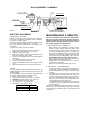
Cover,
Reigniter
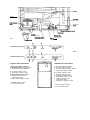
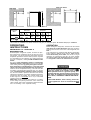
FIG. 1
\lnlett
ttttlng
\FbZkOfd
2 - WAY display panel.
FIG. 2
3 -WAY display panel.
LEGEND P-WAY AMES Model
LEGEND 3-WAY AMES Model
1. Main Power Button ON/OFF
2. AUTO/GAS Mode Selector Button
3. Temperature Selector Button
1. Main Power Button ON/OFF
2. DC Mode Selector Button
3. AUTO/GAS Mode Selector Button
4. Temperature Selector Button
B. AC Mode Indicator Lamp
C. GAS Mode Indicator Lamp
D. AUTO Mode Indicator Lamp
E. CHECK Indicator Lamp
(GAS Mode Only)
F. Temperature Indicator Lamps
G. Climate Control Switch
H. Low Ambient Switch
I-__
---A
I=L
A. DC Mode Indicator Lamp
B. AC Mode Indicator Lamp
C. GAS Mode Indicator Lamp
D. AUTO Mode Indicator Lamp
E. CHECK Indicator Lamp
(GAS Mode Only)
F. Temperature Indicator Lamps
G. Climate Control Switch
H. Low Ambient Switch
'98
ASDF
141 238393
INSTALLATION
GENERAL lNSTRUCTlON
This appliance is designed for storage of foods
and storage of frozen foods and making ice.
The refrigerators outffned herein have been design certified by A.G.A. under the ANSI 221.19 Refrigerator
Standard far installation in a mobile home or recreational
vehicle and are approved by the Canadian Gas Association.
The certifications are, however contingent on the installation being made In accordance wfth the following in-
structions as applicable.
In the U.S.A., the installation must conform with:
1. National Fuel Gas Code ANSI Z223.1 -(latest edition)
2. Manufactured Home Construction and Safety Stan-
dard, Tftfe 24 CFR, Part 3280.
3.
Recreatfonaf Vehides ANSI Al 1 9.2-(latest edition).
The unit must be electrically grounded in accordance
with the National Electric Code ANSI/NFPA 70-(latest
edition) when installed, if an external alternating current
electrical source Is utilized.
4. Any applicable focal code.
in CANADA, the lnstallation must conform with:
1. Current CAN/CGA B149 Gas installation Codes
2. Current CSA Standard 2240.4 GAS-EQUIPPED
RECREATIONAL VEHICLES AND MOBI LE HOUSING,
3. Where a flexible metal connector fs used, it must
comply w i t h the provisions of the current Standard
CAN1-6.10, METAL CONNECTORS FOR GAS
APPLIANCES.
4. Any applicable local code
The unit must be electrically grounded in accordance
with the current CANADIAN ELECTRICAL CODE C22
Parts 1 and 2.
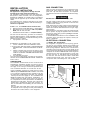
GAS CONNECTION
Hook-up to the gas supply fine is accomplished at the
manual gas valve, which is furnished with a 3/8” SAE
(UNF 5/8" -18) male flare connection. Ail completed
connections should be checked for feab with soapy
water.
IEimmB
DO NOT use a flame to check for gas leaks.
The gas suppfy system must incorporate a pressure
regulator to maintain a supply pressure of not more than
11 inches water column.
When testing the gas supply system at test pressures in
excess of 1/2 psfg, the refrigerator and fts individual
shutoff valve must be disconnected from the gas supply
piping system.
When testing the gas supply system at pressures fess
than or equal to 1/2 psfg, the appliance must be isolated
from the gas supply piping system by closing its individual
manual shutoff valve.
in case detailed instructions on the installation and
connection to the gas supply are required, contact your
deafer or distributor.
ELECTRICAL CONNECTION
120 Votts AC Connection
The refrigerator is equipped with a three-prong (grounding) plug for your protection against shock hazards and
should be plugged directly into a properly grounded
three-prong receptacle. DO NOT cut or remove the
grounding prong from this plug. The free length of the
cord is 2 feet and therefore recommended that the
receptacle be located to the left side of the refrigerator
(viewed from the rear) and approximately 6 inches from
the floor (see FIG. 3). This allows easy access through
the vent door. The cord should be routed to avoid direct
contact with the burner cover, flue cover or any other
components that could damage the cord insulation.
VENTILATION
The installation shall be made in such a manner as to
separate the combustion system from the living space
of the mobile home or recreational vehicle. Openings for
air supply or for venting of combustion products shall
have a mfnimum dimension of not fess than 1/4 inch.
Proper installation requires one lower fresh air intake
and one upper exhaust vent. The ventilation vents shown
in this instruction manual have been certified for use with
the refrigerator models listed in the table. For “Certified
Vent System Kits see page 15. The ventilation kits
must be installed and used without modification. An
opening toward the outside at floor fevef in the refrigerator compartment must be provided for ventifatfon of
heavier-than-air fuel gases. The lower vent of the recommended kits is provided with proper size openings. The
flow of combustion and ventilating air must not be obstructed.
The lower side vent is fitted wfth a panel which provides
an adequate access opening for ready serviceability of
the burner and control manifold of the refrigerator.
120 Volt AC
receptacle
FIG. 3
'98 12/06 TIS
ASDFA
MO
FAX 46 141 258393
12 Volts DC Connection
All refrigerator models require a continuous 12 volt DC
supply (even though 2-way models are designed to
operate on 120 volts AC and gas, a 12 volt DC control
is required to maintain the automatic energy system).
The DC lead connections are at terminals located at the
rear of the refrigerator. (see FIG. 1). One lead is marked
positive (+) and the other negative (-). Correct polarity
must be observed when connecting to the DC supply.
Do not use the chassis or vehicle frame as one of the
conductors. Connect two wires at the refrigerator and
route to the DC supply.
12 Volts DC Connection 3-way models
The distance the current must travel from the battery to
the refrigerator dictates the AWG wire size to be used.
Should the wire be too small for the distance, a voltage
drop will result.
The voltage drop affects the wattage output of the 12 volt
cartridge heater and resultant refrigerator performance.
Recommended wire sires are shown below.
Maximum total conductor wire length in feet and meters.
RM 3663, RM3862 RM3663, RM3863
2-way
3-way
min. wire
17 ft.
5m
27 ft.
8m
size
min. wire
size
14 AWG
10 AWG
12 AWG
8 AWG
The seating should provide a complete isolation of the
appliance’s combustion system from the vehicle interior.
NOTE: Be careful not to damage the seating strip when
the refrigerator Is put in place.
Securing the Refrigerator
After the refrigerator Is put in place, (ensuring a combustion seal at the front frame), the refrigerator is to be
secured in the enclosure with six screws. The screws
have to be installed in the following order:
STEP1:Two screws installed through the front base,
which includes the lower front strip installation.
The wires from the battery to the refrigerator must be of
large enough size to handle the toad. The connections
must be clean, tight and free from corrosion. If not, a
resulting voltage drop will cause a decreased cooling
capacity.
INSTALLING REFRIGERATOR IN
ENCLOSURE
NOTE: DO NOT install the appliance directly on
carpeting. Carpeting must be removed or
protected by a metal or wood panel beneath the appflanoe whloh extends at least
full width and depth of the appliance.
NOTE: A wood strip must be in place across the upper
opening of the enclosure. The top frame of the refrigerator will be anchored to the wood strip with screws, see
FIG. 10.
The refrigerator must be installed in a substantial enclosure and must be level. When installing the refrigerator
in the enclosure, all areas within the recess in which the
refrigerator is installed must be sealed.
Make sure that there is a complete s e a l between the
front frame of the refrigerator and the top, sides and
bottom of the enclosure. A length of sealing strip is
applied to the rear surface of the front frame for this
purpose, see FIG. 4.
The refrigerator is provided with a tower front strip (ship
ped as a loose part). The front strip is to be attached after
the refrigerator is set into the cut-out opening.
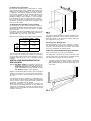
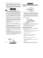
1.
Install the lower front strip by sliding it under the
bottom hinge plate, as shown in FIG. 5. The hinge
plate can be on the right or left side depending on the
door swing.
'98
SDFA
TIS
MO
46 141 238393
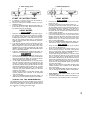
Hole for drain water ho
FIG. 8
FIG. 6
2.
3.
Once the tower front strip is slipped under the hlnge,
the part is possible to swing into place as shown in
FIG. 6.
Secure the refrigerator and the lower front strip with
two screws:
One screw through the hinge, snd on the opposite
side one screw through the lower front strip. (FIG. 6).
STEP 2: Two screws Installed In the top frame.
The top decoration panel must be removed from the
refrigerator before the screws can be installed.
Open the upper door and gently push the tabs out of the
hole in the hinge with a flat blade screwdriver, (both
sides). See FIG. 7.
Carefully tilt the top decoration panel and lift up to
remove from top frame. Be careful not to damage the
circuit board and wires.
FIG. 7
1
tnstatt the two screws in the top frame, the holes are
accessible from underneath.
Seal the opening for the screws with aluminum tape.
Replace the top decoration panel. Be careful not to pinch
the wires behind the panel. Make sure the tabs snap
back into the holes in the hinge plate.
STEP 3: T w o screws Installed in the rear base.
See FIG. 8.
Failure to follow the sequence In securing refrigerator in
enclosure can cause leakage between the frame and
cabinet.
Any space between the counter, storage area or ceiling
and top of the refrigerator greater than 1-1/2 inches
should be blocked. The heal produced at the rear of the
refrigerator will become trapped in thts space, making
the top of the refrigerator hot and reduce the efficiency
of the refrigerator.
Drain water hose
A hole must be drilled through flooring see FIG. 8.
The hole must be drilled in the cut out opening of the
base plate at the rear of the refrigerator. The installer
MUST maks sure that the hose does not kink when run
through the floor. Seal around the hose that goes
through the drilled hole. If a longer hose than supplied Is
required to get the water to drain outside of the vehicle,
the installer will have to supply the extra length of hose.
TESTING LP GAS SAFETY
SHUTOFF
The gas safety shut-off must be tested after the
refrigerator is connected to the LP gas supply.
To test the gas safety shut-off, proceed as follows:
1. Start the refrigerator and switch to the GAS mode.
(see start up instructions).
2. Check that the gas flame Is lit and the GAS mode
Indicator lamp (C) is on.
3. Close the manual gas shut-off valve at the back of
the refrigerator. (See FIG. 1).
4. Wait for one minute. The CHECK indicator lamp (E)
should be on and the GAS mode indicator lamp (C)
should be off.
5. Remove protection cover (see FIG. 1) and open the
manual gas shut-off valve. Do not change any button
positions on the control panel. Apply a non-corrosive
commercial bubble solution to the burner jet orifice.
6. No bubbles should appear at the opening of the
burner jet orifice. The presence of bubbles indicates
a defective gas safety shut-off and service is required.
7. If no bubbles were present at the burner jet orifice, it
should be rinsed with fresh water. Be careful not to
damage the burner jet orifice. Replace cover and
press the main power ON/OFF button (1) OFF and
back ON. Normal operation of the burner should
return. Allow the burner to operate for a minimum of
five minutes.
'96
FSDF
TIS
46 141 238393
HO
CERTIFIED INSTALLATION
Certified installations require one roof vent and one
lower side vent.
For "Certified Vent System Kits” see page 15.
For further information contact your dealer or distributor.
NOTE: The upper vent should be
centered over the condenser coil
at the beck of the refrigerator.
I
I
I
NOTE: Wood Strip
MUST be in place.
Minimum 1
ventilation ,
CLEARANCE%
FIG. 9
METHODS OF INSTALLATION
The method of installation is shown in FlG. 9. It is
essential that all maximum or minimum dimensions are
strictly maintained as the performance of the refrigerator
is dependent on adequate flow of air over the rear of the
refrigerator,
VENTILATION HEIGHTS
r Installation with roof
vent and tower side vent
Minimum ventilation
heights in
Refrigerator
Inches
mm
57-3/4
1 63-3/4
1465
1620
RM3662, RM 3663
RM 3662; RM 3963
Minimum clearances In inches to combustible materials
are:
G: Top
0
K: Slde 0
L: Bottom 0
M: Rear 0
N:
See NOTE: Clearance "N” below.
NOTE: Clearance “M” is between the rearmost part of
the refrigerator and the wall behind the refrigerator.
NOTE: Clearance “N" is the distance between the bottom of the lower vent to the roof material. For ventilation
height, see table VENTILATION HEIGHTS
See Figures 9, and 10.
ASDFA
'98
TIS
PO
46 141 238393
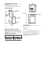
View from above
FIG. 11
RM 3662 inch
Recess
Dimensions
Overall
Dimensions
Refrigerator
Model
H e i g h t Width
A
B
54-21/32 I 24-7/8
Depth
c
26-1/32
Height Width
W
H
53-3/4 23-11/16
Depth
D
2 4
1366
60-51/64
681
26-1/32
1365
602
59-15/16 23-11/16
810
24
R M a663
RM
d 3662 ::
RM
M 3663
mm
1544
632
1 24-7/8
632
661
1622
602
610
This method of installation and these clearances will give you adequate space for service and proper installation.
OPERATING
INSTRUCTIONS
IMPORTANCE OF LEVELING A
REFRIGERATOR
In an absorption refrigerator system, ammonia is liquefied in the finned condenser coil at the top rear of the
refrigerator. The liquid ammonia then flows into the
evaporator (inside the freezer section) and is exposed
to a circulating flow of hydrogen gas, which causes the
ammonia to evaporate, creating a cold condition in the
OPERATION
Before starting the refrigerator, check that all the manual
gas valves are in the ON position. DO NOT forget the
manual shut-off valve on the rear of the refrigerator, see
FIG. 1.
This refrigerator Is equipped with a semi Automatic
Energy Selector (AMES) control system, which can be
set to automatically select either 120 volt AC or LP gas
operation, or if desired LP gas only. On 3-way models
the control system can manually be set to DC operation,
The refrigerator controls will work down to 9.6 voltDC.
freezer.
The tubing in the evaporator section is specifically
sloped to provide a continuous movement of liquid ammonia, flowing downward by gravity through this section.
If the refrigerator is operated when it is not level and the
vehicle is not moving, liquid ammonia will accumulate in
sections of the evaporator tubing. This will stow the
circulation of hydrogen and ammonia gas, or in severe
cases, completely block it resulting in a loss of cooling.
Any time the vehicle is parked for several hours with the
refrigerator operating, the vehicle should be leveled to
prevent this loss of cooling. The vehicle needs to be
leveled only so It Is comfortable to live in (no noticeable
‘sloping of floor or walls).
When the vehicle is moving, the leveling is not critical,
as the rolling and pitching movement of the vehicle will
pass to either side of level, keeping the liquid ammonia
from accumulating In the evaporator tubing.
Most LP gas appliances used-in recreational vehicles are vented to the outside of the vehicle,
When parked close to a gasoline pump, it Is
possible that the gasoline fumes could enter
this type of appliance and ignite from the
burner flame, CAUSING A FIRE OR AN EXPLOSION.
FOR YOUR SAFETY, when refueling, shut of all
LP gas appliances which are vented to the outside.
'98
ASDFA
lwi 46 141 238393
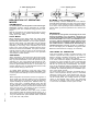
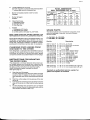
2 - WAY display panel.
3 -WAY display panel.
A
B
C
D
E
F
3-WAY MODEL
START UP INSTRUCTIONS
A continuous 12 volt DC supply must be available for
the electronic control to function.
B. Press the main power ON/OFF button (1) to the
DOWN position.
C. Press the TEMPERATURE SELECTOR button (3)
P-WAY Model or (4) 3-WAY Model until the lamp at
the desired setting is Illuminated.
AUTO MODE
A.
1.
2.
2-WAY MODEL
AUTO MODE
Press the AUTO/GAS mode selector button (2) to
turn ON the Auto lamp (D). If 120 volts AC is available, the AC mode indor lamp (B) will illuminate
indicating AC operation. If 120 volts AC is not availabie, the GAS mode indicator tamp (C) will illuminate
and the control system will automatically switch to
GAS operation.
2. If the CHECK indicator lamp (E) illuminates and the
GAS mode indicator lamp (C) is off, the controls have
failed to ignite the burner in the GAS mode. GAS
operation may be reset by pressing the main power
ON/OFF button(l) to the OFF then ON position. (See
step 2 under GAS MODE).
3. Press the TEMPERATURE SELECTOR button (3)
until the lamp at the desired position is iiiuminated.
FAS MO=
1. Press the AUTO/GAS mode selector button (2) to
turn OFF the Auto lamp (D). The GAS mode indicator
lamp (C)will illuminate. Within 45 seconds the burner
should be ignited and operating normaiiy.
2. On the initial refrigerator start-up, it may take longer
than 46 seconds to allow air to be purged from the
gas tine. if the gas does not ignite within 45 seconds
the CHECK indicator lamp (E) will illuminate and the
GAS mode indicator lamp (C) will go off. To reset
when the CHECK indicator lamp (E) is iiiuminated,
press the main power ON/OFF button (1) to the OFF
and then ON position.
NOTE: Do not continue to reset GAS operation if the
CHECK indicator lamp continues to be illuminated
after several tries.
3. Press the TEMPERATURE SELECTOR button (3)
until the lamp at the desired position is iiiurnlnated.
1.
TO SHUT OFF THE REFRIGERATOR
The refrigerator may be shut off while in any mode of
operation by pressing the main power ON/OFF button
to the UP (OFF) position. This shuts off ail DC power to
the refrigerator. inciudinc the interior iiaht.
3.
4.
Press the DC mode selector button (2) to turn OFF
the DC lamp (A).
Press the AUTO/GAS mode selector button (3)
(ii required) to turn ON the Auto lamp (D). If 120 volts
AC is available, the AC mode Indicator lamp (B) will
illuminate indicating AC operation. If 120 volts AC is
not avaiiabie, the GAS mode indicator lamp (C) will
illuminate and the control system will automatically
switch to GAS operation.
if the CHECK indicator lamp (E) illuminates and the
GAS mode indicator lamp (C) is off, the controls have
failed to ignite the burner in the GAS mode. GAS
operation may be reset by pressing the main power
ON/OFF button (1) to the OFF then ON position. (See
step 2 under GAS MODE).
Press the TEMPERATURE SELECTOR button (4)
until the lamp at the desired position is iiiuminated.
GAS MODE
1.
Press the DC mode selector button (2) (if required)
to turn OFF the DC lamp (A).
2. Press the AUTO/GAS mode selector button (3) to
turn OFF the Auto lamp (D). The GAS mode indicator
lamp (C) will illuminate. Within 45 seconds the burner
should be ignited and operating normally.
3. On the initial refrigerator start-up, it may take longer
then 45 seconds to allow air to be purged from the
gas line. if the gas does not ignite within 45 seconds
the CHECK indicator lamp (E) will illuminate and the
GAS mode indicator lamp (C) will go off. To reset
when the CHECK indicator lamp (E) is illuminated,
press the main power ON/OFF button (1) to the OFF
and then ON position,
NOTE: Do not continue to reset GAS operation If the
CHECK indicator lamp continues to be illuminated
after several tries.
4. Press the TEMPERATURE SELECTOR button (4)
until the lamp at the desired position is illuminated.
1.
2.
DC MODE
Press the OC mode indicator button (2) to turn ON
the DC lamp (A).
Press the TEMPERATURE SELECTOR button (4)
until the lamp at the desired position is illuminated.
'96
SDF
TIS
46 141 236393
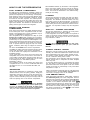
3 -WAY display panel.
2 - WAY display panel.
D
B
E
c
DESCRIPTION OF OPERATING
MODES
THERMOSTAT
The thermostat on the refrigerator controls both the gas
and electric operation, thereby eliminating the necessity
of resetting each time a different energy source is employed.
After the initial start-up, the thermostat should be moved
from ‘COLDEST’ to the desired temperature setting,
usually about mid setting.
AUTO MODE
When operating in the AUTO mode, the AUTO mode
indicator lamp (D) will illuminate. The control system will
automatically select between AC and GAS operation
wlth AC having priority over GAS. Either the AC indicator
lamp (B) or the GAS indicator lamp (C) will illuminate
depending on the energy source selected by the control
system. If the control system is operating with AC energy
and it then becomes unavailable , the system will automatically switch to GAS. As soon as AC becomes available again the control will switch back to AC regardless
of the status of GAS operation.
GAS MODE
When operating in the GAS mode the AUTO mode
indicator lamp (D) will be off and the GAS mode indicator
lamp (C) will be illuminated. This mode provides LP gas
operation only. The control system will activate the ignition system and will attempt to light the burner for a
period of approximately 45 seconds. If unsuccessful, the
CHECK indicator lamp (E) will illuminate and the GAS
mode indicator lamp (C) will turn off.
To restart GAS operation, press the main power
ON/OFF button (1) to the OFF and then ON position. The
control system will attempt a new 45 second ignition
sequence.
If the refrigerator has not been used for a tong time or
the LP tanks have just been refilled, air may. be trapped
in the supply lines. To purge the air from the lines may
require resetting the main power ON/OFF button (1)
three or four times. If repeated attempts fail to start the
LP gas operation, check to make sure that the LP gas
supply tanks are not empty and all manual shutoff valves
in the lines are open. If the problem is still not corrected,
contact a service center for assistance.
If the control is switched to AC or DC (3-way models
only) operation while the CHECK indicator lamp is on, it
will function properly, but the CHECK lndicator lamp will
not go off until the main power ON/OFF button is pressed
to the OFF then ON position.
A
D
E
B C
F
DC.MODE (3-way models only)
When operating In the DC mode the DC mode indicator
tamp (A) will be illuminated. All other mode lamps will be
off. The DC mode overrides all other operating modes.
If one of the other operating modes is desired, the DC
selector button (2) must be pressed to turn OFF the DC
lamp (A).
IMPORTANT:
To prevent the refrigerator from being left on and
draining the battery when the vehicle’s engine Is not
running and charging the battery. It It recommended
that an automatk cut-out relay be Installed between
the battery and the refrigerator toggle switch so that
the refrigerator will not draw current when the lgnition of the vehicle is switched off. Alternatively, a
suitable plug and receptacle should be installed In
the 12 Volt supply line, so that the refrigerator can
be disconnected from the supply, as necessary.
LIMP MODE OF OPERATION
This control system contains a feature where It will
continue to operate the cooling system in the event of a
failure of a major operating component. Two different
modes of operation can occur in this category.
If for some reason the display module becomes non
functional, the control system will revert to full automatic
operation selecting the best energy source available
with AC, DC (3-way only) and GAS priority. The temperature of the refrigerator will be maintained at the MID
position within normal temperature tolerances. The power module will continually attempt to reestablish operation of the display module.
The second limp mode of operation will execute when a
failure of the temperature sensing device or associated
electronic circuitry occurs. If thls should occur, the control system will operate on the energy source selected
via the control panel. The cooling unit will run continuously on the selected energy source. The refrigerator
will continue to operate in this mode Indefinitely or until
a new sensor is installed and the system is reset.
'98
ASDF
TIS
FAX 46 141 238393
HOW TO USE THE REFRIGERATOR
FOOD STORAGE COMPARTMENT
The food storage compartment is completely closed and
unventilated, which is necessary to maintain the required low temperature for food storage. Consequently,
foods having a strong odor or those that absorb odors
easily should be covered. Vegetables, salads etc. should
be covered to retain their crispness. The coldest positions
in the refrigerator are under the coaling fins and at the
bottom of ths refrigerator. The Warmer areas are on the
upper door shelves. This should be considered when
placing different types of food in the refrigerator.
FROZEN FOOD STORAGE
COMPARTMENT
Quick frozen soft fruits and ice cream should be placed
in the coldest part of the compartment which is at the
bottom of the aluminum liner. Frozen vegetables, may be
stored In any part of the compartment.
This compartment is not designed for deep or quick
freezing of food. Meat or Rsh, whether raw or prepared,
can be stored in the frozen food storage compartment
provided they are pm-cooled Rrst in the refrigerator. They
can be stored about three times longer in the frozen food
compartment as compared to the fresh food compartment. To prevent food from drying out, keep it in covered
dishes, containers, plastic bags or wrapped in aiuminum
foil.
Ice cubes can be made in the freezer compartment.
For faster ice making, the trays should be placed in direct
contact with the bottom of the freezer compartment.
Ice will be made more rapidly if the thermostat is set at
ifs Mghest position.
It is a good idea to do this a few hours before the
anticipated need for ice, but be sure to move back to
normal setting, usually about mid setting when the ice is
formed. Food in the lower compartment may be frozen
if the setting is left on “COLDEST’position.
Refrigerator volume
The combined volume of the freezer and fresh food
compartments are 6 cu. ft. for the models RM 3662 and
RM 3663 and 6 cu. ft. for the models RM 3662, and
RM 3863.
DEFROSTING
Shut off the refrigerator by pressing the main power
ON/OFF button to the UP (OFF) position. Empty the
refrigerator, leaving the drip tray under the finned evaporator, and the cabinet and freezer doors open. Defrosting time can be reduced by filling the ice trays with hot
water and placing them in the freezer compartment.
ms!sm
DO NOT use a hot alr Mower. Permanent damage
could result from warping the metal or plastic parts;
DO NOT use a knife or an Ice pick, or other sharp
tools to remove frost from the freezer compartment
They can create a leak in the ammonia system.
When all frost is melted, dry the interior of the refrigerator
with a clean cloth. Replace all food and set the thermostat to the COLDEST temperature setting for a few
hours. Then reset the thermostat to the desired sefflng,
usually at mid setting.
CLEANlNG
Cleaning the refrigerator is usually done after it is defrosted or put into storage. To dean the interior liner of the
refrigerator, use lukewarm weak soda solution. Use only
warm water to clean the Rnned evaporator, ice trays and
shelves. NEVER use strong chemicals or abrasives to
clean these parts as the protective surfaces will be
damaged. It Is important to always keep the refrigerator
clean.
SHUT OFF - STORAGE PROCEDURE
Shut off the refrigerator by pressing the main power
ON/OFF button to the UP (OFF) position,
If the refrigerator will not be in operation for a period of
weeks, it should be emptied, defrosted, cleaned and the
doors left ajar. The ice trays should also be dried and
kept outside the cabinet.
DO NOT store explosive substances in the refrigerator, such as cigarette lighter gas, petrol, ether or
the Iike.
CLIMATE CONTROL HEATER
During the summer months of high temperatures and
humidity, the metal frame between the freezer and fresh
food compartments may have water droplets forming.
The number of water droplets will increase if the vehicle
isn’t air conditioned during these months.
This refrigerator comes standard with a 12 volt (DC)
climate control that will evaporate the water droplets
when they form.
To have the climate control on, you position the switch
("G” see figure 2) located beneath the top decoration
panel that houses the control panel to ON. The climate
control can be left on continuously or only used when
temperatures require it.
NOTE: The climate control will draw 12 volts DC power
continuously when in the ON position. It should ba turned
OFF when a charging source is not available.
LOW AMBIENT SWITCH
All RV absorption refrigerators, while similar, operate a
little differently than your home refrigerator. Dometic
designers and engineers have equipped your refrigerator with an exclusive feature that allows for trouble-free
operation In low ambient temperature (like below 5OT)
for extended periods of time. Simply turn on the low
ambient switch located beneath the top decoration panel
that houses the control panel (see figure 2, “H"). Once
the outdoor temperature is above 5O”F, the low ambient
switch should be turned off.
'98 12/08 TIS
ASDF
PVU
FAX 46 141 238393
GAS EQUIPMENT ASSEMBLY
SOLENOID
--&ff%
PRESSURE TEST PORT
FIG.12
T - T
CARTRIDGE HEATER
The heat necessary for the operation of an absorption
cooling unit is supplied by an electric heater mounted In
a pocket of the boiler system.
The 3-WAY Model Is equipped with two electrical heaters, one for 120 volt AC and one for 12 volt DC.
The P-WAY Model is equipped with one electric heater
120 volt AC.
To replace the heater proceed as follows;
5.
6.
7.
8.
9.
THERMOCOUPLE
!-I
ELECTRIC EQUIPMENT
1.
2.
3.
4.
r/
NUT
VALVE
Disconnect the wall plug, and the 12 volt wires.
Remove the power module cover see FIG. 1
Disconnect the heater leads.
With a pair of pliers unfold the lug holding the lid of
the boiler casing and open the lid.
Remove some insulation wool so that the heater is
aocessible.
Turn and lift the heater out of its pocket.
Fit the new heater into the pocket.
Connect the leads and put on the power module
cover.
Reset the lnsulation and close the lid of the boiler.
MAINTENANCE & SERVICE
The user should bs aware of service that must be
done on a regular schedule to keep the refrigerator
operating properly. The service should only be
performed by a qualified technician who is familiar
with LP gas systems and refrigerators.
1. REFRIGERATOR REMOVAL
Before working on the refrigerator, make sure the AC
voltage and DC voltage leads are diited. Shut
off the gas supply. Disconnect the gas supply lii at
the rear of the refrigerator, see FIG. 1. Always use a
back up wrench when loosening and tightening this
connection. Cap the gas supply line, loosen the
screws anchoring the refrigerator to the enclosure
and slide the refrigerator out of the compartment.
When replacing the refrigerator make sure that the
sealing strips are property positioned.
Replacement is the reverse of removal. Check all
connections for gas leaks.
Refer to section INSTALLATION, page 4 to 6.
2. PERIODIC MAINTENANCE
FUSES
The 2-way AMES models are equipped with 2 fuses, one
for the refrigerator control system and one for the AC
cartridge heater.
The 3-way AMES models are equipped with a third fuse
for the DC cartridge heater. (see table below)
To replace fuse(s) proceed as foilows.
1. Disconnect the wall plug, and the 12 volt wires.
2. Remove the power module cover. See FIG. 1.
3. Snap the fuse out of the fuse holder.
4. Fit a new fuse in to the fuse holder.
5. Replace the power module cover.
3
’ Control system
3 Amp
AC heater
5 Amp
DC heater
35 Amp
To keep your Dometic refrigerator operating efficiently and safely, periodic inspectlon and cleaning of
several components once or twice a year is recommended.
A. It is important to keep the area at the back of the
refrigerator clean. Check the lower vent, upper vent
and area between these openings for any obstructions such as bird/insect nests, spider webs, etc.
Clean the coils on the back of the refrigerator. Use a
soft bristled brush to dust off the coils.
It is Important to keep the refrigerator area free from
combustible material, gasoline and other flammable
vapors or liquids.
NOTE: The following maintenance is required once or
twice a year, but should only be done by a qualified
serviceman who is familiar with LP gas systems and
refrigerators.
ASFSA
'98
TIS
46 141 238393
B . Check all connections in the LP gas system (at the
back of the refrigerator) for gas leaks. The LP gas
supply must be turned on. Apply a non-corrosive
bubble solution to all LP gas connections. The appearance of bubbles indicates a leak end should be
repaired immediately by a QUALIFIED SERVICEMAN WHO IS FAMILIAR WITH GAS SYSTEM AND
REFRIGERATORS.
DO NOT use a wire or pin when cleaning the burner
jet as damage can occur to the precision opening.
This can cause damage to the refrigerator or create
a fire hazard.
DO NOT use a flame to check for gas leaks.
Check the AMES control system by connecting/disconnecting 120 volt AC power, start/stop the engine,
etc. Compare the operation with the operation described in description of operating modes. Page 10.
D. The LP gas pressure should be checked and the
main regulator m-adjusted if pressure is incorrect.
The correct operating pressure is 11 inches of water
column. The correct place to take the LP gas pressure is at the test port just ahead of the burner jet.
(See FIG. 12).
E. Inspect the flue baffle. It should be reasonably clean
and free of soot. Heavy soot formation indicates
Improper functioning of the burner. The flue and
burner both require cleaning in the following manner.
1. Unplug the refrigerator power cord from the 120 volt
AC outlet. (See FIG. 3).
2. Disconnect or shut off the 12 volt power to the
refrigerator.
3. Turn manual shutoff valve to OFF. (See FIG. 1).
4. Remove cover from the bumer housing. (See FIG.
1).
5. Disconnect the wire from the high voltage electrode.
6. Remove the burner mounting screw end remove the
burner assembly. (See FIG. 12).
7. Remove the wire and flue baffle from the top of flue
tube. Clean the flue from the top using a flue brush.
Blowing compressed air into the flue will not properly
clean soot and scale out of the flue tube. Replace the
flue baffle.
8. Clean burner tube with a brush. Blow out burner with
compressed air.
9. Before removing burner jet, clean burner area of soot
and scale that fell out of flue tube. Remove the bumer
jet. Soak the- jet in wood alcohol and Mow it out with
compressed air. Re-install and tighten burner jet
NOTE: The color of the flame shall be clear blue over
the slots of the burner. (See FIG. 13).
C.
10. Reinstall burner, being careful that the end of the
burner fits into the slot on the burner bracket. Check
to make sure slots are centered under the flue tube
and the thermocouple is positioned properly (tip of
thermocouple extends over two slots of burner).
11. Se sure to reconnect the wire to high voltage electrode. Check the electrode for proper location and
gap. (See FIG. 14).
FIG. 14
Electrode
to 3/16”
mm)
Burner
12. Turn on manual gas shutoff valve and check all
fittings for leaks.
13. Connect 120 volt power cord to the outlet and reconnect or turn on the 12 volt DC power.
14. Check LP gas safety shutoff. See pege 8.
TROUBLESHOOTING
The Refrigerator Does Not Cool Properly
A.
Burner jet clogged.
Clean. (See section Maintenance & Service, Item 2.
Periodic Maintenance, Paragraph E. Item l-14.
B.
Check level of refrigerator.
C. Venting problem.
Restriction in air flow across cooling unit
D. Heavy frost buildup on evaporator fins.
Defrost.
Clear blue color
FIG. 13
E.
Flue baffle not inserted properly in flue tube.
F.
Improperly set thermostat.
See section Operating Instructions, part Start Up
Instructions.
G. Burner dirty.
Clean. See section Maintenance & Service, Item 2.
Periodic Maintenance, Paragraph E. Item l-14.
ASFSA
'98
ASFD
46 141 238393
AD
4
-1
CERTIFIED VENT SYSTEM
Refr.
Model
Kit
No.
Components
RM 3662
RM3663
4A
Roof Vent
KITS
RM3662
RM 3663
Lower Side Vent
For further information, contact your deafer or distributor.
Drawing
3103633 Base
3103634 cap
(Both Required)
3102364
3102277
3102070
3102972
3101534
3101782
3101337
'98
ASFD
TIS
FAX 46 141 238393
MO
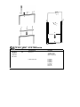
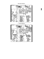
RM 3662, RM 3862
BURNER HOUSING
CHASSlS GROUND
CIRCUIT BOARD DISPLAY
CIRCUIT BOARD POWER
@- TERMINAL B L O C K
@TEST POINT
@- THERMISTOR
~TIIERWWUPLE
@-s!fltw L.A.T
HEATER 120 V AC
HEATING CABLE
PROTECT I VE EARTH
RM
3863, RM 3863
BURNER HOUSING
@-swITctl LIGHT
CHASSIS GROUND
@ToIbwutL BLOCK
C I R C U I T BOARD DISPLAY @-1EST POINT
CIRCUIT BOARD POWER
@- THERM I STOR
@-THERuoaUPLE
@-t11TM L.A.T
HEATER 12V DC
HEATER 120V A C
HEATING CABLE
PROTECTIVE EARTH