1
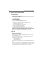
DSM300 & DSM30
Digital Sounder
Module
Installation Manual
Document number: 87080-1
Date: November 2006
Trademarks and registered trademarks
HSB, Raymarine and SeaTalk are registered trademarks of Raymarine plc.
All other product names are trademarks or registered trademarks of their
respective owners.
Contents of this handbook ©Raymarine 2006
3
Contents
Trademarks and registered trademarks ............................................ 2
Important Information .........................................................................................5
Intended Use .......................................................................................... 5
Safety Notices ...................................................................................... 5
EMC Conformance ................................................................................. 6
Declaration of Conformity ................................................................ 6
Product Disposal .................................................................................... 6
Waste Electrical and Electronic Equipment (WEEE) Directive ........... 6
Warranty .............................................................................................. 6
Chapter 1: DSM Installation ..............................................................................7
1.1 Introduction ........................................................................................... 7
Planning the Installation ........................................................................ 7
EMC Installation Guidelines ................................................................. 7
Suppression Ferrites ......................................................................... 8
Connections to Other Equipment ..................................................... 8
1.2 Unpacking and Inspecting the Components ........................................... 9
Cable Options ...................................................................................... 10
1.3 Selecting Sounder Module Mounting Location .................................... 10
1.4 Mounting the Sounder Module ........................................................ 11
1.5 Cable Runs ......................................................................................... 14
1.6 System Connections ........................................................................... 14
Transducer Connection ...................................................................... 15
DC Power Connection ........................................................................ 15
Ground Connection ............................................................................ 18
1.7 Display Configuration ...................................................................... 18
Configuring E Series Displays ............................................................. 18
Configuring C Series Displays ............................................................. 19
Configuring hsb2 PLUS (Pathfinder) Series Displays ........................... 20
Chapter 2: Maintenance and Problem Solving ...............................................21
2.1 Maintenance ........................................................................................ 21
Routine Checks .................................................................................... 21
Cleaning Instructions ........................................................................... 21
EMC Servicing and Safety Guidelines ................................................... 22
2.2 Resetting the System ............................................................................ 23
For E Series and C Series Displays... ................................................ 23
For hsb2 PLUS Series Displays... ..................................................... 23
2.3 Problem Solving ................................................................................... 25
Common Problems and Their Solutions ................................................ 25
Status LED .......................................................................................... 26
4
DSM300 and DSM30 Installation Manual
2.4 How to Contact Raymarine ...................................................................28
On the Internet .....................................................................................28
Customer Support ..........................................................................28
In the US ...............................................................................................28
Accessories and Parts .....................................................................28
Technical Support ...........................................................................29
Product Repair and Service .............................................................29
In Europe ..............................................................................................30
Technical Support ...........................................................................30
Accessories and Parts .....................................................................30
Worldwide Support ..............................................................................30
Appendix:
Specifications...............................................................................31
General .................................................................................................31
Sounder Features ..................................................................................31
Index ......................................................................................... 33
5
Important Information
Raymarine DSM300 and DSM30 Digital Sounder Modules provide echo sounder
data that can be displayed on Raymarine E Series, C Series, and hsb2 PLUS
(Pathfinder) Series display units.
This manual contains important information for installing and maintaining your
Digital Sounder Module. Raymarine’s Technical Services representatives or your
local dealer will be available to answer any questions you may have.
Instructions on how to operate the fishfinder application can be found in the
handbook for your particular display system.
Intended Use
DSM300 and DSM30 Digital Sounder Modules are intended for depth finding and
fishfinding purposes on recreational (non-IMO/SOLAS class) boats. Echo
sounders require an appropriate Raymarine transducer and interconnecting
cable.
Safety Notices
This equipment must be installed and operated in accordance with the
instructions contained in this manual. Failure to do so can result in personal injury
and/or navigational inaccuracies. In particular:
CAUTION: High Voltage
Digital Sounder Modules contains high voltages. Adjustments require specialized
service procedures and tools only available to qualified service technicians – there
are no user serviceable parts or adjustments. The operator should never remove
the cover or attempt to service the equipment.
CAUTION: Transducer Cable
Removing the transducer cable from the rear of the DSM300 or DSM30 while the
sounder module is powered on can cause sparks. Only remove the transducer
cable after power has been removed from the DSM. As with any electronic device,
be sure the sounder module is mounted where it is well ventilated and free from
gasoline fumes.
If the transducer cable is accidentally removed while the DSM is powered on,
remove power from the sounder module, replace the transducer cable, and then
return power to the module. As a safety feature, the sounder module only
recognizes that the transducer is connected at power-up.
6
DSM300 and DSM30 Installation Manual
EMC Conformance
All Raymarine equipment and accessories are designed to the best industry
standards for use in the recreational marine environment.
The design and manufacture of Raymarine equipment and accessories conform to
the appropriate Electromagnetic Compatibility (EMC) standards, but correct
installation is required to ensure that performance is not compromised.
Declaration of Conformity
Raymarine plc declare that the DSM300 and DSM30 Digital Sounder Modules are
in compliance with the essential requirements of EMC directive 2004/108/EC.
The original Declaration of Conformity certificate may be viewed on the relevant
product page at www.raymarine.com.
Product Disposal
Waste Electrical and Electronic Equipment (WEEE) Directive
The WEEE Directive requires the recycling of waste electrical and electronic
equipment. While the WEEE Directive does not apply to some of Raymarine’s
products, we support its requirements as part of our environmental policy and we
ask you to be aware of how you should dispose of this product.
The wheelie bin symbol found on our products signifies that it should not be
disposed of in general waste or landfill. Please contact your local dealer, national
distributor or Raymarine Technical Services for information on product disposal.
Warranty
To register your Digital Sounder Module ownership, please take a few minutes to
fill out the warranty registration card found at the end of this handbook. It is very
important that you complete the owner information and return the card to the
factory in order to receive full warranty benefits.
7
Chapter 1: DSM Installation
1.1 Introduction
This chapter provides details for mounting the DSM300 and DSM30 and
connecting to the display.
For the system to display depth, water temperature and speed, you must install
the transducer type(s) capable of transmitting the appropriate data.
Planning the Installation
Before you install your system, plan the installation, considering:
• Location of the sounder module, as described in Section 1.3
• Cable Runs, as described in Section 1.5
• Correct transducer for your application
EMC Installation Guidelines
All Raymarine equipment and accessories are designed to the best industry
standards for use in the recreational marine environment.
Their design and manufacture conforms to the appropriate Electromagnetic
Compatibility (EMC) standards, but correct installation is required to ensure that
performance is not compromised. Although every effort has been taken to ensure
that they will perform under all conditions, it is important to understand what
factors could affect the operation of the product.
The guidelines given here describe the conditions for optimum EMC performance,
but it is recognized that it may not be possible to meet all of these conditions in all
situations. To ensure the best possible conditions for EMC performance within the
constraints imposed by any location, always ensure the maximum separation
possible between different items of electrical equipment.
For optimum EMC performance, it is recommended that wherever possible:
• Raymarine equipment and cables connected to it are:
• At least 5 ft (1.5 m) from any equipment transmitting or cables carrying
radio signals, e.g., VHF radios, cables and antennas. In the case of SSB
radios, the distance should be increased to 7 ft (2 m).
• More than 7 ft (2 m) from the path of a radar beam. A radar beam can normally be assumed to spread 20 degrees above and below the radiating
element.
8
DSM300 and DSM30 Installation Manual
• The equipment is supplied from a separate battery from that used for engine
start. Voltage drops below 10 V and starter motor transients can cause the
equipment to reset.
This will not damage the equipment, but may cause the loss of some information and may change the operating mode.
• Raymarine specified cables are used. Cutting and rejoining these cables can
compromise EMC performance and must be avoided unless doing so is
detailed in the installation manual.
• If a suppression ferrite is attached to a cable, this ferrite should not be
removed. If the ferrite needs to be removed during installation it must be reassembled in the same position.
Suppression Ferrites
The following illustration shows typical cable suppression ferrites used with
Raymarine equipment. Always use the ferrites supplied by Raymarine.
D3548-3
Connections to Other Equipment
If your Raymarine equipment is to be connected to other equipment using a cable
not supplied by Raymarine, a suppression ferrite must always be attached to the
cable that is closest to the Raymarine unit.
Chapter 1: DSM Installation
9
1.2 Unpacking and Inspecting the Components
Unpack your system carefully, to prevent damage to the equipment. Save the
carton and packing, in case you need to return the unit for service. Check that you
have all the correct system components:
DSM300
Power Cable, 3m
part no. R69053
DSM300
& DSM30
Installation
Manual
Installation Manual,
part no. 87080
DSM300
Operation
Manual
Operation Manual for PLUS
Displays, part no. 81249
C Series Network Cable, 3m
part no. E65010
hsb2 adapter, 4-pin to 3-pin
part no. R69081
Mounting Screws,
No.8 (x4)
D9598-1
DSM300 Digital Sounder Module,
part no. E63069
DSM30
Power Cable, 3m
part no. R69053
Mounting Screws, No.8 (x4)
C Series Network Cable, 3m
part no. E65010
DSM300
& DSM30
Installation
Manual
Installation Manual,
part no. 87080
D9599-1
DSM30 Digital Sounder Module,
part no. E63074
10
DSM300 and DSM30 Installation Manual
A 3m-long cable is included for connecting your sounder module to a C Series or
hsb2 PLUS (Pathfinder) Series display. Longer cables and connection cables for
other types of systems must be purchased separately.
Note: C Series displays have 4-pin connectors while the older hsb2 PLUS Series displays
have a 3-pin configuration. This requires that you use a 4-pin to 3-pin adapter (Raymarine
part number R69081) when connecting a sounder module to an hsb2 PLUS Series display.
This adapter is included with the DSM300 but must be ordered separately with a DSM30.
Select from the following cable options:
Cable Options
System
Cable
Part No.
E Series
SeaTalkhs Network Cable, RJ-45, 1.5m
SeaTalkhs Network Cable, RJ-45, 5m
SeaTalkhs Network Cable, RJ-45, 10m
SeaTalkhs Network Cable, RJ-45, 20m
E55049
E55050
E55051
E55052
C Series
C Series Network Cable, 4-pin-to-4-pin, 10m
E65011
hsb2 PLUS Series
(Pathfinder)
hsb2 In Line Terminator
hsb2 Splitter Cable
hsb2 Adapter Cable, 4-pin to 3-pin
R58117
E55040
R69081
1.3 Selecting Sounder Module Mounting Location
DSM300 and DSM30 sounder modules are waterproof to IPX-7 is and is designed
to be mounted either above or below deck.
Mount the DSM where it is:
•
•
•
•
protected from physical damage and excessive vibration
protected from prolonged exposure to rain, salt spray and direct sunlight
well ventilated
as close to the transducer as possible
Do not locate the DSM:
• in the engine compartment
• on the main console
When planning the installation, the following should be considered to ensure
reliable and trouble free operation:
• Access: There must be sufficient space below the unit to enable cable connections to the panel connectors, avoiding tight bends in the cable.
Chapter 1: DSM Installation
11
• Interference: The selected location should be far enough away from
devices that may cause interference, such as motors, generators, and radio
transmitter/receivers. (See the EMC guidelines earlier in this chapter.)
• Magnetic compass: Mount the unit at least 3 ft (1 m) away from a magnetic
compass.
• Cable runs: The unit must be located near a DC power source. The power
cable supplied is 10 ft (3 m).
• Environment: Provide good ventilation to prevent overheating.
CAUTION: Do Not Remove the Transducer Cable
Removing the transducer cable from the sounder module while
power is turned on can cause sparks. As with any electronic
device, be sure the sounder module is mounted where it is well
ventilated and free from gasoline fumes.
1.4 Mounting the Sounder Module
1.65 in
3.46 in
(88 mm) (41.8 mm)
The DSM can be mounted either above or below deck using the supplied
hardware. To allow for ease of cable connection, mount the sounder module so
that the cables hang below the unit.
Weight: 2.2 lbs (1.0 Kg)
Compass Safe Distance: 39 in (1 m)
2.43 in
(61.7 mm)
9.96 in (252.9 mm)
D7468-1
9.51 in (241.6 mm)
10.76 in (273.3 mm)
7.37 in (187.2 mm)
12
DSM300 and DSM30 Installation Manual
To mount the DSM:
1. Hold the module in the location where you want to mount it, making sure it is
perpendicular to the deck.
2. Mark the location of the four key holes onto the mounting surface.
Ver
t
ica
l
x4
D7479-1
3. Drill a 9/64" pilot hole at each of the marked locations.
Ver
t
ica
l
x4
D7538-1
Chapter 1: DSM Installation
13
Note: For fiberglass with a gelcoat surface, you should overdrill the surface to prevent the
gelcoat from chipping when driving in the screw. Before drilling the pilot hole, hand drill
the marked location with an oversized bit and countersink to approximately 3/8" diameter.
4. Drive the supplied #8 screws into the pilot holes. Screw them in about half way.
5. Mount the module to the surface, slipping the screw heads through the four
key holes.
6. Press the module downward so the screws align with the narrow end of the
keyholes.
1
2
3
m
6 m um
im
n
i
m
D7480-1
D7469-1
7. Tighten the screws. Do not overtighten.
14
DSM300 and DSM30 Installation Manual
1.5 Cable Runs
Consider the following before installing the system cables:
• You will need to attach power, transducer, and display cables.
• All cables should be adequately secured, protected from physical damage,
and protected from exposure to heat.
• Avoid running cables through bilges or doorways, or close to moving or hot
objects.
• Avoid sharp bends.
• Use a watertight feed-through wherever a cable passes through an exposed
bulkhead or deckhead.
• Secure cables in place using tie-wraps or lacing twine. Coil any extra cable
and tie it out of the way.
1.6 System Connections
The connector panel provides the following connection sockets:
• T/D, 7-pin socket for connecting to the transducer
• HSB2, 4-pin socket for connecting to a C Series or hsb2 PLUS Series display
• POWER, 3-pin socket; two for connecting to boat’s DC power and one RF
ground (screen) connection
• SEATALK HS, RJ-45 socket for connecting to an E Series display
10.7 to 32 VDC (DSM300),
10.7 to 18 VDC (DSM30)
E Series Display
C Series or hsb2 PLUS
Transducer
D7464-2
CAUTION:
To protect exposed pins, please place the attached dust cover
over the socket (4-pin or RJ-45) to which you are not connecting a
cable.
Chapter 1: DSM Installation
15
Transducer Connection
A 30 ft (10 m) cable is supplied with the transducer. This cable has a connector
plug (with an outer nut that you must attach) at one end for attaching to the
“T/D” connector on the sounder module. Optional extension cables are available.
CAUTION: Do Not Cut or Splice the Transducer Cable
• There is high voltage on the transducer cable. Splicing could
create a safety hazard.
• Cutting the transducer cable severely reduces sonar
performance. If the cable is cut, it must be replaced—it cannot
be repaired.
• Cutting the transducer cable will void the warranty and
invalidate the European CE mark.
DC Power Connection
The DSM300 is intended for use on boat’s DC power systems rated from 10.7 V to
32 V. The DSM30 is intended for use on boat’s DC power systems rated from 10.7
V to 18 V (12 volt systems only).
The power connection to the unit should be made at either the output of the
battery isolator switch or at a DC power distribution panel. Power should be fed
directly to the DSM via its own dedicated cable system and protected by a thermal
circuit breaker or fuse on the red (positive) wire that is installed close to the power
connection.
A10 ft (3 m) power cable is supplied with the unit. This cable has a connector plug
at one end for attaching to the “POWER” connector on the sounder module and
3 wires at the other end for connecting the power supply. The power cable may be
extended by up to 60 ft (20 m) using a wire gauge of AWG 12 or greater.
The RED wire must be connected to the feed from the positive (+) battery terminal
and the BLACK wire to the feed from the negative (–) battery terminal. The shield
wire (drain) should be connected to the boat’s RF ground. See “Ground
Connection” on page 18.
Install a quick blow 8 amp fuse on the red (positive) wire.
CAUTION: If the power connections are accidentally reversed the
system will not work. Use a multimeter to ensure that the input
power leads are connected for correct polarity.
DC power is connected at the 3-pin POWER connector on the unit’s connector
panel. The connector (viewed from the outside) and pin functions are shown in
the following diagram and table.
16
DSM300 and DSM30 Installation Manual
1
2
D6162-1
3
Pin No.
Function
Color
1
Battery positive
Red
2
Battery negative
Black
3
Shield (drain wire)
No insulation
There is no power switch on the DSM. The unit turns on when the power cord is
attached to boat’s power and plugged into the POWER connector on the
connector panel.
Note: You should locate the DSM so that the power cord can be easily removed, if
necessary. If the sounder is placed in a difficult-to-reach location, Raymarine strongly
suggests installing an on/off switch on the DSM power cord at a point where it is easily
accessible.
Sounder Module
E Series Display Unit
D9600-1
Power Supply
Transducer
Power Connections with an E Series Display
Chapter 1: DSM Installation
17
Sounder Module
C Series Display Unit
D9601-1
Power Supply
Transducer
Power Connections with a C Series Display
Power Supply
hsb 2 PLUS Series Display Unit
D9602-1
Sounder Module
Transducer
Power Connections with an hsb2 PLUS Series Display
18
DSM300 and DSM30 Installation Manual
Ground Connection
It is important that an effective RF ground is connected to the system. A single
ground point should be used for all equipment. You can ground the sounder
module by connecting the drain wire (shield) of the Power Input cable to the
boat’s RF ground. If you need to extend the wire, the extension wire should be an
8 mm braid or AWG 10 multi-stranded cable. If your boat does not have an RF
system, connect the drain wire to the negative battery terminal.
The DC system should be either:
• Negative grounded, with the negative battery terminal connected to the
boat’s ground.
• Floating, with neither battery terminal connected to the boat’s ground.
This system is not intended for use on “positive” ground vessels.
1.7 Display Configuration
The DSM must be connected to an hsb2 PLUS Series, C Series or E Series display
unit to show echo sounder data. How you configure your sounder module
depends on the type of display to which you will be connecting it.
Configuring E Series Displays
The E Series system operates on the SeaTalkhs network. E Series cables have an
RJ-45 modular connector that attach to the “SEATALK HS” connector on the
sounder module. See “Cable Options“ on page 10 for a list of available E Series
cables. When the DSM is used with a single display, connection is made via a
SeaTalkhs Crossover Coupler.
E Series Display
D9603-1
Sounder Module
Crossover Coupler
E55060
SeaTalkhs Cable
SeaTalkhs Cable
Configuring an E Series System - Single Display
Chapter 1: DSM Installation
19
When used in a multiple display system, connect the DSM to the SeaTalkhs
Network Switch.
DSM
SeaTalkhs Network Switch
E55058
E Series Display
D9604-1
E Series Display
SeaTalkhs Cable
SeaTalkhs Cable
SeaTalkhs Cable
Configuring an E Series System - Multiple Displays
Configuring C Series Displays
The C Series system uses cables with a round 4-pin twist-lock network connector.
A 3m-long C Series cable is included with your sounder module and is also
available in a 10 m length (Raymarine part number E65011). The display cable
attaches to the 4-pin male connector labelled “HSB2”on the connector panel of
the sounder module.
C Series Display
D9605-1
Sounder Module
4-pin to 4-pin C Series Cable
Configuring a C Series System
20
DSM300 and DSM30 Installation Manual
Configuring hsb2 PLUS (Pathfinder) Series Displays
hsb2 PLUS network cables have a triangular 3-pin connector on both ends. When
using the DSM with an hsb2 PLUS Series display, connect the supplied 4-pin to
3-pin hsb2 adapter between the sounder module and the network cable.
The hsb2 system must be terminated at both ends of the network. If a PLUS Series
display is the last device on the network, an inline terminator is installed on the
cable where it connects to the display. The network connection in the DSM,
however, is internally terminated; it does not require an inline terminator.
Because the sounder module is internally terminated, it must be
installed at the end of the hsb2 network. You must not use an inline
terminator on the DSM end of the network. If an hsb2 splitter is
used, connect it to a display and not to the DSM.
Sounder Module
R69081
D9606-1
hsb2 PLUS Series Display
4-pin to 3-pin
hsb2 adapter
R58117
hsb2 Inline
Terminator
3-pin to 3-pin hsb2 cable
Configuring an hsb2 PLUS System - Single Display
Sounder Module
hsb2 PLUS Series Display
R69081
hsb2 PLUS Series Display
4-pin to 3-pin
hsb2 adapter
R55040
3-pin hsb2 cable
R58117
hsb2
Splitter
3-pin hsb2 cable
Configuring an hsb2 PLUS System - Multiple Displays
hsb2 Inline
Terminator
D9607-1
Chapter 2: Maintenance and Problem Solving
21
Chapter 2: Maintenance and Problem
Solving
This chapter provides information on routine maintenance and on possible causes
of problems you may experience with your Digital Sounder Module.
2.1 Maintenance
CAUTION:
The sounder unit contains high voltage. Adjustments require
specialized service procedures and tools only available to
qualified service technicians. There are no user serviceable parts
or adjustments and the operator should not attempt to service
the equipment. The operator should not remove the rear cover of
the module.
Routine Checks
The sounder module is a sealed unit. Maintenance procedures are therefore
limited to the following periodic checks:
• Examine the cables for signs of damage, such as chafing, cuts or nicks.
• Check that the cable connectors are firmly attached.
Cleaning Instructions
Cleaning the Module
The DSM is a sealed unit and does not require regular cleaning. However, if you
find it necessary to clean the unit, please follow these basic procedures:
• Ensure power is off.
• Wipe the module clean with a damp cloth.
• If necessary, use IPA (isopropyl alcohol) or a mild detergent solution to
remove grease marks.
Cleaning the Transducer
Sea growth can collect quickly on the bottom of the transducer, this can reduce
the performance in just a few weeks. To prevent the build-up of sea growth, coat
the transducer with a thin layer of paint.
22
DSM300 and DSM30 Installation Manual
Use only a water-based antifouling paint, or a water-based paint specifically
designed for transducers. Apply the paint with a brush.
If your transducer becomes fouled or stops working because of sand or sea
growth, use a stiff brush to clean it. You may sand the surface with a fine-grit wet
or dry sandpaper (#320 grade or finer), but this will affect the performance of the
unit when the boat is moving at higher speeds.
The paddle wheel mechanism may become jammed by dirt, grit or barnacles.
Work the contaminant out of the mechanism, then clean the unit with soap and
water or alcohol.
Cleaning the Hull
Use caution when sanding or cleaning the outside of the hull near the transducer.
CAUTION:
Harsh cleaning solvents such as acetone may damage the
transducer.
EMC Servicing and Safety Guidelines
• Raymarine equipment should be serviced only by authorized Raymarine service technicians. They will ensure that service procedures and replacement
parts used will not affect performance. There are no user serviceable parts in
any Raymarine product.
• Some products generate high voltages, so never handle the cables/connectors when power is being supplied to the equipment.
• When powered up, all electrical equipment produces electromagnetic fields.
These can cause adjacent pieces of electrical equipment to interact with one
another, with a consequent adverse effect on operation.
To minimize these effects and enable you to get the best possible performance from your Raymarine equipment, guidelines are given in the installation instructions, to enable you to ensure minimum interaction between
different items of equipment, i.e. ensure optimum Electromagnetic Compatibility (EMC).
• Always report any EMC-related problem to your nearest Raymarine dealer.
We use such information to improve our quality standards.
• In some installations, it may not be possible to prevent the equipment from
being affected by external influences. In general this will not damage the
equipment but it can lead to spurious resetting action, or may result in
momentary faulty operation.
Chapter 2: Maintenance and Problem Solving
23
2.2 Resetting the System
The Reset function returns the sounder module to its factory default values. How
you perform the reset depends on the type of display the sounder module is
connected to.
CAUTION: Factory Reset
The factory reset clears the sonar depth offset and speed and
temperature calibrations.
For E Series and C Series Displays...
➤ To perform the factory reset:
1.
2.
3.
4.
5.
6.
Make sure that FISHFINDER is the active screen on the display.
Press MENU.
Scroll to and then select FISHFINDER SETUP.
Scroll to and select DSM Reset.
Scroll to Reset DSM?
To confirm the reset, select YES.
i. The power on the DSM cycles OFF and ON.
ii. The introductory logo is displayed.
iii. After a few seconds an application page and a navigation warning is displayed.
7. To continue, read the warning and then press OK.
The reset is complete.
For hsb2 PLUS Series Displays...
➤ To perform the factory reset:
1.
2.
3.
4.
Make sure that SONAR is the active screen on the display.
Press MENU.
Press the SONAR SET UP soft key to display the Sonar Set Up page.
Press and hold MENU for 5 seconds.
The RESET TO DEFAULTS soft key appears.
5. Press RESET TO DEFAULTS.
New soft keys appear: ARE YOU SURE? YES. NO.
6. Press YES to confirm the reset.
i. The power on the DSM cycles OFF and ON.
ii. The message SONAR DATA UNAVAILABLE appears.
24
DSM300 and DSM30 Installation Manual
iii. An audible alarm is sounded.
iv. The normal sonar image resumes scrolling across the display.
The reset is complete.
➤ To cancel the reset:
Before pressing YES as described in item 4 above, press any of the following
keys: DISPLAY, MULTI, VRM/EBL, MARKS, RANGE, GAIN, or
ALARMS.
This action opens up a new menu according to the key pressed.
—or—
Press either the ENTER or CLEAR key. This action returns the unit to the
Sonar Set Up menu.
Chapter 2: Maintenance and Problem Solving
25
2.3 Problem Solving
All Raymarine products are, prior to packing and shipping, subjected to
comprehensive test and quality assurance programs. However, if this unit should
develop a fault, please refer to the following table to identify the most likely cause
and the corrective action required to restore normal operation.
If you still have a problem after referring to the table below, contact your local
dealer, national distributor or Raymarine Technical Services Department for
further advice. Always quote the product serial numbers. The serial number is
printed on the back of the unit.
Common Problems and Their Solutions
Table 2-1: Common Sounder Problems
Problem
Correction
Display “freezes”
1. Check that the scroll speed is not set to zero.
2. Check the transducer cable for damage. If damaged, the
cable and transducer must be replaced as a unit.
Sounder does not display 1. Fish arches are not displayed if the boat is stopped fish
fish appear on the display as straight line.
2. Ensure the transducer is within 10° of vertical.
3. Check that the gain is not set too low.
Sounder does not see
bottom or fish
1. If you have a transom-mount transducer, check that the
transducer hasn’t kicked-up on hitting an object.
2. Check that the gain is not set too low.
3. Check that the transducer is within 10° of vertical.
4. Check that the transducer face is not covered or fouled.
If necessary, clean the transducer.
5. Check the voltage from the power source; if this is too low
it can affect the transmitting power of the sounder.
Sounder displays a lot of
background noise
1. Check that the gain is not set too high.
2. Check that the transducer is mounted correctly and is
clean.
Sounder speed or log
readings are wrong
1. Check that the transducer paddle wheel is clean.
2. If necessary add a speed offset.
3. If receiving SeaTalk speed, unplug the SeaTalk connector
from the display.
26
DSM300 and DSM30 Installation Manual
Table 2-1: Common Sounder Problems
Problem
Correction
Sounder temperature
readings are wrong
1. If necessary, adjust the TEMP CALIBRATE parameter.
2. If receiving SeaTalk temperature, unplug the SeaTalk connector from the display.
Sonar display is unreliable at high boat speeds
1. Turbulence around the transducer may be confusing the
unit.
Status LED
The LED on the connector panel provides valuable information on the status of
your sounder module. The LED blinks green while the module is operating
normally. If the unit detects a problem, the LED blinks amber to indicate a warning
or red for an error. The number of times the LED blinks is a code representing the
nature of the problem. For multiple warnings/errors, the codes are given in
sequence with a 1.5 second pause between strings.
The following table shows the various LED status codes and their meanings.
Table 2-2: Status LED Warning Indications
Color
No of
blinks
Amber
1
Transducer Sense Failure
A
2
Network not detected 1
R
3
High Temperature Warning
N
4
Reserved
I
5
Reserved
N
6
Reserved
G
7
Reserved
S
8
Watchdog Timeout Reboot
W
Meaning
Cleared
every 10 min
✓
✓
1
After 30 seconds of no network activity, the sounder enters Standby mode: No sonar pings
are emitted and no warnings are output on the LED. Instead, the LED blinks green once
every 10 seconds.
For example, if the Transducer Sense fails and the network is not detected, the LED blinks
amber once, pauses 1.5 secs, blinks amber twice 0.5 secs apart, pauses 1.5 secs, and then
repeats the sequence until the problems are resolved or up to 10 minutes elapse.
Chapter 2: Maintenance and Problem Solving
27
Table 2-3: Status LED Error Indications
Color
No of
blinks
Meaning
Cleared
every 10 min
1
Unknown Error
✓
E
2
Battery Voltage Error
✓
R
3
High Temperature Error
✓
R
4
Flash Memory Failure
O
5
Reserved
R
6
Reserved
S
7
Reserved
8
Hardware Monitor Failure
Red
A solid red LED (not blinking) indicates a fatal error condition. If the event of a fatal error,
the system will power cycle to attempt to self-correct the condition. If the condition
persists, please contact Raymarine Customer Service.
28
DSM300 and DSM30 Installation Manual
2.4 How to Contact Raymarine
On the Internet
Visit the Raymarine World Wide Web site for the latest information on Raymarine
electronic equipment and systems at:
www.raymarine.com
Customer Support
Navigate to the Customer Support page for links to:
•
•
•
•
•
Finding Factory Service locations and Authorized Dealers near you
Registering your Raymarine products
Accessing handbooks in Adobe Acrobat format
Downloading RayTech software updates
Accessing the Raymarine solution database
Clicking the Find Answers link routes you to our solution database. Search
questions and answers by product, category, keywords, or phrases. If the answer
you are seeking is not available, click the Ask Raymarine tab to submit your own
question to our technical support staff, who will reply to you by e-mail.
In the US
Accessories and Parts
Many Raymarine accessory items and parts can be obtained directly from your
authorized Raymarine dealer.
However, if you are in need of an item not available from the retailer, please
contact Raymarine Technical Services at:
1-800-539-5539 ext. 2333, or
1-603-881-5200 ext. 2333.
Technical Service is available Monday through Friday 4:00 AM to 6:00 PM Eastern
Time.
Please have the Raymarine item or part number ready when calling if placing an
order. If you are not sure which item is appropriate for your unit, you should first
contact the Technical Support Department to verify your requirements.
Chapter 2: Maintenance and Problem Solving
29
Technical Support
For technical support, call:
1-800-539-5539 ext. 2444, or
1-603-881-5200 ext. 2444.
Our Technical Support Specialists are available to answer questions about
installing, operating and trouble-shooting all Raymarine products.
Questions can be sent directly to our Technical Support Department via the
Internet. Point your browser to www.raymarine.com and click on the Customer
Support link. From there, select Find Answers and click the Ask Raymarine tab.
Product Repair and Service
In the unlikely event your Raymarine unit should develop a problem, please
contact your authorized Raymarine dealer for assistance. The dealer is best
equipped to handle your service requirements and can offer timesaving help in
getting the equipment back into normal operation.
In the event that repairs can not be obtained conveniently, product service may
also be obtained by returning the unit to:
Raymarine, Inc.
Product Repair Center
21 Manchester Street
Merrimack, NH 03054-4821
The Product Repair Center is open Monday through Friday 8:15 a.m. to 5:00 p.m.
Eastern Time. All products returned to the Repair Center are registered upon
receipt. Should you wish to inquire about the repair status of your unit, contact
the Product Repair Center at:
1-800-539-5539 ext. 2118, or
1-603-881-5200 ext. 2118.
Please have the unit serial number, ready when you call. We will do everything
possible to make the repair and return your unit as quickly as possible.
30
DSM300 and DSM30 Installation Manual
In Europe
In Europe, Raymarine support, service and accessories may be obtained from your
authorized dealer, or contact:
Raymarine plc
Anchorage Park
Portsmouth, Hampshire
England PO3 5TD
Tel:+44 (0) 23 9269 3611
Fax:+44 (0) 23 9269 4642
Technical Support
The Technical Services Department handles inquiries concerning installation,
operation, fault diagnosis and repair. For technical helpdesk contact:
Tel:+44 (0) 23 9271 4713
Fax:+44 (0) 23 9266 1228
Accessories and Parts
Raymarine accessory items and parts are available through your authorized
Raymarine dealer. Please refer to the lists of component part numbers and
optional accessories in the Installation chapter of this manual and have the
Raymarine part number ready when speaking with your dealer.
If you are uncertain about what item to choose for your Raymarine unit, please
contact our Customer Services Department prior to placing your order.
Worldwide Support
Please contact the authorized distributor in the country.
Appendix: Specifications
Appendix:
31
Specifications
General
Approvals:
CE - conform to
2004/108/EC (EMC), EN60945:2002
Size:
10.76" x 7.37" x 2.43" (273.3 x 187.2 x 61.7 mm)
Weight:
2.2 lbs (1.0 kg)
Mounting:
Four keyholed mounting tabs, mounting screws
Power:
Voltage:
DSM300:
DSM30:
Current:
Fuse:
Reverse polarity protected
External 10.7–32 VDC required
External 10.7–18 VDC required
0.5 A (8.0 A peak)
8 A (recommended)
Environmental:
Operating Range:
Storage Range:
Humidity:
Waterproof to IPX-7
–10°C to +50°C
–20°C to +70°C
up to 95% at 35°C non-condensing
Connectors:
7 pin transducer
4 pin hsb2 input/output
3 pin power
RJ-45 SeaTalk hs
Sounder Features
DSM300
DSM30
Output Power:
Adjustable to 1000 watts RMS Adjustable to 600 Watts RMS
Frequency:
Dual 50 kHz and 200 kHz
Dual 50 kHz and 200 kHz
Pulse Length:
100 µsec to 4 msec
100 µsec to 4 msec
Max. Transmit Rate: 1580 pulses / min. @ 50’ range 1580 pulses / min. @ 50’ range
Depth:
3 to 5000 ft (1700 m)
3 to 3000 ft (1000 m)
Transducer:
Transom-mount, in-hull, or
thru-hull
Transom-mount, in-hull, or
thru-hull
32
DSM300 and DSM30 Installation Manual
33
Index
High Voltage 5
HSB2 Connector 14
hsb2 PLUS Series displays
Connections 17, 20
A
I
Accessories 10
C
C Series displays
Connections 17, 19
Cable Runs 10, 14
Cleaning Instructions 21
Configuration 18
Connections 14
C Series displays 17, 19
Display 14
E Series displays 16, 18
Ground 18
hsb2 19, 20
hsb2 PLUS Series displays 17, 20
Power 14, 15
SeaTalk hs 14, 18
System 14
Transducer 14, 15
Crossover Coupler 18
D
Dimensions 11
Display
Configuration 18
Connections 14
Installation 7, 10
Cable Runs 14
L
LED 26
Location 10
M
Maintenance 21
Mounting 11
N
Network Switch 19
O
Options 10
P
Power 15
Connection 14
POWER Connector 14
R
Reset 23
Routine Checks 21
S
Ground Connections 18
Safety 5
High Voltage 5
SeaTalk hs
Connections 14, 18
Crossover Coupler 18
Network Switch 19
SEATALK HS Connector 14
Servicing
EMC Guidelines 22
Specifications 31
Status LED 26
Supplied Equipment 9
System Connections 14
H
T
E
E Series displays
Connections 16
EMC
Servicing & Safety Guidelines 22
Error codes 26
F
Factory Reset 23
G
Help from Raymarine 28
T/D Connector 14
34
Transducer
Cleaning 21
Connections 14, 15
W
Warning codes 26
Warranty 6
DSM300 and DSM30 Installation Manual