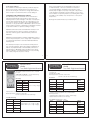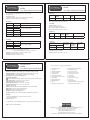
1
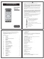
GENERAL SAFETY INFORMATION: Always read before proceeding. MM84 MULTIMETER Warning These instructions contain both information and warnings that are necessary for the safe operation and maintenance of this product. It is recommended that you read the instructions carefully and ensure that the contents are fully understood. Failure to understand and to comply with the warnings and instructions can result in serious injury, damage or even death. Instruction Manual In order to avoid the danger of electrical shock, it is important that proper safety measures are taken when working with voltages exceeding 30V AC rms, 42V AC peak or 60V DC. This product must only be used by a competent person capable of interpreting the results under the conditions and for the purposes for which it has been constructed. Particular attention should be paid to the Warnings, Precautions and Technical Specifications. Always check the unit is in good working order before use and that there are no signs of damage to it. Do not use if damaged. Where applicable other safety measures such as use of protective gloves, goggles etc. should be employed. Please keep these instructions for future reference. Updated instructions and product information are available at: www.martindale-electric.co.uk REMEMBER: SAFETY IS NO ACCIDENT MEANING OF SYMBOLS: Equipment complies with relevant EU Directives End of life disposal of this equipment should be in accordance with relevant EU Directives Caution - risk of electric shock Caution - risk of danger & refer to instructions Equipment protected by double or reinforced insulation (Class II) Direct current (DC) Alternating current (AC) Earth (ground) M84 instructions.indd 2 03/07/2012MM84 15:48:29 instructions.indd 3 1. INTRODUCTION 1.1 Inspection Examine the shipping carton for any sign of damage. Inspect the unit and any accessories for damage. If there is any damage then consult your distributor immediately. Thank you for buying one of our products. For safety and full understanding of its benefits please read this manual before use. Technical support is available from 01923 441717 and [email protected]. CONTENTS 11 Introduction 1.1 Inspection 1.2 Description 1.3 Accessories 2 Product Specific Safety Information 2.1 Precautions 3 Operation 3.1 General 3.2 Low Battery Indication 3.3 Description of Terminals 3.4 Description of Press Buttons 3.5 Description of LCD Symbols 3.6 Incorrect Connection Warning 3.7 Auto Power Off 3.8 Data Hold 3.9 AC & DC Voltage Measurement 3.10 AC & DC Current Measurement 3.11 Resistance Measurement 3.12 Frequency Measurement 3.13 Duty Cycle Measurement 3.14 Continuity Testing 3.15 Diode Testing 3.16 Logic Testing 4 Maintenance 4.1 Battery Replacement 4.2 Fuse Replacement 4.3 Test Lead Replacement 4.4 Calibration 4.5 Cleaning 4.6 Repair & Service 4.7 Storage Conditions 5 Warranty Specifications 03/07/2012 15:48:29 1 1 1 1 2 2 4 4 4 4 4 5 5 5 5 5 6 6 6 6 7 7 7 8 8 8 9 9 9 9 10 10 1.2 Description The MM84 is a 4½ digit multimeter with the following functions: True rms AC voltage to 750V DC voltage to 1000V True rms AC current to 20 A DC current to 20A Resistance to 20M: Frequency to 200kHz Continuity with audible indication Diode testing Duty cycle Logic test Further functions are: Data hold Auto power off Incorrect connection warning 1.3 Accessories (included) TL16 test leads Holster 9V battery (installed) Instructions 1.4 Battery Installation Refer to section 4.1 (Battery Replacement) for the battery installation instructions for the MM84. 1 2. PRODUCT SPECIFIC SAFETY INFORMATION Warning When using test leads, always keep your fingers behind the finger guard on the test lead probe. Measurement Category II (CAT II) is applicable to test and measuring equipment connected directly to utilization points (socket outlets and similar points) of the low-voltage MAINS installation. Warning Measuring a voltage that exceeds the specified limits of the unit may damage the unit and expose the operator to a shock hazard. Always check the unit’s specified limits before use. 2.1 Precautions This product has been designed with your safety in mind, but please pay attention to the following warnings and cautions before use. Caution Avoid severe mechanical shock or vibration and extreme temperature. Warning Before use check the unit for cracks or any other damage. Make sure the unit is free from dust, grease and moisture. Also check any associated leads and accessories for damage. Do not use if damaged. Caution Remove the batteries when not in use for an extended period, to avoid corrosion from leaking batteries. Warning Do not use if the rear casing is not fitted. Warning When this unit is used in combination with test leads, the measurement category of the combination is the lower measurement category of either this unit or the test leads used. Likewise if test lead accessories such as crocodile clips are also used, the measurement category will be the lowest measurement category in that combination. Warning Always test this unit on an appropriate proving device or known voltage source before and after using it to determine if a hazardous voltage exists in a circuit to be tested. 2 M84 instructions.indd 4 3 03/07/2012MM84 15:48:30 instructions.indd 5 3. OPERATION 03/07/2012 15:48:30 3.5 Description of LCD Symbols Diode testing function is selected H Auto hold is selected LOGIC Logic function is selected % Duty cycle function is selected mV, V, Units of measurement being displayed μA, mA, :, k:, M:, kHz Indicates battery is low AC Indicates AC measurement range selected DC Indicates DC measurement range selected 3.1 General If the multimeter does not measure current on the μA/mA ranges, the internal fuse (F1) may have blown (see section 4.2 Fuse Replacement). If the multimeter does not measure current on the 20A range the internal fuse (F2) may have blown (see section 4.2 Fuse Replacement). If the magnitude of a parameter to be measured is unknown, but known to be within the maximum safe limits of the multimeter, then manually set the range to maximum. For example if measuring DC voltage and the voltage magnitude is unknown, set the range to 1000V, then if required select autoranging for a satisfactory reading. 3.6 Incorrect Connection Warning If a test lead is connected to the μA mA or 20A input sockets when a voltage range is selected then a warning buzzer will sound. If the multimeter displays 1 with all other digits remaining blank then the measurement limits of the range have been exceeded. 3.7 Auto Power Off The MM84 will auto power off after approximately 45 minutes of inactivity. 3.2 Low Battery Indication If the symbol is displayed then the battery needs replacing (see section 4.1 Battery Replacement). 3.8 Data Hold To hold a displayed value press the DATA HOLD button. The LCD will display H . 3.3 Description of Terminals 20A Input terminal for AC & DC current measurements to 20A μA mA Input terminal for AC & DC current measurements to 200mA COM Common terminal for all measurements. Input terminal for AC & DC voltage, resistance, continuity, V:Hz diode, frequency, duty cycle and logic measurements. To exit display hold press the DATA HOLD button again. } 3.9 AC & DC Voltage Measurement Connect the black test lead to the COM terminal and the red test lead to the %HzV: terminal. and the required range. Set the rotary switch to either V~ or V Taking all necessary safety precautions connect the test leads to the circuit being measured and read the measured voltage from the display. 3.4 Description of Press Buttons POWER Switches on/off the MM84 DATA HOLD Activates/deactivates the data hold function 4 5 3.14 Continuity Testing Connect the black test lead to the COM terminal and the red test lead to the %HzV: terminal. 3.10 AC & DC Current Measurement Connect the black test lead to the COM terminal and the red test lead to the μA mA or 20A terminal depending on the magnitude of current to be measured. A A Set the rotary switch to either or and the required range. Taking all necessary safety precautions connect the test leads in series with the circuit being measured and read the measured current from the display. . Set the rotary switch to Taking all necessary safety precautions connect the test leads to the circuit being tested. The buzzer will sound if the resistance is <150:. 3.15 Diode Testing If the diode to be tested is in circuit be sure the circuit power is switched off. Connect the black test lead to the COM terminal and the red test lead to the %HzV: terminal. Set the rotary switch to . Taking all necessary safety precautions connect the test leads to the diode being tested. If the diode is good a forward bias will give a display reading of around 0.6V (silicon diode) and a reverse bias will give a display of OL. If the diode is shorted or open circuit the display will indicate approx 0V or OL respectively for both forward and reverse bias. 3.11 Resistance Measurement Connect the black test lead to the COM terminal and the red test lead to the %HzV: terminal. Set the rotary switch to : and the required range. Taking all necessary safety precautions connect the test leads to the circuit being measured and read the measured resistance from the display. 3.12 Frequency Measurement Connect the black test lead to the COM terminal and the red test lead to the %HzV: terminal. Set the rotary switch to Hz and the required range. Taking all necessary safety precautions connect the test leads to the circuit being measured and read the measured frequency from the display. 3.16 Logic Testing Connect the black test lead to the COM terminal and the red test lead to the %HzV: terminal. LOGIC. The LCD will display LOGIC. Set the rotary switch to Taking all necessary safety precautions connect the test leads to the circuit being tested. A logic 0 (Lo) will be indicated by a on the display. A logic 1 (Hi) will be indicated by a on the display and the MM84 buzzer will sound. 3.13 Duty Cycle Measurement Connect the black test lead to the COM terminal and the red test lead to the %HzV: terminal. Set the rotary switch to DUTY%. Taking all necessary safety precautions connect the test leads to the circuit being measured and read the measured % duty cycle from the display. 6 M84 instructions.indd 12 7 03/07/2012MM84 15:48:30 instructions.indd 13 4. MAINTENANCE 03/07/2012 15:48:30 Replace F1 only with the original type F500mA/600V, fast acting ceramic fuse and replace F2 only with the original type F20A/600V High Energy, fast acting ceramic fuse. Replace the rear casing and screws. 4.1 Battery Replacement To avoid shock or injury, disconnect the multimeter from any external circuits or components and remove the test leads before proceeding. 4.3 Test Lead Replacement If the test leads become damaged they should be replaced. The battery is replaced by removing the rear casing of the MM84. The rear casing is secured to the front by 3 screws and two internal snaps at the LCD end. The replacement test leads must have the same (or better) overvoltage category rating as the TL16 leads supplied. 4.4 Calibration To maintain the integrity of measurements made using your instrument, Martindale Electric recommends that it is returned at least once a year to an approved Calibration Laboratory for recalibration and certification. Remove the rear casing by removing the three screws from the rear casing. Gently lift the input terminal end of the rear casing until it unsnaps from the casing top. Fit a new 9V, NEDA 1604, JIS006P, IEC 6F22 battery observing correct polarity. Martindale Electric is pleased to offer you this service. Please contact our Service Department for details. Email: [email protected] Tel: 01923 650660 NOTE: It is essential to transfer the protective insulating sleeve from the old battery to the new battery. Replace the rear casing by snapping it into position and re-install the three screws. 4.5 Cleaning The unit may be cleaned using a soft dry cloth. Do not use moisture, abrasives, solvents, or detergents, which can be conductive. 4.2 Fuse Replacement 4.6 Repair & Service There are no user serviceable parts in this unit other than those that may be described in section 4. Return to Martindale Electric if faulty. Our service department will quote promptly to repair any fault that occurs outside the guarantee period. To avoid shock, injury or damage to the multimeter, disconnect the multimeter from any external circuits or components and remove the test leads before proceeding. Replace only with the fuse specified. The fuses are replaced by removing the rear casing of the MM84. Follow the procedure of section 4.1 (Battery Replacement) to remove the rear casing. Before the unit is returned, please ensure that you have checked the unit, fuses, test leads and battery. 8 9 4.7 Storage Conditions The instrument should be kept in warm dry conditions away from direct sources of heat or sunlight, and in such a manner as to preserve the working life of the unit. It is strongly advised that the unit is not kept in a tool box where other tools may damage it. Since some jurisdictions do not allow limitation of the term of an implied warranty, or exclusion or limitation of incidental or consequential damages, the limitations and exclusions of this warranty may not apply to every buyer. If any part of any provision of this warranty is held invalid or unenforceable by a court or other decision-maker of competent jurisdiction, such holding will not affect the validity or enforceability of any other provision or other part of that provision. 5. WARRANTY AND LIMITATION OF LIABILITY This Martindale product is warranted to be free from defects in material and workmanship under normal use and service. The warranty period is 2 years and begins on the date of receipt by the end user. This warranty extends only to the original buyer or enduser customer, and does not apply to fuses, disposable batteries, test leads or to any product which, in Martindale’s opinion, has been misused, altered, neglected, contaminated, or damaged by accident or abnormal conditions of operation, handling or storage. Nothing in this statement reduces your statutory rights. Martindale authorised resellers shall extend this warranty on new and unused products to end-user customers only but have no authority to extend a greater or different warranty on behalf of Martindale. Martindale’s warranty obligation is limited, at Martindale’s option, to refund of the purchase price, free of charge repair, or replacement of a defective product which is returned to Martindale within the warranty period. This warranty is the buyer’s sole and exclusive remedy and is in lieu of all other warranties, expressed or implied, including but not limited to any implied warranty of merchantability or fitness for a particular purpose. Martindale shall not be liable for any special, indirect, incidental or consequential damages or losses, including loss of data, arising from any cause or theory. 10 M84 instructions.indd 10 11 03/07/2012MM84 15:48:30 instructions.indd 7 03/07/2012 15:48:30 Specication MM84 True RMS Digital Multimeter ELECTRICAL SPECIFICATIONS All specified accuracies are at 23°C ± 5°C, <75% RH for 1 year Temperature Coefficient: 0.1 x (specified accuracy) per °C. (0°C to 18°C, 28°C to 50°C) DC Voltage Range Resolution 200mV 0.01mV 2V 0.0001V 20V 0.001V 200V 0.01V 1000V 0.1V Accuracy ± (0.05 % of rdg + 3 dgts) Input impedance: 10M: Overload protection: 1000V DC or 750 AC rms 500V DC or 350 AC rms on the 200mV range True RMS AC Voltage Range Resolution 200mV 0.01mV 2V 0.0001V 20V 0.001V 0.01V 200V 750V 0.1V Accuracy Specication MM84 True RMS Digital Multimeter AC coupled true rms specified from 5% to 100% of range Crest factor: d3 Input impedance: 10M: Overload protection: 1000V DC or 750 AC rms 500V DC or 350 AC rms on 200mV range DC Current Range Resolution Accuracy Voltage Burden 200μA 0.01μA ± (0.5 % of rdg + 5 dgts) 300mV 2mA 0.0001mA 300mV 20mA 0.001mA 300mV 200mA 0.01mA 600mV 20A * 0.001A 50Hz to 500Hz ± (2.0 % of rdg + 20 dgts) 800mV * Current on 10 A range applied for 30 seconds maximum Overload protection: 0.5A/600V fast blow ceramic fuse on 200μA to 200mA ranges 20A/600V fast blow ceramic fuse on 20A range True RMS AC Current (50Hz to 1kHz) Range 50Hz to 500Hz ± (1.0 % of rdg + 10 dgts) 500Hz to 2kHz ± (2.0 % of rdg + 20 dgts) ± (2.0 % of rdg + 10 dgts) Resolution Accuracy Voltage Burden 200μA 0.01μA ± (0.8 % of rdg + 10 dgts) 300mV 2mA 0.0001mA 20mA 0.001mA 300mV 200mA 0.01mA 600mV 20A * 0.001A 300mV ± (2.5 % of rdg + 10 dgts) 800mV Specication MM84 True RMS Digital Multimeter Specication MM84 True RMS Digital Multimeter * Current on 10 A range applied for 30 seconds maximum AC coupled true rms specified from 5% to 100% of range. Crest factor: d 3. Overload protection: 0.5A/600V fast blow ceramic fuse on 200μA to 200mA ranges 20A/600V fast blow ceramic fuse on 20A range Duty Cycle Range Frequency Range Resolution Pulse Width Accuracy (5V Logic) 0% to 90% 20Hz to 20kHz 0.1 % >10 us ±(2.0% rdg + 10 dgts) Overload protection: 500V DC or AC rms Resistance Range Resolution Accuracy 200: 0.01: ± (0.25% of rdg + 10 dgts) 2k: 0.0001k: 20k: 0.001k: 200k: 0.01k: 2M: 0.0001M: Continuity Audible indication: <150: Response time: Approx 500ms Open circuit voltage: 3.3V DC approx Overload protection: 500V DC or AC rms ± (0.15% of rdg + 3 dgts) Diode Test ± (0.25% of rdg + 10 dgts) 20M: 0.001M: ± (1.0% of rdg + 10 dgts) Open circuit voltage: 3.3V DC approx. Overload protection: 500V DC or AC rms. Range Resolution Test Current Open Circuit Voltage Accuracy 2V 0.1mV 1.0 mA 3.3V DC approx ± (0.5% rdg + 1 dgt) Overload protection: 500V DC or AC rms Frequency Range Resolution 2 kHz 0.1 Hz 20 kHz 1 Hz 200 kHz 10 Hz Logic Test Accuracy Thresholds ± (0.5 % of rdg + 3 dgts) Logic 1 (Hi) Logic 0 (Lo) 2.8V ± 0.8V 0.8V ± 0.5V Pulse Rise Time (Max) Pulse Repetition Rate (Max) Pulse Width (Min) 10μs 1 Mpps 25ns Duty cycle: > 20% and < 80% Frequency response: 20 MHz Overload protection: 500V DC or AC rms Input sensitivity: 50mV rms minimum for sine wave 400mV rms minimum at >30% and <70% duty cycle Minimum input: 22Hz range > 2Hz, 220Hz range > 20Hz Minimum pulse width: >2μs at >10Hz Overload protection: 500V DC or AC rms 1 M84 instructions.indd 2 03/07/2012MM84 15:48:29 instructions.indd 5 Specication MM84 True RMS Digital Multimeter GENERAL SPECIFICATIONS Display: 4½ digit liquid crystal display with a maximum reading of 19999 Analog bargraph: 22 segments with measurement 20 times per second Polarity: Automatic, positive implied, negative polarity indication Overrange: Most significant digit displays “1” Low battery indication: symbol is displayed when the battery voltage drops below the operating level Measurement rate: 2.5 times per second, nominal Auto power off: After approx 45 minutes Operating environment: 0°C to 50°C at < 70% RH Storage temperature: -20°C to 60°C at < 80% RH Altitude: Up to 2000m Power: Single standard 9 volt battery, NEDA 1604, JIS006P, IEC 6F22 Battery Life: 300 hours typical with carbon-zinc Dimensions: 189 (H) x 87 (W) x 37 mm (D) Weight: 330g approx. including battery Includes: TL16 test leads, holster, 9V battery (installed) and instructions. 03/07/2012 15:48:29 Check out what else you can get from Martindale: • • • • • • • • • • • • 17th Edition Testers Accessories Calibration Equipment Continuity Testers Electricians’ Kits Environmental Products Full Calibration & Repair Service Fuse Finders Digital Clamp Meters Digital Multimeters Labels Microwave Leakage Detectors • • • • • • • • • • • • Motor Maintenance Equipment Multifunction Testers Non-trip Loop Testers Pat Testers & Accessories Phase Rotation Testers Proving Units Socket Testers Thermometers & Probes Test Leads Voltage Indicators Specialist Metrohm Testers (4 & 5kV) Specialist Drummond Testers SAFETY: Conforms to BS EN61010-1, CAT II 1000V DC, 750V AC Class II Double Insulation Pollution Degree: 2 TL16 test leads conform to BS EN61010-031, CAT III 1000V, CAT IV 600V, 10A EMC: Conforms to BS EN 61326 Martindale Electric Company Limited Metrohm House, Penfold Trading Estate, Imperial Way, Watford WD24 4YY, UK Tel: +44(0)1923 441717 Fax: +44 (0)1923 446900 E-mail: [email protected] Website: www.martindale-electric.co.uk © 2012 Martindale Electric Company Ltd. Registered in England No. 3387451. E. & O.E. Document Rev1 LITMM84