1
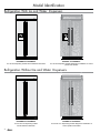
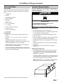
Installation Instructions Built-In Refrigerator 42 and 48 Inch Models: EF42DBSS, EF42NBSS, EF48DBSS, EF48NBSS Part No. 103675 Rev. E/W10159564E IF42DBOL, IF42NBOL, IF48DBOL, IF48NBOL Table of Contents Refrigerator Safety........................................................................1 Model Identification.......................................................................2 Installation Requirements.......................................................3-12 Tools and Parts............................................................................ 3 Location Requirements.............................................................3-4 Electrical Requirements...............................................................4 Water Supply Requirements........................................................ 5 Tipping Radius.............................................................................5 Product Dimensions.....................................................................6 Door Swing Dimensions.............................................................. 7 Door Panels and Cabinetry Clearance.....................................8-9 Custom Panels and Handles................................................ 10-11 Custom Side Panels.............................................................12-13 Installation Instructions.........................................................14-21 Unpack Refrigerator...................................................................14 Reduce Tipping Radius............................................................. 14 Move Refrigerator into House....................................................14 Install Anti-Tip Boards................................................................ 15 Connect Water Supply..........................................................15-16 Plug in Refrigerator.................................................................... 16 Move to Final Location.............................................................. 16 Level and Align Refrigerator...................................................... 17 Custom Panel and Handle Installation .....................................18 Adjust Doors..............................................................................19 Install Side Panel(s)................................................................... 20 Install Base Grille....................................................................... 20 Complete Installation.................................................................21 Water System Preparation......................................................... 21 Notes.........................................................................................22 Français...................................................................................23-44 Customer Service Information If you have questions or problems with installation, contact your Dacor ® dealer or the Dacor Customer Service Team. When you call, have the model and serial number of the appliance ready. The model and serial number are printed on the appliance data label. The label is located inside the refrigerator on the right. Dacor Customer Service Phone: (800) 793-0093 Web site: www.Dacor.com All specifications subject to change without notice. Dacor assumes no liability for changes to specifications. © 2008 Dacor, all rights reserved. Refrigerator Safety Your safety and the safety of others are very important. We have provided many important safety messages in this manual and on your appliance. Always read and obey all safety messages. This is the safety alert symbol. This symbol alerts you to potential hazards that can kill or hurt you and others. All safety messages will follow the safety alert symbol and either the word “DANGER” or “WARNING.” These words mean: DANGER WARNING You can be killed or seriously injured if you don't immediately follow instructions. You can be killed or seriously injured if you don't follow instructions. All safety messages will tell you what the potential hazard is, tell you how to reduce the chance of injury, and tell you what can happen if the instructions are not followed. WARNING Tip Over Hazard Refrigerator is top heavy and tips easily when not completely installed. Keep doors taped closed until refrigerator is completely installed. Use two or more people to move and install refrigerator. Failure to do so can result in death or serious injury. 1 Model Identification Refrigerators With Ice and Water Dispensers EF42DBSS and EF48DBSS: 42” and 48” dispensing models with all stainless steel finish IF42DBOL and IF48DBOL: 42” and 48” dispensing models designed for installation of custom panels and handles Refrigerators Without Ice and Water Dispensers EF42NBSS and EF48NBSS: 42” and 48” non-dispensing models with all stainless steel finish 2 IF42NBOL and IF48NBOL: 42” and 48” non- dispensing models designed for installation of custom panels and handles Installation Requirements Tools and Parts Location Requirements Tools needed: Your Dacor refrigerator can be recessed in an opening between cabinets or installed at the end of a cabinet run using a side panel to enclose the refrigerator. Gather the required tools and parts before starting installation. Read and follow the instructions provided with any tools listed here. Cordless drill Drill bits WARNING Two adjustable wrenches Phillips screwdriver Small level Explosion Hazard Appliance dolly Torx ®† T27 screwdriver ¹¹⁄32” nut driver ³⁄8” and ¹⁄2” open-end wrenches Keep flammable materials and vapors, such as gasoline, away from refrigerator. Failure to do so can result in death, explosion, or fire. Allen wrench (5⁄32”) IMPORTANT: ¹⁄4” and 5/16” socket drivers Observe all governing codes and ordinances. Tape measure Parts Needed: It is recommended that you do not install the refrigerator near an oven, radiator, or other heat source. Six #8 x 3” (7.6 cm) wood screws (longer screws may be needed) Do not install in a location where the temperature will fall below 55°F (13°C). One or two 2” x 4” x 32” (5 cm x 10 cm x 81 cm) wood board(s) Floor must support the refrigerator weight, more than 600 lbs (272 kg), door panels and contents of the refrigerator. IF Series Models: Make custom panels, or consult a qualified cabinetmaker or carpenter to make the panels. See “Installation Requirements” for more information. Ceiling height must allow for side tipping radius. See Tipping Radius. EF Series Models: Comes with doors that have a stainless steel finish and are shipped complete. If you are connecting the water line directly to copper tubing and not to a shutoff valve, you need a ferrule, a union, and a ¹⁄4” (6.35 mm) compression fitting. Location should permit doors to open fully. See Door Swing Dimensions. Location must permit top grille removal. See Opening Dimensions. Opening Dimensions To avoid tipping during use, the solid soffit must be within 1” (2.5 cm) maximum above the refrigerator. If the solid soffit is higher than 1” (2.5 cm) or one is not available, then the refrigerator must be braced. If the anti-tip boards are needed, they must be attached to the rear wall studs 80” to 90” (203 cm to 229 cm) above the floor. See Install Anti-Tip Boards for more information. NOTE: A clearance of ¹⁄2” (1.3 cm) must be maintained above the top grille in order for the top grille to be removed. 1/2” (1.3 cm) † TORX is a registered trademark of Textron Innovations Inc. 3 Installation Requirements Location Requirements (continued) Electrical Requirements A grounded 3 prong electrical outlet should be placed within 4” (10.2 cm) of the right side cabinets or end panel. See Electrical Requirements for more information. WARNING The water shutoff should be located in the base cabinet on either side of the refrigerator or some other easily accessible area. If the water shutoff valve is not in the cabinets, the plumbing for the water line can come through the floor or the back wall. See Water Supply Requirements for more information. Electrical Shock Hazard Plug into a grounded 3 prong outlet. Do not remove ground prong. Do not use an adapter. Do not use an extension cord. Failure to follow these instructions can result in death, fire, or electrical shock. 4” (10.2 cm) Before you move your refrigerator into its final location, it is important to make sure you have the proper electrical connection. 83 1/2” (212.1 cm) min. 84 3/4” (215.2 cm) to bottom of solid soffit Recommended Grounding Method A 115 Volt, 60 Hz., AC only 15 or 20-amp fused, grounded electrical supply is required. It is recommended that a separate circuit serving only your refrigerator be provided. Use an outlet that cannot be turned off by a switch. Do not use an extension cord. 77” (195.6 cm) IMPORTANT: If this product is connected to a GFCI (Ground Fault Circuit Interrupter) equipped outlet, nuisance tripping of the power supply may occur, resulting in loss of cooling. Food quality and flavor may be affected. If nuisance tripping has occurred, and if the condition of the food appears poor, dispose of it. A Width (see chart following) NOTE: Before performing any type of installation, cleaning, or removing a light bulb, remove the top grille and turn the master power switch to OFF or disconnect power at the circuit breaker box. See page 5 24” (61.0 cm) min. Model Series Cutout Width A EF42, IF42 41½” (105.4 cm) to 41¾” (106.1 cm) EF48, IF48 47½” (120.7 cm) to 47¾” (121.3 cm) NOTE: Flooring under refrigerator must be at same level as the room. Face of cabinetry must be plumb. 4 When you are finished, turn ON the main power switch or reconnect power at the circuit breaker box. Then reset the control to the desired setting. Installation Requirements Water Supply Requirements If the water pressure to the reverse osmosis system is less than 40 to 60 psi (276 to 414 kPa): All installations must meet local plumbing code requirements. Check to see whether the sediment filter in the reverse osmosis system is blocked. Replace the filter if necessary. The water shutoff should be located in the base cabinet on either side of the refrigerator or some other easily accessible area. The right-hand side is recommended. The access hole through the cabinet must be within ½” (12.7 mm) of the rear wall. NOTE: If the water shut off valve is in the back wall behind the refrigerator, it must be at an angle so that the tube is not kinked when the refrigerator is pushed into its final position. Access hole with 1/2” (1.3 cm) of floor and rear wall Allow the storage tank on the reverse osmosis system to refill after heavy usage. If your refrigerator has a water filter cartridge, it may further reduce the water pressure when used in conjunction with a reverse osmosis system. Remove the water filter cartridge. If you have questions about your water pressure, call a licensed, qualified plumber. Tipping Radius Be sure there is adequate ceiling height to stand the refrigerator upright when it is moved into place. The dolly wheel height must be added to the tipping radius when a dolly is used. Possible water line locations If needed, the tipping radius can be reduced. See Reduce Tipping Radius. Side Tipping Radius 6” (15.2 cm) 1” (2.5 cm) 6” (15.2 cm) The side tipping radius varies depending upon the width of the model. Use the chart provided to determine the side tipping radius. NOTE: Tip on side only. If the water shutoff valve is not in the cabinets, the plumbing for the water line can come through the floor. A ½” (12.7 mm) hole for plumbing should be drilled at least 6” (15.2 cm) from the right or left hand side cabinet or panel. On the floor, the hole should be no more than 1” (2.54 cm) away from the back wall. See Connect the Water Supply. If additional tubing is needed, use copper tubing and check for leaks. Install the copper tubing only in areas where the household temperatures will remain above freezing. Do not use a piercing-type or ³⁄16” (4.76 mm) saddle valve which reduces water flow and clogs more easily. NOTE: Your refrigerator dealer has a kit available with a ¼” (6.35 mm) saddle-type shutoff valve, a union and copper tubing. Before purchasing, make sure a saddle-type valve complies with your local plumbing codes. Water Pressure A cold water supply with water pressure between 30 and 120 psi (207 and 827 kPa) is required to operate the water dispenser and ice maker. If you have questions about your water pressure, call a licensed, qualified plumber. A A Model Series Tipping Radius A EF42, IF42 93” (236.2 cm) EF48, IF48 96” (243.8 cm) Reverse Osmosis Water Supply IMPORTANT: The pressure of the water supply coming out of a reverse osmosis system going to the water inlet valve of the refrigerator needs to be between 30 and 120 psi (207 and 827 kPa). If a reverse osmosis water filtration system is connected to your cold water supply, the water pressure to the reverse osmosis system needs to be a minimum of 40 to 60 psi (276 to 414 kPa). 5 Installation Requirements Product Dimensions Side View: Front View: The depth from the front of the top grille to the back of the refrigerator cabinet is 25³⁄8” (64.5 cm). Width dimensions were measured from trim edge to trim edge. The power cord is 84” (213 cm) long. The water line attached to the back of the refrigerator is 5 ft (1.5 m) long. Height dimensions are shown with leveling legs extended ¹⁄8” (3 mm) below the rollers. Height dimensions are shown with leveling legs extended ¹⁄8” (3 mm) below the rollers. 25 3/8” (64.5 cm) 23 1/2” (59.7 cm) *83 3/8” (211.8 cm) *83 3/8” (211.8 cm) 84” (213.4 cm) Power Cord B (see following chart) *3 1/2” (8.9 cm) * When leveling legs are fully extended to 1¼” (3.2 cm) below rollers, add 1¹⁄8” (2.9 cm) to the height dimensions. Top View: A 25 3/8” (64.5 cm) 6 Model Width A EF42, IF42 41 ¼” (104.8 cm) EF48, IF48 47 ¼” (120.0 cm) Model Series Width B (Trim edge to trim edge) EF42, IF42 42 ¼” (107.3 cm) EF48, IF48 48 ¼” (122.6 cm) *When leveling legs are fully extended to 1¼” (3.2 cm) below rollers, add 1¹⁄8” (2.9 cm) to the height dimensions. Installation Requirements Door Swing Dimensions The location must permit both doors to open to a minimum of 90°. Allow 4½” (11.4 cm) minimum space between the side of the refrigerator and a corner wall. NOTE: More clearance may be required if you are using overlay panels, custom handles or extended handles on a IF series model. To adjust the door swing, see Adjust Doors. EF42 and IF42 Model Series 17¹⁄ 2 " (44.5 cm) 42 9⁄16 " (108.1 cm) 38" (96.5 cm) 23 ¹⁄4" (59.1 cm) 47" (119.4 cm) 41" (104.1 cm) 90˚ 110˚ 130˚ 90˚ 110˚ 130˚ EF48 and IF48 Model Series 19 ³⁄4 " (50.2 cm) 45¹⁄4 " (114.9 cm) 40" (101.6 cm) 26 ³⁄4 " (68.0 cm) 50¹⁄2 " (128.3 cm) 43¹⁄2 " (110.5 cm) 90˚ 110˚ 130˚ 90˚ 110˚ 130˚ 7 Installation Requirements Door Panels and Cabinetry Clearance - IF42/IF48 Series Models The custom door panels and adjacent cabinetry for models series IF42 and IF48 must be designed so that there is sufficient clearance for the doors to swing open. If the refrigerator is to be installed close to the wall, see Door Swing 90° on facing page. Door Swing 110° Actual Size Refrigerator to Cabinetry Clearance Refrigerator Side Trim 11/2" (3.8 cm) 11/4" (3.2 cm) 1" (2.5 cm) Cabinetry 110˚ Door Stop Position /4" (6.4 mm) 1 Hinge / " (1.3 cm) 1 2 / " (1.9 cm) 3 4 1" (2.5 cm) 1/2" (1.3 cm) 3 /4" (1.9 cm) 1" (2.5 cm) rlay Ove 11/4" (3.2 cm) 11/2" (3.8 cm) l e Pan r el Pan ker Bac Doo NOTE: For IF Series models, rout the hinge side of the custom door panels to a radius that is equal to at least half the thickness of the panel if a 130° door swing is desired. See Adjust Doors. Spacer Panel When the doors are closed the refrigerator will extend beyond the face of the adjacent cabinetry to some degree. 8 Installation Requirements Door Swing 90° Actual Size Door Swing 90˚ Actual Size Refrigerator to Cabinetry Clearance Refrigerator to Cabinetry Clearance Refrigerator Side Trim 1" (2.5 cm) 3/4" (1.9 cm) 1/2" (1.3 cm) 90° Door Stop Position Cabinetry 1/4" Hinge (6.4 mm) 1/2" (1.3 cm) 3/4" (1.9 cm) 1" (2.5 cm) Door Overlay Panel Backer Panel 1/2" (1.3 cm) 3/4" (1.9 cm) 1" (2.5 cm) 11/4" (3.2 cm) 11/2" (3.8 cm) Spacer Panel Allow a minimum of 4½” (11.4 cm) of space between the side of the refrigerator and a corner wall. More clearance may be needed if thicker custom panels or custom handles are used. Do not overlook baseboards. 9 Installation Requirements Custom Panels and Handles - IF42/IF48 Series Models Custom overlay panels used with models IF42 and IF48 allow you to blend the exterior of your refrigerator into the overall kitchen décor, and to use custom handles for additional design flexibility. Important Information About Freezer Door Overlay Panels on Dispenser Models: • There are two basic methods for paneling the freezer door on dispenser models: Panel Specifications -- Frameless method • The custom panels must have backer panels attached in order to mount them to the refrigerator. It is most common to work with three layers, as shown in the illustrations below. The three layers consist of a decorative overlay panel, a ¹/8” (3.18 mm) spacer panel or spacer strips and a ¼” (6.35 mm) backer panel. -- Framed method • The framless method involves fabricating two separate panels for above and below the dispenser that slide in from the handle side of the door. • In some cases, instead of constructing the panel using three layers, the cabinet manufacturer may choose to work with a single piece routed for the different dimensions. Follow the panel dimension and placement instructions on the facing page to be sure that the custom overlay panels will fit properly. • The framed method involves fabricating a single overlay panel and attaching two separate sets of spacer and backer panels above and below the dispenser cutout (see facing page). The completed panel slides into place as a single unit. IMPORTANT: The dispenser is recessed behind the overlay panel for the freezer door. The edges of the overlay panel around the bottom of the dispenser may be exposed to water during normal use. Seal the area around the dispenser to prevent water seepage and damage. It is suggested that the edges of the panel around the bottom the dispenser be covered by waterproof material to prevent damage to the finish over time. • To minimize panel weight, you may use 2” (5.08 cm) spacer strips around the perimeter in place of full-sheet solid spacer panels. The spacer strips must be set in at least 1” (2.54 cm) from the top, bottom and side edges of the backer panel. If you use spacer strips, it is also recommended that you use two 2” (5.08 cm) strips horizontally centered for added support. • For the grille and the door panels to be flush, the overlay door panel should be ¼” (6.35 mm) thicker than the overlay grille panel. IMPORTANT: • Install the custom panels only after moving the refrigerator into place (see page 16). • The weight of the overlay panels cannot exceed: -- 50 lbs (23 kg) for the refrigerator door -- 30 lbs (13.5 kg) for the freezer door (total) -- 10 lbs (4.5 kg) for the top grille Overlay Panel Overlay Panel Spacer Panel Spacer Panel Spacer Panel 1/8" (3.2 mm) Backer Panel Backer Panel 1/4" (1.6 to1.9 cm) 5/8 " to 3/4 " 1/8" (6.4 mm) 1/4" (1.6 to1.9 cm) (3.2 mm) 1/8" (6.4 mm) (3.2 mm) 5/8 " to 3/4 " 10 Spacer Panel 1/8" (3.2 mm) Overlay Panel Overlay Panel Backer Panel Backer Panel Door Door 1" minimum* 1" minimum* (2.5 cm) (2.5 cm) Door/Grille Trim Offset Dimension Door/Grille Trim Offset Dimension * The spacer panel offset must be a minimum of 1” (2.5 cm) from all four edges of each backer panel, including the edges next to the dispenser (on dispenser models). Installation Requirements Freezer Panels for Dispenser Models Frameless Method Backer Top Offset 7 " (1.1 cm) ⁄16 A 24 ¹⁄8 " (61.1 cm) Backer Handle-Side Offset ¹⁄8 " (3.2 mm) 23 ⁄ " (59.4 cm) 38 Freezer Panel for Non-Dispenser Models Refrigerator Panel for all Models A B Framed Method A Backer Handle-Side Offset ¹⁄8 " (3.2 mm) 23 ⁄ " (59.4 cm) 38 D Backer Handle-Side Offset ¹⁄8 " (3.2 mm) D Top Freezer Panel Dispenser cutout is centered left to right A D 11 5⁄8 " (29.5 cm) 34 ³⁄8 " (87.3 cm) 15 D 70¹⁄2 " (179.1 cm) D E 35” (88.9 cm) 34 ³⁄8 " (87.3 cm) Bottom Freezer Panel 70¹⁄2 " (179.1 cm) 71¹⁄16 " (180.5 cm) Backer Handle-Side Offset ¹⁄8 " (3.2 mm) 35” (88.9 cm) 11 ⁄16 " (30.5 cm) Backer Bottom Offset ¹⁄8 " (3.2 mm) Backer Bottom Offset ¹⁄8 " (3.2 mm) Backer Bottom Offset ¹⁄8 " (3.2 mm) Decorative Overlay Panels Model Series A B C IF42 17¹⁄8” (43.5 cm) 23¹⁄8” (58.74 cm) 40½” (102.9 cm) IF48 19 5⁄8” (49.9 cm) 265⁄8” (67.6 cm) 46½” (118.1 cm) Model Series D E F IF42 16 7⁄8” (42.9 cm) 22 7⁄8” (58.1 cm) 40½” (102.9 cm) IF48 19 ⁄8” (49.2 cm) 26 ⁄8” (67.0 cm) 46½” (118.1 cm) 3 7 3/ 8" (18.7 cm) Custom Handles Dacor recommends handles with larger D-style pulls. If using screws with thick heads, they must be countersunk into the panel before installing the handles. Any handle designed for use with an appliance should produce satisfactory results. Mounting screw length varies with the total thickness of the panels. C Backer Bottom Offset 1" (2.5 cm) F 81/2" (21.6 cm) Backer Panels 3 Top Grille B A Trim frame surrounding door IMPORTANT: Dacor does not advise the use of single pull knobs. Door C 20” Typ. (50.6 cm) 36” Max. (91.4 cm) A. Countersunk screw B. Handle C. Door panel assembly Handle Detail 11 Installation Requirements Custom Side Panels - IF42/IF48 Inset Installation Dimensions Custom side panels may be needed when not enough space is available to have cabinets on both sides of the refrigerator or when the refrigerator is placed at the end of a cabinet run. You may choose an Inset or Recessed Inset panel installation for models IF42 and IF48. 1. Measure the distance from point A (as shown) to the back wall. Add ¹⁄32” (0.8 mm) to this measurement to allow the side panel to fit into the trim. 2. If the panel is more than ³⁄8” (9.5 mm) thick, rout the front edge to allow the side panel to fit into the trim. Refrigerator and Side Trim Dimensions The width and height of a side panel are determined by the type of installation you are planning. Back wall NOTES: The dimensions shown are actual product dimensions and may not reflect the needed installation dimensions. The side panel should be a minimum of ½” (1.3 cm) thick to avoid warping. If the opening depth is 25” (63.5 cm) or more, you may want to install a support board on the rear wall. Refrigerator A A Recessed Inset Installation Dimensions 1. Measure the distance from point B (as shown) to back wall. 23 1/2” (59.7 cm) 2. Route the front edge of the support board or attach a ³⁄8” (9.5 mm) board to hold the panel in the cabinet side trim. Back wall B A Side Trim 3/16” (4.5 mm) 3/8” (9.7 mm) 1/16” (1.5 mm) 1/8” (3.2 mm) 12 Installation Requirements Custom Side Panels - EF42/EF48 Inset Installation Dimensions Custom side panels may be needed when not enough space is available to have cabinets on both sides of the refrigerator or when the refrigerator is placed at the end of a cabinet run. You may choose an inset, flush or recessed inset panel installation for models EF42 and EF48. 1. Measure the distance from point A (as shown) to the back wall. Add 7⁄32” (5.6 mm) to this measurement to allow the side panel to fit into the trim. 2. If the panel is more than ¼” (6.4 mm) thick, route the front edge to allow the side panel to fit into the trim. Refrigerator and Side Trim Dimensions The width and height of a side panel are determined by the type of installation you are planning. Back wall NOTES: The dimensions shown are actual product dimensions and may not reflect the needed installation dimensions. A A The side panel should be a minimum of ½” (1.3 cm) thick to avoid warping. If the opening depth is 25” (63.5 cm) or more, you may want to install a support board on the rear wall. Refrigerator Flush Installation Dimensions 24 1/8” 24¹⁄ 8" (61.3 cm) (61.3 cm) 232311/16” ¹¹⁄16" (60.3 cm) (60.3 cm) ½" 231/2” 23 (59.7 cm) (59.7 cm) 1. Measure the distance from point B (as shown) to the back wall. 2. Attach the support board with a screw or adhesive that is compatible with aluminum and wood. Back wall Side Trim 1/4” (6.35 mm) 11/64” (4.5 mm) 3/16” (4.7 mm) B A Recessed Inset Installation Dimensions 1. Measure the distance from point C (as shown) to the back wall. 7/32” (5.5 mm) 13/32” (10 mm) 2. Route the front edge of the support board or attach a ¼” (6.4 mm) board to hold the panel in the cabinet side trim. 5/8” (15.7 mm) Back wall C A 13 Installation Instructions Unpack Refrigerator WARNING 1. Grasp both ends of the top grille. 2. Push the top grille straight up, then pull straight out. Lay the grille on a soft surface. B A B Tip Over Hazard Refrigerator is top heavy and tips easily when not completely installed. Keep doors taped closed until refrigerator is completely installed. A. Top grille B. Cabinet side trim 3. Remove the six screws attaching each cabinet side trim to the refrigerator and remove the side trims. Use two or more people to move and install refrigerator. Move Refrigerator into House Failure to do so can result in death or serious injury. WARNING IMPORTANT: If you receive a damaged product, immediately contact your dealer or builder. Do not install or use a damaged appliance. Do not remove the film on the outside until the refrigerator is in its operating position. All four leveling legs must contact the floor to support and stabilize the full weight of the refrigerator. Keep the cardboard shipping piece or plywood under the refrigerator until it is installed in the operating position. 1. Remove and save the literature package bag taped to the side of the refrigerator and the parts bag behind the grille. Remove the four brackets (two on each side) that attach the shipping base to the refrigerator bottom. NOTE: Do not remove tape and door bracing until the refrigerator is in its final position. 2. If necessary, reduce the tipping radius. See Tipping Radius (page 5) for ceiling height requirements or Reduce Tipping Radius for step-by-step instructions. If you do not need to reduce the tipping radius, proceed to Move the Refrigerator into House. Reduce Tipping Radius (if required) Before bringing the refrigerator into the home, be sure there is adequate ceiling height to stand the refrigerator upright. See Tipping Radius (page 5). If you do not have adequate ceiling height to stand the refrigerator upright, the tipping radius can be reduced by removing the top grille and side trims (see the following chart). Model Reduced Tipping Radius EF42, IF42 88½” (224.8 cm) EF48, IF48 89¼” (226.7 cm) Tip Over Hazard Refrigerator is top heavy and tips easily when not completely installed. Keep doors taped closed until refrigerator is completely installed. Use two or more people to move and install refrigerator. Failure to do so can result in death or serious injury. 1. Place an appliance dolly under the left side of the refrigerator as shown. Be sure to avoid damaging the side trims and handles. Place the corner posts from the packing materials over the trims and handles as appropriate. Slowly tighten the strap. NOTE: Pass the dolly strap under the handles for EF series models. 2. Place pieces of the shipping carton on the floor when rolling the dolly and refrigerator into the house. Move the refrigerator close to the built-in opening. 3. Place top of cardboard carton or plywood under refrigerator. 4. Stand the refrigerator up. First, place the left bottom edge of the refrigerator on the floor, stand the refrigerator upright and then lower the right-hand side of the refrigerator to the floor. 5. Do not remove the film on the outside. 6. Reassemble the trim and top grille after the dolly has been removed from the refrigerator. 14 Installation Instructions Install Anti-Tip Boards Connect Water Supply IMPORTANT: Read all directions before you begin. To avoid tipping during use, the solid soffit must be within 1” (2.5 cm) maximum above the refrigerator. If the solid soffit is higher than 1” (2.5 cm) or one is not available, then the refrigerator must be braced. IMPORTANT: If you turn the refrigerator on before the water line is connected, turn the ice maker OFF. It is recommended that board(s) be installed before the refrigerator is installed. NOTE: If your water line connection does not look like Style 1, see Style 2 - Copper Line Connection. Board(s) must be long enough to fully cover the width of the compressor cover. 1. Unplug refrigerator or disconnect power supply. Locate the board(s) so the bottom surface(s) of the board(s) is (are) 84” (213 cm) from the floor. During installation, raise the refrigerator up so there is ¼” (6.35 mm) maximum between the top of the refrigerator and the bottom of the anti-tip board(s). Do not crush the compressor cover when raising the rear leveling legs. To Install Anti-tip Boards 1. Mark the stud locations on rear wall 80” to 90” (203 cm to 229 cm) above floor. 2. Securely attach one or two 2” x 4” x 32” (5 cm x 10 cm x 81 cm) boards to wall studs behind refrigerator. Use six #8 x 3” (7.6 cm) (or longer) wood screws. The wood screws must be screwed into the studs at least 1½” (3.8 cm). The board(s) must overlap the compressor cover. A B Style 1 - Shutoff Valve Connection IMPORTANT: Before attaching the tubing to shutoff valve, flush the main water supply line to remove particles and air in the water line. Allow enough flow so that water becomes clear. Flushing the water line may help avoid filters and/or water valves from becoming clogged. 2. Remove the shipping tape from the gray, coiled water tubing on the rear of the refrigerator. 3. Thread the provided nut onto the shutoff valve as shown. 4. Turn shutoff valve ON. 5. Check for leaks. Tighten any nuts or connections (including connections at the valve) that leak. A B A. Bulb B. Nut C. Water tubing C 6. Plug in the refrigerator or reconnect power. 7. Flush the water system. See Water System Preparation. C 2” (5 cm) NOTE: Allow 24 hours to produce the first batch of ice. Discard the first three batches of ice produced. Allow 3 days to completely fill ice container. Style 2 - Copper Line Connection Connecting to Water Line NOTE: If existing water line meets the Water System Requirements, see Connecting to Refrigerator. 1. Unplug refrigerator or disconnect power. D A. Center board 1/4” (6.4 mm) max. above refrigerator B. Two 2” x 4” x 32” (5 cm x 10 cm x 81 cm) boards C. Attach to studs with six #8 x 3” (7.6 cm) screws D. Compressor cover 2. Turn OFF main water supply. Turn ON nearest faucet long enough to clear line of water. 3. Locate a ½” to 1¼” (1.25 cm to 3.18 cm) vertical cold water pipe near the refrigerator. IMPORTANT: Make sure it is a cold water pipe. Horizontal pipe will work, but drill on the top side of the pipe, not the bottom. Doing so will help keep water away from the drill and normal sediment from collecting in the valve. 4. Determine the length of copper tubing you need. Measure from the connection on the lower left rear of refrigerator to the water pipe. Add 7 ft. (2.1 m) to allow for cleaning. Use ¼” (6.35 mm) O.D. (outside diameter) copper tubing. Be sure both ends of copper tubing are cut square. 15 Installation Instructions 5. Using a cordless drill, drill a ¼” (6.35 mm) hole in the cold water pipe you have selected. 6. Check for leaks. Tighten any nuts or connections (including connections at the valve) that leak. 6. Fasten the shutoff valve to the cold water pipe with the pipe clamp. Be sure the outlet end is solidly in the ¼” (6.35 mm) drilled hole in the water pipe and that the washer is under the pipe clamp. Tighten the packing nut. Tighten the pipe clamp screws slowly and evenly so the washer makes a watertight seal. Do not overtighten. 7. Plug in the refrigerator or reconnect power. A C F E NOTE: Allow 24 hours to produce the first batch of ice. Discard the first three batches of ice produced. Allow 3 days to completely fill ice container. Plug in Refrigerator WARNING B G 8. Flush the water system. See Water System Preparation. D A. Cold water pipe B. Pipe clamp C. Copper tubing D. Compression nut E. Compression sleeve F. Shutoff valve G. Packing nut Electrical Shock Hazard Plug into a grounded 3 prong outlet. 7. Slip the compression sleeve and compression nut on the copper tubing as shown. Insert the end of the tubing into the outlet end squarely as far as it will go. Screw compression nut onto outlet end with adjustable wrench. Do not overtighten the nut or the sleeve. Doing so will crush the copper tubing. IMPORTANT: Before attaching the tubing to shutoff valve, flush the main water supply line to remove particles and air in the water line. Allow enough flow so that water becomes clear. Flushing the water line may help avoid filters and/or water valves from becoming clogged. 8. Turn off the shutoff valve on the water pipe. Coil the copper tubing. 9. Check for leaks around the saddle valve. Connecting to Refrigerator Do not remove ground prong. Do not use an adapter. Do not use an extension cord. Failure to follow these instructions can result in death, fire, or electrical shock. 1. Set control switch at top of cabinet to the OFF position. 2. Plug into a grounded 3 prong outlet. Move to Final Location WARNING 1. Unplug the refrigerator or disconnect power. 2. Remove the shipping tape from the gray, coiled water tubing on the rear of the refrigerator. 3. Measure the distance from the shutoff valve to the opening in which the refrigerator will be located. Tubing must be extended from the shutoff valve into the refrigerator opening following specific guidelines. See Water Supply Requirements. 4. A ¼” x ¼” (6.4 mm x 6.4 mm) coupling is needed in order to connect the water tubing to an existing household water line. Thread the provided nut onto the coupling on the end of the copper tubing. Tip Over Hazard Refrigerator is top heavy and tips easily when not completely installed. Keep doors taped closed until refrigerator is completely installed. Use two or more people to move and install refrigerator. Failure to do so can result in death or serious injury. IMPORTANT: To avoid floor damage, make sure levelers are raised (not touching floor) and refrigerator is on rollers before moving. A B A. Water tubing B. Nut C. Bulb D. Coupling (purchased) 5. Turn shutoff valve ON. 16 C D E F G E. Ferrule (purchased) F. Nut (purchased) G. Household water line (as connected in previous section) 1. Place top of cardboard carton or plywood under refrigerator. Remove dolly. 2. Do not remove the film on the outside. 3. Move the refrigerator straight back and evenly into the opening. Be sure the refrigerator side trims do not interfere with the door opening. Also, be sure that the water tubing is not kinked and the power cord is on top of the refrigerator. Installation Instructions Level and Align Refrigerator 3. Continue adjusting all of the leveling legs to raise the refrigerator until the top is within at least 1” (2.5 cm) of the top soffit. WARNING NOTE: If an anti-tip board has been used, adjust the leveling legs until the top of the refrigerator is within ¼” (6.4 mm) of the bottom of the anti-tip board as shown. Do not crush the compressor cover. A B Tip Over Hazard Refrigerator is top heavy and tips easily when not completely installed. C Keep doors taped closed until refrigerator is completely installed. Use two or more people to move and install refrigerator. 2” (5 cm) Failure to do so can result in death or serious injury. IMPORTANT: All four leveling legs must contact the floor to support and stabilize the full weight of refrigerator. Rollers are for moving refrigerator and not for permanent support. D A. Center board 1/4” (6.4 mm) max. above refrigerator B. Two 2” x 4” x 32” (5.\ cm x 10 cm x 81 cm) boards C. Attach to studs with six #8 x 3” (7.6 cm) screws D. Compressor cover A A B B A. Rear leveling bolt B. Front leveling bolt After moving the refrigerator to its final location: 1. Use a 5⁄16” socket driver to turn the leveling bolts clockwise to extend the legs to the floor as shown. The rollers should be off the floor. IMPORTANT: Adjust in small increments to keep from damaging the cabinet trim and causing problems with the door alignment or top grille fit. To avoid damage to the cabinet or leveling legs, do not apply more than 50 inch-pounds (5.7 Nm) of torque to the leveling bolts. The leveling legs can be extended to a maximum of 1¼” (3.2 cm) below the rollers. 4. For IF series models, additional adjustments may be needed after the custom panels are installed. 2. Adjust the leveling legs to level and align the refrigerator from left to right and front to back so that the refrigerator is level and aligned with the cabinetry. The cabinetry surface must be plumb for the ideal fit of the refrigerator side trim. 17 Installation Instructions Custom Panel and Handle Installation - IF42/IF48 Series Models IMPORTANT: Install the custom handles prior to installing the panels on the refrigerator. Create custom door overlay panels according to the specifications in the Custom Panels and Handles section. Dacor is not responsible for customer installed molding or decorative panels that need to be removed or replaced to service the refrigerator. 3. Slide the panel into the top grille channel and reattach the end cap. G. Panel 4. Replace the top grille in the cabinet side trims and pull the panel down slightly to lock it into place. G Handle Installation Door Panel Installation Before installing a custom panel assembly, install the custom handle hardware. 1. Remove all tape and door bracing from the refrigerator and freezer doors. Counter-sink the screw head into the back of the panel to allow the panel to slide into place smoothly and for proper fit. 2. Open the refrigerator and freezer compartment doors. B 3. Remove the handle side and top trims. A A A A. Countersunk screw B. Handle C. Door panel assembly C Side View Front Front View View Top Grille Panel Installation 1. Grasp both ends of the top grille. Push straight up, then pull straight out. Place the top grille panel-side down on a soft working surface. B A. Trims 4. Slide the custom panels into the bottom and hinge side trims on the refrigerator compartment and freezer compartment doors, making sure that the backer panel fits into the hinge side trims. B A B B A. Top grille B. Cabinet side trim 2. Remove one end cap by loosening the nuts and sliding off the end cap. C B. Panels 5. Reinstall the handle-side and top trims. E D C. Bottom rail D. Nuts E. End cap F. Top rail 18 F 6. Remove the film from the screw covers C. Slide or snap the screw covers into the handle trim section. 7. Check refrigerator level and alignment. Adjust if needed. C Installation Instructions Adjust Doors Door Height Adjustment 1. Use the following steps to adjust the door height, up or down, after the doors have been leveled. Open the freezer or refrigerator door. Locate the bottom hinge and remove the door stop screw. EF Series Models Remove the door stop screw from the bottom side of the hinge with a ³⁄8” open end wrench. 4. After adjusting, check the doors to make sure they are even at the top and bottom. If the doors are not even, continue to turn the bushing to adjust the door height. 5. Replace the locking plate. 6. Turn the bushing slightly to align the hinge and locking plate screw holes. 7. Replace the door stop screw or screws and tighten. IMPORTANT: Do not place the door stop screw in the 130° position on Overlay Series models unless the custom panels have been routed on the hinge side. See Door Panels and Cabinetry Clearance. 8. Make final recheck to make sure the doors are aligned and even. Door Swing Adjustment 1. Check that the refrigerator door can open freely. If the door opens too wide, remove the door stop screw or screws (depending on your model) from the bottom hinge. See Door Height Adjustment earlier in this section. 2. Hold the door open to a position that is less than 90°. B A C A. Bushing B. Door stop screw C. Locking plate 3. Replace the door stop screw or screws in the bottom hinge and tighten. Overlay Models Remove the two door stop screws: one from the bottom side using a ³⁄8” open end wrench and one from the top side using a 3⁄32” Allen wrench. B C A A. 130° B. 110° (IF series refrigerators) C. 90° Door-to-Door or Door-to-Refrigerator Trim Adjustment A B A. Door stop screw from bottom B. Door stop screw from top (110°) 2. Remove the locking plate as shown. 1. Loosen, but do not remove, the four Torx 27 flat-head mounting screws and the two ¼” hex head mounting screws. 2. Adjust the top hinge of either door to align it with the other door or the refrigerator trim. 3. Tighten the four Torx 27 flat-head mounting screws to a torque of approximately 100 inch-pounds (11.3 Nm) and tighten the two ¼” hex head mounting screws. A B 3. Turn the bushing located underneath the bottom of the hinge using a ½” open end wrench. Turning the bushing to the left (counterclockwise) will raise the door. Turning the bushing right (clockwise) will lower the door. A. Torx 27 flat-head mounting screws B. 1/4” hex-head mounting screws 19 Installation Instructions Install Side Panel(s) 3. Snap the skirt onto the base grille. If the built-in area depth is 25” (63.5 cm) or more, the side panels can be installed inside the side trim or attached to the outside of the side trim. IMPORTANT: Dacor is not responsible for customer installed molding or decorative panels that need to be removed or replaced to service the refrigerator. 1. For the inside side trim piece, slide the front edge of the routed side panel into the trim piece. A 2. Nail the rear edge of the panel to the support board. B A A. Base grille B. Skirt 4. Trim the skirt by scoring the proper “V” groove with a utility knife. Break the skirt at the score line. C C. “V” groove 5. Using the two screws, attach the base grille assembly to the refrigerator as shown. B A. Support board (mounted to back wall) B. Cab side trim Install Base Grille There are two pieces to the base grille to allow for a custom fit: the base grille itself and the skirt. The skirt can be added to the base grille in order to extend it all the way to the floor. 1. To see if the skirt is needed, place the base grille into position. Do not attach the base grille to the refrigerator. Measure the distance between the bottom of the base grille and the floor. The gap must be a minimum of ½” (1.27 cm) in order to add the skirt. NOTE: If the gap measures less than ½” (1.27 cm), skip steps 3 and 4 of the instructions, and install the base grille only. 2. Remove the film from the base grille. 20 D D. Screws (2) 6. Install the water filter and rotate it one-quarter turn to the right. It may be hard to turn. The cap should be in the horizontal position. Installation Instructions Complete Installation 1. Turn the water supply line valve to the “Open” position. 2. Turn the refrigerator switch to the ON position. See Power On/ Off Switch in the use and care manual for instructions. Wait a few minutes. Check the water line connections for leaks. 3. Remove all boxes, parts packages and packing materials from the interior of the refrigerator. See the Care and Cleaning section in the use and care manual for instructions. Remove the film and cardboard from the grille and doors or door frame, depending on your model. 4. Install the shelves and bins in the refrigerator and freezer compartments. 5. The controls are preset at the factory to the midpoint setting. Check that the compressor is operating properly and that all the lights are working. NOTE: If your model has a base grille filter system, make sure the base grille filter is properly installed and the cap is in the horizontal position. 2. Use a sturdy container to depress the water dispenser bar until the water begins to flow. Flush the water system by dispensing and discarding 6 qt. (5.7 L) of water. Cleaning the system will take approximately 3 to 4 minutes and will help clear air from the line. Additional flushing may be required in some households. NOTE: As air is cleared from the system, water may spurt out of the dispenser. 3. Open the freezer door and turn on the ice maker. For nondispenser models, lower the wire shutoff arm. For dispenser models, move the switch to the ON (left) position. Allow 24 hours to produce the first batch of ice. Discard the first three batches of ice produced. 6. Flush the water system before use. See Water System Preparation. Depending on your model, you may want to select the maximum ice feature to increase the production of ice. To get the most efficient use from your new built-in refrigerator, read your use and care manual. Keep Installation Instructions and the use and care manual near the refrigerator for easy reference. Any questions or problems with this installation should be directed to your Dacor dealer or the Dacor Customer Service Team at (800) 793-0093 or visit our web site at www.Dacor.com. Water System Preparation Please read before using the water system. Immediately after installation, follow the steps below to make sure that the water system is properly cleaned. If you need service, be sure to have the model and serial numbers when you call. You’ll find these numbers on the serial number plate, located on the right hand side of the fresh food compartment. Do not use with water that is microbiologically unsafe or of unknown quality without adequate disinfection before or after the system. Systems certified for cyst reduction may be used on disinfected waters that may contain filterable cysts. 1. Open the freezer door and turn off the ice maker. For non-dispenser models, lift up the ice maker cover, then, lift up the wire shutoff arm as shown. Ice maker cover Non-Dispenser Models For dispenser models, move the switch to the OFF (right) setting as shown. The On/Off switch is located on the top right side of the freezer compartment. I ce M a ke r Dispenser Models 21 Dacor ● 1440 Bridge Gate Drive, Diamond Bar, CA 91765 ● Tel: (800) 793-0093 ● FAX: (626) 403-3130 ● www.Dacor.com