1
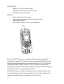
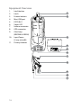
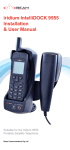
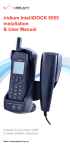
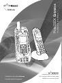
Installation & User Manual PotsDOCK Extreme PRESS 2 ABC 3 DEF 4 GHI 5 JKL 6 MNO 7PQRS 8 TUV * 0 [+ 1 9 WXYZ # aA me PotsD OCK Extre www.beamcommunications.com Suitable for the Iridium Extreme Portable Satellite Telephone 2011 Designed and manufactured by BEAM Communications Pty Ltd BEAM PotsDOCK Extreme Installation and User Manual Product name: PotsDOCK Extreme Manual revision: 04 Part Number: USRMAN007305 Release date: March 2013 BEAM Communications Pty Ltd 8 Anzed Court, Mulgrave, Victoria, 3170, AUSTRALIA Information furnished by BEAM Communications Pty Ltd is believed to be accurate and reliable. However, no responsibility is assumed by BEAM for its use, or for any infringement of patents or other rights of third parties, which may result from its use. No license is granted by implication or otherwise under any patent or patent rights of BEAM. BEAM reserves the right to change specifications at any time without notice. Copyright © 2011 BEAM Communications Pty Ltd. All rights reserved User Information Please record your serial number here for future reference: Model: EXTRMPD Serial no.: PD7 This number can be copied from the white label on the PotsDOCK Extreme Eg. PD700001 2 BEAM Communications BEAM Communications, a wholly owned subsidiary of World Reach Limited (WRR), listed on the Australian Stock Exchange, is a world leader in design, manufacture and distribution of specialized communications equipment for the Iridium Satellite Network. BEAM’s commitment to be at the forefront has continued to increase its share of the global satellite communications market. Its premium distribution network spans the world. Recognized as a leading provider of satellite communication solutions, BEAM specializes in Voice, Data, Tracking and customized solutions. BEAM develops innovative products and services to meet market demands and niche applications. BEAM’s leading edge products are deployed in a wide range of markets including Maritime, Transport, Government, Defence, Mining, Construction, Forestry, Emergency Services, Relief Aid, Telemetry and Rural Telephony. Supported by a dedicated team of professionals, BEAM has developed solid relationships with its peers and network of distributors worldwide. BEAM Communications Pty Ltd 8 Anzed Court, Mulgrave, Victoria, 3170, AUSTRALIA Web: www.beamcommunications.com Info: [email protected] Support: [email protected] Tel: +61 3 8588 4500 Fax: +61 3 9560 9055 3 Contents BEAM Communications 3 Conventions in this Manual 5 Terminology 6 Package Contents 7 Safety Information 9 About this equipment 14 Installation Guidelines 18 PotsDOCK Extreme Usage 31 Data Communications 50 Assuring Quality of Iridium Service 55 Specification Summary 57 Trouble Shooting 61 BEAM Warranty Conditions 63 4 Conventions in this Manual Warnings, cautions and notes appear throughout this manual and are represented by following conventions. WARNING / CAUTION: This symbol and associated text indicate a warning note providing information to prevent damage to equipment or personal injury. NOTE / IMPORTANT / TIP: This symbol and associated text indicate a note providing general operating information. INTERFERENCE: All wireless phones may get interference, which could affect performance RECORD: Write details of your unit for easy reference when required. Ideal when troubleshooting. 5 Terminology TERM DESCRIPTION Eagle Extreme Docks Configuration Tool - MS Windows Install GPS Global Positioning System HF Hands-free DPL Digital Peripheral Line SMS Short Message Service SBD Short Burst Data Mobile Originating Describes a call initiated by the PotsDOCK Extreme Mobile Terminating Describes an incoming call being answered by the PotsDOCK Extreme Extreme The Iridium Extreme Satellite Telephone ® The ® symbol, mark and logos are owned by the respective companies of which the symbol follows. Any use of such marks by BEAM Communications is under license. Other trademarks and trade names are those of their respective owners. RF Radio Frequencies AT Attention command, modem command set used for transceiver operation SMA SubMiniature version A co-axial RF connection 6 Package Contents Check that your PotsDOCK Extreme package contains: 1 x PotsDOCK Extreme Docking Cradle 1 x AC/DC Power Adaptor 1 x DC Power Cable/Fuse Kit 1 x RAM Mount 3 x M4 Screws and washers Quick Start Guide User Manual Optional Accessories The following optional accessories are available for your PotsDOCK Extreme • BEAM Privacy Handset Kit (RST755) • WHIP Antenna (RST714) • Magnetic Antenna (RST715) • Bolt Mount Antenna (RST720) • Active Antenna (RST740) • Dual Mode Mast Antenna (RST702) • Dual Mode Whip Antenna (RST706) • Man Down Kit (RST410) • UPS Battery Pack (RST055A) • Cable kits See your service provider for pricing and availability of the above quality BEAM accessories. 7 Additional Information For the latest in supporting software and documentation for PotsDOCK Extreme please visit: www.beamcommunications.com/support Data To use data on the PotsDOCK Extreme, the specific BEAM USB driver must be downloaded from the above link and installed on the PC connected to the PotsDOCK. Alert Loop To configure the alert loop (remote distress button) functionality on your PotsDOCK Extreme, you must first install the Eagle Configuration Tool software, which also includes the specific BEAM USB drivers. Other resources available online • Advanced Configuration – inbuilt to Eagle • Quick Start Guide & Manual • Iridium Direct Internet • Antenna Installation Guide • AT Command Set • Iridium Extreme Firmware Upgrade if required 8 Safety Information IMPORTANT! Please read the following information carefully before installing and using the BEAM PotsDOCK Extreme. Failing to follow instructions may compromise the safety of the product and may result in personal injury and/or equipment damage. Please consult your supplier if you have any further questions. WARNING: DO NOT open equipment. There are no user-serviceable parts inside. If a DC power supply is to be used, its output must comply with the Safety Extra Low Voltage (SELV) requirements of IEC60950. All connectors must only be connected to equipment ports which comply with the Safety Extra Low Voltage (SELV) requirements of IEC60950. 9 WARNING: POTENTIALLY EXPLOSIVE ATMOSPHERES • Turn your phone OFF and DO NOT remove your battery or remove the Extreme handset from the cradle when you are in any area with a potentially explosive atmosphere. • Obey all signs and instructions. • Sparks from your battery in such areas could cause an explosion or fire resulting in bodily injury or even death. • Areas with a potentially explosive atmosphere are often but not always clearly marked. They include, but are not limited to: »» fuelling areas such as gasoline stations »» below deck on boats; »» fuel or chemical transfer or storage facilities; »» areas where fuel odors are present (for example, if a gas/ propane leak occurs in a car or home); »» areas where the air contains chemicals or particles, such as grain, dust, or metal powders; »» any other area where you normally would be advised to turn off your vehicle engine. Safety – Iridium Transceiver Extreme Your Extreme handset is a low power radio transmitter and receiver. When it is ON, it receives and also sends out radio frequency (RF) signals. (NOTE: Refer to Iridium Extreme Phone Manual for additional Information) • The Iridium Extreme handset has a transceiver which is designed to be used with an external antenna. This antenna transmits RF energy. The Iridium antenna (fitted via an extension coaxial cable to the cradle) must be located more than > 0.3 meters (1 foot) from human body (person) when in operation. • International agencies have set standards and recommendations for the protection of public exposure to RF electromagnetic energy. ◊ International Commission on Non-Ionizing Radiation ◊ Protection (ICNIRP) 1996 ◊ Verband Deutscher Elektrotechniker (VDE) DIN-0848 ◊ United States Federal Commission, Radio Frequency Exposure Guidelines (1996) 10 ◊ National Radiological Protection Board of the United Kingdom, GS 11, 1988 ◊ American National Standards Institute (ANSI) IEEE. C95. 1-1992 These standards are based on extensive scientific review by scientists, engineers, and physicians from universities, government health agencies, and industry groups. They review the available body of research to develop ANSI standard. These ANSI standards are reviewed regularly for research development. • Do not operate your satellite telephone when a person is within 1 foot (30 centimeters) of the antenna. A person or object within 1 foot (30 centimeters) of the antenna could impair call quality and may cause the phone to operate at a higher power level than necessary and expose that person to RF energy in excess of that established by the international standards detailed above. • As a precaution, please maintain the maximum body distance possible from the antenna during call transmission. IMPORTANT! Cellular & Satellite terminals or mobiles operate using radio signals and communication networks. Because of this, the connection cannot be guaranteed at all times or under all conditions. Therefore, you should never rely solely upon any wireless device for essential communications, for example emergency calls. 11 Electronic Devices Most modern electronic equipment is shielded from RF signals. Certain equipment may not be shielded against the RF signals from your phone. Pacemakers The Health Industry Manufacturers Association recommends that a minimum separation of six inches (6”) be maintained between a wireless phone’s antenna and a pacemaker to avoid potential interference with the pacemaker. These recommendations are consistent with the independent research by and recommendations of Wireless Technology Research. Persons with pacemakers: • Should ALWAYS keep the phone more than six inches from their pacemaker when phone is turned ON • Should not carry the phone in a breast pocket. • Should use the ear opposite the pacemaker to minimize the potential for interference. • Should turn the phone OFF immediately if there is any reason to suspect interference is taking place Other Medical Devices If you use any other personal medical device, consult the manufacturer of your device to determine if it is adequately shielded from external RF energy. Your physician may be able to assist you in obtaining this information. Turn your phone OFF in health care facilities when any regulations posted in these areas instruct you to do so. Hospitals or health care facilities may be using equipment that could be sensitive to external RF energy. Posted Facilities Turn your phone OFF in any facility where posted notices require such as hospitals and on-board aircraft. 12 About this equipment PotsDOCK Extreme Key Features PotsDOCK Extreme CRADLE • Securely holds Iridium Extreme handset • Robust design and construction • Charges Iridium Extreme handset ready for use • Integrated antenna connection, Iridium & GPS • Integrated USB connectivity POTS/RJ11 • Supports standard cordless & corded telephones (5 REN) • POTS phone can be run 600m (2000 ft) from unit • Easily integrated to PBX system • Ring, busy & dial tones • Superior voice quality • Call number processing & quick dial TRACKING • Triggering of Quick GPS • Interfaces to Iridium’s LBS portal PANIC/ALERTS • Option of additional wired alert buttons • Interfaces to Iridium’s LBS portal • Supports Extreme SOS INTEGRATED BLUETOOTH® • Bluetooth® in-built in cradle • Supports Bluetooth® voice connectivity IN-BUILT RINGER • In-built ringer for enhanced ring indication VOICE, DATA, SMS, SBD • Supports all Iridium voice, data, SMS & SBD services • Access to prepaid, post paid & crew calling PRIVACY HANDSET (Optional) • Supports optional BEAM privacy handset • Auto answer when taken out of cup 13 INSTALLATION • Supports 9 - 32V DC power input • Flexible installation via universal mount • 100-240V AC pack included QUALITY • Professional industrial design • 2 year replacement guarantee for peace of mind • 100% factory tested • Full certified, Iridium, RoHS, CE, AS/EN60950 PRESS 2 ABC 3 DEF 4 GHI 5 JKL 6 MNO 7PQRS 8 TUV * 0 [+ 1 9 WXYZ # aA e PotsDO CK Extrem Beam PotsDOCK Extreme is a compact docking station specifically designed to support RJ11, Bluetooth and tracking. PotsDOCK allows the Iridium Extreme handset to be connected with an RJ11/POTS interface enabling standard corded, cordless or DECT handset connection or alternatively interfaced with a PBX system presenting standard ring, busy and dial tones like a standard phone network. PotsDOCK Extreme provides extra features such as Bluetooth for voice connectivity along with tracking and alert which can be configured to support periodic polling or emergency alert reporting. 14 Tracking / Alert Monitoring The PotsDOCK Extreme utilizes the Iridium Extreme’s tracking and emergency notification functions. The Track button is enabled (factory default setting). The Alert Loop (wires to an emergency distress button) is disabled, and requires Eagle Configuration Tool to enable it. Tracking When the Track button is pressed it initiates a Quick GPS message in the Iridium Extreme handset. The Track button can be enabled or disabled by holding the track button for 5 seconds. the Track button is enabled when Track LED is solid GREEN. Pressing the Track button (when enabled) then initiates a command for the Iridium Extreme Handset to send a Quick GPS message. Please ensure that the Quick GPS settings in the handset are correct before using this feature. Alert The PotsDOCK Extreme will trigger the emergency SOS function of the Iridium Extreme handset when there is a break (OPEN) in the alert loop wires. Please ensure that the SOS settings in the handset are correct before using this feature. 15 Equipment Overview 1. 2. 3. 4. 5. 6. 7. 8. 9. 10. 11. Latch button Latch Feature buttons Mini-USB port POTS/RJ11 Status LED Iridium connector GPS connector Alert loop (BROWN & GREEN) Input Power (4-way microfit) Privacy Handset 1 PRESS 2 3 PotsDOCK Extreme 4 5 6 SAT 7 8 N GREEN BROW 9 10 11 16 Installation Guidelines This guide outlines the process for installing the BEAM PotsDOCK Extreme in conjunction with an Iridium Extreme portable handset. This kit must only be used with the Iridium Extreme handset. • Only qualified personnel should install communication equipment. If necessary, contact the vehicle manufacturer for air bag information specific to the vehicle. • Ensure that the Dock is protected from dirt and moisture. • Select an area to mount components that do not interfere with driver or passengers seating or leg space. • Mount all components securely to prevent shifting that could cause injury or could interfere with safe vehicle operation. Always use the supplied mounting hardware. • Leave space around the units to allow airflow and ensure there are adequate clearance for cables. • Ensure the handset can be easily reached for normal operation. Routing Cables (for vehicle installations) • • • • Route cables so they are protected from pinching, sharp edges, and crushing. Use grommets wherever a cable must pass through a hole in a metal panel Keep all in-line connectors accessible. For an extra clean installation, a hole may be driven through the surface directly behind the docking station. 17 Guidelines for Electrical Connections The system is designed to operate in negative ground 9 to 32 Volt DC electrical systems only. IF using the DC cable: • The best power connection point for the positive primary power wire (RED) is the positive terminal of the vessel battery. Often, direct connection to the battery is inconvenient, and you may find it easier to connect the positive wire to the starter solenoid. Always select a point as close as possible to the battery. • Connect the (BLACK) negative power wire to a good ground point at the battery. If you must attach the negative primary power wire directly to the negative pole of the battery, you may optionally insert a 10-amp fuse (not included) into the ground (0V) line. Failure to insert a fuse can cause equipment to overheat IF a wiring fault exists. • Many parts of a vessel can produce electrical noise that interferes with the electrical radio system operation. The ignition system is the most common source of electrical noise interference. Before you begin installation, ensure that the ignition wiring and connections to the vehicle battery are in good working condition. • Verify that low resistance connections are present between the battery negative terminal, the vehicle chassis, and the engine block. All wire connections should be clean and tight. At 13.6 volts, the PotsDOCK Extreme cradle draws a maximum of 2Amp current. Please ensure that the vessel battery and alternator have sufficient current capacity to deliver at least 1 amp more than the maximum current that may be required by the vessel and its other accessories. WARNING: POTENTIALLY EXPLOSIVE ATMOSPHERES Do not connect the PotsDOCK interface power cable to power the unit until the full installation is completed. 18 Installation Procedure Installing the PotsDOCK Extreme Cradle Install the components in the following order. More detailed instructions can be found in the sections following. 1. Mount the PotsDOCK Extreme cradle 2. a) Install the external Iridium Antenna Connection and/or b) Install the GPS Antenna Connection (optional) 3. Connecting the RJ11/POTS Telephone (optional) 4. Install the external alert button (optional) 5. Connect the privacy handset (ordered as extra option) 6. Connect the DC power cable to the PotsDOCK Extreme 7. Configure Bluetooth® (optional) 8. Configure Tracking / Alert (optional) When selecting a location for the PotsDOCK Extreme, consider these guidelines: • Ensure the mounting surface is strong enough to support the cradle. • Allow enough room so that you can easily insert the Extreme handset into and remove it from the cradle. • Ensure that the PotsDOCK Extreme is within cable distance of power and antenna connections • Position the handset and cables so that it does not interfere with the vehicles operation or the occupants (driver or passenger) leg space or seating position. • Ensure sufficient room is allowed for the antenna and interface cables to be routed from the rear of the PotsDOCK Extreme. 19 Step 1 - Mounting the PotsDOCK Extreme cradle The PotsDOCK Extreme is supplied with a universal RAM® mount bracket that enables mounting to any flat surface (vertical or horizontal) within a vehicle, attached on a wall or on a table as required. 1. Attach one pivot base to the rear of the PotsDOCK Extreme using the M4 screws and washers supplied. 2. Secure the second pivot base to the location you have selected for mounting the PotsDOCK Extreme. (screws shown not supplied) 3. Use the interconnecting arm of the RAM® mount to secure the PotsDOCK Extreme to the pivot base and tighten into the desired location firmly using the wing nut on the arm. 20 Step 2a - Install the external Iridium Antenna Connection The external antenna connection can be found at the rear of the dock on the cable loom. Install the Iridium antenna in an appropriate location that has a clear sky view. Connect the RF cable between the antenna and the TNC female connector at the rear of the PotsDOCK Extreme. T SA WARNING: DO NOT pull with force on the cables from the rear of the PotsDOCK Extreme. Install strain relief clamping for the antenna cables where required to prevent damage to the PotsDOCK Extreme. Correct installation of the antenna is a vital part of the PotsDOCK Extreme system, to ensure reliable functionality, and drop-free calls. Use only quality low-loss antenna cabling, and ensure that the cable(s) and connectors to the antenna provide no more than 3dB attenuation (at frequency of 1.6GHz). WARNING: Do not place the antenna anywhere there is a source of heat or fumes such as the ship’s exhaust. NOTE:Refer to the section “Assuring Quality of Iridium Service” for more information on antenna placement and installation. 21 Step 2b - Install the GPS Antenna Connection (optional) GPS connection is required for Tracking and Emergency messaging. The GPS connection is optional if the Tracking and Emergency function are not required. If connected, and tracking is enabled, position or location information will be shown on your tracking messages and alert messages. The GPS connection provides a 3.3V source if an active GPS antenna is used. Install the GPS antenna in the appropriate location and then connect it to the SMA female connector on the antenna cable coming from the rear of the PotsDOCK Extreme. 22 Step 3 - Connect the RJ11/POTS Telephone (optional) Any standard analogue POTS Telephone (POTS = Plain Old Telephone Service) is supported by the PotsDOCK. It supplies power to the analogue phone as well as Ring, Dial and Busy tones. 1. Route the telephone cabling (up to 600m) from the PotsDOCK. 2. Mount the analogue phone if required, and plug the RJ11 cable into the PotsDOCK RJ11 port. The RJ11 port uses the middle 2 pins of the RJ socket, which is standard for analogue telephone cables. Step 4 - Install the external alert button (optional) PotsDOCK Extreme provides an additional cable pair (BROWN & GREEN wires) from its rear cable loom, known as the BEAM alarm loop. This provides a wire loop, when connected to any passive type of Normally CLOSED button, relay, or reed switch in which the action breaks the loop (OPEN) to activate the alarm state. The wires are 1.5 meters long but can be extended up to 50 meters. The alarm loop can support multiple alarm buttons/switches but they must be wired in SERIES. In this configuration, pressing any one of the buttons will OPEN the loop and activate the alarm and send the SOS message. To properly register the alarm state, the loop needs to be OPEN for at least 2 seconds (ie. holding down the button for 2 seconds activates the alarm). WN GREEN BRO 23 Step 5 - Connect Privacy Handset (Optional–Extra Order) The PotsDOCK Extreme provides a 4-pole 3.5mm audio socket at the bottom of the Dock, for connection to the BEAM Privacy Handset. This provides a local handset function, conveniently mounted next to the PotsDOCK Extreme cradle. 1. The Privacy Handset Kit (purchased/ordered separately) contains a handset cup, a mounting bracket, space plate, screws, washers and nut bolts. 2. Attach the handset cup to the mounting plate in the desired left or right orientation. 3. 4. Place the spacer into the circular cavity in the rear of the Dock. Using the longer (M4x20) screws provided in the kit, secure the mounting plate between the Dock and the RAM base. The shortest (M4x8) screw to secure to the back of the Dock and the 3 x M4x12 screws to secure the cup with the washer and nut bolt behind the bracket. a b + 5. c + d + e + = Plug the Privacy Handset 4-pole connector into the audio socket on the rear cable loom. Privacy Handset mode is enabled when the handset is removed from the cup. Please ensure to re-dock the Privacy Handset when not in use. 24 Step 6 - Connect the DC power cable to the PotsDOCK Extreme Once all the components are installed, apply power to the PotsDOCK via the 4-way Microfit connector using the AC/DC power adaptor or the DC power cable. A: Power from the AC/DC Adaptor If the PotsDOCK is used inside a building where mains power is available, it can be powered from the AC/DC power adaptor. The supplied AC/DC power adaptor supports international AC voltage ranges for global compatibility. Please follow the steps below to connect the power. 1. Ensure that the power adaptor cable has enough length to reach the PotsDOCK cradle and it is plugged into a power outlet of suitable safe power capability. If using a power-board extension, please ensure that it is not overloaded. 2. Connect the 4-way output connector from the power adaptor to the matching 4-way connector from the rear cable loom of the PotsDOCK cradle as shown below. Please note that while the PotsDOCK is powered by the AC/DC adaptor, it will always be turned ON unless power is removed. B: Power from the DC Power Cable Power is supplied to the PotsDOCK Extreme via the 4-way Microfit® connector using the DC power cable. The DC power cable has three wires, RED, BLACK and YELLOW. The RED and BLACK wires are used for the power connection. The YELLOW wire can be connected to a vehicle’s accessories, ignition or other similar circuits to control the ON/OFF status of the PotsDOCK Extreme in synchronization with a vehicles operation. 25 By default, the PotsDOCK Extreme will stay on for 20 minutes after this input is switched off and if a call is in progress while this occurs, the PotsDOCK Extreme will stay on for 20 minutes after the call is terminated. Please follow the steps below to connect the DC power cable to the vehicle battery power and the PotsDOCK Extreme. 1. Place, but do not connect, the 4-way Microfit connector on the DC power cable beside the 4-way power connector on the rear cable loom of the PotsDOCK Extreme. 2. Route the other end of the DC power cable to the connection point. DO NOT apply power until the following steps are completed. 3. Connect the black wire to the negative terminal of the battery or the vehicle chassis (if negatively grounded chassis). 4. Connect the RED wire to the positive terminal of the battery. It is recommended to add a 3A fuse (supplied) between them. 5. 6. RED (+) Vin 9 to 32VDC BLACK (-) OV Power Ground YELLOW (IGN) Ignition / Accessory To Battery Positive Terminal (3A Fuse recommended) To Negative Terminal or chassis To ACC switched power (1A Fuse recommended) Connect the YELLOW wire to the vehicle accessory power. If the accessory power is unavailable, this may be connected to a vehicle ignition voltage. It is recommended to add a 1A (supplied) fuse between them. The accessory wire enables the PotsDOCK Extreme to turn on and off as the vehicle key is enabled or disabled. If this function is not required, the YELLOW wire MUST be connected to the RED wire. Once all the components have been installed, connect the 4-way Microfit connector to the PotsDOCK Extreme and the DOCK on. Wiring for a Marine Application When installed in a marine application using the DC power cable, the YELLOW wire can be wired to a suitable panel switch which will allow the PotsDOCK Extreme to be turned off when not in use. 26 Step 7 - Bluetooth® Configuration (Optional) PotsDOCK has an in-built Bluetooth® module for voice connectivity. NOTE: In this manual, when there is a reference to the Bluetooth® button or the Bluetooth® LED it is referring to the button shown below located on the front of the PotsDOCK Extreme. To configure/pair to a Bluetooth® headset (audio) device: 1. Power up the PotsDOCK Extreme cradle. 2. Press and hold the Bluetooth® button on the cradle for 5 seconds, until the cradle sounds a double (2) beep. The Bluetooth® LED will then flash blue and orange. 3. Hold the headset (device) button(s) to enter the pairing mode (please refer to the headset user manual). 4. Once the devices are successfully paired, the Bluetooth® LED on the cradle will change to solid blue. 5. Bluetooth® can be turned ON with a single press, and OFF by pressing and holding the Bluetooth® button for 2 seconds on the cradle. The cradle will sound a single (1) beep when turning off. Once paired, the PotsDOCK Extreme will automatically connect to this device every time the PotsDOCK Extreme powers up. You may repeat this process to pair more than one headset. Ensure only one device is switched on during subsequent pairing configuration. To clear (delete) all the registered devices from the cradle settings, press and hold the Bluetooth button (10 seconds) until 3 beeps are heard. NOTE: Once a Bluetooth device is discovered, the PotsDOCK will attempt to pair to that device by trying each of the password “0000”, “1234”, and then the optional password set in the Eagle. 27 Step 8 - Tracking & Alert Configuration (optional) Tracking & Alert requires the installation of a GPS antenna, and setup of the tracking and/or alerting messages. Please refer to the Eagle software to enable and configure Tracking & Alert. Please refer to the Iridium Extreme Handset User Manual to configure the tracking and emergency alert operation and destinations. NOTE: If the BEAM alarm loop is to be used, remember to enable the external loop in the Eagle settings. Once enabled, the loop will be armed and activated with an open-loop condition. To avoid false triggering, be sure to have the normally closed button wired into the alert loop, before applying power. Initiate a Quick GPS tracking message When the TRACK button of the PotsDOCK is pressed, the Extreme Handset will attempt to send a Quick GPS message (according to the settings of the Extreme Handset) Refer to Track Button/LED operation for further information. Emergency alerting mode If the Alert loop is configured in Eagle, the PotsDOCK will trigger the emergency (SOS) function of the Extreme Handset. This triggering is activated by a user breaking the alarm loop connected to the dock. The Alert can also be activated by pressing the SOS button on the Extreme Handset itself. 28 PotsDOCK Extreme Usage Extended Iridium Extreme Battery Iridium provide an optional extra high capacity battery that can replace the standard battery. To accommodate the larger battery, a Battery Infill must be removed from the Dock. 2 Cents Ten C Ten en ts ts Ten Ce en Cents Ten C sT en nt Ten Ce en Cents Ten C sT en nt s Cents Ten C en Ten t ts Removal 2. Place a fingernail/coin/ screwdriver in the slot and push the infill towards the centre of Dock. 1 Ten Cen ts 1. Ten Cen ts Insertion a) Locate the Battery Infill in the base of the Dock b) slide the Infill into the right side of the Docking area till it ‘Clicks’ into place a b “CLICK” 29 Docking your Extreme handset 1. At the base of the Iridium Extreme handset there is an accessory connector cover. Open the cover and move it to the back of the handset, securing it to the two rear retaining features. 2. Press down the latch button and then gently rotate it up to open the latch, then place the Iridium Extreme handset into the PotsDOCK Extreme 3. Lift the latch back over the handset or until it Click’s into place 30 “CLICK” Removing the Iridium Extreme 1. To remove the handset, first press down on the latch button and then rotate the latch up and away from the handset. The handset can now be slid up and out of the PotsDOCK. Refit the accessory connector cover to maintain the IP rating of the Iridium Extreme handset. 31 Check Before Use To ensure the best operation of the phone and Dock, upgrade to the latest firmware revisions in both products Upgrade Firmware 1. Ensure that the PotsDOCK Extreme is running with the latest firmware which can be located at: www.beamcommunications.com/support/potsdockextreme 2. Ensure that the Iridium Extreme Handset is running with the required compatible firmware which can be located at: www.beamcommunications.com/support/potsdockextreme Operation of the PotsDOCK Extreme Starting Up 1. Retract the antenna into the Extreme handset. 2. Place the Extreme handset into the PotsDOCK Extreme as per instructions “Docking & Undocking” on page 30 & 31. 3. If using the yellow accessory input wire, switch the vehicle ignition to ACC or ON position. The PotsDOCK Extreme will automatically power up followed by a single beep. The Extreme handset will then start to initialise. The PotsDOCK Extreme will sound a rising double (2) beep. 4. Wait for the Extreme handset to register on the Iridium network. 5. Wait for the Status LED on the Dock to be solid GREEN. 6. You are now ready to make and receive calls. 32 NOTE: The Extreme handset can be removed whilst powered, however the handset will turn off automatically. If it is removed during a call, the Extreme Handset will attempt to remain in call as long as antenna is extended and in sky view. The call may drop out during this transition, and the phone may turn off. NOTE: If the Extreme handset fails to connect with the cradle, the cradle will power cycle the Extreme Handset twice when it is docked and after that, it will power down the Extreme Handset and put it into a one-minute Charge Only Mode with ALL SIX LEDs will flash ORANGE slowly, but one column (2 LEDs) at a time. After the one minute, the cradle will try again to connect with the Extreme Handset. If it still fails, the cradle will follow the above sequence however for a 10-minute duration of Charge Only Mode. One common cause for connection failure is a flat Extreme battery which prevents the Extreme Handset, from being turned on in the cradle. The one-minute and ten-minute charge cycle will ‘resurrect’ the battery and once the Extreme Handset is connected with the cradle, charging will resume on the Extreme Handset. If the Extreme handset is removed from the cradle during the charging process, then reinserted, the startup process will restart from the beginning. Please be patient during this startup sequence. ALL SIX LEDs will flash ORANGE slowly, but one column (2 LEDs) at a time - during above charging process. 33 Charging the Iridium Extreme Handset The PotsDOCK Extreme provides charging power to the Extreme handset via its accessory connector. The Extreme Handset battery is a lithium-ion cell which has a safety temperature range whilst charging. This range is from 0°C - 45°C (32°F - 113°F). Due to the increased heating effects on the Extreme handset whilst it is docked and being charged, it is ideal for the ambient temperature to be approximately 10 degrees below the 45 degree upper limit for the handset to charge the battery whilst docked. If the battery temperature exceeds this limit, then the Extreme may cease charging until the temperature is reduced. NOTE: Please allow for tolerance variation of the cutoff temperature in the Iridium battery. Ensure the Dock solution is the best choice (versus a fixed transceiver) for the installation, so that a compatible charging environment is available. 34 RJ11 POTS Phone Use Mobile Originating 1. Lift the RJ11/POTS phone handset “OFFHOOK” and listen for the dial tone. 2. Dial (using the full country codes) on the RJ11 telephone keypad. 3. A message will display on the Iridium Extreme handset to indicate the call is progressing. 4. Once the call is connected, the STATUS LED will flash to indicate a call is in progress. 5. Place the RJ11/POTS phone handset “ON HOOK” to terminate the call. Mobile Terminating 1. The RJ11/POTS phone will sound its ringer. 2. Lift the RJ11/POTS phone handset “OFFHOOK” to answer the call. NOTE: When the privacy handset is used to originate or answer a call, the RJ11/POTS interface will be disabled. Therefore if you un-hook the connected POTS phone while the privacy handset is in use, you will hear an unavailable tone. However, you can still transfer the audio to a connected Bluetooth® headset by pressing the Bluetooth® button. NOTE: The PotsDOCK internal ringer will also sound during an incoming call. This can be changed by a single press of the Ringer button, whilst out of call. (Please refer to the section “Ringer Selection” for more details on pg.38) 35 Bluetooth® Phone Call - Mobile Originating A Bluetooth® call can be started by using the Extreme Handset keypad. 1. Ensure that the Bluetooth® audio headset is connected with the PotsDOCK Extreme, i.e. the Bluetooth® LED is turned on in blue. 2. Dial the phone number (using the full country code) on the Extreme Handset keypad or press the Call button on the Bluetooth® headset which will then dial the last called number. A call progress message will appear on the Extreme Handset display and the audio is automatically routed to the Bluetooth® headset. During the call, the Bluetooth® LED will flash slowly in blue. 3. Press the red key on the Extreme handset to terminate the call. Options: A. During a call, you may transfer the audio to the optional Privacy handset by removing it out of its cup. This automatically directs the call audio to the Privacy handset. To return the call back to the Bluetooth® headset, put the Privacy handset back in its cup. Bluetooth® Phone Call – Mobile Terminating A Bluetooth® call can be started by using the Extreme keypad. 1. Ensure that the Bluetooth® audio headset is connected with the PotsDOCK Extreme, i.e. the Bluetooth® LED is turned on in blue. 2. Answer the incoming call by either one of the bellow: • Pressing the Bluetooth® headset answer button • Pressing the green key on the Extreme keypad. 3. To end the call by either one of the bellow: • Pressing the Bluetooth® headset answer button • Pressing the red key on the Extreme keypad. Once the call is in progress, Option A from “A Bluetooth® Phone Call – Mobile Originating” is also applicable. 36 Privacy Handset Use NOTE: In this manual, when there is a reference to the Ring button or the Ring LED it is referring to the button shown below located on the front of the PotsDOCK Extreme Privacy handset Phone Call - Mobile Originating 1. Remove the Privacy handset from its cup 2. Dial the phone number (using the full country code) on the Extreme keypad whilst docked. Press the green button 3. A beep sound should be heard from the handset and a message is displayed on the Extreme to indicate a call is in progress. 4. Once the call is connected, the Ring LED will flash in orange to indicate the Privacy handset is in use. 5. Press the red key on the Extreme handset to terminate the call. Privacy Handset Phone Call - Mobile Terminating 1. Answer an incoming call by taking the Privacy handset off the cup. 2. Press the red key on the Extreme handset to terminate the call. NOTE: Returning the Privacy handset to the cup does NOT hang up the call. 37 Mute Mode NOTE: The Mute function only operates DURING a call. Once the call is ended, Mute mode is exited. In this manual, when there is a reference to the Mute button or the Mute LED it is referring to the button shown below located on the front of the PotsDOCK Extreme Mute functionality The mute function of the PotsDOCK Extreme allows the user to mute either the Handsfree Microphone, Bluetooth®, or privacy handset audio in the uplink direction (To Satellite, from Dock). 1. During a call, Press the Mute button on the face of the PotsDOCK Extreme, a RED LED will illuminate the Mute button to confirm that the PotsDOCK Extreme is muted. 2. To exit the Mute mode, press the mute button once. Ringer Selection The PotsDOCK Extreme has an internal ringer that sounds during an incoming call. The ring tones can be changed by a press of the Ringer button, when OUT of call. A preview of the sound will be heard after each press, and the setting is stored. 38 Tracking & Alert Operations NOTE: In this manual, when there is a reference to the Track button or the Track LED it is referring to the button shown below located on the front of the PotsDOCK Extreme Enable Tracking & Alert The Tracking button is enabled by default. The Alert function is not active by default and it has to be enabled using the Eagle software via the miniUSB connection to the PotsDOCK Extreme. Please refer to the Eagle User Guide for more details on how to configure and enable the Tracking & Alert functions on the PotsDOCK Extreme. The destination options of Tracking (Quick GPS message) and Alert messages is managed by the Iridium Extreme handset. Send Tracking Position In order to send a tracking message, the following conditions must be fulfilled. 1. Tracking LED is solid GREEN (Track button is enabled). 2. The Quick GPS feature must be configured in the Extreme handset. 3. The Iridium Extreme handset is registered with the Iridium network. 4. The Iridium Extreme handset, has acquired enough satellite signals and navigational data to calculate a GPS fix. To manually send a tracking message of the current location 1. Apply a single press to the Track button. The Track LED will flash green for 5 seconds. A beep will sound (if configured to do so in the Eagle). 2. The Track LED will stop flashing after 5 seconds. 39 Activate Alert Mode Alert mode can be activated by one of the following two methods: 1. Pressing the SOS button on the top of the Iridium Extreme handset. 2. If the alert loop is broken (OPEN) . This feature must be enabled in the Eagle application. Once triggered into the Alert mode, the Track LED flashes Red for 10 seconds. The internal buzzer will beep 3 times (intervals: 3sec on 1sec off) at the loudest volume. Once triggered, a countdown will appear on the screen of the Iridium Extreme. The user will have 20sec to press the right soft key labelled CANCEL to stop the Emergency Mode if initiated accidently. To trigger a second alarm, the alarm loop needs to be reconnected and then broken again. NOTE: The Alert Loop (externally wired distress button) MUST be configured in the Eagle before use. This is disabled by default. NOTE: Please refer to the Iridium Extreme User Manual for configuration of the Track and Alert message format, destinations, and intervals. 40 Sleep mode The PotsDOCK can enter a low-power SLEEP mode after pre-defined waiting time (20 minutes by default) when a Extreme Handset is docked AND its accessory input is turned OFF (and is not set to be “ignored” in the Eagle application). If the accessory/ignition input is SET to be ignored, then the PotsDOCK will always stay in the RUN mode. Accessing the yellow accessory on/off wire requires using the DC cable (instead of using the AC/ DC Adaptor) If a call is in progress, the waiting time will start after the call is terminated. When the waiting time is over and if there is a Extreme Handset in the dock which is ON, the PotsDOCK will produce disconnection tones from its internal ringer and turn off the Extreme Handset. Please note that the PotsDOCK will enter the SLEEP mode straight away if there is no Extreme Handset docked. The PotsDOCK will return to the RUN mode when one of the following wake up events is enabled and occurs. 1. 2. 3. Ignition ON Alert loop is disconnected Connecting to a USB host via the mini-USB port In SLEEP mode, most of the PotsDOCK circuits will be turned off and it should consume about 25mA current. However, it is possible that the charging power source is ON for the Extreme Handset while the PotsDOCK is put into SLEEP mode. In this case, the total current consumption will be 25mA plus the extra current required by the Extreme Handset charging. 41 PotsDOCK Extreme Front Panel LOCATION BUTTON MODE ACTION LED/SOUND Mute press On/off In a Call: Mute the microphone (uplink) on the Bluetooth Hands-free or optional privacy handset LED turns RED Muted LED turns OFF Not muted Up/Down In a Call: Increase/decrease volume on the audio device in use Audio will sound louder/quieter with each press. Out of Call or Incoming Ring: Increase/decrease volume of incoming ring tone on the internal speaker. (The lowest setting will silence the Ringer) A beep will sound indicating the increased/ decreased ring tone volume of the internal speaker OR Brightness Mode: Increase/decrease the LED intensity + Brightness dual button simultaneous press (2 seconds) Out of Call: Enter LED brightness change mode. Then Press UP and/or DOWN arrows to vary intensity. Mode will automatically exit after 5 seconds after the last button press. 42 All Button LEDs will be increased/ decreased with each press. Status LED flashes YELLOW 3 times and all Button LED’s will change WHITE. A single beep will sound when entering brightness change mode. A short double beep will sound when exiting change mode. LOCATION BUTTON MODE ACTION Ringer Single Press Not in Call: Cycle through the ring tones of the internal buzzer. The last Ringer type sounded is then saved. Single Press (no beep sound) When Bluetooth is OFF: Turns ON Bluetooth function If Bluetooth connected but NOT used in Call: Transfer the audio to the Bluetooth device LED/SOUND Ring tone playback and the output device changes. LED FLASHING (Fast) BLUE when Ring Tone is sounded. LED changes from OFF to FAST FLASHING in BLUE when searching Bluetooth device(s). LED turns solid BLUE when connected LED changes from Solid BLUE to SLOW FLASHING in BLUE Bluetooth Device being Used in Call: Transfer the audio to Privacy handset if activated LED changes from Slow Flashing to solid BLUE Single Press 1.5 sec (until 1 beep sounds) Bluetooth function is ON: Turns OFF Bluetooth function LED turns OFF Single Press 5 sec (until 2 beep sounds) Bluetooth function is ON: Bluetooth is set to discovery mode for pairing to Bluetooth devices Single Press 10 sec (until 3 beep sound) Bluetooth is ON or OFF: Clear all paired Bluetooth devices and turn off Bluetooth function LED is FAST FLASHING ORANGE and BLUE, and then turns solid BLUE when paired and connected. LED turns OFF 43 LOCATION BUTTON MODE ACTION Single Press (until 1 beep sounds) In Tracking Mode*: Send a tracking message to the pre-configured destination in the Extreme Handset Single Press 5 sec (until 2 beeps sound) Enables / Disables Track button LED/SOUND LED flashes GREEN for 5 seconds. A beep will sound to indicate that a tracking message is to be sent# LED Solid GREEN is enabled, LED OFF is disabled * This action is optional, and only when tracking for your Extreme Handset is configured and activated. Using the Track button only initiates the command to send a Quick GPS message - check that the Extreme Handset is configured correctly. # A beep will only sound if audible alerts are enabled in Eagle 44 Button LED Reference GREEN RED BLUE ORANGE N/A Mic / Uplink audio Mute N/A N/A GREEN RED BLUE ORANGE FLASHING (slow) Incoming call ringing N/A N/A Privacy Handset or RJ11 POTS Phone is in use FLASHING (fast) N/A N/A Ring Tone Playback N/A ILLUMINATED BLUE ORANGE ILLUMINATED Connected with a paired BT device. Ready for accepting incoming call or switch to an active call N/A FLASHING (fast) Searching a paired BT device N/A FLASHING (slow) BT device is being used in a call N/A ALTERNATING Bluetooth in Discovery Mode Blue Orange Bluetooth in Discovery Mode Blue Orange NOTE: Bluetooth LED will turn OFF if there are no paired devices OR BLUE ORANGE FLASHING (slow) N/A Error Mode (Check Error log codes in Eagle) ALL BUTTONS BLUE ORANGE N/A Charge Only Mode – all LEDs flash (2 at a time) FLASHING (slow) 45 Status LED ILLUMINATED FLASHING (slow) GREEN RED YELLOW Ready to receive or place a call (registered) - No Iridium signal - Not registered - No SIM card - Firmware Upgrade Mode (in conjunction with all other LED’s illuminated red) - DTR present on data port - LED brightness adjustment mode N/A - Data Call in progress (DCD active) - Enter/Exit LED brightness adjustment mode Voice Call in progress ALTERNATING (Slow) RED YELLOW DPL communication, or PCM Clock problem YELLOW GREEN Short-circuit on “Alert Loop” output or “Horn alert / Audio system mute” output RED YELLOW GREEN System Error (see Log in Eagle). The Arrow buttons will also flash ORANGE in this state. 46 Data Communications The PotsDOCK Extreme provides the convenience of accessing Iridium data services via the mini-USB connector located on the bottom of the cradle while the Extreme handset is docked. You should consult your service provider for full details on the availability of this service with your account. Data communication with the Extreme handset provides the following: • Ability to issue AT commands directly to the Extreme • Undertake Circuit Switched Data (CSD), Short Burst Data (SBD) and Short Message Service (SMS) communication when services are provisioned. • Access the internet via Iridium Direct Internet 3 or through a Dial-Up connection NOTE: Learn more about Data Services available at: www.beamcommunications.com Using the USB Data Port When the Extreme handset is docked in the PotsDOCK Extreme cradle, its USB data function is available through the mini-USB connector, on the bottom of the PotsDOCK Extreme. For more information on using the Extreme handset’s USB port, please refer to the Extreme handset user manual. The Iridium Extreme adaptor must be removed prior to insertion in the Dock. 47 To connect a PC/laptop to the PotsDOCK Extreme bottom mini-USB port, you will require a mini-USB-B to USB-A data cable. This cable is included in your original Extreme package. USB Driver Installation The PotsDOCK Extreme USB data port requires an interface driver to be installed on the user’s computer prior to undertaking data communication. This driver supports the following operating systems: Windows XP (SP3 or above) & Windows Vista, 7 You can download the Windows driver for the PotsDOCK Extreme from http://www.beamcommunications.com/support/potsdockextreme Please note that Iridium only supplies Direct Internet 3 software for the Microsoft Windows-based operating system. After the driver is successfully installed, two new serial ports should appear in the Ports (COM & LPT) section of the Windows Device Manager as shown below. Please use the USB Data port for data communication. The USB Application port is used for PotsDOCK Extreme configuration via the Eagle. 48 AT Commands When utilizing the USB data communication port, the PotsDOCK Extreme cannot activate AT commands that could interrupt the docking station’s synchronization with the Extreme handset. Therefore, the PotsDOCK Extreme will block or limit AT commands that could cause any adverse effects to the functional operation of the cradle. Please refer to the Iridium “ISU AT Command Reference” document for more details on the AT commands supported by Iridium. www.beamcommunications.com/support/potsdockextreme The document is located under Common Resources then “Iridium AT command guide.” The following AT commands are affected: AT COMMAND AT+IPR CRADLE DEFAULT STATUS 6,0 LIMITATION Auto-baud is permanently disabled with the default baud rate set to 19200. ATEn 1 Echo is on permanently enabled ATVn 0 Numerical responses only AT&Cn 0 DCD is forced on at all times ATQ1 1 ISU responses are not sent to the DTE AT&F0 - Blocked AT&W1 - Blocked AT&Yn - Blocked 49 Iridium Extreme Display Definitions Display Status indicators and Icons The following icons will appear in your Extreme handset display to provide you with various information about the phone’s activity. Main Screen Components 1. Battery Strength 2. Indicates an SMS message has been received 3. Indicates a voicemail has been received 4. Indicates the keypad is locked 5. Indicates SOS button and Emergency Mode has been activated 6. Signal Strength 7. Network/SIM status 8. Date 9. Real Time 10. Left and right soft key functions Menu Components 11. Menu Title 12. Black bar scrolls up and down when using the 2-way nevi-key 13. Menu Options 14. Arrow indicates to scroll up or down for additional options 15. Left and right soft key functions 1 2 3 4 5 6 7 Registered 8 9 15:40 Menu 09-JUL-11 Help 10 11 12 13 14 Phonebook Call SMS Edit Delete New Memory Status Notes Select 15 50 sos Back Power-On Messages Once your phone is powered on, you may see: MESSAGE MESSAGE DESCRIPTION Bad Card See Supplier. Your SIM car has been damaged or incorrectly issued. Contact your service provider for information. Check Card The SIM card is damaged or inserted the wrong way. Denied Your phone has seen a network, but has been denied access. SIM PIN Enter the four-to eight- digit SIM card PIN code provided by your service provider and press OK to proceed. See”Using the Security Menu” in the Iridium Extreme manual for more information about your SIM. Invalid Account Contact your service provider. Phone PIN The phone has been locked. To unlock the phone, you must enter the correct Phone PIN number. PIN Blocked When the PIN number has been entered incorrectly three times in a row, the phone automatically blocks the PIN. To unblock the PIN, enter the PUK1 code for the phone by entering **05* from the main screen. PIN 2 Blocked When the PIN2 number has been entered incorrectly three times in a row, the phone automatically blocks the PIN. To unblock the PIN2 enter the PUK2 code for the phone by entering **052* from the main screen. Registered Your phone is now registered with the network. Searching for network... The phone is attempting to establish communications with the satellite network. This message appears while your phone searches for a network connection. CAUTION! Emergency call recipient has not been configured. Refer to user guide and edit Emergency Actions is set to Message and Call or Call Only and a Call Recipient has not been configured. See the Iridium Extreme manual for more details. CAUTION! Emergency SMS recipient has not been configured. Refer to user guide and edit Emergency Actions is set to Message and Call or Message Only and SMS Contact has not been configured. See the Iridium Extreme manual for more details. Press Edit to configure the Emergency Call Recipient or Cancel to proceed to the main window. Press Edit to configure the Message Recipient or Cancel to proceed to the main window. 51 Assuring Quality of Iridium Service Iridium is committed to providing subscribers around the world with consistent, reliable, quality voice and data access all day, every day. The Iridium satellite system is monitored for call performance from numerous locations 24 hours a day, 7 days a week in order to achieve this. There are conditions that can compromise the quality of the service you may receive. These include: • Obstructions • Cabling • RF Interference Obstructions The antenna must be able to “see” the entire sky from approximately 8 degrees above the horizon. Nearby tall buildings or similar structures, heavily leafed trees and mountains can all degrade performance as they block the signal between the antenna and the satellites. Having a completely open view of the sky plays a very important role in maximising performance, as the Iridium satellites cross the sky from North horizon to South horizon during a connected call. All surrounding obstructions must be lower than the top of a fist extended at arms length and the bottom of the fist placed on the horizon. Iridium performance is immune from natural environments such as clouds, fog, rain, snow, wind and smoke. l Visibility Ful 8° 52 Cabling Using an externally mounted antenna provides an ideal solution for many applications. It is very important that both the antenna cabling and antenna are BEAM approved products. Always ensure all RF connectors are screwed together firmly and ensure there are no sharp bends in the cabling between the PotsDOCK Extreme and the antenna. RF Interference All wireless devices, including satellite telephones, are susceptible to RF (radio frequency) interference from other electronic devices. This problem is more evident when numerous antennas and broadcasting devices are located within close proximity to each other. Symptoms of RF Interference Symptoms of RF interference often resemble those that arise when an Iridium phone is being operated with an obstructed view of the sky. Some of these symptoms include; erratic or no signal strength indication dropped calls or warbled or otherwise distorted voice. These symptoms may be intermittent or persistent, depending largely on the interference source, its distance, strength and frequency relative to the Iridium unit. Mitigation of RF Interference Iridium Service degradation due to RF interference can be significantly improved by: Increasing the distance and moving the Iridium antenna off axis from the source of the interference. 53 Specification Summary Electrical & Environmental Specifications POWER SPECIFICATIONS Rated Input 9-32V DC, 2A max AC Power Pack 100-250V AC 50-60Hz, Output15V DC 60W Average Power Consumption Current @ 15V Power Watts Standby 75mA 1.1W Transmit + Charging 0.4A 6W Sleep Mode 25mA 0.3W INTERFACES RJ11/POTS RJ11 connector / 2-wire, up to 600m. Auto Impedance - or country selectable. Adjustable Dial & Busy Tones. Ringer output 56Vrms, 5REN load. Adjustable Ringer Frequency / Cadence. Privacy Handset (Line In/Out) 4-pole 3.5mm jack, ground referenced in/out with cup-switch. In biased with ~2Vdc via 2k2. Out 40mW power into 16-32Ω. Data Port (USB) USB mini-B 5-pin female (USB Slave). USB 2.0 compliant, CDC serial profile. Alarm (Alert) Loop 1 input, 1 output Alarm Mode: “Normally-Closed” Loop IN to OUT Up to 50m cable run/ multiple buttons in series. Brown wire is Input, Green wire is Output. Power Cable 4-way microfit socket. +Vin, 0V (GND), and ACC (On/ Off Sense). 9-32VDC tolerant. ACC sense: High(1) > +7Vdc and < +32Vdc Low (0) 0V < +5Vdc BLUETOOTH® MODULE (INTERNAL) System Bluetooth® 2.0v+EDR (Enhanced Data Rates), 802.11 coexistence. Profiles HFP - Hands-Free Profile v.1.5 HFP-AG - Hands-Free Audio Gateway Profile v.1.5 & SPP - Serial Port Profile Power Default = Class 2 (< 10 metres). 2.4GHz - 2.4835GHz Unlicensed ISM Band 54 Antenna Integrated chip antenna Regulatory Bluetooth® identifier: B03005. CE 89/336/EEC - #EC/2006/20013C. FCC part 15 class B: PotsDOCK contains Transmitter Module FCC ID: QOQWT11. Canada: Cert# 5123A-BGTWT11E Japan:07215089/AA/00 Legal The Bluetooth® word, mark and logos are owned by the Bluetooth® SIG, Inc. and any use of such marks by Beam Communications is under license. Other trademarks and trade names are those of their respective owners. ENVIRONMENTAL Operate Temp. Range* PotsDOCK -20°C to +70°C Extreme Handset -10°C to +55°C Charging Temp. Range# 0°C to 45°C Operating Humidity Range < 85% RH non-condensing Storage Temperature -30°C to +85°C Weight Cradle 0.45kg (1.0 lbs) EMC Compliance EN301489-1/-20 RoHS Full compliant RoHS Directive EU 2002/95/EC (All 6 substances) WEEE For EU countries, this product must be collected separately from household waste, as defined in each region. This product must not be discarded together with household waste. Flame Retardant UL94.0 Safety - SELV AS/NZ 60950-1 * When Extreme Battery is fully charged # Derived from the charging temperature range of the Iridium Extreme handset battery. This is the temperature that the battery reaches whilst charging, which is always warmer than the air temperature. Also allow for tolerance variation of the cutoff temperature in the Iridium battery. 55 Cradle Dimensions 212.0 26.4 82.8 PotsDOCK Extreme Dimensions in millimeters 75.9 56 167.6 212.0 26.4 PotsDOCK Extreme Dimensions in millimeters with optional Privacy Handset attached 77.9 57 Trouble Shooting This chapter provides information to help you troubleshoot problems you may encounter while running the PotsDOCK. Q1 The Extreme handset is docked into the PotsDOCK, but the Extreme handset is not turned on and the PotsDOCK doesn’t seem to have power. A Press the Ring button and you should hear a tone. (if volume buttons are at low Silent mode) If not, the PotsDOCK is either not being powered up or is in the SLEEP mode. Make sure the Extreme is docked correctly. Refer to the section “Docking & Undocking Extreme Handset” for more details. Disconnect the power cable and check if there is voltage on the power cable. Make sure that the power cable is connected properly to the 4-way Microfit connector on the PotsDOCK cable loom. It is possible to plug the power cable into the Microfit connector in the wrong way by force. If applicable, check the position of the vehicle ignition or accessory output. It should be in the ON position. Otherwise, the PotsDOCK may be in the SLEEP mode. Q2 The Extreme handset is docked into the PotsDOCK, but it fails to register with the Iridium network. A Check the Iridium antenna connector on the cable loom is properly connected to the external antenna. Check the external antenna is installed properly with clear sky view. Refer to the “Assuring Quality of Iridium Service” section for more details. Check if there is a valid SIM card in the Extreme handset. Remove the Extreme handset from the PotsDOCK and test it on its own. Make sure the Extreme is docked correctly. Refer to the section “Docking & Undocking Extreme Handset” for more details. Q3 The Extreme handset in the PotsDOCK keeps re-booting about every 20 minutes. A Please check if the Extreme handset is registered with the Iridium network. If the PotsDOCK detects that the Extreme handset is not registered with the network, it will try to re-boot the Extreme handset every 20 minutes by default. Refer to the question 2 to fix the registration issue. Q4 The Extreme handset is docked into the PotsDOCK. It keeps being turned on and off by the PotsDOCK then eventually turns off and stays off. All LEDs flash orange slowly (3 LEDs at a time). A This is generally caused by a very flat Extreme battery or bad contacts between the Extreme bottom connector and the PotsDOCK base connector. It indicates that the PotsDOCK has trouble communicating with the Extreme handset. Please try the following methods to recovery. The PotsDOCK is actually in the CHARGE only mode charging the Extreme handset battery. If this is caused by a flat battery, the PotsDOCK will automatically recover in either 1 minute or 10 minutes. If the battery is not flat, please remove the Extreme handset from the PotsDOCK and clean its bottom connector. Also check the PotsDOCK base connector and make sure there are no damaged pins on this connector. Re-dock the Extreme into the PotsDOCK. 58 Q5 The Extreme handset is inserted into the PotsDOCK. The battery indicator on the Extreme handset does not show that the battery is being charged. A There are a number of reasons which could stop the Extreme battery charging. When the Extreme handset is inserted into the PotsDOCK, please wait for about 100 seconds for the charging to start. If the Extreme battery is full, the Extreme handset will stop the PotsDOCK charging the battery. If the temperature of the Extreme battery has exceeded 45ºC, the Extreme handset will stop the PotsDOCK charging the battery. For this reason, if the ambient temperature is close to 45ºC, no charging will occur due to the safety requirement for charging Lithium-Ion type battery. Q6 The Extreme handset is docked in the PotsDOCK and seems to turn off about 20 minutes after the vehicle’s ignition is switched off OR the key is removed. A This is normal for PotsDOCK. If the PotsDOCK needs to stay on while the ignition is off, please wire the yellow accessory input on the PotsDOCK cable loom to a constant power source in the vehicle, e.g. 12/24VDC. Q7 A call is established using the privacy handset but the other end (party B) cannot hear my voice. A Check if the Mute LED is illustrating red. If so, the mute function is enabled. Press the Mute button once to disable the mute. Check if the Bluetooth® LED is flashing blue at 1.5 second on and 1.5 second off rate. If so, the PotsDOCK is currently connected to a previously paired Bluetooth® device. Press the Bluetooth® button on the PotsDOCK until a beep sounds to turn off the Bluetooth®. Q8 If my SIM card has a pin code, do I need to manually unlock the SIM card every time I dock my Extreme handset into the PotsDOCK? A The user can save their SIM pin code into the PotsDOCK via the Eagle application. Once saved, the PotsDOCK will automatically enter the pin code while the Extreme is inserted into the Dock. Status LED Error Codes ALTERNATING (Slow Flashing) RED YELLOW DPL communication, or PCM Clock problem YELLOW GREEN Short-circuit on “Alert Loop” output or “Horn alert / Audio system mute” output RED System Error (see Log in Eagle). The Arrow buttons will also flash YELLOW ORANGE in this state. GREEN For additional product support contact BEAM: Web: www.beamcommunications.com Info: [email protected] | Support: [email protected] Tel: +61 3 8588 4500 | Fax: +61 3 9560 9055 59 BEAM Warranty Conditions BEAM Communications gives this express warranty (along with extended warranty endorsements, where applicable) in lieu of all other warranties, express or implied, including (without limitation), warranties of merchantability and fitness for a particular purpose. This constitutes our sole warranty and obligation with regard to our products as well as the Customer’s sole remedy. BEAM Communications expressly disclaims all liability and responsibility for any special, indirect or consequential damages or any further loss of any kind whatsoever resulting from the use of our product(s). The Customer’s sole and exclusive remedy and the limit of BEAM liability for any loss whatsoever, shall not exceed the purchase price paid by the Customer for the product to which a claim is made. All products manufactured by BEAM Communications are warranted to be free from defects in material and workmanship in accordance with and subject to the following terms and conditions: 1. This warranty is limited to the original Customer only. It cannot be transferred or assigned to third parties unless the intent to transfer to a third party is expressly indicated in a purchase order and/ or warranty-processing arrangements have been agreed upon in writing by BEAM. 2. BEAM Communications does not warrant any installation, maintenance or service of the Products not performed by BEAM, nor does it warrant the use of Products with unapproved ancillary products. 3. BEAM Communications will correct any defects in material or workmanship of products manufactured by BEAM which appear within (12) months and (24) months replacement warranty for Docking Stations ONLY, from the date of shipment by BEAM Communications to the Customer. BEAM Communications will repair or replace, at our option, any defective product,provided that our analysis and/or inspection discloses that such defects developed under normal and proper use. 4. This warranty does not extend to goods subjected to liquid or particulate ingress, extreme humidity, misuse, neglect, accident or improper installation, or to maintenance or repair of products that have been altered or repaired by anyone except BEAM Communications unless otherwise stated in writing. 5. The warranty is a return-to-base warranty and freight is paid by the sender. 6. A charge of USD $150 including return freight will be made for testing returned product which is not defective or is found to be defective as the result of improper use, maintenance or neglect. 7. BEAM Communications will not accept responsibility for any invoiced goods or services that are not covered by a BEAM Communications written purchase order. Under no circumstances does BEAM Communications agree to pay for labour or other related expenses associated with the troubleshooting and/or repair of our product without prior specific written authorization. 8. Information in our descriptive literature is based on product specifications that are current at the time of publication. Product specifications, designs and descriptive literature are subject to change as improvements are introduced. Although we announce changes as they occur, we cannot guarantee notification to every Customer. BEAM Communications warrants delivered product to conform to the most current specifications, designs and descriptive literature. 9. This warranty policy may be expanded or limited, for particular categories of products or Customers, by information sheets published as deemed appropriate by BEAM Communications. The warranty for third party Products is that of the third party and not BEAM warranty. 60 NOTES NOTES BEAM COMMUNICATIONS GLOBAL HEAD OFFICE ph | +61 3 8588 4500 fax | +61 3 9560 9055 AMERICAS tel | +1 954 376 5062 EUROPE tel | +44 208 144 1405 fax | +44 208 289 3542 Sales | [email protected] General | [email protected] Support | [email protected] www.beamcommunications.com AFRICA | ASIA | AUSTRALIA | EUROPE | MIDDLE EAST | NORTH AMERICA | SOUTH AMERICA