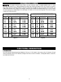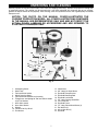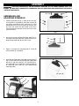
1
Sharpening Center
(Model 23-710)
PART NO. 1346949 - 05-14-04
Copyright © 2004 Delta Machinery
To learn more about DELTA MACHINERY
visit our website at: www.deltamachinery.com.
For Parts, Service, Warranty or other Assistance,
please call
RTD10000127AA
1-800-223-7278 (In Canada call 1-800-463-3582).
INSTRUCTION MANUAL
62079
SAFETY GUIDELINES - DEFINITIONS
This manual contains information that is important for you to know and understand. This information relates to protecting YOUR SAFETY and PREVENTING EQUIPMENT PROBLEMS. To help you recognize this information, we use the
symbols below. Please read the manual and pay attention to these sections.
Indicates an imminently hazardous situation which, if not avoided, will result in death or serious injury.
Indicates a potentially hazardous situation which, if not avoided, could result in death or serious injury.
Indicates a potentially hazardous situation which, if not avoided, may result in minor or moderate injury.
Used without the safety alert symbol indicates potentially hazardous situation which, if not avoided, may
result in property damage.
SOME DUST CREATED BY POWER SANDING, SAWING, GRINDING, DRILLING, AND OTHER
CONSTRUCTION ACTIVITIES contains chemicals known to cause cancer, birth defects or other reproductive harm.
Some examples of these chemicals are:
· lead from lead-based paints,
· crystalline silica from bricks and cement and other masonry products, and
· arsenic and chromium from chemically-treated lumber.
Your risk from these exposures varies, depending on how often you do this type of work. To reduce your exposure to
these chemicals: work in a well ventilated area, and work with approved safety equipment, always wear MSHA/NIOSH
approved, properly fitting face mask or respirator when using such tools.
GENERAL SAFETY RULES
READ AND UNDERSTAND ALL WARNINGS AND OPERATING INSTRUCTIONS BEFORE
USING THIS EQUIPMENT. Failure to follow all instructions listed below, may result in electric shock,
fire, and/or serious personal injury or property damage.
IMPORTANT SAFETY INSTRUCTIONS
Woodworking can be dangerous if safe and proper operating procedures are not followed. As with all machinery, there
are certain hazards involved with the operation of the product. Using the machine with respect and caution will
considerably lessen the possibility of personal injury. However, if normal safety precautions are overlooked or ignored,
personal injury to the operator may result. Safety equipment such as guards, push sticks, hold-downs, featherboards,
goggles, dust masks and hearing protection can reduce your potential for injury. But even the best guard won’t make
up for poor judgment, carelessness or inattention. Always use common sense and exercise caution in the workshop.
If a procedure feels dangerous, don’t try it. Figure out an alternative procedure that feels safer. REMEMBER: Your
personal safety is your responsibility. For additional information please visit our website www.deltamachinery.com.
This machine was designed for certain applications only. Delta Machinery strongly recommends that this
machine not be modified and/or used for any application other than that for which it was designed. If you have any
questions relative to a particular application, DO NOT use the machine until you have first contacted Delta to determine
if it can or should be performed on the product.
Technical Service Manager
Delta Machinery
4825 Highway 45 North
Jackson, TN 38305
(IN CANADA: 505 SOUTHGATE DRIVE, GUELPH, ONTARIO N1H 6M7)
2
GENERAL SAFETY RULES
FAILURE TO FOLLOW THESE RULES MAY RESULT IN SERIOUS INJURY.
1. FOR YOUR OWN SAFETY, READ THE INSTRUCTION
MANUAL BEFORE OPERATING THE MACHINE.
Learning the machine’s application, limitations, and
specific hazards will greatly minimize the possibility of
accidents and injury.
2. WEAR EYE PROTECTION. ALWAYS USE SAFETY
GLASSES. Also use face or dust mask if cutting
operation is dusty. Everyday eyeglasses are NOT safety
glasses. USE CERTIFIED SAFETY EQUIPMENT. Eye
protection equipment should comply with ANSI Z87.1
standards, hearing equipment should comply with
ANSI S3.19 standards, and dust mask protection
should comply with MSHA/NIOSH certified respirator
standards. Splinters, air-borne debris, and dust can
cause irritation, injury, and/or illness.
3. WEAR PROPER APPAREL. Do not wear loose
clothing, gloves, neckties, rings, bracelets, or other
jewelry which may get caught in moving parts. Nonslip
footwear is recommended. Wear protective hair
covering to contain long hair.
4. DO NOT USE THE MACHINE IN A DANGEROUS
ENVIRONMENT. The use of power tools in damp or
wet locations or in rain can cause shock or
electrocution. Keep your work area well-lit to prevent
tripping or placing arms, hands, and fingers in danger.
5. MAINTAIN ALL TOOLS AND MACHINES IN PEAK
CONDITION. Keep tools sharp and clean for best and safest
performance. Follow instructions for lubricating and changing
accessories. Poorly maintained tools and machines can further
damage the tool or machine and/or cause injury.
6. CHECK FOR DAMAGED PARTS. Before using the
machine, check for any damaged parts. Check for
alignment of moving parts, binding of moving parts,
breakage of parts, and any other conditions that may
affect its operation. A guard or any other part that is
damaged should be properly repaired or replaced.
Damaged parts can cause further damage to the
machine and/or injury.
7. KEEP THE WORK AREA CLEAN. Cluttered areas and
benches invite accidents.
8. KEEP CHILDREN AND VISITORS AWAY. Your shop is a
potentially dangerous environment. Children and visitors can
be injured.
9. REDUCE THE RISK OF UNINTENTIONAL STARTING.
Make sure that the switch is in the “OFF” position
before plugging in the power cord. In the event of a
power failure, move the switch to the “OFF” position.
An accidental start-up can cause injury.
10. USE THE GUARDS. Check to see that all guards are in
place, secured, and working correctly to prevent injury.
11. REMOVE ADJUSTING KEYS AND WRENCHES
BEFORE STARTING THE MACHINE. Tools, scrap
pieces, and other debris can be thrown at high speed,
causing injury.
12. USE THE RIGHT MACHINE. Don’t force a machine or
an attachment to do a job for which it was not
13.
14.
15.
16.
17.
18.
19.
20.
21.
22.
23.
24.
3
designed. Damage to the machine and/or injury may
result.
USE RECOMMENDED ACCESSORIES. The use of
accessories and attachments not recommended by
Delta may cause damage to the machine or injury to
the user.
USE THE PROPER EXTENSION CORD. Make sure
your extension cord is in good condition. When using
an extension cord, be sure to use one heavy enough
to carry the current your product will draw. An
undersized cord will cause a drop in line voltage,
resulting in loss of power and overheating. See the
Extension Cord Chart for the correct size depending
on the cord length and nameplate ampere rating. If in
doubt, use the next heavier gauge. The smaller the
gauge number, the heavier the cord.
SECURE THE WORKPIECE. Use clamps or a vise to
hold the workpiece when practical. Loss of control of
a workpiece can cause injury.
FEED THE WORKPIECE AGAINST THE DIRECTION OF
THE ROTATION OF THE BLADE, CUTTER, OR
ABRASIVE SURFACE. Feeding it from the other
direction will cause the workpiece to be thrown out at
high speed.
DON’T FORCE THE WORKPIECE ON THE MACHINE.
Damage to the machine and/or injury may result.
DON’T OVERREACH. Loss of balance can make you
fall into a working machine, causing injury.
NEVER STAND ON THE MACHINE. Injury could occur if
the tool tips, or if you accidentally contact the cutting tool.
NEVER
LEAVE
THE
MACHINE
RUNNING
UNATTENDED. TURN THE POWER OFF. Don’t leave the
machine until it comes to a complete stop. A child or visitor
could be injured.
TURN THE MACHINE “OFF”, AND DISCONNECT THE
MACHINE FROM THE POWER SOURCE before
installing or removing accessories, before adjusting
or changing set-ups, or when making repairs. An
accidental start-up can cause injury.
MAKE YOUR WORKSHOP CHILDPROOF WITH
PADLOCKS, MASTER SWITCHES, OR BY
REMOVING STARTER KEYS. The accidental startup of a machine by a child or visitor could cause
injury.
STAY ALERT, WATCH WHAT YOU ARE DOING,
AND USE COMMON SENSE. DO NOT USE THE
MACHINE WHEN YOU ARE TIRED OR UNDER
THE INFLUENCE OF DRUGS, ALCOHOL, OR
MEDICATION. A moment of inattention while
operating power tools may result in injury.
TAKE PRECAUTIONS
AGAINST
DUST
INHALATION. The dust generated by certain woods
and wood products can be injurious to your health.
Always operate machinery in well-ventilated areas,
and provide for proper dust removal. Use wood dust
collection systems whenever possible.
ADDITIONAL SAFETY RULES FOR SHARPENING CENTERS
FAILURE TO FOLLOW THESE RULES MAY RESULT IN SERIOUS INJURY.
1.
2.
3.
4.
5.
6.
7.
8.
9.
10.
11.
12.
13.
14.
15.
DO NOT OPERATE THIS MACHINE until it is
completely assembled and installed according to the
instructions. A machine incorrectly assembled can
cause serious injury.
OBTAIN ADVICE from your supervisor, instructor, or
another qualified person if you are not thoroughly
familiar with the operation of this machine. Knowledge
is safety.
FOLLOW ALL WIRING CODES and recommended
electrical connections to prevent shock or
electrocution.
ALWAYS USE THE PROVIDED BLOTTER AND
WHEEL FLANGES to mount the grinding wheels on
the grinder shaft to prevent wheel damge or accidental separation. Separation can result in fragments
flying off the wheel at high speeds.
USE ONLY WHEELS suitable for the speed of the
machine. Unsuitable grinding wheels can come apart,
throwing fragments out at high speeds.
USE ONLY WHEELS that have a bore exactly equal
to the arbors of the machine. Never attempt to
machine an undersized wheel to fit an arbor.
Unsuitable grinding wheels can come apart, throwing
fragments out at high speeds.
DO NOT OVERTIGHTEN WHEEL NUT.
DO NOT USE A WHEEL THAT VIBRATES. Dress the
grinding wheel, replace it, or replace the bearings of
the shaft. Unsuitable grinding wheels can come apart,
throwing fragments at high speeds.
INSPECT WHEELS before starting the machine for
cracks or fragments. REPLACE DAMAGED WHEELS
immediately. Parts of the wheel can be thrown at high
speeds causing serious injury.
ADJUST EYE SHIELDS close to the grinding wheel,
and re-adjust as the wheel wears down. Flying sparks
are dangerous and can cause fires or explosions.
ALWAYS MAKE SURE the eye shields are in place,
properly adjusted, and secured.
ADJUST TOOL RESTS close to the grinding wheel
(1/8" separation or less). Tighten the tool rest securely
to prevent shifting positions, and re-adjust as the
wheel wears down. The workpiece can be drawn into
the wheel, causing damage to the workpiece and/or
serious injury.
STAND TO ONE SIDE before turning the machine
“ON”. Loose fragments or wheel parts could fly from
the wheel at high speeds.
NEVER GRIND ON A COLD WHEEL. Run the grinder
for one full minute before applying the workpiece. A
cold wheel has a tendency to chip. Those fragments
could fly from the wheel at high speeds.
NEVER START THE MACHINE with the workpiece
against the grinding wheel. The workpiece can be
drawn into the wheel, causing damage to the machine
16.
17.
18.
19.
20.
21.
22.
23.
24.
25.
26.
27.
28.
and/or serious injury.
CLEAN THE MACHINE thoroughly when processing
different types of workpieces (wood, steel, or
aluminum). Combining wood and metal dust can
create an explosion or fire hazard. DO NOT GRIND
OR POLISH MAGNESIUM. Fire will result.
NEVER GRIND NEAR FLAMMABLE GAS OR
LIQUIDS. Sparks can create a fire or an explosion.
AVOID AWKWARD OPERATIONS AND HAND
POSITIONS. A sudden slip could cause a hand to
move into the grinding wheel.
KEEP ARMS, HANDS, AND FINGERS away from the
wheel. The abrasive surfaces can cause serious injury.
HOLD THE WORKPIECE FIRMLY against the tool
rest. Loss of control of the workpiece can cause
serious injury.
DRESS THE WHEEL on the face only. Dressing the
side of the wheel could cause it to become too thin
for safe use.
GRIND A WORKPIECE using the face of the grinding
wheel only. Loss of control of the workpiece can
cause serious injury.
NEVER APPLY COOLANT directly to the grinding
wheel. Coolant can weaken the bonding strength of
the grinding wheel and cause it to fail. Dip the
workpiece in water to cool it.
DO NOT TOUCH the ground portion of a workpiece
until it has cooled sufficiently. Grinding creates heat.
PROPERLY SUPPORT LONG OR WIDE WORKPIECES. Loss of control of the workpiece can cause
serious injury.
NEVER PERFORM LAYOUT, ASSEMBLY, or set-up
work on the table/work area when the machine is
running. A sudden slip could cause a hand to move
into the wheel. Severe injury can result.
TURN THE MACHINE “OFF”, disconnect the
machine from the power source, and clean the
table/work area before leaving the machine. LOCK
THE SWITCH IN THE “OFF” POSITION to prevent
unauthorized use. Someone else might accidentally
start the machine and cause serious injury to
themselves.
ADDITIONAL INFORMATION regarding the safe
and proper operation of power tools (i.e. a safety
video) is available from the Power Tool Institute, 1300
Sumner Avenue, Cleveland, OH 44115-2851
(www.powertoolinstitute.com). Information is also
available from the National Safety Council, 1121
Spring Lake Drive, Itasca, IL 60143-3201. Please
refer to the American National Standards Institute
ANSI 01.1 Safety Requirements for Woodworking
Machines and the U.S. Department of Labor OSHA
1910.213 Regulations.
SAVE THESE INSTRUCTIONS.
Refer to them often
and use them to instruct others.
4
POWER CONNECTIONS
A separate electrical circuit should be used for your machines. This circuit should not be less than #12 wire and should
be protected with a 20 Amp time lag fuse. If an extension cord is used, use only 3-wire extension cords which have 3prong grounding type plugs and matching receptacle which will accept the machine’s plug. Before connecting the
machine to the power line, make sure the switch (s) is in the “OFF” position and be sure that the electric current is of
the same characteristics as indicated on the machine. All line connections should make good contact. Running on low
voltage will damage the machine.
DO NOT EXPOSE THE MACHINE TO RAIN OR OPERATE THE MACHINE IN DAMP LOCATIONS.
MOTOR SPECIFICATIONS
Your machine is wired for 120 volts 60 HZ alternating current. Before connecting the machine to the power source,
make sure the switch is in the “OFF” position.
GROUNDING INSTRUCTIONS
THIS MACHINE MUST BE GROUNDED WHILE IN USE TO PROTECT THE OPERATOR FROM
ELECTRIC SHOCK.
1. All grounded, cord-connected machines:
2. Grounded, cord-connected machines intended for use
on a supply circuit having a nominal rating less than 150
volts:
In the event of a malfunction or breakdown, grounding
provides a path of least resistance for electric current to
reduce the risk of electric shock. This machine is
equipped with an electric cord having an equipmentgrounding conductor and a grounding plug. The plug must
be plugged into a matching outlet that is properly installed
and grounded in accordance with all local codes and
ordinances.
If the machine is intended for use on a circuit that has an
outlet that looks like the one illustrated in Fig. A, the
machine will have a grounding plug that looks like the plug
illustrated in Fig. A. A temporary adapter, which looks like
the adapter illustrated in Fig. B, may be used to connect
this plug to a matching 2-conductor receptacle as shown
in Fig. B if a properly grounded outlet is not available. The
temporary adapter should be used only until a properly
grounded outlet can be installed by a qualified electrician.
The green-colored rigid ear, lug, and the like, extending
from the adapter must be connected to a permanent
ground such as a properly grounded outlet box. Whenever
the adapter is used, it must be held in place with a metal
screw.
Do not modify the plug provided - if it will not fit the outlet,
have the proper outlet installed by a qualified electrician.
Improper connection of the equipment-grounding
conductor can result in risk of electric shock. The
conductor with insulation having an outer surface that is
green with or without yellow stripes is the equipmentgrounding conductor. If repair or replacement of the
electric cord or plug is necessary, do not connect the
equipment-grounding conductor to a live terminal.
NOTE: In Canada, the use of a temporary adapter is not
permitted by the Canadian Electric Code.
Check with a qualified electrician or service personnel if
t h e g ro u n d i n g i n s t r u c t i o n s a re n o t c o m p l e t e l y
understood, or if in doubt as to whether the machine is
properly grounded.
Use only 3-wire extension cords that have 3-prong
grounding type plugs and matching 3-conductor
receptacles that accept the machine’s plug, as shown in
Fig. A.
IN ALL CASES, MAKE CERTAIN
THE
R E C E P TA C L E I N Q U E S T I O N I S P R O P E R LY
G R O U N D E D . I F Y O U A R E N O T S U R E H AV E A
QUALIFIED ELECTRICIAN CHECK THE RECEPTACLE.
Repair or replace damaged or worn cord immediately.
GROUNDED OUTLET BOX
GROUNDED OUTLET BOX
GROUNDING
MEANS
CURRENT
CARRYING
PRONGS
ADAPTER
GROUNDING BLADE
IS LONGEST OF THE 3 BLADES
Fig. A
5
Fig. B
EXTENSION CORDS
Use proper extension cords. Make sure your extension cord is in good condition and is a 3-wire
extension cord which has a 3-prong grounding type plug and matching receptacle which will accept the machine’s
plug. When using an extension cord, be sure to use one heavy enough to carry the current of the machine. An
undersized cord will cause a drop in line voltage, resulting in loss of power and overheating. Fig. D-1 or D-2, shows
the correct gauge to use depending on the cord length. If in doubt, use the next heavier gauge. The smaller the gauge
number, the heavier the cord.
MINIMUM GAUGE EXTENSION CORD
MINIMUM GAUGE EXTENSION CORD
RECOMMENDED SIZES FOR USE WITH STATIONARY ELECTRIC MACHINES
RECOMMENDED SIZES FOR USE WITH STATIONARY ELECTRIC MACHINES
Ampere
Rating
Volts
Total Length
of Cord in Feet
Gauge of
Extension Cord
Ampere
Rating
Volts
Total Length
of Cord in Feet
Gauge of
Extension Cord
0-6
0-6
0-6
0-6
120
120
120
120
up to 25
25-50
50-100
100-150
18 AWG
16 AWG
16 AWG
14 AWG
0-6
0-6
0-6
0-6
240
240
240
240
up to 50
50-100
100-200
200-300
18 AWG
16 AWG
16 AWG
14 AWG
6-10
6-10
6-10
6-10
120
120
120
120
up to 25
25-50
50-100
100-150
18 AWG
16 AWG
14 AWG
12 AWG
6-10
6-10
6-10
6-10
240
240
240
240
up to 50
50-100
100-200
200-300
18 AWG
16 AWG
14 AWG
12 AWG
10-12
10-12
10-12
10-12
120
120
120
120
up to 25
25-50
50-100
100-150
16 AWG
16 AWG
14 AWG
12 AWG
10-12
10-12
10-12
10-12
240
240
240
240
up to 50
50-100
100-200
200-300
16 AWG
16 AWG
14 AWG
12 AWG
12-16
12-16
12-16
120
120
120
up to 25
25-50
14 AWG
12 AWG
12-16
12-16
12-16
240
240
240
up to 50
50-100
14 AWG
12 AWG
GREATER THAN 50 FEET NOT RECOMMENDED
GREATER THAN 100 FEET NOT RECOMMENDED
Fig. D-2
Fig. D-1
FUNCTIONAL DESCRIPTION
FOREWORD
The Delta Industrial Sharpening Center Model 23-710 has a 1/5 HP motor. It also comes with a 5” diameter, 120 grit
aluminum oxide dry wheel, an 8” diameter, 1000-grit wet wheel, a tool rest and base, a sliding tool holder, a water tank,
eye shield and wrenches.
6
UNPACKING AND CLEANING
Carefully unpack the machine and all loose items from the shipping container(s). Remove the protective coating from
all unpainted surfaces. This coating may be removed with a soft cloth moistened with kerosene (do not use acetone,
gasoline or lacquer thinner for this purpose). After cleaning, cover the unpainted surfaces with a good quality household
floor paste wax.
NOTICE: THE PHOTO ON THE MANUAL COVER ILLUSTRATES THE
CURRENT PRODUCTION MODEL. ALL OTHER ILLUSTRATIONS CONTAINED
IN THE MANUAL ARE REPRESENTATIVE ONLY AND MAY NOT DEPICT THE
ACTUAL COLOR, LABELING OR ACCESSORIES AND ARE INTENDED TO
ILLUSTRATE TECHNIQUE ONLY.
1
2
10
4
11 12 13
3
14
16
15
17
18
8
5
19
20
21
23
6
9
22
7
Fig. 2
1.
2.
3.
4.
5.
6.
7.
8.
9.
10.
11.
Sharpening Center
Water Tank
Tool and Chisel Holder
Wheel Dressing Stone
Tool and Chisel Holder Base Assembly
Tilting Screw and Spring for Tool and Chisel Holder
w/(2) Flat Washers
6mm Allen wrench
6mm Allen Wrench
Wrench
Tool Rest for Dry Wheel
Flat Washer
7
12.
13.
14.
15.
16.
17.
18.
19.
20.
21.
22.
23.
Lockwasher
5/8” Long Hex Head Screw
Eyeshield Clamp Bracket
Eyeshield Mounting Rod
Eyeshield Lock Knob
3/4” Long Carriage Head Bolt
1/4-20 Hex Nut
Eyeshield Frame
1/2” Long, Round Head Screw (2)
Flat Washer (2)
#10-24 Hex Nut (2)
Eyeshield
ASSEMBLY
FOR YOUR OWN SAFETY, DO NOT CONNECT MACHINE TO THE POWER SOURCE UNTIL THE
MACHINE IS COMPLETELY ASSEMBLED AND YOU HAVE READ AND UNDERSTAND THE ENTIRE
INSTRUCTION MANUAL.
C
C
ASSEMBLING AND
ADJUSTING EYESHIELD
B
1. Position eyeshield (A) Fig. 3, under lip of frame (B).
Line up holes in eyeshield (A) with holes in frame (B)
and fasten eyeshield to frame using two 1/2” long
round head screws (C), flat washers (D) and hex nuts
(E). Place flat washer on round head screw, place
screw through hole and then fasten hex nut to screw
under the frame.
D
D
E
E
A
Fig. 3
2. Insert short end of eyeshield mounting rod (F) Fig. 4,
into top of frame (B) and fasten in place with the 3/4”
long carriage head bolt (G) and hex nut (H).
F
G
H
B
3. Figure 5, illustrates the mounting rod (F), frame (B)
and eyeshield (A) assembled.
Fig. 4
B
4. Assemble the long end of eyeshield mounting rod (F)
Fig. 6, to the side of the dry wheel guard using clamp
bracket (J) and lock knob (K). The eyeshield (A) is
fully adjustable to any position by moving shield (A)
or loosening lock knob (K) and repositioning
mounting rod (F).
F
A
F
J
Fig. 5
K
A
Fig. 6
8
ASSEMBLING AND
ADJUSTING TOOL REST
FOR DRY WHEEL
B
1. Assemble dry wheel tool rest (A) Fig. 7, to mounting
arm (B) using flat washer (C), lockwasher (D) and
5/8” long hex head screw (E). Place a lockwasher
then a flat washer on the hex head screw, then
assemble tool rest to mounting arm as shown in Fig.
8.
A
C
D
E
Fig. 7
H
2. Figure 8, illustrates dry wheel tool rest (A) assembled
to mounting arm (B). Wrench (F) supplied, is used to
tighten screw (E).
A
3. The tool rest (A) Fig. 8, is adjustable so the inside
edge of the tool rest can be positioned as close to
the grinding wheel (H) as possible, giving maximum
support to the piece that is being ground. Always
maintain a distance of 1/8” or less between the
grinding wheel (H) and inside edge of tool rest (A). As
the grinding wheel wears down to a smaller
diameter, readjust the tool rest closer to the wheel by
loosening screw (E), moving tool rest (A) inward and
tightening screw (E) using wrench (F). The tool rest
(A) can also be rotated to any desired angle by
loosening screw (E), rotating tool rest (A) and
tightening screw. Rotate dry wheel (H) making
certain wheel does not contact tool rest (A).
B
F
E
Fig. 8
WRENCH HOLDING BRACKET
1. Wrench (D) Fig. 10, can be stored in bracket (A)
when not in use.
A
D
Fig. 10
9
ASSEMBLING AND ADJUSTING
TOOL AND CHISEL HOLDER
A
B
1. Take the tool and chisel holder base and insert its
mounting post (A) Fig. 11, into hole (B) in the front of
the machine, and tighten screw (C) against groove
(E) of mounting post. Use the provided wrench (D)
Fig. 10.
E
2. Loosen screw (C) Fig. 13, move tool and chisel
holder to desired position and tighten screw (C).
C
Fig. 11
3. Place flat washer, spring and another flat washer
onto the tilting screw knob. Thread tilting screw and
spring assembly (H) Fig. 13, into hole in post. NOTE:
End of screw (H) contacts lever (R) and this screw is
used to tilt the tool rest base (J).
H
J
G
R
4. To level tool and chisel holder base (J) Fig. 13, with
the set grinding wheel (G), loosen screw (F) with
supplied wrench, and turn complete base assembly
(E) until tool and chisel holder base (J) is level with
wet grinding wheel (G), and tighten screw (F).
E
C
F
A
Fig. 13
5. To adjust the height of tool and chisel holder base
assembly (E) Fig. 14, loosen screw (S) and turn adjustment knob (T). Tighten screw (S) after height
adjustment is made.
S
E
T
Fig. 14
10
6. Place tool and chisel holder (K) Fig. 15, in position on
base (J).
J
K
Fig. 15
7. Fig. 16, illustrates tool and chisel holder (K) in
position on tool rest base (J).
K
8. To raise or lower the tool and chisel holder assembly
(E) Fig. 17, refer to STEP 5.
9. To tilt the tool and chisel holder (J) Fig.17, to conform
with the angle of the tool to be sharpened, loosen set
screw (N) and turn knob (H) as necessary. After angle
is set, tighten set screw (N).
J
Fig. 16
10. To move the tool and chisel holder (J) Fig. 17, in or
out, loosen set screw (C), and slide assembly (E) in
or out as desired. After adjustment, tighten screw
(C).
N
J
H
11. To level tool and chisel holder base (J) Fig. 17, with
the wet grinding wheel (G), loosen screw (F) with
supplied wrench, and rotate complete base
assembly (E) until tool and chisel holder base (J) is
level with wet grinding wheel (G), and tighten screw
(F).
E
F
C
Fig. 17
ASSEMBLING AND ADJUSTING
WATER TANK
1. Insert stem (A) Fig. 18, of water tank (B) into holder
(C) as shown.
B
A
C
Fig. 18
11
G
2. The water tank (B) Fig. 19, can be rotated to direct
the water from the spigot (D) onto the grinding wheel.
The ideal position of the spigot (D) would be to the
center (C) of the grinding wheel.
E
D
3. To control the flow of water from the spigot (D) Fig.
19, turn knob (E).
B
Fig. 19
4. A drain (F) Fig. 20, is provided underneath the
grinding wheel housing to dispose of water. Place a
can or suitable container underneath the drain (F).
F
Fig. 20
FASTENING SHARPENING CENTER
TO SUPPORTING SURFACE
If during operation there is any tendency for the machine
to tip over, slide or "walk" on the supporting surface, the
machine must be secured to the supporting surface. Two
holes, (A) Fig. 9, are provided for this purpose.
A
A
Fig. 21
12
C
OPERATION
USING TOOL AND CHISEL HOLDER
The tool and chisel holder is supplied as standard equipment with your sharpening center and is ideal for sharpening wood chisels, plane irons, some lathe turning
tools, etc. To use the tool and chisel holder, proceed as
follows.
A
1. Loosen the two clamp knobs (A) Figs. 25, 26 and 27,
and insert the tool or chisel between the clamp as
shown, making sure the edge of the tool or chisel is
against the inside of the protractor gage (B). Fig. 25
illustrates a plane iron; Fig. 26 illustrates a wood
chisel; and Fig. 27 illustrates a lathe turning tool
inserted between the clamp of the tool and chisel
holder. Then tighten the two clamp knobs (A). Adjust
the protractor gage (B) so that the cutting edge of
the tool to be sharpened is the correct angle for the
grinding wheel. Loosen screw (C) Fig. 27, and adjust
the protractor gage (B) as shown. Tighten screw (C)
after angle is obtained.
B
Fig. 25
A
2. Place the complete tool and chisel holder assembly
(D) Fig. 28, on the tool rest base (E) as shown.
Adjustment of the tool rest is explained in section
“ASSEMBLING AND ADJUSTING TOOL AND
CHISEL HOLDER.”
B
Fig. 26
A
3. Figure 29, illustrates a plane iron being sharpened
using the tool and chisel holder (D) supplied with the
machine.
C
B
Fig. 27
D
D
E
Fig. 29
Fig. 28
13
STARTING AND
STOPPING MACHINE
The switch (A) Fig. 30, is located on the front of the
grinder base inside a water resistant enclosure. To turn
the machine “ON” push the left hand portion of the
switch. To turn the machine “OFF” push the right hand
portion of the switch.
A
ADJUSTING
SPLASH GUARDS
Fig. 30
Two adjustable splash guards (A) and (B) Fig. 31, are provided with your sharpening center. The height of the front
splash guard (A) should be adjusted so the top edge of
the guard (A) is slightly below the grinding surface (C) of
the wheel. The rear splash guard should be positioned
high, as shown. To adjust the splash guards, move the
guards manually.
B
C
USING TOOL AND CHISEL HOLDER
ON DRY WHEEL
A
When sharpening chisels, plane irons, etc., that have
deep nicks, the cutting edge of the tool can first be rough
ground on the dry grinding wheel before fine sharpening
is performed on the wet wheel. To use the tool and chisel
holder on the dry wheel, proceed as follows:
Fig. 31
B
1. Remove the dry wheel tool rest (A) Fig. 32, and eyeshield (B).
2. Loosen screw (C) Fig. 33, and rotate wheel guard (D)
to the rear, as shown in Fig. 34, and tighten screw
(C).
A
Fig. 32
D
D
C
C
Fig. 33
Fig. 34
14
3. Remove the tool rest and mounting post (E) Fig. 35,
from the wet wheel side of the machine and insert
post of tool rest assembly into hole (F). Tighten
screw (G) into groove of mounting post. All controls
and adjustments for the tool rest are explained in the
section “ASSEMBLING AND ADJUSTING TOOL
AND CHISEL HOLDER.”
4. Figure 36, illustrates a rough grinding operation on a
plane iron (H) using the dry wheel.
E
F
G
Fig. 35
ASSEMBLING OPTIONAL
ACCESSORY 23-715 SLIDING TOOL
REST TO WET WHEEL
H
The 23-715 Sliding Tool Rest is available as an accessory
for your sharpening center and is especially suited for
sharpening jointer and planer knives. To assemble the
23-715 Sliding Tool Rest, proceed as follows:
Fig. 36
1. Loosen screw (A) Fig. 37, and remove tool and chisel
holder assembly (B) as shown.
2. Assemble sliding table tool rest base (E) Fig. 38, to
mounting post (A) and tighten screw (F) against
groove (G) in mounting post.
3. Place flat washer, spring and another flat washer
onto the tilting screw knob included with the 23-715.
Thread tilting screw and spring assembly (H) Fig. 39,
into hole in left post.
B
A
Fig. 37
G
F
J
H
E
A
Fig. 38
15
Fig. 39
4. Place sliding tool rest (K) Fig. 40, in position on base
(J).
K
J
Fig. 40
5. Fig. 41, illustrates sliding tool rest (K) in position on
tool rest base (J).
K
6. To level sliding tool rest (K) Fig. 42, with the wet
grinding wheel, loosen screw (L), rotate complete
tool rest base (E) right or left until tool rest (K) is level
with the wet grinding wheel and tighten screw (L).
J
Fig. 41
7. To raise sliding tool rest (K) Fig. 43, unlock two posts
(M) by moving clamp lever (N) to the right, as shown.
Rotate knob (O) Fig. 44, clockwise to raise, or
counterclockwise to lower the tool rest (K). After the
height of tool rest (K) is set, move clamp lever (N) to
the left in the locked position.
K
E
L
K
Fig. 42
K
N
N
M
O
Fig. 43
Fig. 44
16
8. To tilt the sliding tool rest (K) Fig. 45, to conform with
the angle of the knife to be sharpened, turn the tool
rest tilting knob (P).
K
P
Fig. 45
USING ACCESSORY 23-715 SLIDING
TOOL REST ON DRY WHEEL
B
When sharpening planer or jointer knives that have deep
nicks, the knives can first be rough ground on the dry
grinding wheel, using the sliding tool rest, before fine
sharpening is performed on the wet wheel. To use the
sliding tool rest on the dry wheel, proceed as follows:
A
1. Remove the dry wheel tool rest (A) Fig. 46, and
eyeshield (B).
Fig. 46
D
C
2. Loosen screw (C) Fig. 47, and rotate wheel guard (D)
to the rear, as shown in Fig. 48, and tighten screw
(C).
Fig. 47
D
C
Fig. 48
17
H
J
E
F
E
G
Fig. 49
Fig. 50
3. Remove sliding tool rest and mounting post (E) Fig.
49, from the wet wheel side of the machine and
insert post of tool rest assembly into hole (F). Tighten
screw (G) into groove (J) of mounting post (E).
4. Fig. 50, illustrates the sliding tool rest (E) assembled
to the dry wheel side of the machine with the knife
holder (H) positioned on the tool rest. All controls
and adjustments for the sliding tool rest are
explained in the section of this manual titled
“ASSEMBLING ACCESSORY 23-715 SLIDING
TOOL REST TO WET WHEEL.”
5. Fig. 51, illustrates a rough grinding operation on a
planer knife using the dry wheel.
Fig. 51
A
E
USING THE TOOL REST WITH
PLANER OR JOINTER KNIVES
F
C A R E M U S T B E TA K E N W H E N
HANDLING PLANER OR JOINTER
KNIVES, AS TH E C U T T I N G E D G E S A R E V E RY
SHARP. WEAR PROTECTIVE GLOVES WHEN
HANDLING THE KNIVES.
1. Loosen four lock knobs (A) Fig. 52 and two screws
(E) and carefully slide knife (B) between the top and
bottom pieces (C) and (D) of the sliding tool rest. It is
important that the bevel edge of the knife (B) is in the
down position. Also, be sure the back of the knife is
pushed in so it sits against the knife adjustment bar
inside the tool rest.
2. Make sure knife (B) Fig. 52, protrudes out from the
top and bottom pieces (C) and (D) of the sliding tool
rest at least 5/16”. If it does not, rotate adjusting
knob (F) Fig. 50, clockwise to move the knife
outward or counterclockwise to move the knife inward. When moving the knife inward, carefully push
the knife (B) inward with a piece of scrap wood while
turning the knob (F) counterclockwise. When you are
certain the knife protrudes 5/16” outward from the
sliding tool rest, tighten two screws (E) and four
knobs (A).
A
C
B
D
Fig. 52
18
3. Place sliding tool rest (G) Fig. 53, onto the tool rest
base (H) as shown.
G
B
4. Adjust the height of tool rest base (H) Fig. 54, by
moving locking lever (J) to the right and turning
raising and lowering knob (K) until knife (B) Fig. 53,
lightly touches grinding wheel (L). Then move locking
lever (J) Fig. 54 to the left to lock in place.
L
H
Fig. 53
5. Check to see if the knife (B) Fig. 53, is parallel with
grinding wheel (L) at both ends when the knife is just
contacting the wheel.
J
H
K
6. If the knife (B) Fig. 53, is not parallel with the grinding
wheel, loosen screw (M) Fig. 55, and rotate tool rest
base (N) until knife is parallel with grinding wheel.
Then tighten screw (M) Fig. 55.
Fig. 54
7. Check to see if the bevel edge of the knife (B) Fig. 56,
is flat on the grinding wheel. If an adjustment is
necessary, turn tilting screw (O) Fig. 56, until the
edge of the knife is flat on the grinding wheel.
8. Fig. 57, illustrates a typical grinding operation of a
jointer or planer knife.
N
M
B
Fig. 55
O
Fig. 56
Fig. 57
19
REPLACING WET GRINDING WHEEL
A
DISCONNECT THE MACHINE FROM
THE POWER SOURCE.
1. Using the wrench (A) Fig. 58, supplied, remove the
wheel locking nut (B).
2. Remove and replace the wet wheel (C) as shown in
Fig. 59.
B
Fig. 58
C
Fig. 59
REPLACING DRY GRINDING WHEEL
A
DISCONNECT MACHINE FROM THE
POWER SOURCE.
B
1. Remove three screws (A) Fig. 60, and side cover (B).
2. Using wrench (C) Fig. 61, supplied, hold motor shaft
on inside of grinding wheel (D) to keep shaft from
turning and remove wheel nut (E). Use a 13/16
wrench (not provided).
3. Remove grinding wheel (D), as shown in Fig. 62.
A
Fig. 60
D
C
E
D
Fig. 61
Fig. 62
20
DRESSING THE DRY GRINDING
WHEEL
A stick type dresser (A) Fig. 63, is supplied with your
sharpening center to dress the dry grinding wheel. Bring
the dresser stick (A) forward on the tool rest until it just
touches the high point of the face of the wheel and dress
the wheel by moving the dresser stick back and forth.
Repeat this operation until the face of the wheel is clean
and the corners of the wheel are square.
A
Fig. 63
MAINTENANCE
KEEP MACHINE CLEAN
Periodically blow out all air passages with dry compressed
air. All plastic parts should be cleaned with a soft damp
cloth. NEVER use solvents to clean plastic parts. They could
possibly dissolve or otherwise damage the material.
Wear ANSI Z87.1 safety glasses while
using compressed air.
FAILURE TO START
Should your machine fail to start, check to make sure the
prongs on the cord plug are making good contact in the
outlet. Also, check for blown fuses or open circuit breakers
in the line.
21
ACCESSORIES
A complete line of accessories is available from your Delta Supplier, Porter-Cable • Delta Factory Service Centers,
and Delta Authorized Service Stations. Please visit our Web Site www.deltamachinery.com for a catalog or
for the name of your nearest supplier.
Since accessories other than those offered by Delta have not been tested
with this product, use of such accessories could be hazardous. For safest operation, only
Delta recommended accessories should be used with this product.
PARTS, SERVICE OR WARRANTY ASSISTANCE
All Delta Machines and accessories are manufactured to high quality standards and are serviced by a network
of Porter-Cable • Delta Factory Service Centers and Delta Authorized Service Stations. To obtain additional
information regarding your Delta quality product or to obtain parts, service, warranty assistance, or the location
of the nearest service outlet, please call 1-800-223-7278 (In Canada call 1-800-463-3582).
Two Year Limited New Product Warranty
Delta will repair or replace, at its expense and at its option, any new Delta machine, machine part, or machine accessory
which in normal use has proven to be defective in workmanship or material, provided that the customer returns the product
prepaid to a Delta factory service center or authorized service station with proof of purchase of the product within two
years and provides Delta with reasonable opportunity to verify the alleged defect by inspection. For all refurbished Delta
product, the warranty period is 180 days. Delta may require that electric motors be returned prepaid to a motor
manufacturer’s authorized station for inspection and repair or replacement. Delta will not be responsible for any asserted
defect which has resulted from normal wear, misuse, abuse or repair or alteration made or specifically authorized by
anyone other than an authorized Delta service facility or representative. Under no circumstances will Delta be liable for
incidental or consequential damages resulting from defective products. This warranty is Delta’s sole warranty and sets
forth the customer’s exclusive remedy, with respect to defective products; all other warranties, express or implied, whether
of merchantability, fitness for purpose, or otherwise, are expressly disclaimed by Delta.
22
NOTES
23
PORTER-CABLE • DELTA SERVICE CENTERS
(CENTROS DE SERVICIO DE PORTER-CABLE • DELTA)
Parts and Repair Service for Porter-Cable • Delta Machinery are Available at These Locations
(Obtenga Refaccion de Partes o Servicio para su Herramienta en los Siguientes Centros de Porter-Cable • Delta)
ARIZONA
Tempe 85282 (Phoenix)
2400 West Southern Avenue
Suite 105
Phone: (602) 437-1200
Fax: (602) 437-2200
CALIFORNIA
Ontario 91761 (Los Angeles)
3949A East Guasti Road
Phone: (909) 390-5555
Fax: (909) 390-5554
Tampa 33609
4538 W. Kennedy Boulevard
Phone: (813) 877-9585
Fax: (813) 289-7948
GEORGIA
Forest Park 30297 (Atlanta)
5442 Frontage Road,
Suite 112
Phone: (404) 608-0006
Fax: (404) 608-1123
San Diego 92111
7638 Clairemnot Blvd.
Phone: (858) 277-9595
Fax: (858) 277-9696
ILLINOIS
Addison 60101 (Chicago)
400 South Rohlwing Rd.
Phone: (630) 424-8805
Fax: (630) 424-8895
San Leandro 94577 (Oakland)
3039 Teagarden Street
Phone: (510) 357-9762
Fax: (510) 357-7939
Woodridge 60517 (Chicago)
2033 West 75th Street
Phone: (630) 910-9200
Fax: (630) 910-0360
COLORADO
Arvada 80003 (Denver)
8175 Sheridan Blvd., Unit S
Phone: (303) 487-1809
Fax: (303) 487-1868
MARYLAND
Elkridge 21075 (Baltimore)
7397-102 Washington Blvd.
Phone: (410) 799-9394
Fax: (410) 799-9398
FLORIDA
Davie 33314 (Miami)
4343 South State Rd. 7 (441)
Unit #107
Phone: (954) 321-6635
Fax: (954) 321-6638
MASSACHUSETTS
Franklin 02038 (Boston)
Franklin Industrial Park
101E Constitution Blvd.
Phone: (508) 520-8802
Fax: (508) 528-8089
MICHIGAN
Madison Heights 48071 (Detroit)
30475 Stephenson Highway
Phone: (248) 597-5000
Fax: (248) 597-5004
MINNESOTA
Minneapolis 55429
5522 Lakeland Avenue North
Phone: (763) 561-9080
Fax: (763) 561-0653
MISSOURI
North Kansas City 64116
1141 Swift Avenue
Phone: (816) 221-2070
Fax: (816) 221-2897
St. Louis 63119
7574 Watson Road
Phone: (314) 968-8950
Fax: (314) 968-2790
NEW YORK
Flushing 11365-1595 (N.Y.C.)
175-25 Horace Harding Expwy.
Phone: (718) 225-2040
Fax: (718) 423-9619
NORTH CAROLINA
Charlotte 28270
9129 Monroe Road, Suite 115
Phone: (704) 841-1176
Fax: (704) 708-4625
OHIO
Columbus 43214
4560 Indianola Avenue
Phone: (614) 263-0929
Fax: (614) 263-1238
Cleveland 44125
8001 Sweet Valley Drive
Unit #19
Phone: (216) 447-9030
Fax: (216) 447-3097
OREGON
Portland 97230
4916 NE 122 nd Ave.
Phone: (503) 252-0107
Fax: (503) 252-2123
PENNSYLVANIA
Willow Grove 19090
(Philadelphia)
520 North York Road
Phone: (215) 658-1430
Fax: (215) 658-1433
TEXAS
Carrollton 75006 (Dallas)
1300 Interstate 35 N, Suite 112
Phone: (972) 446-2996
Fax: (972) 446-8157
Houston 77043
4321 Sam Houston Parkway,
West
Suite 180
Phone: (713) 983-9910
Fax: (713) 983-6645
WASHINGTON
Auburn 98001(Seattle)
3320 West Valley HWY, North
Building D, Suite 111
Phone: (253) 333-8353
Fax: (253) 333-9613
Authorized Service Stations are located in many large cities. Telephone 800-438-2486 or 731-541-6042 for assistance locating one.
Parts and accessories for Porter-Cable·Delta products should be obtained by contacting any Porter-Cable·Delta Distributor, Authorized
Service Center, or Porter-Cable·Delta Factory Service Center. If you do not have access to any of these, call 800-223-7278 and you will
be directed to the nearest Porter-Cable·Delta Factory Service Center. Las Estaciones de Servicio Autorizadas están ubicadas en muchas
grandes ciudades. Llame al 800-438-2486 ó al 731-541-6042 para obtener asistencia a fin de localizar una. Las piezas y los accesorios
para los productos Porter-Cable·Delta deben obtenerse poniéndose en contacto con cualquier distribuidor Porter-Cable·Delta, Centro
de Servicio Autorizado o Centro de Servicio de Fábrica Porter-Cable·Delta. Si no tiene acceso a ninguna de estas opciones, llame al
800-223-7278 y le dirigirán al Centro de Servicio de Fábrica Porter-Cable·Delta más cercano.
CANADIAN PORTER-CABLE • DELTA SERVICE CENTERS
ALBERTA
Bay 6, 2520-23rd St. N.E.
Calgary, Alberta
T2E 8L2
Phone: (403) 735-6166
Fax: (403) 735-6144
BRITISH COLUMBIA
8520 Baxter Place
Burnaby, B.C.
V5A 4T8
Phone: (604) 420-0102
Fax: (604) 420-3522
MANITOBA
1699 Dublin Avenue
Winnipeg, Manitoba
R3H 0H2
Phone: (204) 633-9259
Fax: (204) 632-1976
ONTARIO
505 Southgate Drive
Guelph, Ontario
N1H 6M7
Phone: (519) 767-4132
Fax: (519) 767-4131
QUÉBEC
1515 ave.
St-Jean Baptiste, Suite 160
Québec, Québec
G2E 5E2
Phone: (418) 877-7112
Fax: (418) 877-7123
1447, Begin
St-Laurent, (Montréal),
Québec
H4R 1V8
Phone: (514) 336-8772
Fax: (514) 336-3505
The following are trademarks of PORTER-CABLE • DELTA (Las siguientes son marcas registradas de PORTER-CABLE • DELTA S.A.) (Les marques
suivantes sont des marques de fabriquant de la PORTER-CABLE • DELTA): Auto-Set®, BAMMER®, B.O.S.S.®, Builder’s Saw®, Contractor’s Saw®,
Contractor’s Saw II™, Delta®, DELTACRAFT®, DELTAGRAM™, Delta Series 2000™, DURATRONIC™, Emc²™, FLEX®, Flying Chips™, FRAME SAW®,
Grip Vac™, Homecraft®, INNOVATION THAT WORKS®, Jet-Lock®, JETSTREAM®, ‘kickstand®, LASERLOC®, MICRO-SET®, Micro-Set®, MIDI LATHE®,
MORTEN™, NETWORK™, OMNIJIG®, POCKET CUTTER®, PORTA-BAND®, PORTA-PLANE®, PORTER-CABLE®&(design), PORTERCABLE®PROFESSIONAL POWER TOOLS, PORTER-CABLE REDEFINING PERFORMANCE™, Posi-Matic®, Q-3®&(design), QUICKSAND®&(design),
QUICKSET™, QUICKSET II®, QUICKSET PLUS™, RIPTIDE™&(design), SAFE GUARD II®, SAFE-LOC®, Sanding Center®, SANDTRAP®&(design), SAW
BOSS®, Sawbuck™, Sidekick®, SPEED-BLOC®, SPEEDMATIC®, SPEEDTRONIC®, STAIR EASE®, The American Woodshop®&(design), The Lumber
Company®&(design), THE PROFESSIONAL EDGE®, THE PROFESSIONAL SELECT®, THIN-LINE™, TIGER®, TIGER CUB®, TIGER SAW®,
TORQBUSTER®, TORQ-BUSTER®, TRU-MATCH™, TWIN-LITE®, UNIGUARD®, Unifence®, UNIFEEDER™, Unihead®, Uniplane™, Unirip®, Unisaw®,
Univise®, Versa-Feeder®, VERSA-PLANE® , WHISPER SERIES®, WOODWORKER’S CHOICE™.
Trademarks noted with ™ and ® are registered in the United States Patent and Trademark Office and may also be registered in other countries. Las
Marcas Registradas con el signo de ™ y ® son registradas por la Oficina de Registros y Patentes de los Estados Unidos y también pueden estar
registradas en otros países.
PC-0104-149