1
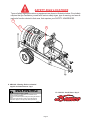
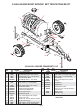
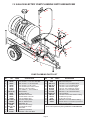
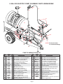
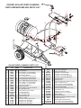
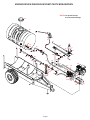
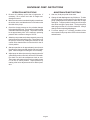
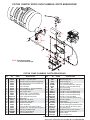
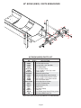
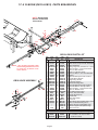
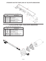
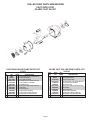
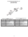
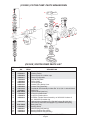
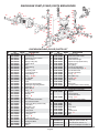
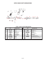
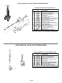
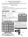
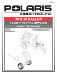
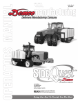
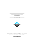
5-04 AS20001, Rev 3 DOING OUR BEST TO PROVIDE YOU THE BEST 55 GALLON LAWN & GARDEN SPRAYER OPERATORS MANUAL READ complete manual CAREFULLY BEFORE attempting operation. ASSEMBLY CALIBRATION OPERATION REPLACEMENT PARTS DEMCO Dethmers Mfg. Co. 4010 320th St. P.O. Box 189 Boyden, IA 51234 PH: (712) 725-2311 Toll Free: 1-800-543-3626 FAX: 1-800-845-6420 www.demco-products.com Page 1 Thank you for purchasing a Demco sprayer. We feel you have made a wise choice and hope you are completely satisfied with your new sprayer. If you have any questions regarding the applications of certain solutions or chemicals, contact your chemical supplier and follow chemical manufacturer recommendations as well as all licensing and use restrictions or regulations. WARNING To prevent serious injury or death ï Refer to chemical supplier and manufacturer recommendations and all licensing restrictions or regulations. ï Always wear recommended protective clothing when working with chemicals or sprayer. ï Dispose of all unused chemicals or solutions in proper and ecologically sound manner. Improper use can injure people, animals, plants and soil. GENERAL INFORMATION 1. Unless otherwise specified, high-strength (grade5) (3 radial-line head markings) hex head bolts are used throughout assembly of this sprayer. 3. When placing a parts order, refer to this manual for proper part numbers and place order by PART NO., DESCRIPTION, and COLOR. 2. Whenever terms "LEFT" and "RIGHT" are used in this manual it means from a position behind sprayer and facing forward. Table of Contents General information .............................................................................................................................. 2 Safety Sign Locations .......................................................................................................................... 3 Bolt Torque ........................................................................................................................................... 4 Skid Mount with the Trailer Kit Parts Breakdown and Parts List ............................................................ 5 1.5 Gallon Electric Pump Plumbing Parts Breakdown and Parts List .............................................. 6 5 Gallon Electric Pump Plumbing Parts Breakdown and Parts List ................................................. 7 PTO Roller Pump Plumbing Parts Breakdown and Parts List .......................................................... 8 Gas Engine Roller Pump Plumbing Parts Breakdown and Parts List ............................................ 9-10 Gas Engine Diaphragm Pump Plumbing Parts Breakdown and Parts List ................................... 10-11 Gas Engine Diaphragm Pump Operation and Maintenance Instructions ....................................... 12 Gas Engine Piston Pump Plumbing Parts Breakdown and Parts List ............................................. 13 80 Boom Parts Breakdown and Parts List ...................................................................................... 14 12 and 18 Boom Parts Breakdown and Parts List ......................................................................... 15 1.5 G.P.M. Electric Pump Parts Breakdown and Parts List ............................................................... 16 5 G.P.M. Electric Pump Parts Breakdown and Parts List .................................................................. 16 C4101 & XL4101 Pump Parts Breakdown and Parts List ............................................................... 17 C6500D & XL6500 Pump Parts Breakdown and Parts List ............................................................. 18 Piston Pump Parts Breakdown and Parts List ................................................................................. 19 Diaphragm Pump Parts Breakdown and Parts List ......................................................................... 20 Spray Wand Parts Breakdown and Parts List .................................................................................. 21 Bypass Valve Parts Breakdown and Parts List ................................................................................. 22 Single Section Valve Parts Breakdown and Parts List ..................................................................... 22 Sprayer Calibration .......................................................................................................................... 23 Sprayer Checklist ............................................................................................................................... 24 Page 2 SAFETY SIGN LOCATIONS Types of safety sign and locations on equipment are shown in illustration below. Good safety requires that you familiarize yourself with various safety signs, type of warning, and area or particular function related to that area, that requires your SAFETY AWARENESS. B A B A. AB21014 - Warning: Refer to chemical supplier and manufacturer Qty. 1 WARNING B. AA21012 - Small Demco Qty. 2 To prevent serious injury or death • Refer to chemical supplier and manufacturer recommendations and all licensing restrictions or regulations. • Always wear recommended protective clothing when working with chemicals or sprayer. • Dispose of all unused chemicals or solutions in proper and ecologically sound manner. Improper use can injure people, animals, plants and soil. 01/00 AB21014 Page 3 BOLT TORQUE TORQUE DATA FOR STANDARD NUTS, BOLTS, AND CAPSCREWS. Tighten all bolts to torques specified in chart unless otherwise noted. Check tightness of bolts periodically, using bolt chart as guide. Replace hardware with same grade bolt. NOTE: Unless otherwise specified, high-strength Grade 5 hex bolts are used throughout assembly of equipment. Bolt Torque for Standard bolts * Torque Specifications A 1/4 5/16 3/8 7/16 1/2 9/16 5/8 3/4 7/8 1 GRADE 2 lb-ft (N.m) GRADE 5 lb-ft (N.m) GRADE 8 lb-ft (N.m) 6 10 20 30 45 70 95 165 170 225 9 18 30 50 75 115 150 290 420 630 12 25 45 80 115 165 225 400 650 970 (8) (13) (27) (40) (60) (95) (130) (225) (230) (300) (12) (25) (40) (70) (100) (155) (200) (390) (570) (850) (16) (35) (60) (110) (155) (220) (300) (540) (880) (1310) Bolt Torque for Metric bolts * A Torque figures indicated are valid for non-greased or non-oiled threads and heads unless otherwise specified. Therefore, do not grease or oil bolts or capscrews unless otherwise specified in this manual. When using locking elements, increase torque values by 5%. * GRADE or CLASS value for bolts and capscrews are identified by their head markings. 6 7 8 10 12 14 16 18 20 22 24 CLASS 8.8 lb-ft (N.m) CLASS 9.8 lb-ft (N.m) CLASS 10.9 lb-ft (N.m) 9 15 23 45 78 125 194 268 378 516 654 10 18 25 50 88 140 216 ----- 13 21 31 61 106 170 263 364 515 702 890 GRADE-2 CLASS 8.8 (13) (21) (31) (61) (106) (169) (263) (363) (513) (699) (886) GRADE-5 CLASS 9.8 9.8 8.8 Page 4 (14) (24) (34) (68) (118) (189) (293) ----- GRADE-8 CLASS 10.9 10.9 (17) (29) (42) (83) (144) (230) (357) (493) (689) (952) (1206) 55 GALLON SKID MOUNT SPRAYER WITH TR55CB (TRAILER KIT) 18 3 4 1 17 5 8 14 6 16 7 12 7 2 11 7 9 28 13 9 24 7 19 26 29 7 19 10 7 9 21 7 26 20 19 7 9 22 27 25 23 55 GALLON SPRAYER FRAME PARTS LIST REF. NO. 1. 2. 3. 4. 5. 6. 7. 8. 9. 10. 11. 12. 13. 14. 15. 16. 17. 18. 20. 29. PART QTY. NO. REQD DESCRIPTION 5316 2 50" Strap Assembly 00004 2 5/16î Flatwasher 02802 2 5/16"-18 UNC Nylon Insert Locknut 04352 2 5/16"-18 UNC x 4" F.T. Hex Hd. Bolt 04353 50" Nylon Strap Black 05785-95 2 Small Strap Anchor - 1-3/4" Strap 00214 4 1/4 Flatwasher 00907 8 3/8"-16 UNC x 1" Hex Head Bolt 00955 2 1/4"-20 UNC x 1" Round U-Bolt 02592 12 3/8"-16 UNC Nylon Insert Locknut 02625-10 1 Trailer Main Frame 02630-10 1 Right Hose Storage Bracket 02631-10 1 Left Hose Storage Bracket 02632-10 1 Control Valve Mount 02633-10 1 Right Boom Mount 02634-10 1 Left Boom Mount (not shown) 02772 4 1/4"-20 UNC Nylon Insert Locknut P55 23 1 55 gal. Poly Tank P55 23A 1 55 gal. Poly Tank w/ Agitation Installed PL5A 1 5" dia. Lid w/ O-ring 00095 1 3/8-16 UNC x 3/4" Sq. Hd. Set Screw 02529 2 3/8-16 UNC x 2-1/2 Round U-Bolt REF. NO. 19. 20. 7. 21. 9. 22. 23. 24. 25. 26. 27. 28. Page 5 PART QTY. NO. REQD DESCRIPTION TR55CB 55 Gallon Trailer Kit 00059 8 3/8" Flatwasher 00095 4 3/8-16 UNC x 3/4" Sq. Hd. Set Screw 00907 14 3/8"-16 UNC x 1" Hex Head Bolt 01404-95 1 Lock Handle 02592 14 3/8"-16 UNC Nylon Insert Locknut 02626-10 1 Tongue 02627-10 1 Clevis Hitch 02628-10 1 Axle 02629-10 1 Safety Stand 02635-95 4 Wheel Space Collar TW18X8 2 18" x 9-1/2 x 8", 2 ply High Flotation Tire and Hub 02642 1 Bearing (only) 02643 2 Retainer (only) 02669-10 1 Valve Mount (red) Please order replacement parts by PART NO., COLOR, and DESCRIPTION. 1.5 GALLON ELECTRIC PUMP PLUMBING PARTS BREAKDOWN 33 23 22 13 14 16 23 32 14 4 23 17 23 21 29 26 6 27 24 7 25 23 9 23 12 23 18 19 30 20 2 35 1 12 5 11 8 1 10 31 5 34 23 28 3 5 PUMP PLUMBING PARTS LIST REF. PART QTY. NO. NO. REQD DESCRIPTION 1. 00214 6 1/4" Flatwasher 2. 00336 4 1/4"-20 UNC x 1-1/4" Hex Head Bolt 3. 00907 1 3/8"-16 UNC x 1" Hex Head Bolt 4. 00955 1 1/4"-20 UNC x 2" Rd. U-bolt 5. 02772 7 1/4"-20 UNC Nylon Insert Locknut 6. 03900 1 3/8" FPT x 3/8" FPT Valve 7. 04055 1 1/4"-20UNC x 1" Hex Head Bolt 8. 04755-95 1 Switch Mount 9. 04764 1 10 Wire Harness 10. 05020 2 Male Bullet Connector 11. 05021 2 Female Bullet Connector 12. 120RB 1/2" I.D Rubber Hose 13. 30L 22425 18 1 18" Hand Spray Wand 14. 380RB 3/8" I.D. Rubber Hose 16. 5500 6PP 1 Adjustable Tip 17. 60GB 1 60 lb. Pressure Gauge 18. 8000 543 150 1 12 Volt Electric Pump 19. 8027 1 Swivel Nut 20. 8079NY 1 50 Mesh Poly Strainer 21. A1238 1 1/2" MPT x 3/8" Hose Barb REF. PART QTY. NO. NO. REQD DESCRIPTION 22. A1438 1 1/4" MPT x 3/8" Hose Barb Fitting 23. B6H 8 3/8" Hose Clamp SS 24. BEL1212 1 1/2" MPT x 1/2" Hose Barb Elbow 25. BEL3412 1 3/4" MPT x 1/2" Hose Barb Elbow 26. BM1238 1 1/2" MPT x 3/8" Reducer Nipple 27. BTT12G 1 1/2" FPT Tee (Tapped for Gauge) 28. EL3812 1 3/8" MPT x 1/2" Hose Barb Elbow 29. EL3838 1 3/8" MPT x 3/8" Hose Barb Elbow 30. K8400 1/2 1 1/2" Hose Barb 31. NB1614 1 1/4" MPT x11/16" MPT Strainer Fitting 32. P55 23 1 55 Gallon Poly Tank 33. PL5A 1 5" dia. Lid w/ O-ring 34. RB3814 1 3/8" MPT x 1/4" FPT Reducer Fitting 35. 05004 2 Female Push on Connector (connects to back of toggle switch) Please order replacement parts by PART NO. and DESCRIPTION. Page 6 5 GALLON ELECTRIC PUMP PLUMBING PARTS BREAKDOWN 34 20 21 17 16 21 17 33 4 32 21 28 23 12 25 18 30 26 21 21 35 a b d 23 9 22 14 21 6 27 15 31 21 24 14 29 7 1 36 14 22 2 21 1 21 5 8 11 10 13 5 21 14 23 3 NOTE: Use thread sealant on all threaded fittings. 5 PUMP PLUMBING PARTS LIST REF. PART QTY. NO. NO. REQD DESCRIPTION 1. 00214 6 1/4" Flatwasher 2. 00336 4 1/4"-20 UNC x 1-1/4" Hex Head Bolt 3. 00907 1 3/8"-16 UNC x 1" Hex Head Bolt 4. 00955 1 1/4"-20 UNC x 2" Rd. U-bolt 5. 02772 7 1/4"-20 UNC Nylon Insert Locknut 6. 03900 1 3/8" FPT x 3/8" FPT Valve 7. 04055 1 1/4"-20UNC x 1" Hex Head Bolt 8. 04755-95 1 Switch Mount 9. 04764 1 10 Wire Harness 10. 05020 2 Male Bullet Connector 11. 05021 2 Female Bullet Connector 12. 100GB 1 100 lb. Brass Pressure Gauge 13. 10983 1 Electric 12 VDC Pump (5 GPM) 14. 120RB 1/2" I.D Rubber Hose 15. 23120PP 1 1/2" NPT Pressure Relief Valve 16. 30L-18PP 1 18" Hand Spray Wand 17. 380RB 3/8" I.D. Rubber Hose 18. 5044 1 1 Single Aggitation Wand Assembly 20. A1438 1 1/4" MPT x 3/8" Hose Barb Fitting 21. B6H 12 3/8" Hose Clamp SS REF. PART QTY. NO. NO. REQD DESCRIPTION 22. BA1212 2 1/2" MPT x 3/8" Hose Barb 23. BEL1212 3 1/2" MPT x 1/2" Hose Barb Elbow 24. BEL3412 1 3/4" MPT x 1/2" Hose Barb Elbow 25. BM1238 1 1/2" MPT x 3/8" MPT Reducer Nipple 26. BRB114 34 1 1-1/4î MPT x 3/4î Reducer Fitting 27. BTT12G 1 1/2" FPT Tee (Tapped for Gauge) 28. EL1438 1 1/4" MPT x 3/8" Hose Barb Elbow 29. EL3838 1 3/8" MPT x 3/8" Hose Barb Elbow 30. M1200 1 1/2î MPT Nipple 31. P012DSW 1 1/2î Double Thread Spin Weld Fitting 32 P114PAVSW 1 1-1/4î Anti-Vortex Spin Weld Fitting 33. P55 23A 1 55gal. Poly Tank 34. PL5A 1 5" dia. Lid w/ O-ring 35. RVB12 80 1 Strainer Assembly w/ 80 mesh screen a. RVF38C 1 1/2 Strainer Cup b. RVB80 1 80 Mesh Screen for 1/2 Strainer c. RVB38GE 1 Viton 0-Ring (not shown) d. RVB38B 1 Strainer Bowl 36. 05004 2 Female Push on Connector (connects to back of toggle switch) Please order replacement parts by PART NO. and DESCRIPTION. Page 7 (TR55RP) ROLLER PUMP PLUMBING PARTS BREAKDOWN AND PARTS LIST 20 17 24 28 11 28 19 16 19 2 28 41 18 28 25 18 23 33 21 32 39 33 26 32 34 8 40 18 44 26 32 43 37 15 36 26 22 26 26 30 45 28 31 28 29 39 33 34 32 a 33 b c 38 d 26 33 30 6 5 27 39 34 26 32 10 26 7 3 26 32 35 18 26 4 2 32 13 12 8 1 14 9 R0LLER PUMP PLUMBING PARTS LIST REF. PART QTY. NO. NO. REQD DESCRIPTION 1. 00036 2 5/16" Lockwasher 2. 00214 5 1/4" Flatwasher 3. 00907 1 3/8-16 UNC x 1 Hex Head Bolt 4. 01076 1 1/4-20 UNC x 3/4 Hex Head Bolt 5. 02150-95 1 Tee Mounting Bracket 6. 02592 1 3/8-16 UNC Nylon Insert Locknut 7. 02616-10 1 Vertical Strainer Mounting Bracket 8. 02772 5 1/4"-20 UNC Nylon Insert Locknut 9. 02802 1 5/16-18 UNC Nylong Insert Locknut 10. 02990 1 5/16-18 UNC x 1 Hex Head Bolt 11. 04055 4 1/4-20 UNC x 1 Hex Head Bolt 12. 04298-70 1 Pump Mounting Bracket 13. 04299 1 Roller Pump Chain 14. 04305 2 5/16"-18 UNC x 1/2" Hex Head Bolt 15. 120RB 1/2" I.D Rubber Hose 16. 160GB 1 160 lb. Brass Pressure Gauge 17. 30L22425 18 1 18" Hand Spray Gun 18. 340RB 3/4" I.D Rubber Hose 19. 380RB 3/8" I.D. Rubber Hose 20. 5500 18PP 1 Adjustable Spray Tip 21. 6B1 1 Direct - o - valve 22. 8460 1 3/4" MPT Pressure Relief Valve 23. A1238 1 1/2" MPT x 3/8" Hose Barb 24. A1438 1 1/4î MPT x 3/8 Hose Barb 25. A3438 1 3/4" MPT x 3/8" Hose Barb 26. B12H 10 27. B24H 2 28. B6H 6 29. BA3412 1 30. BA3434 2 31. BEL1212 1 32. BEL3434 7 33. BM3400 5 34. BTT34 3 35. C6500D 1 XL6500D 1321 0012 1 36. EL114 34 1 37. M1200 1 38. RVF34 80 1 a. RVF34C 1 b. RVF34GV 1 c. RVF380 1 d. RVF34B 1 39. UV075FP 3 40. P55 23A 1 41. PL5A 1 43. 5044 1 1 44. P114PAVSW 1 45. P012DSW 1 3/4" Hose Clamp SS 1-1/4 Hose Clamp SS 3/8" Hose Clamp SS 3/4" MPT x 1/2" Hose Barb 3/4" MPT x 3/4" Hose Barb 1/2" MPT x 1/2" Hose Barb Elbow 3/4" MPT x 3/4" Hose Barb Elbow 3/4" MPT Nipple 3/4" FPT Tee Cast Iron Roller Pump w/Quick Coupler Silver Cast Roller Pump Quick Coupler Adapter (540 RPM) 1-1/4" MPT x 3/4" Hose Barb Elbow 1/2" MPT Short Nipple 3/4" Line Strainer w/80 mesh screen 3/4" Strainer Cup Viton O-ring for 3/4" Strainer 80 Mesh Screen for 3/4" Strainer Strainer Bowl 3/4" Poly Ball Valve 55 Gallon Poly Tank w/ Agitation Installed 5" dia. Lid w/ O-ring Single Agitation Wand Assembly 1-1/4 Anti-Vortex Spin Weld Fitting 1/2 Double Thread Spin Weld Fiting Please order replacement parts by PART NO. and DESCRIPTION. Page 8 ENGINE DRIVEN ROLLER PUMP PLUMBING PARTS BREAKDOWN 41 40 20 17 24 27 27 44 43 16 19 37 B 11 27 36 26 18 26 45 2 19 31 28 A 30 15 23 39 27 34 32 26 18 18 26 30 C 32 26 30 39 21 33 33 25 22 18 8 26 28 26 a 33 30 13 b 34 c 14 18 32 38 d 5 26 18 3 10 32 10 6 9 26 28 35 D 26 29 30 39 7 1 12 30 4 9 18 33 34 9 26 32 NOTE: Use thread sealant on all threaded fittings. OPERATING INSTRUCTIONS 1. Fill the tank with water. 6. Start and run pump. 2. Open the Ball valve (A) in the pump intake line. 7. Slowly close the pressure relief valve (B) until the desired spraying pressure is reached with the boom spraying. 3. Open (counter clockwise) the pressure relief valve (B). 8. 4. Open the Tee valve (C) so that all the boom sections are spraying. If adequate spraying pressure cannot be reached, slowly close the agitation valve (D) until the desired spraying pressure is reached. 5. Open the agitation valve (D). 9. Check for leaks. Page 9 ENGINE DRIVEN ROLLER PUMP PLUMBING PARTS LIST REF. PART QTY. NO. NO. REQD DESCRIPTION 1. 00036 2 5/16" Lockwasher 2. 00214 4 1/4" Flatwasher 3. 00372 4 5/16"-18 UNC x 1-1/2" Hex Head Bolt 4. 01872 2 Rubber Bumper 5. 02653-70 1 Pump Drive Shaft Shield 6. 02658-10 1 Engine Mounting Plate 7. 02660-70 1 Pump Mounting Bracket 8. 02772 4 1/4"-20 UNC Nylon Insert Locknut 9. 02802 9 5/16-18 UNC Nylon Insert Locknut 10. 02990 5 5/16-18 UNC x 1 Hex Head Bolt 11. 04055 4 1/4-20 UNC x 1 Hex Head Bolt 12. 04305 2 5/16"-18 UNC x 1/2" Hex Head Bolt 13. 04880-95 1 Pump Coupler 14. 07174 4 Coupler Set Screws 15. 120RB 1/2" I.D Rubber Hose 16. 160GB 1 160 lb. Brass Pressure Gauge 17. 30L22425 18 1 18" Hand Spray Gun 18. 340RB 3/4" I.D Rubber Hose 19. 380RB 3/8" I.D. Rubber Hose 20. 5500 18PP 1 Adjustable Spray Tip 21. 6B1 1 Direct - o - valve 22. 8460 1 3/4" MPT Pressure Relief Valve 23. A1238 1 1/2" MPT x 3/8" Hose Barb 24. A1438 1 1/4 MPT x 3/8 Hose Barb 25. A3438 1 3/4" MPT x 3/8" Hose Barb REF. NO. 26. 27. 28. 29. 30. 31. 32. 33. 34. 35. 36. 37. 38. a. b. c. d. 39. 40. 41. 43. 44. 45. PART QTY. NO. REQD DESCRIPTION B12H 12 3/4" Hose Clamp SS B6H 6 3/8" Hose Clamp SS GE3HP 1 3-1/2 H.P. Briggs Gas Engine GH4HP 4 H.P. Honda Gas Engine BA3412 1 3/4" MPT x 1/2" Hose Barb BA3434 6 3/4" MPT x 3/4" Hose Barb BEL1212 1 1/2" MPT x 1/2" Hose Barb Elbow BEL3434 5 3/4" MPT x 3/4" Hose Barb Elbow BM3400 4 3/4" MPT Nipple BTT34 3 3/4" FPT Tee C4101 1 Cast Iron Roller Pump XL4101 1 Silver Cast Roller Pump EL114 34 1 1-1/4" MPT x 3/4" Hose Barb Elbow M1200 1 1/2" MPT Short Nipple RVF34 80 1 3/4" Line Strainer w/80 mesh screen RVF34C 1 3/4" Strainer Cup RVF380 1 80 Mesh Screen for 3/4" Strainer RVF34GV 1 Viton O-ring for 3/4" Strainer RVF34B 1 Strainer Bowl UV075FP 3 3/4" Poly Ball Valve P55 23A 1 55 Gallon Poly Tank w/ Agitation Installed PL5A 1 5" dia. Lid w/ O-ring 5044 1 1 Single Agitation Wand Assembly P114PAVSW 1 1-1/4 Anti-Vortex Spin Weld Fitting P012DSW 1 1/2 Double Thread Spin Weld Fiting Please order replacement parts by PART NO. and DESCRIPTION. DIAPHRAGM PUMP PLUMBING PARTS LIST REF. PART QTY. NO. NO. REQD DESCRIPTION 1. 00004 8 5/16" Flatwasher 2. 00214 4 1/4" Flatwasher 3. 00372 4 5/16"-18 UNC x 1-1/2" Hex Head Bolt 4. 02615-10 2 Diaphragm Pump Mounting Bracket 5. 02772 4 1/4"-20 UNC Nylon Insert Locknut 6. 02802 8 5/16-18 UNC Nylong Insert Locknut 7. 02990 4 5/16-18 UNC x 1 Hex Head Bolt 8. 04055 4 1/4-20 UNC x 1 Hex Head Bolt 9. 160GBF 1 160 lb. Brass Pressure Gauge Liquid Filled 10. 30L22425 18 1 18" Hand Spray Gun 11. 340RB 3/4" I.D Rubber Hose 12. 380RB 3/8" I.D. Rubber Hose 13. 5500 18PP 1 Adjustable Spray Tip 14. 580RB 5/8 I.D. Rubber Hose 15. 6B1 1 Direct - o - valve 16. 9910D19GRGI 1 Diaphragm Pump 17. A1238 1 1/2" MPT x 3/8" Hose Barb 18. A1438 1 1/4 MPT x 3/8 Hose Barb 19. A3438 3 3/4" MPT x 3/8" Hose Barb 20. B12H 6 3/4" Hose Clamp SS 21. B6H 10 3/8" Hose Clamp SS 22. B8H 2 1/2 Hose Clamp SS 23. BA3434 3 3/4" MPT x 3/4" Hose Barb REF. PART QTY. NO. NO. REQD DESCRIPTION 24. BEL3434 1 3/4" MPT x 3/4" Hose Barb Elbow 25. BM3400 3 3/4" MPT Nipple 26. BTT34 2 3/4" FPT Tee 27. EL114 34 1 1-1/4" MPT x 3/4" Hose Barb Elbow 28. EL1238 1 1/2" MPT x 3/8" Hose Barb Fitting 29. EL3438 1 3/4" MPT x 3/8" Hose Barb 30. EL3458 1 3/4" MPT x 5/8" Hose Barb 31. F3400 1 3/4 MPT Plug 32. GE3HP 1 3-1/2 H.P. Briggs Gas Engine GH4HP 4 H.P. Honda Gas Engine 33. RVF34 80 1 3/4" Line Strainer w/80 mesh screen a. RVF34C 1 3/4" Strainer Cup b. RVF380 1 80 Mesh Screen for 3/4" Strainer c. RVF34GV 1 Viton O-ring for 3/4" Strainer d. RVF34B 1 Strainer Bowl 34. UV075FP 3 3/4" Poly Ball Valve 35. P55 23A 1 55 Gallon Poly Tank w/ Agitation Installed 36. PL5A 1 5" dia. Lid w/ O-ring 38. 5044 1 1 Single Agitation Wand Assembly 39. P114PAVSW 1 1-1/4 Anti-Vortex Spin Weld Fitting 40. P012DSW 1 1/2 Double Thread Spin Weld Fiting 41. M1200 1 1/2 MPT Short Nipple Please order replacement parts by PART NO. and DESCRIPTION. Page 10 ENGINE DRIVEN DIAPHRAGM PUMP PARTS BREAKDOWN NOTE: Use thread sealant on all threaded fittings. 36 35 13 10 18 21 21 39 38 9 41 12 12 12 40 8 21 27 20 19 28 21 21 11 31 19 17 34 21 19 21 20 23 2 23 25 15 34 25 26 34 20 12 21 30 11 5 29 12 20 23 a 32 22 25 14 16 b c 26 d 21 24 33 20 11 3 22 20 21 6 12 4 7 1 Page 11 1 6 DIAPHRAGM PUMP INSTRUCTIONS OPERATION INSTRUCTIONS MAINTENANCE INSTRUCTIONS 1. Be sure oil is halfway up the clear oil sight tube. If necessary, fill to correct level with 30 weight nondetergent motor oil. 1. After use, flush pump with clean water. 2. Change oil and diaphragms every 500 hours. To drain oil from the pump, remove cap from oil sight tube, turn pump upside down and rotate the shaft until oil stops flowing out. To fill pump with oil, slowly pour oil into sight tube while turning the pump shaft. Turning the pump shaft purges all the air out of the crankcase. Always change oil when replacing diaphragms. 2. Make sure the suction hose barb is tightly screwed onto the suction union, and that there are no air leaks on the inlet side of the pump. 3. Check the charge pressure on the pulsation damper before starting the pump. The pressure is checked with a standard automotive air gauge. The pressure should be at approximately 20% of the maximum operating pressure with a minimum charge of 10 PSI. 3. For winter storage or if a freezing condition will be encountered, flush pump with a 50/50 mixture of water and antifreeze. 4. Allow the pump to start under low pressure by removing restrictions on the outlet of the pump. The restriction on the pump is removed by rotating the red knob on the control unit so that the letter A on the knob is in the 12 o'clock position. 5. Start pump and let run for approximately one minute at low pressure. Stop pump and check the oil level in sight glass. Add 30 weight non-detergent oil if necessary. 6. Adjust pump to desired pressure by changing the relief valve setting on the control unit, relief valve or unloader. First back out relief valve adjustment knob to zero. Then rotate red bypass selector knob so that the letter C is in the 12 o'clock position. Adjust pressure by rotating relief valve adjustment knob to desired pressure. Page 12 PISTON PUMP W/ SPRAY GUN PLUMBING PARTS BREAKDOWN 23 5 9 32 38 36 27 13 34 a c b 32 31 24 28 d 27 22 37 7 28 24 29 14 25 17 27 30 1 16 15 35 31 1 28 NOTE: Use thread sealant on all threaded fittings. 10 6 21 22 28 26 20 1 4 19 16 33 2 8 12 3 11 11 18 PISTON PUMP PLUMBING PARTS BREAKDOWN REF. PART QTY. REF. PART QTY. NO. NO. REQD DESCRIPTION NO. NO. REQD DESCRIPTION 23. 23H 1 Spray Gun (less wand & tip) 1. 00014 3 1/2" MPT Close Nipple-Steel 4006 1 Main Spraying Tip 2. 00016 1 1/2" MPT x 1/2" FPT-Steel 0006 1 Brass Cutting Tip 3. 00021 1 1/2" MPT x 3/8" FPT Reducer Fitting-Steel 24. 340RB 3/4" I.D Rubber Hose 4. 00022 1 3/8" High Pressure Hose w/couplers (35') 25. 6815BR 1 1/2" Pressure Relief Valve (700 psi.) 5. 00024 1 3/8" Swivel Fitting 26. A3812 1 3/8" MPT x 1/2" Hose Barb Fitting 6. 00059 4 3/8" Flatwasher 27. B12 4 3/4" Hose Clamp 7. 00372 4 5/16"-18 UNC x 1-1/2" Hex Head Bolt 28. B8H 4 1/2" Hose Clamp 8. 00536 1 1/2" Street Elbow-Steel 29. BA1212 1 1/2" MPT x 1/2" Hose Barb Fitting 9. 00817 1 3/8" Coupler-Steel 30. BA1234 1 1/2" MPT x 3/4" Hose Barb Fitting 10. 00907 4 3/8"-16 UNC x 1" Hex Head Bolt 31. BEL1212 2 1/2" MPT x 1/2" Hose Barb Fitting 11. 02592 4 3/8"-16 UNC Nylon Insert Locknut 32. BEL3434 2 3/4" MPT x 3/4" Hose Barb 12. 02620-10 1 Piston Pump Mounting Plate 33. BM1238 1 1/2 MPT x 3/8 MPT Straight Fitting 13. 02621-10 1 Belt Guard 34. BM3400 1 3/4" MPT Nipple 14. 02752 1 Small Pully- 3/4" Shaft 35. C5330R 1 Piston Pump 15. 02753 1 Large Pulley- 5/8" Shaft - EL114 34 1 Tank Outlet Fitting (not shown) 16. 02773 2 1/2" FPT Cross-Galv 36. GE3HP 1 3.5 HP Gas Engine (Horizontal Shaft) 17. 02780 1 Piston Pump Belt 37. RVF34 80 1 3/4" Line Strainer (80 mesh screen) 18. 02802 4 5/16"-18 UNC Nylon Insert Locknut RVF34C 1 3/4" Strainer Cup 19. 02963 1 1/2 MPT x 1/4 FPT Reducer Fitting-Steel a. b. RVF380 1 80 Mesh Screen for 3/4" Strainer 20. 03900 1 3/8" FPT (2x) Brass Valve c. RVF34GV 1 Viton O-ring for 3/4" Strainer 21. 1000GBF 1 1000 p.s.i. Brass Gauge d. RVF34B 1 Strainer Bowl 22. 120RB 1/2" I.D Rubber Hose 38. UV075FP 1 3/4" Poly Ball Valve Page 13 80" BOOM (80B25) PARTS BREAKDOWN 11 17 12 19 3 8 12 11 49 10 1 17 20 7 8 4 12 18 9 6 80" BOOM (80B25) PARTS LIST REF. PART QTY. NO. NO. REQD DESCRIPTION 1. 00004 4 5/16" Flatwasher 2. 00062 2 1/4"-20 UNC Hex Nut 3. 00068 2 1/4"-20 UNC x 3/4" Hex Bolt 4. 00059 8 3/8" Flatwashers 5. 00337-95 4 1-1/4" Boom Clamp 6. 00909 2 5/16"-18 UNC x 1-1/4" Sq. U-bolt 7. 02253-10 1 Center Boom 8. 02678-95 2 Boom Mounting Plate 9. 02592 4 3/8"-16 UNC Nylon Insert Locknut 10. 02802 4 5/16"-18 UNC Nylon Insert Locknut 11. 02529 2 3/8"-16 UNC x 1-1/2" Round U-bolt 12. 380RB - 3/8" I.D. Rubber Hose 13. 4193APP50 2 5 PSI Ball Check Strainer 14. 8027 2 11/16" FPS Swivel Nut 15. AN1.5 2 Flood Jet Spray Tip 16. B12 2 Nozzle Nut 17. B6H 6 3/8" Hose Clamp 18. NHT11 1 Hose Tie 19. NTL38 2 3/8" Elbow Spray Nozzle Fitting (w/nut) 20. T38 1 3/8" Hose Barb Insert Tee Please order replacement parts by PART NO. and DESCRIPTION. Page 14 2 17 6 5 16 13 15 14 12' & 18í BOOM (DB12 & DB18) PARTS BREAKDOWN NOTE: Boom shown below is model DB12 12 foot boom 23 25 4 17 3 10 5 23 15 3 10 23 26 10 24 31 6 30 2 32 22 20 7 19 21 1 11 1 12 8 14 15 18 9 29 23 24 DB12 & DB18 PARTS LIST 23 13 REF. NO. PART NO. QTY. REQD DB12 00004 11137 00059 00340-95 00357 00640 00909 00967 01564 02592 02636-10 02637-10 02638-10 02678-95 02772 02529 380RB 1 4 2 8 2 2 2 2 2 2 6 1 1 1 2 8 2 4 4 4 4 8 3 2 2 1 DB18 1 12' & 18' Boom Assembly 00004 4 5/16 Flatwasher 11137 2 3/8î Clinch Nut (inclíd with 00340-95) 00059 8 3/8" Flatwasher 00340-95 2 Wing Hinge Pin (includes two 11137) 00357 4 3/8"-16 UNC x 4-1/2" Tension Bolt 00640 2 1/2-13 UNC Jam Nut 00909 5 5/16" x 1-3/8" Sq. U-bolt 00967 2 1/2-13 UNC x 1-1/4 Hex Head Bolt 01564 4 Spring 02592 8 3/8"-16 UNC Nylon Insert Locknut 03673-10 1 Center Boom Section 03675-10 1 Right Wing Section 03680-10 1 Left Wing Section 02678-95 2 Boom Mounting Plate 02772 14 1/4"-20 UNC Nylon Insert Locknut 04822 3 1/4-20 UNC x 1-1/2 Sq. U-bolt 02529 2 3/8"-16 UNC x 1-1/2" Round U-bolt 380RB - 3/8" I.D. Rubber Hose 4193APP50 6 5 PSI Ball Check Valve 8027 6 11/16" FPS Swivel Nut AN1.5 6 Flood Jet Spray Tip B12 6 Nozzle Nut B6H 12 3/8" Gear Clamp NHT11 12 Hose Tie NTL38 2 3/8" Elbow Spray Nozzle Fitting w/nut NTT38 4 3/8" Tee Nozzle Fitting w/nut 03674-10 2 Spring Anchor Angle (DB18 Only) 03676-10 1 Boom Support Plate (DB18 Only) T38 1 3/8" Insert Tee 4 1 1 2 B11 114 00062 00068 00337-95 1. 2. 3. NOTE: The mounting brackets (#14) 4. and attaching hardware are used to mount the 18' Boom in the 5. same manner. 6. 7. 8. 9. 10. 11. 12. 16 DB18 HINGE ASSEMBLY 13. 14. 15. 16. 17. 5 15 28 18. 4 15 19. 4193APP50 27 20. 8027 9 21. AN1.5 22. B12 23. B6H 16 24.. NHT11 10 25. NTL38 26. NTT38 27. 28. 29. T38 2 B11 114 30. 00062 31. 00068 32. 00337-95 PART NO. QTY. REQD 6 1 1 2 DESCRIPTION 1-1/4 Boom Clamp Assembly 1/4"-20 UNC Nut 1/4"-20 UNC x 3/4" Hex Hd. Bolt 1-1/4" Boom Clamp Please order replacement parts by PART NO. and DESCRIPTION. Page 15 STANDARD ELECTRIC PUMP (8000 543 150) PARTS BREAKDOWN 2 3 1 4 ELECTRIC PUMP (8000 543 150) PARTS LIST REF. NO. 1. 2. 3. 4. 5. PART NO. 94 382 09 94 378 00 94 391 09 94 395 06 94 385 03 DESCRIPTION Pumphead complete w/viton parts Upper Housing Kit Viton Valve Kit Santoprene Diaphragm Kit Lower Housing Drive assembly 3.0 degree Cam 6. 94 370 03 Motor and Base Assembly Please order replacement parts by PART NO. and DESCRIPTION. 5 6 5 G.P.M. ELECTRIC PUMP (10983) PARTS BREAKDOWN OPT. ELECTRIC PUMP (10983) PARTS LIST REF. PART NO. NO. 1. 120RB 2. 11261 3. 11260 4. B6H 5. 11262 6. RVB12 80 7. BA1212 8. BEL1212 DESCRIPTION 1/2î I.D. Rubber Hose Valve Housing Assembly Lower Housing Assembly 3/8î Hose Clamp Upper Housing Assembly 1/2" MPT x 1/2" Hose Barb Bowl Filter 1/2" MPT x 1/2" Hose Barb 1/2" MPT x 1/2" Hose Barb Elbow Please order replacement parts by PART NO. and DESCRIPTION. 6 4 3 1 2 4 7 5 8 Page 16 ROLLER PUMP PARTS BREAKDOWN CAST IRON C4101 SILVER CAST XL4101 2 11 3 10 9 8 7 13 5 4 3 2 1 6 SILVER CAST ROLLER PUMP PARTS LIST XL4101 CAST IRON ROLLER PUMP PARTS LIST C4101 REF. NO. 1. 2. 3. 4. 5. 6. 7. 8. 9. 10. - PART QTY. NO. REQD DESCRIPTION 0600 1 Name Plate (specify pump model #.) BAC37 2 Sealed Ball Bearing *2107 0002 2 Viton Seal (standard) 0200 4101C 1 End Plate (cast iron)w/standard seal *1720 0104 1 O-ring Gasket for End Plate 2200 0009 4 End Plate Screw 0300 4101C 1 Rotor (cast iron)and Shaft Assembly 0500 6600 1 Shaft ONLY 2230 0002 1 Rotor Set Screw 1005 0004 4 Super Rollers (standard) *1002 0002 4 Polypropylene Rollers (optional) 0100 4101C 1 Body (cast iron) w/standard seal 3430 0158 Repair Kit: contains items marked (*) REF. PART QTY. NO. NO. REQD DESCRIPTION 1. 0600 1 Name Plate (specify pump model #) 2. BAC37 2 Sealed Ball Bearing 3. *2107 0002 2 Viton Seal (standard) 4. 0200 4101X 1 End Plate (silver cast) w/standard seal 5. *1720 0104 1 O-ring Gasket for End Plate 6. 2200 0009 4 End Plate Screw 7. 0300 4101X 1 Rotor (silver cast) and shaft assembly 0500 6600 Shaft ONLY 8. 2230 0002 1 Rotor Set Screw 9. 1005 0004 4 Super Rollers (standard) *1002 0002 4 Polypropylene Rollers (optional) 10. 0100 4101X 1 Body (silver cast) w/standard seal 3430 0158 Repair Kit: contains items marked (*) Page 17 PTO DRIVEN ROLLER PUMP PARTS LIST CAST IRON C6500D SILVER CAST XL6500 2 9 3 10 6 7 8 5 4 3 2 1 CAST IRON ROLLER PUMP PARTS LIST C6500D SILVER CAST ROLLER PUMP PARTS LIST XL6500 REF. NO. PART NO. QTY. REQD 1. 2. 3. 4. 5. 6. 7. 8. 9. 10. - 0600 BAC37 *2107 0002 0200 6600 *1720 0008 *1005 0004 1002 0004 0300 6600 0500 6600 0100 6600 1321 0012 3430 0380 1 2 2 1 1 6 6 1 1 1 1 - DESCRIPTION Name Plate (specify pump model no.) Ball Bearing (sealed) Viton Seal (standard) End Plate (Silver Cast) (includes Seal #3) O-ring for End Plate Super Roller Polypropylene Roller (optional) Rotor with Shaft (Silver Cast) Shaft Only Body (Siver Cast) (includes Seal #3) Quick Coupler Adapter-Multi Speed Repair Kit: contains items marked (*) REF. NO. PART NO. QTY. REQD 1. 2. 3. 4. 5. 6. 7. 8. 9. 10. - 0600 BAC37 *2107 0002 0200 6600C *1720 0008 *1005 0004 1002 0004 0300 6600C 0500 6600 0100 6600C 1321 0012 3430 0380 1 2 2 1 1 6 6 1 1 1 1 - Page 18 DESCRIPTION Name Plate (specify pump model no.) Ball Bearing (sealed) Viton Seal (standard) End Plate (includes Seal #4) O-ring for End Plate Super Roller Polypropylene Roller (optional) Rotor with Shaft Shaft Only Body (includes Seal #4) Quick Coupler Adapter-Multi Speed Repair Kit: contains items marked (*) (C5330R ) PISTON PUMP PARTS BREAKDOWN 1 12 2 4 13 3 5 14 B C 15 16 11 D E 10 6 7 A 9 21 18 19 20 17 8 (C5330R ) PISTON PUMP PARTS LIST REF. NO. 1. 2. 3. 4. 5. 6. 7. 8. 9. 10. 11. 12. 13. 14. 15. 16. 17. 18. 19. 20. 21. PART QTY. NO. REQD DESCRIPTION 2220 0012 2 Piston Cap Screw 2270 0011 2 Washer Gasket 3430 0009 1 Piston Repair Kit w/rubber cups 1830 0017 2 Piston Cup Spreader 1410 0030 2 Cup Backing Plate 1440 0004 2 Piston Guide 0502 5300 1 Connecting Rod 0608 5300 1 Grease Fitting Safety Cover 2405 0006 1 Grease Fitting Assembly 5501 5330 1 Crankshaft Sub Assembly-includes Ref. # 14,13,& 11 with solid shaft 1610 0007 1 Spline Key 0200 5300C 2 Cylinder Head (cast iron) 1720 0038 2 O-ring for cylinder head 1720 0079 2 O-ring for cylinder sleeve 3550 0019 2 Ni-Resist Cylinder Sleeve Assembly: no.3350 0018 X sleeve & no. 1830 0033 X retainer ring 3400 0049 4 Unitized Valve: Consists of (A) 1720 0007 o-ring, (B) 3210 0015 valve seat (C) 3260 0002 valve poppet & (D) 1900 0030 valve spring 0100 5300C 1 Body (cast iron) 2130 0007 1 Bearing Shield 2008 0001 2 Main Bearing (ball bearing) 1810 0013 2 Bearing Retainer Ring (shaft) 1820 0006 1 Bearing Retainer Ring (housing) Please order replacement parts by PART NO. and DESCRIPTION. Page 19 DIAPHRAGM PUMP (D19GR) PARTS BREAKDOWN 49 70 76 58 68 72 1 73 74 6 71 75 59 70 63 5 7 77 8 4 3 2 45 52 44 13 24 57 25 18 29 17 14 21 22 40 27 34 37 36 32 39 38 35 26 28 13 15 31 41 43 30 23 64 13 42 51 66 65 61 47 46 50 11 9 54 53 67 12 10 55 56 69 66 68 65 48 13 16 DIAPHRAGM PUMP (D19GR) PARTS LIST REF. NO. 1. 2. 3. 4. 5. 6. 7. 8. 9. 10. 11. 12. 13. 14. 15. 16. 17. 18. 21. 22. 23. 24. 25. 26. 27. 28. 29. 30. 31. 32. 34. 35. 36. 37. 38. 39. 40. 41. 42. 43. PART QTY. NO. REQD DESCRIPTION 9910 800380 2 O-ring B, D 9910 800020 1 Front Housing 9910 800171 1 Crankshaft for G.R. Version 9910 800160 1 Spacer Washer 9910 800150 2 Spring Locking Clip 9910 800370 2 Retainer Knob 9910 800200 1 Seal 9910 800180 1 Roller Bearing 9910 800120 2 Piston 9910 800140 2 Connecting Rod 9910 800130 2 Connecting Rod Pin 9910 480370 1 Roller Bearing 9910 480440 7 O-ring A, B, C 9910 680360 1 Oil Tube Bolt 9910 800220 7 Head Bolt 9910 800100 2 Head 9910 800090 2 Diaphragm Retaining Bolt 9910 800350 2 Diaphragm Supporting Washer 9910 800085 2 Diaphragm A 9910 800110 2 Piston Sleeve 9910 740290 1 O-ring B 9910 800320 1 Oil Sight Glass 9910 800520 2 Barb Nut 9910 390180 1 O-ring B 9910 550450 1 Barb Nut 9910 800340 1 5/8" Inlet Elbow Hose Barb 9910 800540 1 1/2" Outlet Hose Barb 9910 800400 1 Relief Valve Body (w/Valve Seat) 9910 550331 2 Lockwasher 9910 800410 2 Bolt (6MA x 40) 9910 800430 1 Floating Valve 9910 800500 1 Locking Bolt 9910 800510 1 Locking Bolt Cap 9910 390330 1 Locking Pin 9910 800560 1 O-ring B 9910 800490 1 Positioning Rod 9910 800530 1 3/8" Outlet Hose Barb 9910 800670 1 5/8" Bypass Barb 9910 800680 1 Barb Nut 9910 770140 1 O-ring REF. NO. 44. 45. 46. 47. 48. 49. 50. 51. 52. 53. 54. 55. 56. 57. 58. 59. 60. 61. PART QTY. NO. REQD DESCRIPTION 9910 800480 1 Indicator Scale 9910 800440 1 Relief Valve Seat Holder 9910 800450 1 Tension Spring 9910 800460 1 Relief Valve Plunger 9910 800470 1 Adjustment Cap (Relief Valve) 9910 480550 1 Retainer Ring 9910 800010 1 Pump Body 9910 800330 1 Cap for Oil Sight Glass 9910 800190 1 Accumulator Diaphragm A 9910 800230 1 Accumulator Head 9910 800650 1 Air Valve Assembly 9910 390340 1 O-ring B 9910 540290 4 Bolt (8MA x 35) 9910 800210 2 O-ring A, B 9910 800360 2 Valve Cap 9910 800590 1 Key 9910 800311 1 Base Plate 9910 809060 1 Complete Relief Valve Assembly 63. 64. 65. 66. 67. 68. 69. 9910 809050 9910 800060 9910 200540 - 2 2 4 4 2 4 2 Complete Valve Assembly Check Valve Cage (Inlet) Poppet Tension Spring Check Valve Seat O-ring B, C Check Valve Cage (Outlet) 70. 71. 72. 73. 74. 75. 76. 77. 9910 9910 9910 9910 9910 9910 9910 9910 620301 390440 800280 800810 800820 800800 480820 620440 2 4 1 1 1 1 1 4 Plug Nut Gear Driver Gear Body Locating Bolt Seal D Bolt 9910 KIT1923 9910 KIT1913 9910 KIT1914 9910 KIT1950 - Repair Kits Diaphragm Kit (items marked A) O-Ring Kit (items marked B) Valve Kit (items marked C) Gear Box Seal Kit (items marked D) - C Please order replacement parts by PART NO. and DESCRIPTION. Page 20 SPRAY WAND PARTS BREAKDOWN 1 2 13 3 45 12 7 6 8 15 17 14 16 23 19 18 20 24 24 25 26 21 22 11 9 10 SPRAY WAND PARTS BREAKDOWN REF. NO. PART NO. 1. 2. 3. 4. 5. 6. 7. 8. 9. 10. 11. 12. 13. 14. 19684 1NYB 17013 1ZP 19818 1ZP 19819SS 19816 *22138 302SS 19815 19810 19805DEL 19806FRP 17703FRP 19820 420SS 17720 420SS 7622INP DESCRIPTION Housing Assembly Screw Screw Washer Spring Retainer Spring Spring Guide Trigger Guide Lock Spring Ring Trigger Lock Trigger Roll Pin Roll Pin #6 Burr REF. NO. 15. 16. 17. 18. 19. 20. 21. 22. 23. 24. 25. 26. PART NO. DESCRIPTION 7489 302SS 7484INP 19811 *19812AL *14255 1BU 22427 18SS 7679 1 *7678 22136 7715 18 *7490BRTF 5500 6PP Trigger Stop Spring Stem Nut Packing Screw Gasket Packing Cup Stem 18" Stem Guide Nut Stem End Inlet Body 18" Wand Extension Valve Seat sub-assembly Adjustable Tip (ordered separately) Not included with wand above. AB30L Parts Kit (includes all items with *) Please order replacement parts by PART NO. and DESCRIPTION. Page 21 (8460) BYPASS VALVE PARTS BREAKDOWN (8460) BYPASS VALVE PARTS LIST 10 9 8 7 8 6 4 5 3 2 14 1 18 15 13 12 11 REF. NO. 1. * 2. * 3. 4. * 5. 6. 7. 8. 9. 10. * 11. 12. * 13. 14. 15. 16. 17. 18. 16 17 PART NO. DESCRIPTION 8367AL Guide Sleeve, aluminum 8373SS Outside Spring, stainless steel 8374SS Inside Spring, stainless steel 8371AL Spring Retainer, aluminum 8369NY Washer, nylon 8368SS Adjusting Nut, stainless steel 8362AL Bonnet, aluminum 7688ICP Screw, steel cadium plated (4 req'd.) 5898AL Lock Nut, aluminum 5896ALSS Adjusting Stem (sub. assembly) 8366FA Diaphragm, fairprene 8365 304SS Stop Spring, stainless steel, type 304 8364NY Back-up seat, nylon 8477SS Screw, stainless steel 8389 304SS Chamber Insert, ss, type 304 8361 3/4NY Body, nylon (for 8460 3/4) 9017IZP Clamp Plate, steel, zinc plated 8400 1/4 Pipe Plug, nylon AB8460 Repair Kit (includes items with *) Please order replacement parts by PART NO. and DESCRIPTION. (6B1) DIRECT-O-VALVE PARTS BREAKDOWN 1 (6B1) DIRECT-O- VALVE PARTS LIST REF. PART NO. NO. DESCRIPTION 1. 36301NY Handle (Nylon) 2. 36308SS Groove Pin (Stainless Steel) 3. 36302PP Body Insert (Polypropylene) *4. 7717 2 108VI O-ring (Viton) 5. 36307SS Washer (Type 316, Stainless Steel) *6. 7717 2 209VI O-ring (Viton) 7. 36306SS Spring (Type 316, Stainless Steel) 8. 36305 Stem (Stainless Steel & Polyethylene) 9. 36303PP Body (Polypropylene) 10. 36309SS Retaining Clip (Stainless Steel) AB6B1 Spare Parts Kit (includes items with *) 2 3 4 5 6 7 8 9 10 Please order replacement parts by PART NO. and DESCRIPTION. Page 22 SPRAYER CALIBRATION PROCEDURES NOTE: To avoid wind drift, use lower pressure and higher spray volume. Guidelines For Sprayer Calibration Before calibrating your sprayer, first determine whether each nozzle is delivering at a uniform rate. Place quart jars under all nozzles and watch as they fill up. The level should rise uniformly and take the same time (within 10%) for all nozzles to fill the jars. Replace any nozzle showing a discharge rate different from the others. Calibrating the Sprayer 1. 2. 3. 4. Mark off 660 feet (1/8 mile). Fill the tank with water. Set the sprayer to your desired operating pressure. Turn the sprayer on and drive at the constant speed you will be spraying. Calibration on a road or unplowed field will give different results than on soft cultivated ground. Note tachometer reading so same speed can be maintained later. 5. Measure the amount of water it takes to refill the tank completely. 6. Calculate the amount applied: Number of gallons used x 66 (factor) Spray Swath in Feet = Gallons applied per acre Example: If 10 gallons are used in 660 feet and the spray swath is 40 feet, spraying rate is 16.5 gallons per acre. 10 x 66 660 = or 16.5 gallons per acre FLAT SPRAY NOZZLE 40 40 FOR BROADCAST SPRAYING 7. To calculate the amount of chemical to put in the tank: Sprayer Tank Size Acres = then; Desired GPA covered Nozzle No. 8002 Recom. amount of chemical Acres Amt. of chemical x per acre covered = per tankful Example: If a 500 gallon tank is used and 16.5 gallons per acre are applied, one tank will cover 30.3 acres. If three pounds of chemical are required per acre, then 90.0 pounds of chemical are required per tankful. 500 then; 16.5 = 30.3 acres covered 8003 8004 8005 3 lbs. (gal.) x 30.3 = 90.0 lbs. (gal.) per tankful FLOODJET TIPS FOR BROADCAST SPRAYING Nozzle No. TKSS2 Orifice Dia. .046" TKSS2.5 .052" TKSS3 .057" TKSS4 .065" TKSS5 .073" TKSS7.5 .091 Liquid Capacity Pressure In In PSI. GPM. 10 .20 20 .28 30 .35 40 .40 10 .25 20 .35 30 .43 40 .50 10 .30 20 .42 30 .52 40 .60 10 .40 20 .57 30 .69 40 .80 10 .50 20 .71 30 .87 40 1.00 10 .75 20 1.10 30 1.30 40 1.50 4 MPH 7.4 10.5 12.9 14.8 9.3 12.9 15.9 18.6 11.1 15.7 19.3 22.0 14.9 21.0 26.0 30.0 18.6 27.0 33.0 38.0 28.0 39.0 49.0 56.0 Gallons Per Acre 5 6 8 MPH MPH MPH 6.0 4.9 3.7 8.4 6.9 5.2 10.3 8.7 6.5 11.8 9.9 7.5 7.4 6.1 4.6 10.3 8.7 6.5 12.8 10.6 8.0 14.9 12.4 9.3 8.9 7.5 5.6 12.6 10.4 7.8 15.4 12.8 9.7 17.8 14.8 11.2 11.9 9.9 7.5 16.8 13.9 10.5 21.0 17.1 12.8 24.0 19.8 14.8 14.9 12.4 9.3 21.0 17.6 13.1 26.0 21.7 16.1 30.0 25.2 18.6 22.0 18.7 14.0 32.0 26.4 19.8 39.0 31.9 24.1 45.0 37.4 27.5 10 MPH 3.0 4.2 5.2 5.9 3.7 5.2 6.4 7.4 4.5 6.3 7.7 8.9 5.9 8.4 10.3 11.9 7.4 10.7 13.1 15.1 11.1 15.8 19.3 22.0 Liquid Nozzle Presure Capacity In PSI. In GPM. 20 .14 25 .16 30 .17 40 .20 20 .21 25 .24 30 .26 40 .30 20 .28 25 .32 30 .35 40 .40 20 .35 25 .40 30 .43 40 .50 Gallons Per Acre Based on 20" Nozzle Spacing 4 5 7.5 10 MPH MPH MPH MPH 10.5 8.4 5.6 4.2 11.8 9.4 6.3 4.7 12.9 10.3 6.9 5.2 14.8 11.8 7.9 5.9 15.7 12.6 8.4 6.3 17.6 14.1 9.4 7.1 19.0 15.4 10.3 7.7 22.0 17.8 11.8 8.9 21.0 16.8 11.2 8.4 24.0 18.7 12.5 9.4 26.0 21.0 13.7 10.3 30.0 24.0 15.8 11.9 26.0 21.0 14.0 10.5 29.0 23.0 15.7 11.7 32.0 26.0 17.2 12.9 37.0 30.0 19.8 14.9 Floodjet tips are positioned as shown in the diagram by the chart below. When positioning the tip as shown in Figure A the tip can be operated closer to the ground, thereby reducing the chance of wind drift. The chart below shows capacities in gallons per acre at various speeds and liquid pressures. Capacities are based on water at 70 degrees F. with nozzles spaced at 40 inches. The rate chart is based on 40 inch row spacings. For other spacings of nozzles on the boom, multiply the tabulated GPA coverage by the conversion factors shown below. Other Spacing Conversion Factor 20 2 24 1.67 28 1.43 30 1.33 32 1.25 34 1.18 36 1.11 38 1.05 40 1.00 123456789012 123456789012 123456789012 123456789012 123456789012 123456789012 123456789012 123456789012 123456789012 123456789012 123456789012 123456789012 40" Nozzle Spacing Figure A 6" to 7" Flat Uniform Sprayer Pattern Page 23 42 .95 44 .91 SPRAYER CHECKLIST: Downtime caused by field breakdowns is costly and time consuming. Many breakdowns can be eliminated by periodic equipment maintenance. By spending time reviewing this checklist before seasonal spraying application time and following proper after-season care, you can save time and money later. ! WARNING: To Prevent Serious Injury Or Death ï Keep hands, feet, and loose clothing away from rotating parts. ï Wear protective clothing recommended by your chemical and fertilizer manufacturer when working with chemicals. Check Before Going To The Field : After Season Care: 1. NOTE: It is important to wear proper safety equipment when cleaning the sprayer. See your chemical or fertilizer package for this information. NOZZLES Check tip for excessive wear by checking for grooves in or near tip opening. Check nozzle spacing by starting at center and working outwards. Check boom for proper height. 1. After spraying chemicals, run water mixed with cleaners through tank, pump and all hose hookups. If wettable powder dries out in the system, it is very difficult to put back into suspension and can cause malfunction, damage or injury. 2. When cleaned, tank should have all openings closed or covered to keep dirt from entering. 3. Pump should be flushed with soluble oil and pump ports plugged to keep out moisture and air. 4. CONTROLS Check for leakage, plugging, or wear on all valves, fittings, etc. Clean off any build up of foreign material. Disassemble tips and rinse with water or cleaning solution. (Appropriate for chemical sprayed). 5. Clean tip opening with a wooden toothpick. Never use wire or hard object that could distort opening. 5. PUMP Check to be sure pump turns freely. 6. Dispose of all unused chemicals or solutions in a proper and ecologically sound manner. 6. FRAME Be sure all bolts are tightened. 6. Water rinse and dry tips before storing. 7. REPLACEMENT PARTS Replace all worn or damaged parts. 2. HOSES Check all hoses for worn or soft spots. Be sure all hose clamps are tightened and hoses are not kinked or pinched. Check for leakage in any lines. 3. TANK Remove and clean agitator orifices. Check orifices for excessive wear by checking for grooves in or near orifice opening. Inspect fitting and grommets to insure they are in good condition. 4. NOTE: DETHMERS MANUFACTURING COMPANY does not and will not make any recommendations concerning application of various chemicals or solutions. These recommendations relate to either amount or procedure of materials applied. If you have any questions regarding application of certain chemicals or solutions, contact your chemical supplier and follow chemical manufacturer recommendations. DETHMERS MFG. COMPANY P.O. BOX 189 4010 320th St., BOYDEN, IA. 51234 PH: (712) 725-2311 FAX: (712) 725-2380 TOLL FREE: 1-800-54DEMCO (1-800-543-3626) www.demco-products.com Page 24