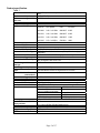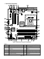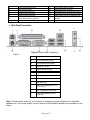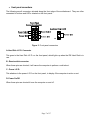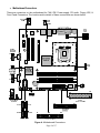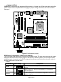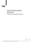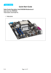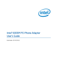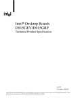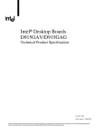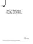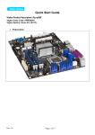
1
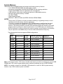
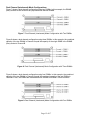
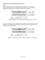
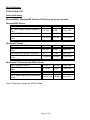
Quick Start Guide
Viglen Product Description: Intel D945GTP Motherboard
Viglen Order Code: PMPTPG01
Viglen System: Genie (S775)
•
Product photo
Page 1 of 17
Product specification.
Table 1.
Motherboard Form Factor
Motherboard chipset
CPU connector type (s370,
slot1 etc)
Number of CPUs supported
Supported CPU types
Supported CPU speeds
Front side bus speed
Number of PCI slots
PCI slot speeds
Number of PCI-E slots
On board video fittedType
Ram size?
Upgradeable?
Onboard audio fitted? Type
Front facing audio header
and type
Audio Upgradeable?
Onboard network fitted?
Type
Number of network
connections?
Upgradeable?
Onboard SCSI fitted? Type
Number of IDE channels
Number of SATA channels
Maximum number of disks
Rear I/O connectors
Memory type
For RIMMs install CRIMM in
empty sockets
Number of memory sockets
Maximum memory support
Supported memory speed
MTBF
Micro ATX (9.60 inches by 9.60 inches [243.84 mm by 243.84
mm])
Intel® 945G Chipset
LGA775 socket
1
Pentium D,P4 and Celeron
CPU No.
CPU speed
FSB
L2 cache
820-840
2.80 - 3.20 GHz
800 MHZ
2 MB
620-670
2.80 - 3.80 GHz
800 MHZ
2 MB
520-570
2.80 - 3.80 GHz
800 MHZ
1 MB
325-345
2.53 - 3.06GHz
533 MHz
1MM
1066MHz, 800MHz and 533MHz
2
33
1 x PCI-E x16 and 1 x PCI-E x1
Intel® Graphics Media Accelerator (GMA) 950 onboard graphics
subsystem
Frame buffer 1MB to 32MB using system memory
Yes
6-channel (5.1) audio subsystem with three analogue audio outputs
using the Sigmatel 9220 audio codec
Yes
Yes via PCI/PCI-Express
Gigabit (10/100/1000 Mbits/sec) LAN subsystem using the
Intel® 82573E/82573V/82574V Gigabit Ethernet Controller
1
Via PCI or PCI-E
No
1
4 (SATA-2) 3Gb/s
6 (2 x IDE 4 x SATA 2) this would require full height ATX case
4 x USB 2
1 x MIC
Note:- 2 x USB 2 front headers 1 x audio out
Total of 8 USB ports possible
1 x serial
1 x audio in
1 x parallel
1 x PS2 mouse
1 x RJ45 LAN
1 x PS2 keyboard
240-pin DDR2 SDRAM DIMM sockets DDR2 400, 533 and 667
N/A
Four 240-pin DDR2 SDRAM DIMM sockets
Support for up to 4 GB of system memory
DDR 2 400, 533 and 667
108,165 hours.
Page 2 of 17
Upgrading and ESD precautions
WARNING
Unplug the system before carrying out the procedures described in this document. Failure
to disconnect power before you open the system can result in personal injury or
equipment damage. Hazardous voltage, current, and energy levels are present in this
product. Power switch terminals can have hazardous Voltages present even when the
power switch is off.
The procedures assume familiarity with the general terminology associated with personal
computers and with the safety practices and regulatory compliance required for using and
modifying electronic equipment.
Do not operate the system with the cover removed. Always replace the cover before
turning on the system.
As the colours of the wires in the mains lead of this computer may not correspond with the coloured
markings identifying the terminals in your plug proceed as follows:
The wire which is coloured green-and-yellow must be connected to the terminal in the plug which is marked
by the letter E or by the safety Earth symbol Ω or coloured green or green-and-yellow.
The wire which is coloured blue must be connected to the terminal which is marked with the letter N or
coloured black.
The wire which is coloured brown must be connected to the terminal which is marked with the letter L or
coloured red.
CAUTION!
The Viglen D945GTP motherboard
and associated components are
sensitive electronic devices. A small
static shock from your body can
cause expensive damage to your
equipment.
Make sure you are earthed and free of static charge before you open the computer case. If you are
unsure about upgrading your computer, return it to Viglen so a qualified engineer can perform the
upgrade.
Page 3 of 17
STEPS TO TAKE TO PREVENT STATIC DISCHARGE:
1. The best way to prevent static discharge is to buy an anti-static strap from your local electrical
shop. While you are wearing the strap and it is earthed, static charge will be harmlessly bled to
ground.
2. Do not remove the component from its anti-static protective packaging until you are about to
install it.
3. Hold boards by the edges - try not to touch components / interface strips etc.
Note:
We recommend that you return your computer to the service department for upgrading. Any work
carried out is fully guaranteed. Upgrades should only be carried out by persons who are familiar
with handling IC's, as incorrect installation will invalidate the guarantee.
Page 4 of 17
• System Board Components
Figure 1 Motherboard Layout & Components
Table 2.
A
B
C
Q
R
S
Power connector (24 way ATX2.2)
Diskette drive connector
Parallel ATE IDE connector
D
E
F
G
Sigmatel 9220 audio codec
PCI Express x1 bus add-in card connectors
Front panel audio connector
PCI Conventional bus add-in card
connectors
Ethernet PLC device
PCI Express x16 bus add-in card connector
Rear chassis fan connector
T
U
V
W
H
I
Back panel connectors
+12V power connector (ATX12V)
X
Y
Battery
Front chassis fan connector
BIOS Setup configuration jumper block
Serial ATA connectors
Auxiliary front panel power LED
connector
Front panel connector
Page 5 of 17
J
K
L
M
N
LGA775 processor socket
Intel 82945G GMCH
Processor fan connector
DIMM Channel A sockets
DIMM Channel B sockets
Z
AA
BB
CC
DD
O
P
SCSI LED connector (optional)
I/O controller
EE
FF
Front panel USB connectors
Chassis intrusion connector
Intel 82801G I/O Controller Hub (ICH7)
SPI Flash device “Firmware Hub (FWH)”
IEEE1394a controller not fitted optional
IEEE1394a connectors not fitted
optional
Speaker
• Back Panel Connectors
Figure 2. Back Panel Connectors.
Table 3.
Item
Description
A
PS/2* mouse port (Green)
B
PS/2 keyboard port (Purple)
C
Serial port A (Teal)
D
Parallel port (Burgundy)
E
VGA port
F
USB ports (two)
G
LAN
H
USB ports (two)
I
Audio line out/Retasking Port D
(Lime Green)
J
Mic in/Retasking Port B (Pink)
K
Audio line in/Retasking Port C
(Light Blue)
Note: The back panel audio line out connector is designed to power headphones or amplified
speakers only. Poor audio quality occurs if passive (non-amplified) speakers are connected to this
output.
Page 6 of 17
• Front panel connections
The following are all connectors situated along the front edge of the motherboard. They are often
connected to buttons and LED’s situated on the front panel.
Figure 3. Front panel connectors
A- Hard Disk L.E.D. Connector
This goes to the Hard Disk L.E.D. on the front panel, which lights up when the IDE Hard Disk is in
use.
B - Reset switch connector
When these pins are shorted, it will cause the computer to perform a cold reboot.
C - Power L.E.D.
This attaches to the power L.E.D on the front panel, to display if the computer is active or not.
D- Power On/Off
When these pins are shorted it turns the computer on and off.
Page 7 of 17
• Motherboard Connectors
There are connectors on the motherboard for FAN, IDE, Power supply, CD audio, Floppy, IDE, &
Front Panel Connectors. The location and/or details of these connections are shown below.
Figure 4. Motherboard Connectors
Page 8 of 17
• Jumper settings
CAUTION Do not move any jumpers with the power on. Always turn off the power and unplug the
power cord from the computer before changing a jumper setting. Otherwise, the board could be
damaged.
Figure 5. Motherboard jumper.
BIOS Setup Configuration Jumper (J7J3) Settings
The 3-pin jumper block determines the BIOS Setup program's mode. The table below describes the jumper
settings for the three modes: normal, configure, and recovery. When the jumper is set to configure mode
and the computer is powered-up, the BIOS compares the processor version and the microcode version in
the BIOS and reports if the two match.
Table 4.
Function/Mode Jumper Setting
Configuration
Normal
1-2
The BIOS uses current configuration information and passwords for
booting.
Configure
2-3
After the POST runs, Setup runs automatically. The maintenance
menu is displayed.
Recovery
None
The BIOS attempts to recover the BIOS configuration. A recovery
diskette is required.
Page 9 of 17
System Memory
The boards have four DIMM sockets and support the following memory features:
• 1.8 V DDR2 SDRAM DIMMs with gold-plated contacts
• Unbuffered, single-sided or double-sided DIMMs with the following restriction:
Double-sided DIMMS with x16 organization are not supported.
• 4 GB maximum total system memory total amount of addressable memory.
• Minimum total system memory: 128 MB
• Non-ECC DIMMs
• Serial Presence Detect
• DDR2 667, DDR2 533 MHz and DDR2 400 MHz SDRAM DIMMs
NOTES
• Remove the PCI Express x16 video card before installing or upgrading memory to avoid
interference with the memory retention mechanism.
• To be fully compliant with all applicable DDR SDRAM memory specifications, the board
should be populated with DIMMs that support the Serial Presence Detect (SPD) data
structure. This allows the BIOS to read the SPD data and program the chipset to accurately
configure memory settings for optimum performance. If non-SPD memory is installed, the
BIOS will attempt to correctly configure the memory settings, but performance and reliability
may be impacted or the DIMMs may not function under the determined frequency.
The following table lists the supported DIMM configurations.
Table 6.
DIMM
SDRAM
Configuration
Capacity
Density
SDRAM Organization
Front-side/Back-side
Number of
SDRAM Devices
128 MB
SS
256 Mbit
16 M x 16/empty
4
256 MB
SS
256 Mbit
32 M x 8/empty
8
256 MB
SS
512 Mbit
32 M x 16/empty
4
512 MB
DS
256 Mbit
32 M x 8/32 M x 8
16
512 MB
SS
512 Mbit
64 M x 8/empty
8
512 MB
SS
1 Gbit
64 M x 16/empty
4
1024 MB
DS
512 Mbit
64 M x 8/64 M x 8
16
1024 MB
SS
1 Gbit
128 M x 8/empty
8
2048 MB
DS
1 Gbit
128 M x 8/128 M x 8
16
Note: In the second column, "DS" refers to double-sided memory modules (containing two rows of DDR
SDRAM) and "SS" refers to single-sided memory modules (containing one row of DDR SDRAM).
NOTE: It is possible to install four 2048 MB (2 GB) modules for a total of 8 GB of system memory,
however, only 4 GB of address space is available.
Page 10 of 17
•
Memory Configurations
The Intel 82915G GMCH supports two types of memory organization:
• Dual channel (Interleaved) mode. This mode offers the highest throughput for real world
applications. Dual channel mode is enabled when the installed memory capacities of both
DIMM channels are equal. Technology and device width can vary from one channel to the
other but the installed memory capacity for each channel must be equal. If different speed
DIMMs are used between channels, the slowest memory timing will be used.
• Single channel (Asymmetric) mode. This mode is equivalent to single channel bandwidth
operation for real world applications. This mode is used when only a single DIMM is installed
or the memory capacities are unequal. Technology and device width can vary from one
channel to the other. If different speed DIMMs are used between channels, the slowest
memory timing will be used.
NOTE
The DIMM0 sockets of both channels are blue. The DIMM1 sockets of both channels are black.
Figure 6. Memory Channel and DIMM Configuration
Page 11 of 17
Dual Channel (Interleaved) Mode Configurations
Figure 7 shows a dual channel configuration using two DIMMs. In this example, the DIMM0
(blue) sockets of both channels are populated with identical DIMMs.
Figure 7. Dual Channel (Interleaved) Mode Configuration with Two DIMMs
Figure 8 shows a dual channel configuration using three DIMMs. In this example, the combined
capacity of the two DIMMs in Channel A equal the capacity of the single DIMM in the DIMM0
(blue) socket of Channel B.
Figure 8. Dual Channel (Interleaved) Mode Configuration with Three DIMMs
Figure 9 shows a dual channel configuration using four DIMMs. In this example, the combined
capacity of the two DIMMs in Channel A equal the combined capacity of the two DIMMs in
Channel B. Also, the DIMMs are matched between DIMM0 and DIMM1 of both channels.
Figure 9. Dual Channel (Interleaved) Mode Configuration with Four DIMMs
Page 12 of 17
Single Channel (Asymmetric) Mode Configurations
NOTE
Dual channel (Interleaved) mode configurations provide the highest memory throughput.
Figure 10 shows a single channel configuration using one DIMM. In this example, only the
DIMM0 (blue) socket of Channel A is populated. Channel B is not populated.
Figure 10. Single Channel (Asymmetric) Mode Configuration with One DIMM
Figure 11 shows a single channel configuration using three DIMMs. In this example, the combined
capacity of the two DIMMs in Channel A does not equal the capacity of the single DIMM in the
DIMM0 (blue) socket of Channel B.
Figure 11. Single Channel (Asymmetric) Mode Configuration with Three DIMMs
Page 13 of 17
Installing & Removing DDR2 SDRAM In-line Memory Modules (DIMMs)
Installing Memory
You can install from 128MB to 4GB of memory in the motherboard DIMM sockets.
The board has four 240-pin DDR2 SDRAM DIMM sockets.
The motherboard supports the following memory features:
•
•
•
240-pin 1.8volt DIMMs with gold-plated contacts.
Non-ECC (64-bit) or ECC (72-bit) memory.
128MB, 256MB, 512MB, 1GB and 2GB (in the future) modules.
When adding memory, follow these guidelines:
• The BIOS detects the size and type of installed memory.
• For ECC operation to become available all installed memory must be ECC and you must
enable the ECC Configuration feature in the BIOS Setup program.
Note:
DDR SDRAM’s must meet the Version 1.0 June 2000 JEDEC Solid State Technology
Association specifications for DDR200/266 SDRAM.
To install DIMMs, follow these steps:
1. Observe the precautions in “Upgrading and ESD precautions”. Turn off the computer and
all peripheral devices.
2. Remove the computer cover and locate the DIMM sockets.
3. Holding the DIMM by the edges, remove it from its antistatic package.
4. Make sure the clips at either end of the socket are pushed away from the socket.
5. Position the DIMM above the socket. Align the two small notches in the bottom edge of
the DIMM with the keys in the socket. Insert the bottom edge of the DIMM into the socket.
6. When the DIMM is seated, push down on the top edge of the DIMM until the retaining clips
at the ends of the socket snap into place. Make sure the clips are firmly in place.
7. Replace the computer cover.
8. If you installed a DIMM with ECC memory, start the computer and use the ECC
Configuration feature in Setup to enable the use of ECC.
Page 14 of 17
Removing Memory
To remove a DIMM, follow these steps:
1.
2.
3.
4.
Observe the precautions in " Upgrading and ESD precautions”.
Turn off all peripheral devices connected to the computer. Turn off the computer.
Remove the computer cover.
Gently spread the retaining clips at each end of the socket. The DIMM pops out of the
socket. Hold the DIMM by the edges, lift it away from the socket, and store it in an
antistatic package.
5. Reinstall and reconnect any parts you removed or disconnected to reach the DIMM
sockets.
Figure. 11. Removing DIMMs
Page 15 of 17
BIOS Initial Release.
NT94510J.86A.1348
Drivers initial release
Windows 98SE, Windows ME, Windows NT4 Drivers are all not supported
Windows 2000 Drivers
Audio: Sigmatel 9220/9221
5.10.4455.0
4.16 MB
10 May 2005
INF: Intel® Chipset Software Installation
Utility
7.0.0.1025
789 KB
27 May 2005
LAN: Intel® PRO Network Connections
10.0
15.7 MB
3 May 2005
Video: Intel® Graphics Media Accelerator
6.14.10.4332 4,491 MB
Driver
16 June 2005
Windows XP Drivers
Audio: Sigmatel 9220/9221
5.10.4487.0
14.1 MB
10 May 2005
INF: Intel® Chipset Software Installation
Utility
7.0.0.1025
789 KB
27 May 2005
LAN: Intel® PRO Network Connections
10.0
15.7 MB
3 May 2005
Video: Intel® Graphics Media Accelerator
6.14.10.4332 4,491 MB
Driver
16 June 2005
Windows XP Professional x64 Edition Drivers
Audio: Sigmatel 9220/9221
5.10.4487.0
14.1 MB
10 May 2005
INF: Intel® Chipset Software Installation
Utility
7.0.0.1025
789 KB
27 May 2005
LAN: Intel® PRO Network Connections
10.0
15.7 MB
3 May 2005
Video: Intel® Graphics Media Accelerator
Driver
14.13.64.4323 4.99 MB
15 Apr 2005
Note:- All the above drivers are PC99 certified.
Page 16 of 17