1
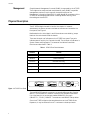
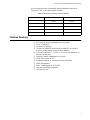
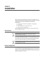
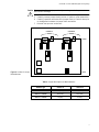
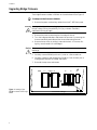
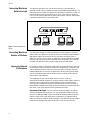
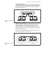
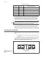
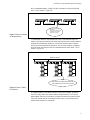
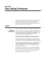
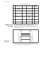
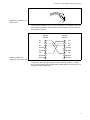
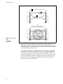
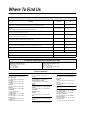
Allied Telesyn CentreCOM AT-3675 Bridge SNMP Manageable User Manual Copyright 1994 Allied Telesyn International, Corp. All rights reserved. No part of this publication may be reproduced without prior written permission from Allied Telesyn International, Corp. Allied Telesyn International, Corp. reserves the right to make changes in specifications and other information contained in this document without prior written notice. The information provided herein is subject to change without notice. In no event shall Allied Telesyn International, Corp. be liable for any incidental, special, indirect, or consequential damages whatsoever, including but not limited to lost profits, arising out of or related to this manual or the information contained herein, even if Allied Telesyn International, Corp. has been advised of, known, or should have known, the possibility of such damages. Trademarks: CentreCOM is a registered trademark of Allied Telesyn International, Corp. Ethernet is a registered trademark of Xerox Corporation. UNIX is a registered trademark of UNIX System Laboratories. Novell and NetWare are registered trademarks of Novell, Inc. Microsoft and MS-DOS are registered trademarks and LAN Manager and Windows for Workgroups are trademarks of Microsoft Corporation. 3Com is a registered trademark of 3Com. PC-NFS is a trademark of Sun Microsystems, Inc. PC/TCP is a registered trademark of FTP Software, Inc. DECnet is a registered trademark of Digital Equipment Corporation. Table Of Contents Electrical Safety and Installation Requirements ..................................................... i Table Of Contents .......................................................................................................... xi Chapter 1 Overview ........................................................................................................................... 1 CentreCOM AT-3675 SNMP-Manageable Bridge ...................................................................................... 1 Performance ............................................................................................................................................... 1 Management ............................................................................................................................................... 2 Physical Description ........................................................................................................................................ 2 Features Summary .......................................................................................................................................... 3 Chapter 2 Installation ....................................................................................................................... 5 Site Selection..................................................................................................................................................... 5 Factory Configuration ..................................................................................................................................... 5 Changing Configuration with Transceivers ................................................................................................. 6 Switching Configuration with Jumpers ........................................................................................................ 6 Upgrading Bridge Firmware ......................................................................................................................... 8 Chapter 3 Operation .......................................................................................................................... 9 Power On ........................................................................................................................................................... 9 Diagnostics ........................................................................................................................................................ 9 Normal Operation............................................................................................................................................. 9 Backup Operation........................................................................................................................................... 10 Application Guidelines................................................................................................................................... 10 Fault Tolerance and Isolation....................................................................................................................... 14 Chapter 4 Troubleshooting ............................................................................................................ 17 Product Code and Serial Number................................................................................................................ 17 Appendix A Data Cabling Techniques ............................................................................................ 19 xi 10BASE-T....................................................................................................................................................... UTP Wiring Specifications.................................................................................................................................. 10BASE-T Point-to-Point Cabling ....................................................................................................... 10BASE-FL/FOIRL Ethernet ................................................................................................................... 10BASE2 (Thin) Ethernet ........................................................................................................................... 10BASE5 (Thick) Ethernet ......................................................................................................................... AUI Drop Cables .................................................................................................................................... 19 19 20 23 23 23 24 Appendix B Glossary ............................................................................................................................25 Appendix C Technical Support Fax Order .....................................................................................31 Incident Summary ......................................................................................................................................... 31 Appendix D CentreCOM AT-3675 Manual Feedback ....................................................................33 Index .................................................................................................................................35 xii Chapter 1 Overview CentreCOM AT-3675 SNMP-Manageable Bridge The CentreCOM AT-3675 SNMP-Manageable Learning Bridge allows you to interconnect two Ethernet sub-networks. Each sub-network may be IEEE 802.3 10BASE2 (thin) Ethernet or 10BASE5 (thick) Ethernet or pre-802.3 Ethernet. Unshielded Twisted Pair (UTP) can also be connected to the bridge through a transceiver. The AT-3675 bridge transparently forwards packets. Since the bridge operates at the Media ACcess (MAC) level, all higher level protocols, such as Transmission Control Protocol (TCP), DECnet™ and NetWare®, are passed unaffected. Performance The four repeater rule does not apply across the bridge. The effective length of a Local Area Network (LAN) can be increased by adding a CentreCOM AT-3675 SNMP-Manageable Learning Bridge. Placing bridges at natural boundaries of the workgroups increases the network performance at each segment by diminishing network traffic. The reliability of a large network can be enhanced by a bridge and allows sub-networks of different media types to be interconnected. The CentreCOM AT-3675 is self-learning, adjusting to reconfiguration of subnets to provide continuous isolation of local traffic. The AT-3675 provides packet filtering at 25,000 Packets Per Second (PPS) and sustained forwarding at 12,500 PPS. Its filter table supports 2,048 MAC-level station addresses. Multiple AT-3675 bridges can be used as backups in case of network failure. The AT-3675 supports the IEEE 802.1 Spanning Tree Protocol (STP), which provides redundancy link management and network loop checking. STP allows backup bridges to provide fault tolerant networks by placing the bridges that form loops into a standby state until an active bridge fails. When failure occurs, the network is reconfigured and any loops are eliminated. This network reconfiguration occurs without impacting the network users or the applications. 1 Overview Management Simple Network Management Protocol (SNMP) is supported by the AT-3675. The bridge can be monitored and manipulated by many SNMP-compatible management stations. Since it supports the second version of the Management Information Base (MIB-II) and Bridge MIB, parameters of the AT-3675 can be managed under SNMP including custom filtering, static forwarding entries and STP. Physical Description The AT-3675 bridge is housed in the slim-line chassis. All network attachments, the power connector and status indicators are located on the front panel. See Figure 1. Media selection for the bridge’s A and B channels are controlled by jumper blocks on the main board inside the chassis. There are three pairs of indicators on the AT-3675 front panel. Two pairs indicate network activity for Channels A and B. The third pair of indicators is System Power and Diagnostics. The names of the indicators and their functions are described in Table 1. Table 1: AT-3675 Front Panel Indicators Indicator Function Transmit A Channel A Transmitting Receive A Channel A Receiving Transmit B Channel B Transmitting Receive B Channel B Receiving Diagnostics Diagnostic Test Status System Power Power is ON CHANNEL B 10 BASE2 10 BASE5 CHANNEL A 10 BASE2 CHANNEL B CHANNEL A SYSTEM ACTIVITY POWER Indicator continually illuminated during self test, then off. Indicator will flash if error detected. 10 BASE5 DIAGNOSTICS TRANSMIT TRANSMIT RECEIVE RECEIVE CentreCOM 3675 TM IEEE 802.3/ETHERNET BRIDGE with SNMP Management SYSTEM POWER Illumination indicates line voltage available. Figure 1: AT-3675 Front Panel The two 10BASE2 network connectors are standard Bayonet Nut Couples (BNCs). The two 10BASE5 network connectors are standard Attachment Unit Interfaces (AUIs) and accept standard 10BASE2, fiber optic (10BASE-FL, FOIRL), 10BASE-T transceivers and 10BASE5 drop cables. Since the AT-3675 bridge has the same dimensions as the AT-3600 Series Repeaters, it may be mounted in an ATI rackmount or desktop chassis. 2 CentreCOM AT-3675 SNMP-Manageable Learning Bridge Not all chassis slots must be populated and populated slots need not be contiguous. Table 2 lists chassis models available. Table 2: Department Concentrators Chassis Available Number of Modules Desktop Model Rackmount Model 1 AT-36E1 AT-36C1 2 AT-36E2 AT-36C2 3 AT-36E3 AT-36C3 4 AT-36E4 AT-36C4 8 AT-36E8 AT-36C8 Features Summary ❑ ❑ ❑ ❑ ❑ ❑ ❑ ❑ ❑ ❑ ❑ ❑ Self -learning SNMP-Manageable Learning Bridge Filter at 25,000 PPS Forward at 12,500 PPS Thinnet (for 10BASE2) and thicknet (for 10BASE5 or pre-802.3 Ethernet) media options on each network segment Fiber optic (10BASE-FL, FOIRL) or UTP with the addition of an optional transceiver(s) Supports 2,048 MAC addresses in filter table IEEE 802.1 revision D STP Standalone, desktop, or rackmount, chassis installation SNMP management MIB-II and Bridge MIB (RFC 1493) One year free software upgrades One year warranty 3 Chapter 2 Installation Before installing the CentreCOM AT-3675 SNMP-Manageable Learning Bridge, check to see that the package contents are complete. If any of the following items are missing or damaged, contact your sales representative. ❑ CentreCOM AT-3675 SNMP-Manageable Learning Bridge ❑ User Manual ❑ Warranty statement and registration cards ❑ Power cord (U.S.A. version only) Save the shipping carton and packing material in case you need to ship or store the bridge in the future. Site Selection Attention Before installing the AT-3675 bridge, read the safety installation ! requirements starting on page i. The AT-3675 bridge should be placed in a cool, well-ventilated area. Air vents are located on each side of the bridge. It is very important that none of the vents is obstructed. Several inches of clearance should be allowed between these vents and any other object, e.g., a wall or other equipment. Caution Failure to follow these ventilation guidelines may result in overheating and ! eventual damage of the bridge. Factory Configuration The AT-3675 bridge is configured at the factory to use the AUI ports on both channels. The AUI connectors (labeled 10BASE5) are active. If you use the bridge in an IEEE 802.3 10BASE5 (or a pre-802.3 Ethernet) environment, no additional configuration is required. 5 Installation Changing Configuration with Transceivers You can attach cable of different media to one or both channels via a transceiver. Table 3 list the transceivers avaiable. Table 3: ATI Micro Transceiver Choices Model Description AT-MX25F Fiber Optic (FOIRL, 10BASE-FL), SMA Connector AT-MX26F Fiber Optic (FOIRL, 10BASE-FL), ST Connector AT-210T/AT-210TS/AT-MX20T UTP (10BASE-T) AT-MX10/AT-MX10S Thin Ethernet (10BASE2) Switching Configuration with Jumpers Each channel can be switched between the BNC connector (labeled 10BASE2) and the AUI connector (labeled 10BASE5). To switch connectors, you move a jumper block inside the bridge chassis. Note Channels A and B are set at the factory to operate with pre-802.3 Ethernet or IEEE 802.3 10BASE5. To determine which port is connected If you are not sure which port is active for a given channel, you can check as follows: 1. Connect one of the channel’s two ports to a cable that is transferring data. 2. If the channel’s Receive indicator flashes, you have selected the active port, if not, the other port is active. To change the jumper block If you need to switch port connections for Channel A and/or Channel B, find the locations of the jumper blocks as shown in Figure 2. Look up the proper jumper block position(s) as listed in Table 4. 1. Remove the power cord and any cables from the AT-3675 front panel. Warning Opening the bridge without unplugging the power cord may expose personnel to high voltage, risking the possibility of injury or death. See safety statements starting on page i. 6 2. Remove the three screws along the front edge of the top. 3. Turn the bridge upside-down and loosen the top cover by removing the three screws along each side and the three screws along the back. 4. Remove the top cover by sliding it towards the back. If the cover fits tightly, use a screwdriver to dislodge it. CentreCOM AT-3675 SNMP-Manageable Learning Bridge Caution The person handling the jumper block(s) must be grounded to prevent electrostatic discharge. ! 5. Carefully remove jumper block(s) with an IC puller or a flat screwdriver. 6. Carefully reposition and reinstall the jumper block(s). Check for bent pins or misalignment between the jumper block and socket. 7. Reinstall the top cover and screws. CHANNEL B CHANNEL A FRONT T4A THICK T4 THIN T2A THICK T2 THIN Figure 2: Location of Jumper Blocks/Sockets REAR Table 4: Jumper Block Options for Media Selection Network Type Channel A Channel B Pre-802.3 Ethernet T4A (Thick) T2A (Thick) IEEE 802.3 10BASE5 T4A (Thick) T2A (Thick) IEEE 802.3 10BASE2 T4 (Thin) T2 (Thin) 7 Installation Upgrading Bridge Firmware The bridge firmware resides in PROMs on the motherboard. See Figure 3. To swap out the firmware PROMs 1. Remove the power cord and any cables from the AT-3675 front panel. Warning Opening the bridge without unplugging the power cord may expose personnel to high voltage, risking the possibility of injury or death. See safety statements starting on page i. 2. Remove the three screws along the front edge of the top. 3. Turn the bridge upside-down and loosen the top cover by removing the three screws along each side and the three screws along the back. 4. Remove the top cover by sliding it towards the back. If the cover fits tightly, use a screwdriver to dislodge it. Caution The person handling the PROM(s) must be grounded to prevent electrostatic ! discharge. 5. Carefully remove PROM(s) with an IC puller or a flat screwdriver. 6. Carefully reposition and reinstall the PROM(s). Check for bent pins or misalignment between the PROM and socket. 7. Reinstall the top cover and screws. ODD B11 EVEN B8 B6 B7 B8 Channel A LEDs Figure 3: Location of the PROMs on the AT-3675 Logic Board 8 Front Panel of Bridge Transmit Receive Chapter 3 Operation This chapter describes the features of the CentreCOM AT-3675 SNMPManageable Learning Bridge and shows the basic operating procedures. It covers how the bridge can be used to overcome common physical limitations and how to employ the bridge in such a way that network performance is improved. Power On When the power is first applied, the green System Power and red Diagnostics indicators are illuminated. The green network Activity indicators are OFF. Diagnostics The AT-3675 bridge executes a comprehensive set of diagnostics when the power is first applied. The red diagnostic LED stays ON and the port’s Receive and Transmit indicators flash as the tests are executed. The Diagnostic indicator turns OFF after successful completion of the tests. If any tests fail, the Diagnostic indicator remains ON. In the latter case, the bridge should be returned for service. Refer to the inside back cover for the ATI location near you. Normal Operation Under normal operation, the green Activity indicators reflect the reception and transmission of data packets, as summarized in Table 5. Table 5: Activity LEDs Indicator Meaning When ON Transmit Channel is Forwarding a Packet Receive Channel is Receiving a Packet 9 Operation Backup Operation The AT-3675 bridge software allows you to establish redundant interconnections between the same two networks. This feature provides backup should the bridge or its network connection fail. The primary bridge and its backup communicate with each other in accordance with the SNMPstandard STP protocol. Because of this signal, the Activity indicators will blink every few seconds, even if there is no other network activity. The STP algorithm can be disabled using a network management package such as SunNet™ Manager or SNMPc. Application Guidelines In planning the placement of bridges, network topology, network length, node count and natural cluster boundaries are all factors you must take into consideration for the best performance. Network Topology A network with bridged sub-networks takes on one of two basic forms. The first is a cascaded network, where a set of sub-networks are connected together by a series of bridges. An example of this configuration is given in Figure 4. A cascaded-bridged network is useful when the number of bridges is small. If many bridges are used, the delay associated with each bridge may accumulate to unacceptable levels between networks at the extremities. CentreCOM 3675 Sub-network A Sub-network B CentreCOM 3675 Sub-network C CentreCOM 3675 Sub-network D Figure 4: A Cascaded Bridged Network The second form used is a tree topology. The simplest configuration of a tree topology is one level deep and is known as a backbone network. Figure 5 shows this type of tree topology. In a backbone configuration, each workgroup has its own network, and there is one network used only for communicating between the workgroups. The advantages of a tree network topology are listed below: ❑ ❑ ❑ 10 There are never more than two bridges between any two sub-networks. The delays introduced by bridges are therefore minimized. As long as the backbone network is operating correctly, any fault within a sub-network has no effect on other sub-networks. Faults are isolated to a single sub-network and are therefore easier to find. CentreCOM AT-3675 SNMP-Manageable Learning Bridge Backbone Network CentreCOM 3675 CentreCOM 3675 Sub-network A Sub-network B CentreCOM 3675 Sub-network C Figure 5: A Backbone Network Mixing Media The AT-3675 bridge can also be used to interconnect network segments that use different media. You may use any medium on either channel. This alone is not a good reason to use a bridge since inexpensive conversion devices are available. However, if you need to install a bridge and need to interconnect different media, the AT-3675 can apply in this case. Figure 6 shows a network that mixes media using a bridge. Thick Ethernet CentreCOM 3675 Figure 6: Example of Mixing Media Thin Ethernet 11 Operation Increasing Maximum Network Length A bridge may be used to link sub-networks serially in the same way a repeater is used. Figure 7 shows this use of the cascaded-bridge topology. The maximum network length only applies to individual sub-networks, so that the overall network length is not bound by any limit. Since there are practical limits on how many bridges can be used in this manner, however, each bridge introduces a small delay in forwarded traffic. CentreCOM 3675 Sub-network A Sub-network B Figure 7: Extending Network Length Exceeding Maximum Number of Stations The maximum number of stations attached to a single network is 1,024. As more stations are added, the number of collisions increases and performance degrades. Bridges can be used to solve this problem. Although there is effectively no limit on the number of nodes that can be attached to a bridged network, there are some practical considerations. Once again, this is due to the delay introduced by each bridge through which a frame passes. Improving Network Performance In one way or another companies are divided into groups. Network users can be considered in terms of natural clusters or workgroups. At one level there may be separate divisions and within a division there are usually teams of people associated with a project or department. When placing new bridges, you can take advantage of natural clustering to provide dramatic network performance improvements. The important thing to realize about natural clusters is that the communication among members of a group produces a much higher volume of network activity than communication between groups. Communication within groups includes inter-personal communication as well as transfer of data between computers. Although groups must be able to communicate with each other, inter-group communication produces less traffic. Placement of Bridges. The key to effective use of bridges is to find the boundaries between workgroups within your organization and to split the network by adding bridges at natural boundaries between different groups. Network traffic within each workgroup is isolated by a bridge and has no effect on the overall network. When computers from different groups need to communicate, bridges allow them to do so as if they were one network. 12 CentreCOM AT-3675 SNMP-Manageable Learning Bridge Simple Bridged Network. In many cases, workgroup boundaries are clearly defined and it is obvious where to place the bridges. This is especially true for small organizations, which will only use one or two bridges or when previously separate networks are being interconnected. Figure 8 below shows this kind of configuration. CentreCOM 3675 Marketing Engineering Figure 8: A Simple Bridged Network Analysis of Large Networks. When a large existing network is broken up into smaller networks, it is useful to perform a thorough analysis of the network traffic patterns. With the aid of a network monitor, you can determine the amount of traffic between nodes throughout the network. Workgroup boundaries (or natural cluster boundaries) exist at the points where the smallest amount of traffic passes. Bridges should always be placed at these points of minimal traffic. For example, consider the network shown in Figure 9. This network of four nodes exhibits traffic patterns listed in Table 6. Node 1 Node 2 Group 1 Node 3 Node 4 Group 2 Figure 9: Analysis of Traffic Patterns 13 Operation Table 6: Traffic Patterns From Node To Node Frames/Second (Average) 1 2 9000 1 3 1000 1 4 1000 2 3 1000 2 4 1000 3 4 9000 In this case there are two clusters. The first contains nodes 1 and 2 and the second contains nodes 3 and 4. Within each cluster, the traffic levels are around 13,000 frames per second, while the traffic between the groups is around 4,000 per second. A bridge could be placed between nodes 2 and 3. Note Placing a bridge between nodes 1 and 2 in this case would make the overall performance worse, because the traffic between these two stations (13,000 frames/second) is higher than the throughput of most bridges. As the network becomes larger it becomes increasingly difficult to find the group boundaries without the assistance of network analysis application programs. In these cases, you may wish to consult network installers who can provide a network analysis service to help you decide where to place bridges. Fault Tolerance and Isolation A single large network has several problems relating to faults. Two are listed below: ❑ If the network fails and coax (thin and thick) is used, all users lose connectivity ❑ Depending on the network size, it may take a long time to find the fault Figure 10 shows the failure of a simple 10BASE2 or 10BASE5 network. When bridges are used, a network becomes much more fault tolerant. This is especially true if a backbone network topology is used. Figure 10: Failure of a Simple Coax Network Without a Bridge 14 Failure here affects all nodes. CentreCOM AT-3675 SNMP-Manageable Learning Bridge With a cascaded network, a fault will split the network into two disjointed parts. This is shown in Figure 11. CentreCOM 3675 Sub-network A CentreCOM 3675 Sub-network B Sub-network C CentreCOM 3675 Sub-network D Failure here partitions the network: 1) Sub-nets A and B are up. 2) Sub-net D is isolated. 3) Sub-net C is down. Figure 11: Failure of a Cascaded- Bridged Network In a backbone network, two possibilities arise. If the backbone fails, the network will be partitioned into as many partitions as there are sub-networks attached to the backbone. However, in the more common case of a failure within one of the attached sub-networks, only that sub-network is affected, while all other sub-networks can still communicate with each other. This is shown in Figure 12. Backbone Network CentreCOM 3675 Sub-network A CentreCOM 3675 Sub-network B CentreCOM 3675 Sub-network C Failure here only affects Sub-network B. Sub-networks A and C are still connected. Figure 12: Failure of a Backbone Network A bridged network is therefore inherently more fault tolerant, providing service to many users even when network components fail. This has the advantage of making it much easier to isolate the cause of the network fault. Since only a small part of the bridged network fails, this provides a much smaller area to search for a problem. 15 Appendix A Data Cabling Techniques Depending on the medium you choose, there are certain wiring practices you should follow to ensure the reliability of communication throughout the network. The following sections detail cabling techniques and port specifications for IEEE 802.3 media. For comprehensive treatment of these topics, refer to the original IEEE specification. 10BASE-T The maximum length for 10BASE-T UTP segments is 100 meters (328 ft.). UTP Wiring Specifications 10BASE-T requires UTP wiring capable of supporting 10 megabit data rates. A serious problem exists concerning identification of modular cable. There are various grades of voice-quality and data-quality cables available. These can appear to be similar externally, although their high-speed data transmission characteristics are radically different. The identification problem is exaggerated by the fact that some suppliers have sold data-quality cables manufactured with voice-quality cabling. If any voice-quality cabling is used in a 10BASE-T network system, data movement is slow, collision-prone or non-existent. To confuse the issue, the Link indicator on the interface will usually indicate a valid link in such a case. For the foregoing reasons, it is absolutely vital that all cabling used with the 10BASE-T connections is of Level 3, 4 or 5. The wire should be 22 to 26 American Wire Gauge (AWG), 100 Ω impedance with 3 to 8 twists per foot. Following these guidelines will help maintain 10 megabit data integrity throughout the wiring system. As a rule of thumb, if a cable type is flat, it is typically untwisted, and will cause problems. If a cable is more or less round in section, it will typically work. “Silver Satin” flat cable is out of specification and should not be used. The six common modular cable specifications and their applicability to 10BASE-T network use are shown in Table 7. 19 Data Cabling Techniques Table 7: UTP Wiring Specifications Cable Description AC Character Specification Twist/ Foot 10BASE-T OK? 1 Unshielded Untwisted N/A CCITT None NO! 2 Individual UTP 100 W ± 30 W RS232 1BASE5 AT&T PDS None NO! 3 Typical Individual UTP 100 W ± 15 W T1, AT&T ISDN 10BASE-T IBM Type 3 3-5 YES 4 Enhanced Individual STP 100 W ± 30 W EIA, TIA 10BASE-T NEMA 5-8 YES 5 Individual STP 100 W ± 30 W EIA, TIA 10BASE-T 8-10 YES IBM Type 1 Individual STP 150 W PCC FT 1 N/A NO! Cable Level 10BASE-T Point-toPoint Cabling Figure 13: 10BASE-T UTP Cabling Hub-to-MAU (Straight-Through) The standard connection when using a repeater is from a Data Communications Equipment (DCE) device, such as a repeater, to a DTE device, such as a workstation NIC. This configuration uses a straight-through cable. See Figure 13. UTP MAU RJ45 PIN UTP HUB RJ45 PIN TD + 1 1 TD + TD - 2 2 TD - RD + 3 3 RD + Not Used 4 4 Not Used Not Used 5 5 Not Used RD - 6 6 RD - Not Used 7 7 Not Used Not Used 8 8 Not Used On an RJ45 connector, it is important to know where pin 1 is so you can count your pins correctly. Figure 14 shows the location of pin 1. 20 CentreCOM AT-3675 SNMP-Manageable Learning Bridge Figure 14: Pin 1 Orientation on an RJ45 Connector Pin 1 Some situations require a DCE-to-DCE connection, for example, when hubs are cascaded. This can be accomplished with a standard cross-over cable, as illustrated in Figure 15. Figure 15: 10BASE-T UTP Cabling Hub-to-Hub (Cross-Over) UTP MAU RJ45 PIN UTP MAU RJ45 PIN TD + 1 1 TD + TD - 2 2 TD - RD + 3 3 RD + Not Used 4 4 Not Used Not Used 5 5 Not Used RD - 6 6 RD - Not Used 7 7 Not Used Not Used 8 8 Not Used In both the cross-over and straight-through instances, the wire is twisted pair. Figure 16 demonstrates usable and unusable cable wire pairings for the straight-through configuration. 21 Data Cabling Techniques A 1 Pair twisted as per Level 3, 4 or 5 cable. RJ45 Pin 1 RJ45 Pin TD+ 1 1 TD+ TD- 2 2 TD- RD+ 3 3 RD+ Not Used 4 4 Not Used Not Used 5 5 Not Used RD- 6 6 RD- Not Used 7 7 Not Used Not Used 8 8 Not Used 1 B This cable will not work for 10BASE-T. Note that 3 and 6 are twisted, but are not a pair. Figure 16: Hub-to-MAU Wiring A.Usable and B. Unusable RJ45 Pin RJ45 Pin TD+ 1 1 TD+ TD- 2 2 TD- RD+ 3 3 RD+ Not Used 4 4 Not Used Not Used 5 5 Not Used RD- 6 6 RD- Not Used 7 7 Not Used Not Used 8 8 Not Used Diagram A is correct because the proper pairs are twisted together. Diagram B is incorrect because the wires for the receive pair, pins 3 and 6, are not twisted together. This could result in excessive common mode noise and an unacceptably high data error rate. If you pair pins incorrectly, for example as shown in Figure 16, Diagram B, your network may have a high data error rate. In a straight-through cable, the transmit pins, 1 and 2, are paired, as are the receive pins, 3 and 6. In a cross-over cable, shown in Figure 17, pins 1 and 2, TD+ and TD-, are paired, as are pins 3 and 6, RD+ and RD-. When pins 1 and 2 are crossed over, they connect to pins 3 and 6 respectively, and pins 3 and 6, when crossed over, connect to pins 1 and 2, respectively. 22 CentreCOM AT-3675 SNMP-Manageable Learning Bridge RJ 45 Pin RJ 45 Pin 1 TD+ 1 1 TD+ TD- 2 2 TD- RD+ 3 3 RD+ 1 Not Used 4 4 Not Used Not Used 5 5 Not Used RD- 6 6 RD- Not Used 7 7 Not Used 8 Not Used 1 Pair twisted as per level 3, 4 or 5 cable Not Used Figure 17: Hub-to-Hub or MAU-to-MAU Wiring 8 10BASE-FL/FOIRL Ethernet The IEEE 802.3 10BASE-FL standard supports up to 2,000 meters (6,560 ft.) of multimode duplex fiber optic cable in a point-to-point link which directly attaches two devices. FL is compatible with FOIRL, but FOIRL supports connections of 1,000 meters (3,280 ft.). Duplex refers to support for fiber optic cable pairs, enabling a two-cable fiber optic connection with transmit mode dedicated to one cable and receive mode on the other. The wide dynamic range of a fiber optic interface allows for an easy installation. When connecting fiber optic cable, the receiving pin (RD) is connected to the transmitting pin (TD) and vice versa. 10BASE2 (Thin) Ethernet When configuring 10BASE2 coax segments, IEEE 802.3 specifications allow 29 or fewer MAUs per cable segment spaced at no less than 0.5 meter (1.64 ft.). The 10BASE2 cable length can not exceed 185 meters (607 ft.) per 10BASE2 cable segment. The worst case propagation delay for a 185 meters (607 ft.) thin Ethernet segment is 950.9 ns. The propagation delay for 10BASE2 Ethernet cable is 5.14 ns/meter. Both ends of the segment must be terminated with a 50 Ω termination with a power rating of 0.5 watts or greater. Earth grounding of the segment shield must take place at only one point on the cable. 10BASE5 (Thick) Ethernet When configuring 10BASE5 coax segments, IEEE 802.3 specifications allow 100 MAU attachments or less, spaced at multiples of 2.5 meters (8.2 ft.) measured accurately from the cable end (50 Ω terminator included). The 10BASE5 cable segment can not exceed 500 meters (1,640 ft.) in length. Worst case “end-to-end” propagation delay of a 10BASE5 coax segment is 23 Data Cabling Techniques 2165 ns. Propagation delay of 10BASE5 Ethernet coax is calculated at 4.33 ns/ meter. Both ends of the segment must be terminated with a 50 Ω termination with a power rating of 0.5 watts or greater. Earth grounding of the segment shield must take place at only one point on the cable. AUI Drop Cables 24 AUI or Drop cables can be no longer than 50 meters (164 ft.) each. Attachments may be made only to the cable ends at the 15-pin D-shell connector. AUI cables may have a maximum 257 ns propagation delay, as used for computing the worst case propagation delay of a cable system. AUI cable propagation delay is approximately 5.13 ns/meter. This cable internally consists of four shielded twisted pair wires with an overall shield and drain wire; a 15-pin D-shell male connector at one end and a 15-pin D-shell female connector at the other end. Cable impedance is nominally 78 Ω. The AUI cable typically connects a transceiver attached to a coaxial segment to a DTE (workstation). Appendix B Glossary 10BASE2—Also called thinnet Ethernet, thinnet or CheaperNet, 10BASE2 is a 10 MHz, baseband, 185 meters (607 ft.) maximum coaxial segment. Cable impedance is 50 Ω. 10BASE5—Also called thick Ethernet, 10BASE5 is a 10 MHz, baseband, 500 meters (1,640 ft.) maximum coaxial segment. The cable is commonly referred to as yellow cable. Cable impedance is 50 Ω. Thick Ethernet cable is typically used as a trunk or backbone path of the network. 10BASE-FL—IEEE 802.3 fiber optic Ethernet. A fiber optic standard that allows up to 2,000 meters (6,560 ft.) of multimode duplex fiber optic cable in a point-to-point link. 10BASE-T—IEEE 802.3 UTP Ethernet. Using low cost Level 3 or better UTP wiring, 100 meters (328 ft.) of point-to-point link segments are possible. Uses RJ45 connectors and sometimes 50-pin AMP connectors to a patch panel. Runs at 10 MHz. 50-PIN TELCO (RJ21)—This connector is very common in 10BASE-T wiring. As opposed to the RJ45 connector, the 50-pin Telco connector concentrates up to 12 UTP connections onto one connection. This concentration of UTP ports is then broken out for connection to a punch-down block inside a building’s wiring closet. 50-pin Telco connections provide a very clean, uncluttered interface to the building’s wiring. AT-ADAPT-2— A harmonica-style adapter that allows direct conversion from a 50-pin Telco connector to RJ45 receptacles. ATTACHMENT UNIT INTERFACE (AUI)—This is the cable connection from a MAU (transceiver) to a DTE (typically a workstation) consisting of a 15-conductor twisted pair cable of 50 meters (164 ft.) maximum length. BACKUP MODULE— A repeater that behaves as the management module when the Master fails in a department concentrator. BASEBAND COAXIAL SYSTEM—A system whereby information is directly encoded and impressed on the coaxial transmission medium. At any point on the medium, only one information signal at a time can be present without disruption. 25 Glossary BAYONET NUT COUPLE (BNC) CONNECTOR—A 10BASE2 thin coax connector with push-on BNC locking lug that quickly locks into place with a half twist. BIT RATE (BR)—This is the rate of data throughput on the medium in bits per second. Ethernet specifies 10 million bits per second. BRANCH CABLE—The AUI cable interconnecting the DTE and MAU system components also known as a Drop cable. BIT TIME—The duration of one bit symbol (1/BR). Ethernet specifies a bit time of 100 ns. CARRIER SENSE—In a LAN, an ongoing activity of a data station to detect whether another station is transmitting. CARRIER SENSE MULTIPLE ACCESS with COLLISION DETECT (CSMA/CD)—This is the access method employed by IEEE 802.3 LAN transceivers, by which multiple stations compete for use of the transmission medium (coax cable) for data packet transmission, and provides for a level of error detection should that transmission be corrupted or impeded by contention for the transmission medium. COAX SEGMENT—A segment of Ethernet cable that contains MAU. COAXIAL CABLE—A two conductor (center conductor, shield system), concentric, constant impedance transmission line used as the trunk medium in the baseband system. COAXIAL CABLE SEGMENT—A length of coaxial cable sections and coaxial connectors, and terminated at each end in its characteristic impedance. COLLISION—An unwanted condition that results from concurrent transmissions on the physical medium. COLLISION PRESENCE—A signal provided by the PLS to the PMA sublayer (within the physical layer) to indicate that multiple stations are contending for access to the transmission medium. COMPATIBILITY INTERFACE—The MDI coaxial cable interface and the AUI branch cable interface, the two points at which hardware compatibility is defined to allow connection of independently designed and manufactured components to the baseband transmission system. CROSS-OVER—Wiring is used when connecting a 10BASE-T MAU to another 10BASE-T MAU or a 10BASE-T hub to another 10BASE-T hub. For example, one 10BASE-T MAU would have the TD pair on the same pins as another 10BASE-T MAU. If pins were wired straight, there would be two transmitters on one pair with no receiver. Therefore, the cross-over cable crosses the TD pair with the RD pair of UTP cable connecting the TD pins on one end to the RD pins at the other end. D-SUB CONNECTOR—The AUI cable uses 15-pin D-sub connectors. “D” refers to the shape of the connector shell. Also called miniature D, DB15 or DIX connectors. 26 CentreCOM AT-3675 SNMP-Managable Learning Bridge DATA COMMUNICATION EQUIPMENT (DCE)—In RS232 specification a unit, such as a modem, for connecting a DTE to other equipment. A repeater connected to a terminal or workstation for OMEGA LOCAL management use is wired as a DCE. DATA TERMINAL EQUIPMENT (DTE)—In RS232 specification a unit typically at the end of a segment. The DTE could be an Ethernet workstation, repeater or bridge. DEPARTMENT CONCENTRATOR—Hub which provides a large number of workstation connections. The term, department concentrator, refers to multiple repeaters housed in an Allied Telesis chassis. See Hub/ Repeater, Repeater. DIX CONNECTOR—See D-Sub Connector FOIRL — A fiber optic standard that allows up to 1,000 meters (3,280 ft.) of multimode duplex fiber optic cable in a point-to-point link. HARMONICA ADAPTER—This adapter provides a simple way to convert the 50-pin Telco connection to RJ45 connections. HEARTBEAT—See SQE HOT SWAPPING— The process of replacing a hub module without bringing down the network. This process occurs by sliding an active module into a fully powered up concentrator, replacing a failed module. HUB to HUB WIRING—See Hub to MAU Wiring HUB to MAU WIRING—UTP cables for 10BASE-T hub-to-MAU or Network Interface Controller (NIC) cards are wired straight-through. An RJ45 receptacle at the hub would wire pin to pin to the RJ45 receptacle at the MAU. HUB/REPEATER—A hub is a central signal distributor. It is used in a wiring topology consisting of several point-to-point segments originating from a central point. The term hub is often used interchangeably with the term repeater. Multiport 10BASE-T, 10BASE2 and fiber optic (10BASE-FL, FOIRL) repeaters are considered hubs. In this manual, the term hub is used generic, in discussions of software which does not distinguish between standalone repeaters and department concentrators. See Repeater. HOUSE WIRING—House wiring is the existing wiring inside a building. This wiring generally originates from one or more wiring closets such as a telephone room. Some older buildings may have wiring unsuitable for 10 Megabit data rates. In these circumstances, it is recommended that the wiring is tested with a 10BASE-T signal/wire tester. IMPEDANCE—An electrical characteristic of a circuit dealing with the combination of the AC and DC resistance and the appearance of that resistance to attached circuits. 27 Glossary JABBER LOCK-UP—The MAU’s ability to automatically inhibit the transmit data from reaching the medium if the transmit data time exceeds a specified duration. This duration is in the range of 20 ms to 150 ms. Jabber lock-up protects the medium from being overrun with data packets from a possibly defective device. JAM—This is a term used to describe the collision reinforcement signal output by the repeater to all ports. The jam signal consists of 96 bits of alternating 1s and 0s. The purpose is to extend a collision sufficiently so that all devices cease transmitting. JITTER—The fluctuation of the data packet in respect to a standard clock cycle. Jitter is undesirable and must be minimized. LINK SEGMENT—The link segment of coaxial cable is a segment which has no MAU devices but links two LAN devices together such as repeaters. LINK TEST—In 10BASE-T Ethernet there is a link test function that validates the UTP link. This consists of a pulse transmitted from point A on one pair and validated at point B. Point B also transmits a pulse on the second pair to be validated by point A. These pulses occur during media idle states (in between packets). MANAGED MODULE— An intelligent repeater in a department concentrator chassis that makes management data available to the Master. MANAGEMENT AGENT—Software that is used to view hub activity and set hub variables. MASTER—A repeater in the top-most position in a department concentrator chassis that contains and downloads the management agent software to Backup and Slaves. The Master contains the only active image of the management agent and controls the management functions of the Backup and Slaves. MAU—See Medium Attachment Unit MAU-to-MAU, HUB-to-HUB WIRING—10BASE-T MAU-to-MAU or hub-to-hub wiring generally requires a cross-over cable located somewhere along the UTP cable run. This may commonly occur at the punch-down block or between the RJ45 wall receptacle and the workstation. MAU/TRANSCEIVER—An Ethernet transceiver is a MAU. A 10BASE-T MAU interfaces the UTP media to an AUI port on a workstation, repeater, bridge, or other Ethernet devices. MDI/MDI-X—See Medium Dependent Interface MEDIUM ATTACHMENT UNIT (MAU)—In a LAN, a device used in a data station to couple the DTE to the transmission medium. MEDIUM DEPENDENT INTERFACE (MDI)—The mechanical and electrical interface between the trunk cable medium and the MAU. MDI-X is another version of the interface that enables like devices to connect, using different pin-outs, avoiding conflicts that occur when receiving and transmitting packets use the same pin-out. 28 CentreCOM AT-3675 SNMP-Managable Learning Bridge MODULE—A single repeater when it is mounted with other repeaters in an AT-36Cx or AT-36Ex department contentrator chassis. N-SERIES—A barrel shaped, threaded connector used on 10BASE5 (thick Ethernet) coaxial cable. PATCH PANEL—A 10BASE-T patch panel may be between a punch-down block and UTP workstation. The patch panel generally has a female RJ45 connector on the front for each workstation and a Telco (RJ21) connector on the back, which are wired to a punch-down block. This provides a convenient way for the installer or network manager to connect the hub 10BASE-T ports into the desired building locations. PHYSICAL MEDIUM ATTACHMENT (PMA)—The portion of the MAU that contains the functional circuitry. PHYSICAL SIGNALING (PLS)—That portion of the physical layer contained within the DTE that provides the logical and functional coupling between MAU and data link layers. POLARITY CORRECTION—Many 10BASE-T UTP ports have a Polarity Correction function. If the UTP wiring has RD- and RD+ inadvertently crossed, the polarity correction function will sample the signal and electrically swap the wires. If the TD- and TD+ wires are crossed, the correction would occur at the MAU on the other end of the UTP link. This occurs within a single pair and should not be confused with the cross-over cable. PROPAGATION DELAY—The time it takes a signal to travel from the input of a system component to the output. Usually measured in nanoseconds. IEEE 802.3 has specific propagation delay maximums for computing propagation budgets when designing a LAN. Cable length plays a major role in propagation delay. [i.e, a 50 meters (164 ft.) AUI cable has a maximum allowable propagation delay of 257 ns.] The propagation delay of cable is dependent on length and velocity factor of the cable type. There are also propagation delays associated with electronics attached to the system. PUNCH-DOWN BLOCK—The punch-down block is the wiring panel where the house wiring from the building’s offices terminates. This is where many 10BASE-T hubs would be located. Wiring installers use a special punch-down tool to insert the UTP wire for data and voice applications. REPEATER—A device used to extend the length, topology, or interconnectivity of the physical medium beyond that imposed by a single segment, up to the maximum allowable end-to-end trunk transmission line length. Repeaters perform the basic actions of restoring signal amplitude, wave form and timing applied to normal data and collision signals. In the manual, “repeater” refers to a standalone unit or a module in an AT-36Cx or AT-36Ex department concentrator chassis. For the purposes of network topology analysis, either a standalone repeater or a fully populated department concentrator counts as just one repeater. RJ45—This connector is a 10BASE-T standard for connecting UTP cabling. They are inexpensive and easy to install onto UTP cable. SIGNAL QUALITY ERROR (SQE)—Also referred to as Collision or Collision Presence. This occurs when two devices attempt to transmit at the same time which is an illegal condition. 29 Glossary SIMPLE NETWORK MANAGEMENT PROTOCOL (SNMP)— SNMP is a TCP/IP protocol that generally uses the User Datagram Protocol (UDP) to exchange messages between a management information base and a management client residing on a network. Since SNMP does not rely on the underlying communication protocols, it can be made available over other protocols, such as XNS or DECNET. SLAVE— A repeater that behaves as a “dumb” module managed by a Master in a department concentrator chassis. Slaves operating standalone perform only simple regeneration and retiming tasks associated with repeating and are not manageable. SQE TEST—Commonly referred to as Heartbeat, is a special 802.3 signal sent by the MAU to the DTE to test the collision detection function. Some DTE want SQE and others do not. Repeaters do not want SQE Test. STANDALONE—Repeater operating as a hub on its own; i.e., not a module among other modules in a department concentrator chassis. STRAIGHT-THROUGH—A type of wiring connection where the pins of one connector connect to the same pins of another connector. For example, pin 1 of one connector connects to pin 1 of another connector. TCP/IP PROTOCOLS—A set of protocols for inter-computer communication, including network level (Internet Protocol), transport level (Transmission Control Protocol or TCP), and application level protocols (for example, Telnet terminal emulation). TCP/IP has been used for many years in two country-wide networks, the ARPANET and MILNET. Recently, TCP/IP has become very popular with users of a variety of multi-user computer systems and engineering workstations. Most UNIX computers use TCP/IP over Ethernet as the main inter-computer networking technology. TCP/IP is also popular among PC users, particularly as a means of communication with large multi-user computers. TELCO CONNECTOR—A 50-pin receptacle that plugs into the front of the hub, enabling cables from external devices to connect to the hub. THICK ETHERNET—See 10BASE5 THIN ETHERNET—See 10BASE2 TRUNK CABLE—The trunk coaxial cable system. UNMANAGED MODULE—A repeater that behaves as a “dumb” repeater in a department concentrator chassis (i.e., without a Master). It performs simple repeating tasks like packet retiming and regeneration, but is not managed. UNSHIELDED TWISTED PAIR (UTP)—A cable used in 10BASE-T wiring that consists of at least two twisted pairs of 22 to 26 AWG wire. The pairs should have at least 3 twists per foot and have an impedance of 100 Ω. Level 3 and Level 4 UTP cable generally fits these criteria. 30 Appendix C Technical Support Fax Order Name _______________________________ ____________________________________ Company ________________________________________________________________ Address _________________________________________________________________ City ____________________State/Province____________ Zip/PostalCode __________ Country _________________ Phone __________________Fax_____________________ Incident Summary Model number of ATI product I am using ______________________________________ Firmware release of ATI product _____________________________________________ Other network software products I am using (e.g., network managers) ________________________________________________________________________ Brief summary of problem __________________________________________________ ________________________________________________________________________ Conditions (List the steps that led up to the problem.) ___________________________ ________________________________________________________________________ ________________________________________________________________________ ________________________________________________________________________ Detailed description (Please use separate sheet) Please also fax printouts of relevant files such as batch files and configuration files. Technical Support Fax Numbers: Asia (+65) 383-2079 Singapore, Taiwan, Thailand, Malaysia, Indonesia, Korea, Hong Kong, Philippines, China, India France France, Belgium, Luxembourg, Holland, Italy, Spain, Australia, New Zealand, Greece, Middle East, Africa, South America (+33) 1-69-28-37-49 Germany Germany, Switzerland, Austria, Eastern Europe (+49) 30-435-70-650 North America United States, Canada, Mexico (206) 481-3790 United Kingdom United Kingdom, Denmark, Norway, Sweden, Finland, Iceland (+44) 1-865-390-002 31 Appendix D CentreCOM AT-3675 Manual Feedback We would like you to tell us what additional information you would like to see discussed in the manual. If there are topics you would like information on that were not covered in the manual, please photocopy this page, answer the questions and fax or mail this form to ATI The mailing address and fax number are at the bottom of the page. Your comments are valuable when we plan future revisions of the manual. On a scale of 1 to 10 (10 being most important), rate the importance of the following topics in this manual: Hardware Installation Diagnostics SNMP Data Cabling Techniques Cabling _______ _______ _______ _______ _______ Channel Configuration MIB Troubleshooting Reading the LEDs Software Downloading ______ ______ ______ ______ ______ I found the following the most valuable ______________________________ _________________________________________________________________ _________________________________________________________________ I would like the following more developed ___________________________ _________________________________________________________________ _________________________________________________________________ I would find the manual more useful if _______________________________ _________________________________________________________________ _________________________________________________________________ Please fax or mail your feedback. Fax to 1-206-481-3790. Or mail to: Allied Telesyn Technical Publications Department 19015 North Creek Parkway, Suite 200 Bothell, WA 98011 USA 33 Where To Find Us For Technical Support or Service Location Phone Fax North America United States, Canada, Mexico, Central America, South America, Australia, New Zealand 1 (800) 428-4835 1 (206) 481-3790 France France, Belgium, Luxembourg, The Netherlands, Middle East, Africa (+33) 1-69-28-16-17 (+33) 1-69-28-37-49 Germany Germany, Switzerland, Austria, Eastern Europe (+01) 30-83-56-66 (+49) 30-435-70-650 Italy Italy, Spain, Portugal, Greece, Turkey, Israel (+39) 2-38093-444 (+39) 2-38093-448 United Kingdom United Kingdom, Denmark, Norway, Sweden, Finland, Iceland (+0) 800-20-40-40 (+44) 1-865-390-002 Japan (+81) 3-3443-5640 (+81) 3-3443-2443 Asia Singapore, Taiwan, Thailand, Malaysia, Indonesia, Korea, Philippines, China, India (+65) 383-2050 (+65) 383-2079 Hong Kong (+852) 2-529-4111 (+852) 2 529-7661 Technical Bulletin Board Service 1 (206) 483-7979 CompuServe Go ALLIED World Wide Web http://www.alliedtelesyn.com For Information Regarding Allied Telesyn International Corp. Allied Telesyn International Corp. 19015 North Creek Parkway Suite 200 Bothell, WA 98011 TEL: 1 (206) 487-8880 FAX: 1 (206) 489-9191 Allied Telesyn International Corp. 950 Kifer Road Sunnyvale, CA 94086 Tel: 1 (800) 424-4284 (USA and Canada) Fax: 1 (408) 736-0100 For Sales Information United States Lilburn, GA Tel: (404) 717-0290, Fax: (404) 717-0806 Salt Lake City, UT Tel: (801) 350-9130, Fax: (801) 350-9051 Vienna, VA Tel: (703) 506-0196, Fax: (703) 506-1986 Chicago, IL Tel: (708) 406-8431, Fax: (708) 406-8462 Austin, TX Tel: (512) 502-3087, Fax: (512) 794-9326 Dallas, TX Tel: (214) 446-9873, Fax: (214) 446-8555 Reading, MA Tel & Fax: (617) 944-3492 Los Angeles, CA Tel: (310) 412-8684, Fax: (310) 412-8685 Costa Mesa, CA Tel: (714) 432-6424, Fax: (714) 432-6546 San Diego, CA Tel: (619) 279-3896, Fax: (619) 279-3897 Clearwater, FL Tel: (813) 726-0022, Fax: (813) 726-0234 Tunnersville, NJ Tel: (609) 438-1070, Fax: (609) 468--1201 Canada Mississauga, Ontario Tel: (905) 803-8626, Fax: (905) 279-0050 Richmond, British Columbia Tel: (604) 244-0678, Fax: (604) 270-3644 Germany Berlin Tel: (+49) 30-435-9000, Fax: (+49) 30-435-70650 Freising Tel: (+49) 8161-62-002, Fax: (+49) 8161-68-374 Lothar Bahn The Netherlands Schiphol Tel: (+31) 20-654-0111, Fax: (+31) 20-654-0270 Italy Milano Tel: (+39) 2-38093-444, Fax: (+39) 2-38093-448 England Abingdon, Oxon Tel: (+1) 44-865-390001, Fax: (+1) 44-865-390002 France Les Ulis Tel: (+33) 1-69-28-16-17, Fax: (+33) 1-69-28-37-49 Hong Kong Kowloon Tel: (+852) 2-393-0101, Fax: (+852) 2-397-7979 Wanchai Tel: (+852) 2-529-4111, Fax: (+852) 2-529-7661 Singapore Tel: (+65) 383-3832, Fax: (+65) 383-3830 Japan Shinagawa-ku, Tokyo Tel: (+81) 3-3443-5640, Fax: (+81) 3-3443-2443 Yodogawa-ku, Osaka Tel: (+81) 6-391-6310, Fax: (+81) 6-391-6325 Fujisawa-shi, Kanagawa Tel: (+81) 466-88-8510, Fax: (+81) 466-88-8515 Machida-shi, Tokyo Tel: (+81) 427-21-8141, Fax: (+81) 427-21-8848 Nagoya-shi, Aichi Tel: (+81) 52-223-3791, Fax: (+81) 52-223-3736