1
©2011, Videolarm, Inc. All Rights Reserved
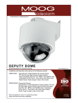
DeputyDome™
Bullet-Resistant IP Camera Housing
www.videolarm.com
Installation and Operation Instructions for the following models:
DDW10CN2 DeputyDome™, Bullet-Resistant IP Camera System, PTZ and 26x Day/ Night Camera System features Heavy-Duty Metal Gear Pan/ Tilt. MPEG-4 and MJPEG video compression format, full D1. Clear dome, with 24Vac input, heater/ blower Tough enough to stop a 9mm bullet
PDDW10CN2 (Pressurized Version)
DeputyDome™, Bullet-Resistant IP Camera System, PTZ and 26x Day/ Night Camera System features Heavy-Duty Metal Gear Pan/ Tilt. MPEG-4 and MJPEG video compression format, full D1. Clear dome, with 24Vac input, heater/blower Tough enough to stop a 9mm bullet
B e f o r e a t t e m p t i n g t o c o n n e c t o r o p e r a t e t h i s p r o d u c t , p l e a s e r e a d t h e s e i n s t r u c t i o n s c o m p l e t e l y.
-1-
81-IN5387
12-13-2011
IMPORTANT SAFEGUARDS
1
Read these instructions.
2
Keep these instructions.
3
Heed all warnings
4
Follow all instructions.
5
Do not use this apparatus near water.
6
Clean only with damp cloth.
7
SAFETY PRECAUTIONS
CAUTION
RISK OF ELECTRIC SHOCK
DO NOT OPEN
CAUTION: TO REDUCE THE RISK OF
ELECTRIC SHOCK, DO NOT REMOVE
COVER ( OR BACK). NO USER- SERVICEABLE PARTS INSIDE. REFER SEVICING
TO QUALIFIED SERVICE PERSONNEL.
Do not block any of the ventilation openings. Install in accordance with the
manufacturers instructions.
8
9
Cable Runs- All cable runs must be within permissible distance.
Mounting - This unit must be properly and securely mounted to a supporting
structure capable of sustaining the weight of the unit.
Accordingly:
a. The installation should be made by a qualified installer.
b. The installation should be in compliance with local codes.
c. Care should be exercised to select suitable hardware to install the unit, taking into
account both the composition of the mounting surface and the weight of the unit.
10 Do not install near any heat sources such as radiators, heat registers, stoves, or other
apparatus ( including amplifiers) that produce heat.
11 Do not defeat the safety purpose of the polarized or grounding-type plug. A
polarized plug has two blades with one wider than the other. A grounding type
plug has two blades and a third grounding prong. The wide blade or the third
prong are provided for your safety. When the provided plug does not fit into your
outlet, consult an electrician for replacement of the obsolete outlet.
12 Protect the power cord from being walked on or pinched particularly at plugs,
convenience receptacles, and the point where they exit from the apparatus.
13 Only use attachment/ accessories specified by the manufacturer.
14 Use only with a cart, stand, tripod, bracket, or table specified by the manufacturer,
or sold with the apparatus. When a cart is used, use caution when moving the cart/
apparatus combination to avoid injury from tip-over.
15 Unplug this apparatus during lighting storms or when unused for long periods of time.
16 Refer all servicing to qualified service personnel. Servicing is required when the
apparatus has been damaged in any way, such as power-supply cord or plug is
damaged, liquid has been spilled of objects have fallen into the apparatus, the
The lightning flash with an arrowhead symbol,
within an equilateral triangle, is intended to
alert the user to the presence of non-insulated
“dangerous voltage” within the product’s
enclosure that may be of sufficient magnitude
to constitute a risk to persons.
Este símbolo se piensa para alertar al usuario a la presencia
del “voltaje peligroso no-aisIado” dentro del recinto de los
productos que puede ser un riesgo de choque eléctrico.
Ce symbole est prévu pour alerter I’utilisateur à la presence
“de la tension dangereuse” non-isolée dans la clôture de
produits qui peut être un risque de choc électrique.
Dieses Symbol soll den Benutzer zum Vorhandensein der
nicht-lsolier “Gefährdungsspannung” innerhalb der
Produkteinschließung alarmieren die eine Gefahr des
elektrischen Schlages sein kann.
Este símbolo é pretendido alertar o usuário à presença “di
tensão perigosa non-isolada” dentro do cerco dos produtos
que pode ser um risco de choque elétrico.
Questo simbolo è inteso per avvertire I’utente alla presenza
“di tensione pericolosa” non-isolata all’interno della
recinzione dei prodotti che può essere un rischio di scossa
elettrica.
apparatus has been exposed to rain or moisture, does not operate normally, or
has been dropped.
Be sure to periodically examine the unit and the supporting structure to make sure that the integrity
of the installation is intact. Failure to comply with the foregoing could result in the unit separating
from the support structure and falling, with resultant damages or injury to anyone or anything struck
by the falling unit.
UNPACKING
Unpack carefully. Electronic components can be
damaged if improperly handled or dropped. If an item
appears to have been damaged in shipment, replace
it properly in its carton and notify the shipper.
Be sure to save:
1 The shipping carton and packaging material.
They are the safest material in which to make future
shipments of the equipment.
2 These Installation and Operating Instructions.
SERVICE
If technical support or service is needed, contact us at
the following number:
TECHNICAL SUPPORT
AVAILABLE 24 HOURS
1 - 800 - 554 -1124
-2-
The exclamation point within an equilateral
triangle is intended to alert the user to
presence of important operating and
maintenance (servicing) instructions in the
literature accompanying the appliance.
Este símbolo del punto del exclamation se piensa para
alertar al usuario a la presencia de instrucciones importantes
en la literatura que acompaña la aplicación.
Ce symbole de point d’exclamation est prévu pour alerter
l’utilisateur à la presence des instructions importantes dans
la littérature accompagnant l’appareil.
Dieses Ausruf Punktsymbol soll den Benutzer zum
Vorhandensein de wichtigen Anweisungen in der Literatur
alarmieren, die das Gerät begleitet.
Este símbolo do ponto do exclamation é pretendido alertar o
usuário à presença de instruções importantes na literatura
que acompanha o dispositivo.
Questo simbolo del punto del exclamaton è inteso per
avvertire l’utente alla presenza delle istruzioni importanti nella
letteratura che accompagna l'apparecchio.
Limited Warranty for Moog Videolarm Products
Moog Videolarm warrants these products to be free from defects in material or workmanship as follows:
PRODUCT CATEGORY
PARTS \ LABOR
All Enclosures and Electronics*
Five
Poles/PolEvators™/CamEvator
Three (3) Years
Warrior Series™/Q-View™/IR Illuminators
Five
(5) Years
SView Series™
Five
(5) Years **6 months if used in auto scan/tour operation
Controllers
Five
(5) Years
Power Supplies
Five
(5) Years
EcoKit
Three (3) Years
Accessory Brackets
Five
Liberty Dome
Three (3) Years
*DeputyDome™, NiteTrac™, Igloo Dome, PurgeDome™
Three (3) Years **6 months if used in auto scan/tour operation
(5) Years
(5) Years
During the labor warranty period, to repair the Product, Purchaser will either return the defective product, freight prepaid, or deliver it to Moog Videolarm
Inc. Decatur GA. The Product to be repaired is to be returned in either its original carton or a similar package affording an equal degree of protection with
a RMA # (Return Materials Authorization number) displayed on the outer box or packing slip. To obtain a RMA# you must contact our Technical Support
Team at 800.554.1124, extension 101. Moog Videolarm will return the repaired Product freight prepaid to Purchaser. Moog Videolarm is not obligated to
provide Purchaser with a substitute unit during the warranty period or at any time. After the applicable warranty period, Purchaser must pay all labor and/or
parts charges.
The limited warranty stated in these product instructions is subject to all of the following terms and conditions.
TERMS AND CONDITIONS
1. NOTIFICATION OF CLAIMS: WARRANTY SERVICE: If Purchaser believes that the Product is defective in material or workmanship, then written notice with an
explanation of the claim shall be given promptly by Purchaser to Moog Videolarm. All claims for warranty service must be made within the warranty period.
If after investigation Moog Videolarm determines the reported problem was not covered by the warranty, Purchaser shall pay Moog Videolarm for the cost of
investigating the problem at its then prevailing per incident billable rate. No repair or replacement of any Product or part thereof shall extend the warranty period
of the entire Product. The specific warranty on the repaired part only shall be in effect for a period of ninety (90) days following the repair or replacement of that
part or the remaining period of the Product parts warranty, whichever is greater.
2. EXCLUSIVE REMEDY: ACCEPTANCE: Purchaser’s exclusive remedy and Moog Videolarm’s sole obligation is to supply (or pay for) all labor necessary to repair any
Product found to be defective within the warranty period and to supply, at no extra charge, new or rebuilt replacements for defective parts.
3. EXCEPTIONS TO LIMITED WARRANTY: Moog Videolarm shall have no liability or obligation to Purchaser with respect to any Product requiring service during the
warranty period which is subjected to any of the following: abuse, improper use, negligence, accident, lightning damage or other acts of God (i.e., hurricanes,
earthquakes), modification, failure of the end-user to follow the directions outlined in the product instructions, failure of the end-user to follow the maintenance
procedures recommended by the International Security Industry Organization, written in product instructions, or recommended in the service manual for the
Product. Furthermore, Moog Videolarm shall have no liability where a schedule is specified for regular replacement or maintenance or cleaning of certain parts
(based on usage) and the end-user has failed to follow such schedule; attempted repair by non-qualified personnel; operation of the Product outside of the
published environmental and electrical parameters, or if such Product’s original identification (trademark, serial number) markings have been defaced, altered,
or removed. Moog Videolarm excludes from warranty coverage Products sold AS IS and/or WITH ALL FAULTS and excludes used Products which have not
been sold by Moog Videolarm to the Purchaser. All software and accompanying documentation furnished with, or as part of the Product is furnished “AS IS”
(i.e., without any warranty of any kind), except where expressly provided otherwise in any documentation or license agreement furnished with the Product. Any
cost associated with removal of defective product and installation of replacement product is not included in this warranty.
4. PROOF OF PURCHASE: The Purchaser’s dated bill of sale must be retained as evidence of the date of purchase and to establish warranty eligibility.
DISCLAIMER OF WARRANTY
EXCEPT FOR THE FOREGOING WARRANTIES, Moog Videolarm HEREBY DISCLAIMS AND EXCLUDES ALL OTHER WARRANTIES, EXPRESS OR IMPLIED,
INCLUDING, BUT NOT LIMITED TO ANY AND/OR ALL IMPLIED WARRANTIES OF MERCHANTABILITY, FITNESS FOR A PARTICULAR PURPOSE AND/OR
ANY WARRANTY WITH REGARD TO ANY CLAIM OF INFRINGEMENT THAT MAY BE PROVIDED IN SECTION 2-312(3) OF THE UNIFORM COMMERCIAL
CODE AND/OR IN ANY OTHER COMPARABLE STATE STATUTE. Moog Videolarm HEREBY DISCLAIMS ANY REPRESENTATIONS OR WARRANTY THAT
THE PRODUCT IS COMPATIBLE WITH ANY COMBINATION OF NON-Moog Videolarm PRODUCTS OR NON-Moog Videolarm RECOMMENDED PRODUCTS
PURCHASER MAY CHOOSE TO CONNECT TO THE PRODUCT.
LIMITATION OF LIABILITY
THE LIABILITY OF Moog Videolarm, IF ANY, AND PURCHASER’S SOLE AND EXCLUSIVE REMEDY FOR DAMAGES FOR ANY CLAIM OF ANY KIND
WHATSOEVER, REGARDLESS OF THE LEGAL THEORY AND WHETHER ARISING IN TORT OR CONTRACT, SHALL NOT BE GREATER THAN THE ACTUAL
PURCHASE PRICE OF THE PRODUCT WITH RESPECT TO WHICH SUCH CLAIM IS MADE. IN NO EVENT SHALL Moog Videolarm BE LIABLE TO PURCHASER
FOR ANY SPECIAL, INDIRECT, INCIDENTAL, OR CONSEQUENTIAL DAMAGES OF ANY KIND INCLUDING, BUT NOT LIMITED TO, COMPENSATION,
REIMBURSEMENT OR DAMAGES ON ACCOUNT OF THE LOSS OF PRESENT OR PROSPECTIVE PROFITS OR FOR ANY OTHER REASON WHATSOEVER.
-3-
NOTE:
WALL MOUNT INSTALLATION (cont.)
The DeputyDome™ is packed in two separate boxes, one for the housing and one for the
pan/tilt and bullet-resistant liner. Installation should be completed as follows:
1. Run wiring to the chosen location.
2. Detach the housing and mount the wall bracket.
3. Make wiring connections.
4. Complete wiring runs.
5. Install the pan/tilt and make necessary adjustments.
6. Install the bullet-resistant liner.
7. Attach the housing and ome.
These instructions include procedures for installing both the standard and
pressurized versions.
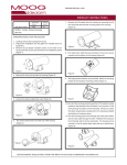
4. After the wall mount is securely attached to the wall, remove the (3) 10-32 tamper resistant screws with the provided security tool (Figure 3) and take off the access plate.
Tamper
resistant
screws
Access plate
Figure 3
STANDARD INSTALLATION PROCEDURE
ELECTRICAL SPECIFICATIONS (Camera with hardwire pan/tilt)
Power Source & Power Consumption
(includes: heater, blower and camera)
P/DDW10CR/02 P/DDW10CR2/02 P/DDW10CR3/02 -
WIRING (See wiring charts, next page)
115 VAC, 90 vA, 0.8 Amps
24 VAC (Class 2), 90 vA, 3.75 Amps
220 VAC, 90 vA, 0.45 Amps
FOR NON-PRESSURIZED VERSION
5. Run all electrical wiring through the bracket and out the access hole.
CAMERA SPECIFICATIONS
Resolution - 470TVL - NTSC, 460TVL - PAL
Minimum Illumination - 0.2 Lux B&W mode, 3.0 Lux color mode
Zoom Ratio - 18X, 4.1 - 73.8mm optical, 216x digital
Format - 1/4"
White Balance - Auto
Electronic Shutter - 20 step
6. Attach appropriate connectors to incoming wiring (Figures 5 and 6). The housing has
two inputs for power - one for heaters, and one for camera and blower. See the general
specifications for current draw at the appropriate voltage.
FOR PRESSURIZED VERSION
5A. Connect incoming power and video wires to the connector supplied. (Figures 7 and
8 for pin out on connector.)
WALL MOUNT INSTALLATION:
1. Remove the (2) tamper resistant screws on the top of the housing with the security tool provided in the installation packet
(Figure 1, next column).
NOTE: It is helpful to attach short leads (2.00") to the video pins and solder these to
the video shield on the coax cable. Use an insertion tool to assist with the assembly of
the connector.
6A. Connect the 18-pin connector to the housing.
7. With the mounting bracket securely mounted and all wiring connections completed,
the next step is adjusting the pan/tilt.
Tamper
resistant
screws
Figure 1
2. Loosen the (4) flange nuts, and turn the housing clockwise to remove the housing
from the wall mount (Figure 2).
Flange nuts
Figure 2
3. The wall mount can now be attached to the wall with appropriate fastening hardware.
-4-
CAUTION: Using smaller than recommended cable sizes can result in poor performance
and damage to the heater and camera.
Wiring Chart Non-Pressurized Receiver Version
A.Heater
1)Red - Heater 1
2)N/C
3)Red - Heater
B.Camera Power
1)Black - V2
2)Orange - V1
C.RJ45
Wire Gauge
VA
22
70
25ft
7 m
20
40 ft
14 m
18
64 ft
20 m
16
100 ft
30 m
14
162 ft
50 m
12
260 ft
80 m
INSTALLING THE PAN/TILT
1. Slide the pan/tilt back into place. All of the electrical connections are made by the
edge connector and will be engaged at that point.
A
2. Place the pan/tilt inside the housing so that the alignment pins are facing the housing
PC board. The two vertical flanges on the pan/tilt quick release plate should slide in
between the two vertical flanges on the housing plate. There are also notches on the back
side of the quick release plate that align with support tabs on the housing plate (Figure 8).
B
Figure 8
C
3. With the two vertical flanges lined up and the quick release notches inserted through
the support tabs, slide the pan/tilt side ways, towards the housing PC board. There are
two alignment pins on the front of the quick release plate that will engage with holes on
the housing bracket. The pan/tilt should be pushed side-ways until the panel fastener
aligns with the mating insert in the housing plate. Be gentle with the pan/tilt because
the wiring connections are being made as the pan/tilt is being slid sideways (Figure 9).
Figure 5
Wiring Pressurized Receiver Version
Figure 7
Video
Shield
Front View
B
A
L
N
M
Alarm Common
K
TXA
TXB
NC
NC
U
P
C
T
Side View
Alarm In 2
Alarm In 3
J
Alarm In 1
R
D
H
S
NC
RXA
RXB
E
G
F
Edge
Connector
Camera Power
Heater /Blower
Figure 9
Camera Power
Heater /Blower
The following chart is provided as a general guide for the input power for heater,blower
and camera, between the housing and power supply.
Wiring Pressurized Network Version
White/Orange
Orange
Figure 7A
B
White/Green
NC
Green
NC
GND
NC
Heater /Blower
A
L
N
M
U
P
C
R
D
E
T
J
H
S
F
Alarm Common
K
G
Alarm In 2
Alarm In 3
Alarm In 1
4. Tighten the panel fastener with a long Phillips screwdriver (Figure 10).
Panel
Fastener
Figure 10
NC
Camera Power
Camera Power
Heater /Blower
-5-
5. Reattach the bullet-resistant liner. Make sure that the viewing slot is in front of the
ballistic window. Each liner arm has an alignment pin that mates with a hole on the
ballistic. When both pins are aligned with their appropriate alignment hole, the (4) Phillips
head captive screws will align with inserts on the liner arms. Tighten the (4) screws to
secure the liner.
6. The liner should still be able to move up by about 1/16" on an inch to allow the liner
to move when shot and transfer the force to the housing instead of the pan/tilt.
REATTACHING THE DOME ON PRESSURIZED UNITS
1. The dome on the pressurized unit must be attached correctly for the unit to function
properly. All screws and posts must line up exactly.
INSTALLING THE HOUSING ON THE BRACKET
1. Make sure that the (4) flange nuts on top of the DeputyDome™ are loosened
and that the tamper-resistant screws are not attached. Lift the unit up to the wall
mount and align the flange nuts with the keyhole slots on the mount (Figure 11). Turn
counterclockwise so that the nuts are inside the slots. Make sure that the holes for the
tamper-resistant screws line up. Tighten the flange nuts.
2. There are two posts on the underside of the dome which must be placed in the proper
slots on the housing (See Figure 13). One is located on the lanyard side of the dome and
the other is on the opposite side. The dome is oriented properly when the lanyard can
be attached to the housing.
IMPORTANT NOTE: For non-pressurized units make sure the wiring on top of the housing
is fed through the opening on the bottom of the wall mount. On pressurized units the
connector will fit directly into the opening.
Flange nuts
Figure 11
Lanyard
Posts MUST fit
in these slots
(one on either
side)
2. Reattach and tighten the (2) security screws (Figure 12).
Post (one on
either side)
Lanyard screw hole
on housing
1/4 - 20 Security Screws
Figure 12
3. Make all wiring connections.
NOTE: On non-pressurized versions be sure to cover the BNC connectors with electrical
tape to help prevent a short between the wall mount bracket and the video wiring.
4. Double check all wiring and push it back through the access opening into the wall mount
bracket. FOR PRESSURIZED HOUSINGS: At this point, pressurize the housing following the
instructions on page 7.
5. Reattach the access cover.
6. Test the function of all the equipment.
7. Reattach the lower dome with the tamper-resistant screws and security tool used earlier.
FOR PRESSURIZED HOUSINGS: See the important instructions on the next page for
reattaching the dome.
-6-
Close Up View of Dome
Figure 13
IP Instructions
The factory default IP adress is 192.168.0.200.
See IP Ready camera instruction for installation details.
For Pan/Tilt control click on PTZ control icon in top right corner.
Pan/Tilt control contains standard pan/tilt/camera control functions.
To save preset, pull down #1 preset, move camera to desired position and then hit
"save" to save preset.
You can store up to 18 presets. Adjusting "speed" setting will correspondingly adjust
dwell time when the preset is saved. Use low numbers for longer dwell.
To modify camera setting, select preset "95." Set speed control to "9," then use up/
down and left/right to access sub-camera menu.
Scroll to Exit
*Tour button will allow you to tour sequentially through presets.
Pan/Tilt
functions (also
used to scroll
camera menu)
Use to save
or remove
PreSets
Select
PreSets
Lens
Functions
-7-
PROCEDURES FOR PRESSURIZED HOUSINGS
Filling and Refilling
Pressurized housings provide maximum protection for CCTV cameras and lenses. The
charge of dry nitrogen inside the housing eliminates the effects of moisture, dust,
insects and corrosive exhaust fumes. This allows a longer lifetime for your surveillance
equipment.
To fill (or refill) a pressurized housing, you must have the following:
1. Attach the barb to the regulator.
2. Remove the cap from the Schraeder valve.
3. Set the gauge on the regulator to between 5 and 8 psi.
2. A regulator on the tank
4. Place the air chuck on the Schraeder valve, just as you would on a tire, and press
down to begin filling. Continue until the regulator stops feeding nitrogen into the
housing and begins to let off excess pressure. In addition, as dry nitrogen is inserted
into the housing the humidity strip will change from pink to blue.
3. A hose with air chuck to connect the regulator to the housing’s intake valve
CAUTION: Do not attempt to fill beyond this point.
Dry Nitrogen
NOTE: The humidity sensitive tape will appear blue under normal dry conditions. The
tape will turn pink if exposed to moisture or humidity
1. A tank of dry nitrogen (or oxygen)
Nitrogen is a readily available. To obtain supplies, check your local yellow pages for a
medical or industrial gas provider. If the tank is to be carried from location to location,
a size of 40 cubic foot is recommended. This should be enough to refill 30 individual
housings. Handle the tanks with care. Although nitrogen is an inert gas, the tank is
highly pressurized and if the valve or regulator is damaged the tank could be dangerous. Tanks of dry nitrogen can be kept for several years.
5. Replace the metal cap on the Schraeder valve. The cap must be installed on the
Schraeder valve (air input valve) to ensure an airtight enclosure.
6. Check the pressure in the unit with a pressure gauge. It should be 5psi.
7. Reattach wall mount access cover plate.
The Regulator
The tank will have a standard 580 fitting, but a regulator will be required. A
recommended regulator for the tank would be a Harris #9296-15-580 or
#425-15-580. For local distribution you can contact Harris at 800-241-0804.
NOTE: If you have removed the dome it must be reattached and oriented properly.
See page 5 for complete instructions.
The Hose
The purge valve, called a “Schraeder” or “dill” valve, is similar to the air intake valve on
car or bicycle tires. To connect the regulator to the purge valve on the housing, you’ll
need a hose with a 1/4” barb on one end and an air chuck on the other. The barb
connects to the regulator, the air chuck to the Scraeder valve. These hoses can be
obtained at local auto parts stores.
PRECAUTIONS:
1. Always use safety goggles when servicing the unit.
2. Inspect the enclosure upon opening the product and be sure the unit has not been
damaged during shipping. Domes that have been cracked or show any signs of
damage should be replaced immediately.
3. Pressurize the unit with air or dry nitrogen only.
4. Do not fill the housing to more than 5 psi maximum pressure. Exceeding 5 psi will
damage the enclosure.
5. Never use an unregulated air supply to pressurize the enclosure. The valve should
be regulated to allow a maximum air pressure of 10 psi.
6. Be sure you periodically examine the unit and the attached supporting structure.
If the dome shows any signs of wear, such as stress cracking, it should be replaced
immediately.
-8-
Exploded View for Replacement Parts
2
1
3
8
4
5
9
6
7
11
10
12
13
13
15
82
16
81
17
19
18
20
22
21
-9-
Exploded View for Replacement Parts
(Pan/Tilt Assembly)
25
26
27
28
29
30
31
- 10 -
Exploded View for Replacement Parts
(Pan Bearing Assembly)
35
37
36
38
39
40
- 11 -
Exploded View for Replacement Parts
(Network Assembly)
81
81
81
16
82
- 12 -
Replacement Parts List
Part No.
Description
1
91-NTFL01
3/8-16 Flange Nut (4)
2
90-BTSEC06
1/4-20 x 1/2" Security screw SS (2)
3
50-VL1428
DDWC10 housing body
4
30-VL1405
DDWC10 accs mounting bracket
5
92-WSFL01
1/4 Flat Washer SS (4)
6
92-WSSL01
1/4 Split Lockwasher SS (4)
7
90-BTHH32
1/4-20 x 1/2" Hex head bolt SS (4)
8
90-BTRP31
8-32 x 3/8" Grounding screw
9
71-BLEH24
Blower, 24VDC 60MM
10
70-WPTRAN/P2
240/120V: 1.5A 24V Transformer
11
92-WSTH02
#8 Star washer (8)
12
91-NTHH06
8-32 Hex nut SS (4)
13
76-DD01PCB
DDWC10 Housing PCB
16
RP-30VL2678
Network Bracket
17
90-BTRP20
#10-32 x 3/8" pan head screw SS (4)
18
92-WSTH04
#10 Star washer (3)
19
DDWC10 Heater (2)
20
96-RSORNG
1/4 O-ring (3)
21
RCDWW10
Clear dome for DeputyDome™
22
90-BTSEC04
1/4-20 x 3/8" security screws (3)
25
90-BTHH33
5/16-18 x 3/4 Hex head bolt SS (3)
26
92-WSSL02
5/16 Split Lockwasher SS (3)
27
30-VL1408
DDWC10 P/T Quick release bkt
28
96-MPDDW
Pan/tilt mounting pad
29
DDWC10 pan/tilt
30
30-VL1313
DDWC10 rotating liner
31
95-FSC04
10-32X1/2" Captive screw (4)
35
DDWC10 bearing assembly
36
60-4011
18 tooth 1/5" belt drive pulley
37
60-4015
55 tooth 1/5" timinig belt, pan
38
60-4013
36 tooth 1/5" belt drive pulley, DD pan
39
90-BTHH37
8-32 x 1/2" Trimmed hex head SS (8)
40
92-WSTH02
#8 Star washer (5)
81
RP70P1401S
Network Card and Bracket
82
RP-70TRANS03
Power Converter
- 13 -
Product Registration/Warranty
Thank you for choosing Moog Videolarm. We value your patronage and are solely committed to providing you with the highest
quality products available and superior customer service.
Should a problem arise, rest assure that Moog Videolarm stands behind its products by offering impressive warranty plans: 3 Years on all Housings, Poles,
Power Supplies, and Accessories and 5 Years on camera systems (SView, QView, Warriors), and InfraRed Illuminators.
Register Your Products Online
Take a few moments and validate your purchase via the Online Product Registration Form at
www.videolarm.com/productregistration.jsp
Register your recent Moog Videolarm purchases and benefit from the following:
• Simple and Trouble-Free RMA process
• Added into customer database to receive product updates / news
• Eliminate the need to archive original purchase documents:
Receipts, Purchase Orders, etc…
- 14 -