1
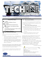
VOLUME 6 NUMBER 2
AN EXCHANGE OF TECHNICAL INFORMATION
ABOUT CARRIER TRANSICOLD CONTAINER PRODUCTS
Inside This Issue
September 2001
New Container Web Site
On August 15th all Carrier Container web applications
were moved to an new and updated web site to provide a better
look and feel and to allow more features to be built into the site.
The address of the new site is
FAQ's
Megohm Readings on heaters
TechTips
Control Transformer Replacement
Cd29 Failure Action/Response Mode
General
Troubleshooting electronic chart recorders
New Container Web Site
DataLine for Windows
Control Transformer Replacement
http://www.container.carrier.com
There are two options when selecting a replacement Control
Transformer.
1. Part number 10-00332-21SV is used on a standard 69NT base unit
and can replace the following part numbers: 10-00332-00, 10-0033204, 10-00332-06, 10-00332-10, and 10-00332-20SV.
2. Part number 10-00332-07 is a large capacity transformer and is used
on 69NT Controlled Atmosphere units, or units equipped with a
60-amp contactor. This is the only transformer that can be used to
replace the following part numbers: 10-00332-01, 10-00332-02, 1000332-03, and 10-00332-05.
BEFORE PROCEEDING WITH A TRANSFORMER REPLACEMENT,
Verify that the correct transformer has been selected as a replacement.
Use of the standard transformer in place of the large capacity transformer
will result in early failure of the replacement transformer
For specific instructions to install the replacement transformer consult
the instructions that are supplied with each trasformer when it is purchased.
For those who have either of our previous websites bookmarked
the following will happen when you access the site;
1. From www.carrier.transicold.com, you will be taken to a gate
way page which gives you the choice of which website you
want to go to, select Container and you will be taken to the
new website.
2. From www.carrier.refrigeration.com, when you select
Container you will be taken direct to the new site.
Listed are changes that were implemented on the new web site
Revised Service Center directory- Allows rapid selection by
World/Region maps of the Service Centers that interest you.
Direct Email links included to assist you in contacting a Service
Center. Direct links to Service Center websites
On line Manuals- The most recent Operations and Service manuals as well as Parts Lists are available on the site and downloadable
in Adobe PDF format. Base models are 69NT40-511-3XX,
69NT40-531, 69UG15 and 69RG15 generator manuals,
NatureFresh supplement, model configuration manual.
(Continued on back page)
TechLine is a publication of Carrier Transport
Refrigeration
Editor: David Whyte
Contributors: Mark Donahoe, Mark Rogers, Perry
Hoover, Zvonko Asprovski, David Whyte
Please circulate this newsletter to all of your support personnel
Carrier Transport Refrigeration
P.O. Box 4805,
Syracuse,
New York 13221,
Telephone +1-315-432-7688
Fax +1-315 -432-7698
TROUBLESHOOTING ELECTRONIC CHART RECORDER
The following procedure is designed to assist the technician in determining a fault in the chart recorder.
(Note: This procedure needs to be performed with the refrigeration unit running unless otherwise stated.)
Required tools:
Digital Multi-meter, Interrogation Device (PC or Datareader)
SET-UP INFORMATION
Verify unit configuration (code 20) matches that on the nameplate of the unit. If they do not match, use the configuration
card to reconfigure the microprocessor to the correct model number.
Determine which sensor is being used for recording purposes. The models listed below have a default setting to record with
either sensor, based on the setpoint (perishable settings, set points above 14°F/-10°C use the supply sensor and frozen settings
below 14°F / -10°C use thereturn sensor); all other models are set for return temperature sensor recording only.
69NT40-511-96
69NT40-511-328 - 336
69NT40-511-351
69NT40-531-300
69NT40-511-313 - 316
69NT40-511-338
69NT40-511-353
69NT40-511-319
69NT40-511-341 - 345
69NT40-531-3 - 05
69NT40-511-321 - 325
69NT40-511-350
69NT40-531-202
Compare the chart temperature to the appropriate recording sensor (dC01 if using supply air sensor or dC02 if using the
return air sensor). If temperatures or dates do not match proceed with the troubleshooting procedure.
STYLUS CALIBRATION PROCEDURE
1.
Perform the calibration test procedure according to the label on front of the recorder. If OK proceed to the communication
procedure; otherwise proceed to voltage and wiring procedure. NOTE: Under no circumstances should the recorder stylus
be moved by hand across the chart.
VOLTAGE AND POWER WIRING CHECK PROCEDURE
1.
2.
3.
4.
5.
Unplug the connector located at the bottom of the chart recorder. Check the voltage from the controller at pin 1 (white wire)
to pin 8 (blue wire) on the female plug. If voltage is between 18 - 30 VAC proceed to step 5. If not continue to step 2.
In the refrigeration control box, check the in-line fuse located on the white wire (CR1-ST10) coming from the start stop
switch. If the fuse is good proceed to the next step. If the fuse is defective, replace the fuse and repeat step one. Note: if fuse
blows on replacement, change the chart recorder. If the fuse is OK continue to step 3.
In the refrigeration control box: check that voltage between QC1 and TP9 on the controller is between 18 - 30VAC. Make
sure the wire is still connected to the controller during this check. This voltage is supplied from the start/stop switch. If the
voltage is OK proceed to step 4. If not troubleshoot the refrigeration unit.
Turn unit off. Using an ohm meter check the continuity of the wiring from the controller to the female connector (CR) at
the chart recorder. CR1 - ST10 / CR2 - MA5 / CR3 - MA3 / CR4-MA9x / CR5 - MA7 / CR6 - MA11 / CR8 - TP9.
Correct any loose wires or miss-connections and retest.
At the male connector located on the bottom of the chart recorder give each wire a light pull to ensure that the pins are prop
erly connected. If OK continue to check the communications. If not OK correct any loose connections and repeat test. If
calibration again fails replace the recorder.
COMMUNICATION AND COMMUNICATION WIRING CHECK PROCEDURE
1.
2.
Connect an interrogation device (Datareader or PC) to the unit using the proper cables and activate the interrogation
program (Datareader, Dataview, DataLine).
Is communication established with the controller? If so the communication is OK, proceed to chart rotation check. If there
is no communication established, using and ohm meter check the wiring from the interrogation connector to the "EC con
nector" on the back side of the controller. If wiring is OK replace the chart recorder and verify communications are estab
lshed with the new recorder. If not, correct wiring connections and retest.
CHART ROTATION CHECK PROCEDURE
1.
2.
3.
Verify that the chart nut is secure (do not over tighten as it could lead to failure of the gears).
For chart recorder models 12-00464-05 and above (part number is located at top right corner of the controller) follow the pro
cedure located on the front of the recorder. If chart does not rotate replace the recorder and retest.
For all other models, run the unit for 3 hrs and confirm chart rotation. If chart does not rotate replace the recorder.
* Mark Rogers, Zvonko Asprovski and Perry Hoover,
Troubleshooting Procedure
Read the troubleshooting set-up information and proceed as follows.
Perform STYLUS
CALIBRATION
procedure on front of
chart recorder
NO
Replace
the Inline
Fuse
YES
Voltage Check Procedure
Unplug the connector at the bottom
of the chart recorder and check
voltage between Pin 1 (white wire)
to Pin 8 (blue wire)
NO
NO
Able to
Calibrate?
Voltage
is between
(18-30
vac)
Verify wires are
properly seated in
the connector on
the recorder.
Pull test
Able to Calibrate?
YES
Inline
fuse is
Good?
YES
Perform
Communications
Procedure
NO
YES
Check the voltage
at QC1 to TP9 with
the wire connected
and the unit
running (18 vac)
NO
Verify wiring
from
interrogation
plug to EC
connector is
OK
Is
communication
with controller
established?
NO
YES
Turn unit off Check
Continuity between
controller and
recorder and repair.
YES
Voltage is
between
(18-30)
YES
Perform
CHART
ROTATION
Procedure
NO
NO
Chart
Rotation
is okay
YES
Troubleshoot
Reefer unit
Replace chart
Recorder
Chart
Recorder is
okay
Cd 29: User Selectable Failure Action/ Response Mode
Function code 29*, is user selectable code that defines the mode of operation of the refrigeration unit** during the presence of active alarm 26 (all
four control sensors failure), or 27 (probe circuit calibration failure).
The user can select one of four possible actions as designated by the selection code:
A – Full Cooling (SMV 100%)
B – Partial Cooling (SMV 50% open)
C – Evaporator Fan Only
D – Full System Shutdown – Factory Default
For the desired selection to automatically take place the failure action mode must be selected prior to the unit failure occuring (active alarm 26 or
27). Note: Once the unit goes into the selected failure mode of operation, it can be changed as follows:
1. Access code 29 and change it to the new/desired setting (A, B, C, or D).
2. Turn the unit OFF for several seconds, and then turn it back ON. The unit will start running in the newly selected mode.
3. Repeat the above steps if different action mode is needed.
* Function code number 28 is used in Micro-Link 1 units.
** Applicable to ML1, ML2, and ML2i units.
Note: The above procedure should be utilised only on an emergency basis, and unit must be repaired as soon as possible.
*Mark Rogers, Zvonko Asprovski
FAQ
Q:
What is the minimun megohm reading you should accept on heaters?
A:
Even though the standard land based practice of 1 megohms would be sufficient, most ships have the earth leakage alarms set for 2
megohms, therefore 2 megohms should be the minimum acceptable value.
For reading between 1 and 2 megohms, operate the heaters for 10-15 minutes, if the resistance reading rises above 2megohmzs they are OK. In
most cases the megohm reading will either rise significantly above 2 megohm, as free moisture has been removed or drop below 1 megohm, as the
fault situation has been aggravated. Heaters with readings below 1 megohm should be replaced. The testing should be carried out with a 500v
Insulation tester and not a standard 5v multimeter.
*Mark Donahoe
Dataline for Windows
Early last month the Windows version of the DOS Dataview program, DataLine, was released. This program is now available from
your local regional warehouse as part number 07-00421-00 for a single license copy. If you require additional licenses at the time you
purchase your copy of DataLine use part number 07-00426-00 for the additional licenses. To obtain full details of Dataline and to
get Brochures or Operating manuals go to http://www.container.carrier.com
New features in Dataline,
Eight reports pre formatted and ready for use.
Save your data to standard ASCII format for import into MicrosoftTM Excell or Word.
Print to any printer.
Ready for use on Windows 95B, 98, NT.
*David Whyte
New web site (continued from Front Page)
On line Equipment Brochures- Download Adobe PDF versions of any current Carrier Container equipment.brochures,
Refrigeration and Generator units, DataLine softeware etc.
Training - Online registration for all Container training classes worldwide
CPG Contacts - Complete list of all contacts in Carrier Container Division.
User Portals - Access all Authorised User applications through the new TransCentral Customer Portal on the Home Page. Allowing
a single entry of your ID and password to access all the applications you currently use with Carrier Transport.
Any comments you may have about this new website or features you would like to see added can be emailed to
[email protected].
*David Whyte
Please circulate this newsletter to all of your support personnel
www.container.carrier.com
Emergency 24-Hour Technical Assistance
800-668-6823 (800-ONTO-CTD)