1
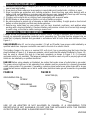
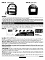
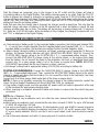
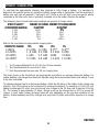
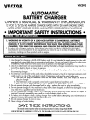
PERSONAL PRECAUTIONS AND SAFETY
1. Someone should be within range of your voice or close enough to come to your aid when you work
near a lead-acid battery.
2. Have plenty of fresh water and soap nearby in case battery acid contacts skin, clothing, or eyes.
3. Wear complete eye protection and clothing protection. Avoid touching eyes while working with a
battery. Acid, acid particles or corrosion may get into your eyes. Immediately flood eye with running
cold water for at least 10 minutes and get medical attention immediately.
4. if battery acid contacts skin or clothing, wash immediately with soap and water.
5. NEVER smoke or allow a spark or flame in vicinity of battery or engine.
6. Be extra cautious to reduce risk of dropping a metal tool onto battery. It might spark or short-circuit
battery or other electrical part that may cause explosion.
7. Remove any metal items on your person such as rings, bracelets, necklaces, and watches when
working with a lead-acid battery. A lead-acid battery can produce a short-circuit current high enough
to weld a ring, or the like to metal causing a severe burn.
GROUND AND AC POWER CORD CONNECTION
Charger should be grounded to reduce risk of electric shock. Charger is equipped with an electric cord
having an equipment grounding conductor and a grounding lug. The plug must be plugged into an
outlet that is properly installed and grounded in accordance with all local codes and ordinances. (See
Figure 1.)
DANGER! NEVER alter AC cord or plug provided if it will not fit outlet, have proper outlet installed by a
qualified electrician. Improper connection can result in the risk of an electric shock.
—
This battery charger is for use on a nominal 120 volt circuit, has a grounding plug that looks like the
plug illustrated in Figure 1 A. A temporary adapter, which looks like the adapter illustrated in Figure 1 B,
may be used to connect this plug to a two-pole receptacle as shown in Figure 1 B, if a properly
grounded outlet is not available. The temporary adapter should be used only until a properly ground ed
outlet can be installed by a qualified electrician.
DANGER!
DANGER! Before using adapter as illustrated, be certain that center screw of outlet plate is grounded.
The green-colored rigid ear or tab extending from adapter must be connected to a properly grounded
outlet- make certain it is grounded. If necessary, replace original outlet cover plate screw with a longer
screw that will secure adapter ear or tab to outlet cover plate and make ground connection to grounded
outlet.
FIGURE lA
FIGURE lB
ADAPTER (B)
GROUNDING PIN (A)
SCREW
METAL
GROUNDING
MEANS
USE OF AN ADAPTER IS NOT ALLOWED IN CANADA. IF A GROUNDING TYPE
RECEPTACLE IS NOT AVAILABLE, DO NOT USE THIS APPLIANCE UNTIL THE PROPER
OUTLET IS INSTALLED BY A QUALIFIED ELECTRICIAN.
2
VEC093
PREPARING TO CHARGE
1. Determine voltage of battery by referring to car owner s manual.
2. if it is necessary to remove battery from vehicle to charge, or to clean terminals, always remove
grounded terminal from battery first. Make sure all accessories in the vehicle are off, so as not to
cause an arc.
3. Clean battery terminals. Be careful to keep corrosion from coming in contact with eyes.
4. Add distilled water in each cell until battery acid reaches level specified by battery manufacturer. This
helps purge excessive gas from cells. Do not overfill. For a battery without cell caps, carefully follow
manufacturer*s recharging instructions.
5. Study all battery manufacturers* specific precautions such as removing or not removing cell caps
while charging and recommended rates of charge.
6. Be sure area around battery is well ventilated while battery is being charged. Gas can be forcefully
blown away by using a piece of cardboard or other nonmetallic material such as a fan.
7. Make sure the initial charging rate is not over battery manufacturer*s suggestion.
CHARGER LOCATION
1. Locate charger as far away from battery as cables permit.
2. Never place the charger directly above battery being charged; gases from battery will corrode and
damage charger.
3. Never allow the battery acid to drip on charger when reading gravity or filling battery.
4. Do not operate charger in a closed-in area or restrict ventilation in any way.
5. Marine batteries must be removed and charged on shore.
6. Do not set a battery on top of charger.
DC CONNECTION PRECAUTIONS
1. Connect and disconnect DC output clips only after removing AC cord from electric outlet.
2. Never allow clips to touch each other.
3. Attach clips to battery posts and twist or rock back and forth several times to make a good
connection. This tends to keep clips from slipping off terminals and helps to reduce risk of sparking.
FOLLOW THESE STEPS WHEN BATTERY IS INSTALLED IN VEHICLE. A SPARK NEAR BATTERY MAY CAUSE
CAUSE
BATTERY EXPLOSION. TO REDUCE RISK OF A SPARK NEAR BATTERY:
a. Position AC and DC cords to reduce risk of damage by hood, door, or moving engine part.
b. Stay clear of fan blades, belts, pulleys, and other parts that can cause injury to persons.
c. Check polarity of battery posts. POSITIVE (POS, P, +) battery post usually has larger diameter
than NEGATIVE (NEG, N,-) post.
d. Determine which post of battery is grounded (connected) to the chassis. If negative post is
grounded to chassis (as in most vehicles), see (e). If positive post is grounded to the chassis,
see (f).
For negative-grounded vehicle, connect POSITIVE (RED) clip from battery charger to POSITIVE
(P05, P, +) ungrounded post of battery. Connect NEGATIVE (BLACK) clip to vehicle chassis or
engine block away from battery. Do not connect clip to carburetor, fuel lines, or sheet-metal
body parts. Connect to heavy gauge metal part of the frame or engine block.
f. For positive-grounded vehicle, connect NEGATIVE (BLACK) clip from battery charger to
NEGATIVE (NEG, N, -) ungrounded post of battery. Connect POSITIVE (RED) clip to vehicle
chassis or engine block away from battery. Do not connect clip to carburetor, fuel lines, or
sheet-metal body parts. Connect to a heavy gauge metal part of the frame or engine block.
g. When disconnecting charger, disconnect AC cord, remove clip from vehicle chassis, and then
remove clip from battery terminal.
h. See operating instructions for length of charge information.
i. Do not charge the battery while the engine is operating.
VEC093
3
INTRODUCTION AND FEATURES
Thank you for selecting the Vector Model VEC093 2/10/20/40 Amp 12 volt Smart Battery Charger, with
Engine Start, Alternator Voltage Check and Battery Restore modes. With proper care and use, it will give
you years of dependable service. This model battery charger has a high charge rate of up to 40 amps,
and low charge rate of up to 2 amps. It is intended for charging only 12 volt lead-acid batteries
maintenance free, conventional automotive, marine deep cycle and gel - that are usually used in cars,
trucks, farm equipment, boats, RVs and SUVs, lawn mowers and garden tractors, motorcycles, personal
watercraft, snowmobiles, ATVs, trucks and various commercial applications.
-
Vector Smart Chargers are microprocessor-based and have a charge curve that has three stages. (See
Figure 2). Stage One is essentially a constant current charge. This continues until the connected battery
is about 85 percent charged. When Stage One ends, the charger briefly sounds a tone (beep) to
indicate a change to Stage Two, the Absorption Phase. This stage is essentially a constant voltage phase
and supplies approximately 10 percent of the charge. At the end of Stage Two, the charger changes
output to Stage Three. Stage Three continues and turns OFF when the battery reaches full charge. This
charger has a CHARGING COMPLETE LED and the digital display shows FUL when the battery is fully
charged.
Stage One
FIGURE 2 CHARGE CURVE
BEEP
BEEP
--
Three
COMPLETE LED LIT
FEATURES
! The unit has three charge rate setting, with a 2/10/20/40 pushbutton charge rate switch:
a) 2 amps: smaller batteries as in lawn mowers, snowmobiles, motorcycles, etc.
b) 10 amps: middle sized batteries such as in small cars
c) 20 amps: automobile.
d) 40 amps: large truck batteries, banks of RV batteries.
! Microprocessor controlled for proper operation and for fault detection.
! Large Lighted Digital Display, shows charging current, and codes that indicate faults, and modes of
operation and timeout of functions.
! High Frequency operation for pure DC output.
! Rapid charging three stage output.
! Heavy-duty cables and clamps are corrosion-resistant for better connections.
! Connect to side, or top-mount battery terminals.
! Rugged case with baked on finish, plus sturdy carry handle.
! Self storage of cables and clamps.
! Ideal for charging during winter season when the starting performance of vehicle batteries is lowered
by cold or extreme weather conditions.
! Single beep tone indicates a button is pressed or a mode change occurs.
! Battery Recondition mode provides desulfation of battery plates to improve battery performance.
! Alternator Voltage Check can confirm proper operation of the alternator and indicate less than full
output.
4
VEC093
CHARGE RATE SELECTION
After the clamps are connected, plug in the charger to an AC outlet and the charger will show a
circulating pattern on the Digital Display. This pattern indicates power is a p plied. Press the ON/OFF
button to prepare the charger to change to an operating mode. Press the 2/10/20/40 button and the
charger will begin charging at 2 Amps. Pressing the 2/10/20/40 switch again will advance the charge
rate to 10A, then 20A, then 40A. Pressing the switch again will turn OFF the charger output and the
display will show the circulating pattern.
Note that each time the charger rate is changed, the charger sounds a beep tone. The only time the
selected charge rate does not display at the full selected rate is when the battery is nearly full and
charging at either steps two or three. The display will be showing a slowing charge rate. To return to
2A, press the 2/10/20/40 button. When the battery is fully charged, the charging Complete LED is lit
and “FUL” is displayed on the Digital Display.
CONNECTING IF BATTERY IS INSTALLED AINVEHICLE
a) Check polarity of battery posts For top-mounted battery connectors, the Positive post (marked POS,
P, +) usually has a larger diameter than the Negative battery post (marked NEG, N, -). For sidemounted battery connectors, the terminals are marked Positive -red and Negative -black.
b) Attach charger clamps to battery connections, as follows, ensuring a good connection (if there is a
mistake, the Reverse Polarity Indicator will light): NEGATIVE-GROUNDED VEHICLE: Connect the
POSITIVE (RED) charger clamp to the POSITIVE (POS, P, +) ungrounded battery terminal. Then,
connect the NEGATIVE (BLACK) charger clamp to the vehicle chassis, or the engine block (away
from the battery). Do not connect the clamp to the carburetor, fuel lines, or sheet-metal body parts:
connect only to a heavy gauge metal p art of the frame or engine block. NOTE: NEGATIVEGROUNDED type systems are the most common in today*s vehicles.
c) Set charger*s charge rate to appropriate setting 2/10/20/40A according to battery size.
-
POSITIVE-GROUNDEDVEHICLE: Connect the NEGATIVE (BLACK) charger clamp to the NEGATIVE
(NEG, N, -) ungrounded battery post. Then, connect the POSITIVE (RED) battery clamp to the vehicle
chassis or engine part (away from the battery). Do not connect the clamp to the carburetor, fuel lines,
or sheet-metal body parts:
connect only to a heavy gauge, stable metal part of the frame or engine block.
NOTE: If there is any problem connecting the charger clamps to the battery terminals, contact the
Vector Technical Support Department toll-free at (866) 584-5504 for assistance.
d) Plug battery charger power cord into grounded AC power outlet and refer to Appendix A at the end
of this document for approximate charging times.
e) When charging is completed, disconnect cables and clamps in reverse order from which they were
connected.
NOTE: Use of Extension Cords
If it is necessary to use an extension cord, as is often the case, observe the following important safety
information:
! Before using any extension cord, ensure that the wire size is at least 12 AWG for up to 100 feet and
10 AWG for longer than 100 feet.
! Use only a good quality, good condition, UL-listed extension cord, and ALWAYS connect charger to
the extension cord before plugging the extension cord into a 110/1 20 volt AC power outlet. The use
of a poor quality extension cord or one that is not in good repair could cause fire and/or electric
shock.
! Use a three-wire extension cord with a 3-prong plug and 3-conductor socket.
VECO93
7
CONNECTING IF BATTERY IS OUTSIDE OF VEHICLE
a) Check polarity of battery posts- For top-mounted battery connectors, the positive post (marked POS,
P, +) usually has a larger diameter than the Negative battery post (marked NEG, N, —). For sidemounted battery connections the Positive terminal is red, the Negative terminal is black.
b) Attach a 24-inch (minimum length) 6 AWG insulated battery cable to the Negative battery post
(marked NEG, N, -)
c) Connect the Positive (RED) battery clamp to the Positive battery connector (marked POS, P, + or red).
d) Stand as far back from battery as possible, and do not face battery when making final connection.
e) Carefully connect the Negative (BLACK) charger clamp to the free end of the battery cable
connected to the negative terminal. Connect the charger*s power cord to a grounded 1 10/120 volt
AC power outlet, and refer to Appendix A for approximate charging times.
f) Set charger*s charge rate to appropriate setting according to battery size.
g) When charging is complete, disconnect cables and clamps in reverse order from which they were
connected.
CHARGING TIMES
The VECO93 is a fully automatic battery charger. It automatically adjusts the charge rate as the battery
becomes charged and stops charging when the battery is fully charged. if you require some estimate of
the time it takes to charge a battery refer to Appendix A for these details.
100A ENGINE START
e Engine Start Function can supply at least 100 Amps of current during engine starting. Follow all
battery, frame and AC connection precautions as if charging a battery in a vehicle. Observe the Reverse
Polarity LED and digital display to make sure that faults are not indicated. Pressing the 100A pushbutton
will immediately place the charger in the 40 ampere charge mode. The digital display will indicate a
countdown to “000". This initial charge on the battery makes sure that the battery is able to take a
charge. When the “000” count is reached, the Start Your Engine LED lights. This indicates that the high
current circuit is enabled and will energize when the engine starts cranking. Crank the engine using
manufacturer*s guidelines, typically in 3 to 5 second bursts. The high current engine starting function
requires a rest/cooling period between tries. Wait four to five minutes before a second cranking attempt.
During the rest period, the battery is charging at 40 amps. Crank the engine until it starts.
After the engine starts, press the ON/OFF button, disconnect the charger from AC, then frame and
battery connections.
RECONDITION MODE
NOTE: BATTERY RECONDITION mode does not charge any battery. Charging is a separate operation.
The battery to be treated does not have to be installed in a vehicle. Follow the instructions for
Connecting if Battery is Outside of Vehicle.
RECONDITION MODE should only be used with 10 Amp Hour or larger capacity lead-acid batteries.
Charge the battery to be treated for 20 minutes, before using RECONDITION Mode. Observe the
Digital Display for any codes. This initial charge will check the battery for shorted cells (F0l), open cells
or battery too low (or overcharged) to accept a charge (F02), and to ensure the battery can take a
charge. If code F03 is displayed, change modes to the
RECONDITION MODE.
Whenever a lead acid battery begins to discharge, lead sulfate, an insulator, begins to build up on the
plates in the battery. This reduces the ability of the battery to ho d a full char e. When that battery has an
immediate charge, most of the lead sulfate is dissolved and the plates are freed of this insulation. If a
battery remains in a discharged condition, the lead sulfate changes to a hard crystalline form, making a
full charge difficult. BATTERY RECONDITION mode sends a sequence of electronic pulses into the
battery, shaking loose and dissolving the crystals.
VECO93
This slowly (over 24 hours) removes the insulating buildup from the plates so the battery can hold a full
charge. Most automotive batteries (50 to 70AH) can be treated once to reduce the lead sulfate buildup.
Smaller 12 volt batteries, such as found in jump starters can be treated for 12 hours. However,
depending on the severity of lead sulfate buildup and a larger size of the battery, up to five 24 hour
treatments may be necessary. Battery Recondition mode automatically operates and then times out after
24 hours. When a smaller battery is treated, Battery Recondition mode can be manually stopped after
12 hours of treatment.
To start the RECONDITION MODE, press Battery Recondition. After 18 hours the timer will stop the
operation. You will see the circulating pattern, see Figure 4B.
ALTERNATOR VOLTAGE CHECK
NOTE: This check is not accurate for every make, manufacturer and model of vehicle. There is wide
variation in user-controlled electrical loads, alternator output, and wiring. Other factors include battery
condition, temperature, and engine idle speed. It is recommended to check your alternator when it is
known to be operating properly to verify that this check is valid for your particular vehicle.
The ALTERNATOR VOLTAGE CHECK measures a defined range of voltage that is available from the
fully charged battery. The user must allow the engine to warm to normal operating temperature and
achieve a normal idle speed. As many appliances as possible are turned off for the first part of the e
check to all ow the battery to reach it*s highest voltage level.
The Alternator Voltage Check is only activated after 10 to 30 minutes of engine idle. If the ALTERNATOR
GOOD LED Ii ts, then the ON/OFF button is pressed to stop the check. Alternator Voltage Check is
then repeated after many appliances are turned on to check the alternator output under a greater load.
If the first (unloaded) and second (loaded) checks indicate the alternator is good, then the entire
procedure should be repeated again. If after all appliances are turned on (except for air conditioning
and defroster), and the check shows Alternator Good LED lights, it is likely that the alternator is good.
NOTE: Do not turn on air conditioning, or the defroster system to load the alternator. These appliances
may start operating in the middle of a measurement cycle and give an invalid results.
If the first check indicates the alternator is good, and the second or third repeat of the check indicates
the alternator is bad, there probably is some problem in the system. Problems can range from loose fan
belts to a diode going bad in the alternator. To begin the check press Alternator and to stop the check
press ON/OFF. Note that the FAULT light will light when the Alternator is bad; a good Alternator will
light the Alternator Good LED.
NOTE:
NOTE: Do not charge the battery while waiting for the engine to warm. This will invalidate any alternator
voltage check. The Digital Display should show the circulating pattern while the engine is warming.
CARE AND MAINTENANCE
With only minimal maintenance, this Vector 2/10/20/40 Smart Battery Charger will deliver years of
dependable service. Follow these simple steps to maintain the charger in optimum condition:
! After each use, clean the battery charger clamps be sure to remove any battery fluid that will cause
corrosion of the copper clamps.
! Clean the outside case of the charger with a soft cloth and, if necessary, mild soap solution.
! Keep the charger cords loosely coiled during storage to prevent damage to the cords. Do not use the
charger if cords or clamps have been damaged in any way call Vector Technical Support
Department toll-free at (866) 584-5504 for details on replacing cords and clamps.
-
-
VECO93
TROUBLESHOOTING FAULT LED LIT
-
NOTE: Batteries below 4.0 Volts will not allow the charger to operate. if a 12 Volt battery is below 4.0
Volts it is probably either shorted, open or sulfated. Replace the battery.
The following conditions may light the FAULT LED:
! Poor connection to battery (or frame)
! Charging too fast - Decrease Charge Rate - Press 2/10/20/40A Push button to select lower rate.
! Charging too slowly - Battery is large and did not complete charging in 18 hours Press 2/10/20/40A
to charge at a faster rate
! Shorted battery cell Replace battery (F01)
! Open battery Cell Replace battery (F03)
! Battery sulfated have battery serviced or replace battery (F03)
! Reverse Polarity LED LIT - disconnect AC then reverse clamp locations on battery and frame.
! Internal over-heat in charger-make sure fan is not blocked. (F05)
Try charging another battery, if the FAULT LED does not light, then one of the above problems exists.
Charger will not charge and the fan will not operate if there is a fault. Call Vector Technical Support at
(866) 584-5504
-
-
-
-
SULFATED BATTERY(F03)
When batteries are left in a discharged state for a long period of time, they become “sulfated”. Sulfated
batteries cannot accept a high rate of charge since the internal plates are coated with lead sulfate. To
see if a battery in this condition can be “saved”, follow the instructions in battery recondition.
INTERNAL SHORT CELL BATTERY
(F01)
! If the battery being charged has internal short cell, the FAULT LED will light.
! Using a voltmeter, determine the voltage of the battery and if it is under 12 volts, the battery is
probably beyond repair or recharging, and will need to be replaced.
! If the voltage is over 12 volts, made sure there is no loading on the battery, resume the process
again.
BATTERY NOT ACCEPTING A CHARGE
! Make sure that the charger is plugged into a “live” 110/120 volt AC outlet.
! Unplug charger and check battery connections ensure that there is a good connection with the
battery terminal and/or vehicle chassis.
! Check to be sure that the battery is not sulfated.
! Check that the correct charge rate has been selected for the battery being charged.
! Ensure that enough charging time has been allowed for-check table in Appendix A for approximate
charging times.
-
VERY COLD BATTERY
If the battery to be charged is extremely cold (in temperatures less than freezing -0o C/32o F) it cannot
accept a high rate of charge, so the initial charge rate will be slow. The rate of charge will increase as
the battery warms.
WARNING: DO NOT attempt to charge a frozen battery.
10
VECO93
APPENDIX A CHARGING TIMES
—
To calculate the approximate charging time required to fully charge a battery, it is necessary to
determine the specific gravity (or, percent of battery charge) using a hydrometer. Use this technique if
battery vent caps can be removed. Check each cell. if there is one cell with a very low specific gravity
compared to the other cells, there is probably a shorted cell in the battery. Replace the battery.
The following chart converts hydrometer readings into percent of charge values.
SPECIFIC GRAVITY
PERCENT OF CHARGE PERCENT OF CHARGE NEEDED
(HYDROMETER READING)
IN BATTERY
BY BATTERY
1.265
100%
0%
1.225
1.190
75%
50%
1.120
0%
1.155
25%
50%
75%
100%
25%
Refer to the chart below for approximate charging times.
PERCENT OF CHARGE
2 AMPS
10 AMPS
20 AMPS
40 AMPS*
75%
6.5 HRS
1 .8 HRS
1 HRS
0.5 HRS
50%
12 HRS
3.0 HRS
1.5 HRS
0.8 HRS
25%
N.R***
4.5 HRS
3HRS
1.5 HRS
0%
N.R***
6 HRS
3.5HRS
1.8 HRS
* For Charging Batteries 80 to 100 AH (not for this example)
** Not Recommended for more than 1 hour
*** Not Recommended because over 18 hrs charging time.
The times shown in the chart above are approximate and refer to an average automotive battery. For
smaller batteries, the charge time should be adjusted using the formula shown below and adding 1 hour
to the time calculated.
To estimate charging time for a discharged battery, divide the AH rating of the battery by the charge rate
selected. This is the number of hours required to recharge the battery. For example, a 50 AH (12 volt)
battery is discharged (10 volts). How long should it be charged at the 20 Amp rate. Divide the 50 AH by
20. The answer is approximately 2.5 hours. Always round up the charge time by 10% to ensure full
charge. In most cases, battery recharge times will vary depending on the age and condition of the
battery. Smaller batteries should be charged at a lower rate (2 Amps) and add an extra hour to charge
time.
11
VEC093
VECTOR 5 YEAR LIMITED WARRANTY PROGRAM
This limited warranty pro ram is the only one that a p plies to this product, and it sets forth all the responsibilities
of Vector Manufacturing, Lt regarding this product. There is no other warranty, other than described herein.
!,
This Vector Manufacturing, Ltd. product is warranted, to the original purchaser only, to be free of defects in
materials and workmanship for five years from the date of purchase without additional charge. The warranty does
not extend to subsequent rchasers or users. Vector Manufacturing, Ltd. will not be responsible for any amount of
damage in excess of the retail purchase price of the product under any circumstances. Incidental and
consequential damages are specifically excluded from coverage under this warranty.
This product is not intended for commercial use. This warranty does not apply to accessories or damage to units
from misuse or incorrect installation. Misuse includes wiring or connecting to improper polarity power sources.
RETURN/REPAIR POLICY: Defective products, other than accessories, may be returned postage prepaid to Vector
Manufacturin g.Anydefective product, other than accessories, that is returned to Vector Manufacturing within 30
days of the date of purchase will be replaced free of charge. if such a product is returned more than 30 days but
less than five year from the purchase date, Vector Manufacturing will repair the unit or, at its option, replace it
free of charge.
if the unit is repaired, new or reconditioned replacement parts may be used, at Vector Manufacturing*s option. A
unit may be replaced with a new or reconditioned unit of the same or comparable design. The repaired or
replaced unit will then be warranted under the terms of the remainder of the warranty period. The customer is
responsible for the shipping charges on all returned items after 30 days. During the warranty period, Vector
Manufacturing, Ltd. will be responsible for the return shipping charges.
LIMITATIONS:
LIMITATIONS: This warranty does not cover accessories, bulbs, fuses and batteries, defects resulting from normal
wear and tear (including chips, scratches, abrasions, discoloration or fading due to usage or exposure to
sunlight), accidents, damage during shipping to our service facility, alterations, unauthorized use or repair,
neglect, misuse, abuse, failure to follow instructions for care and maintenance, fire, flood and Acts of God.
if your problem is not covered by this warranty, call our Technical Support Department at (954) 584-4446 or toll
free at (866)584-5504 for general repair information and charges if applicable. You may also contact us
through our website at www.vectormfg.com.
STATE
STATE LAW RIGHTS: This warranty gives you specific legal rights. Some states do not allow limitations on how long
an implied warranty lasts or the exclusion or limitation of incidental or consequential damages, so the exclusions
or limitations stated herein may not apply. This warranty gives the purchaser specific legal rights; other rights,
which vary from state to state, may apply.
TO REQUEST
REQUEST WARRANTY SERVICE FOR THIS PRODUCT: Contact Vector Manufacturing Technical Sup port by
telephone, fax or mail. We suggest that you keep the original packaging in case you need to ship the unit. When
returning a product, include your name, address, phone number dated sales receipt (or copy) and a description
of the reason for return and product serial number. After repairing or replacing the unit, we will make every effort
to return it to you within four weeks.
WARRANTY
WARRANTY ACTIVATION: Please complete Warranty Activation Card and mail to Vector Manufacturing. Enter
“VEC093” as Model and 12V Automatic Battery Charger 2/10/20/40A as “Product Type”. All Vector
Manufacturing, Ltd. products must be registered within 10 days of purchase to activate this warranty. Mail the
completed registration form, along with a copy of the original sales receipt to:
ATTN.: CUSTOMER SERVICE / VECTOR MANUFACTURING, Ltd.
4140 SW 28th Way, Ft. Lauderdale, FL 33312
PH: 954-584-4446 ! TOLL FREE: 866-584-5504 ! Fax: 954-584-5556.
You may also contact us at our web site www.vectormfg.com.
WARRANTY IS NON-TRANSFERABLE AND NON-REFUNDABLE.
12
VEC093