1
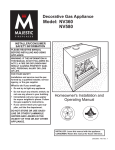
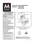
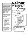
Decorative Gas Appliances
Models: NVBR36, NVBC36
NVBR42, NVBC42
INSTALLER/CONSUMER
SAFETY INFORMATION
NVBR36
PLEASE READ THIS MANUAL
BEFORE INSTALLING AND USING
APPLIANCE.
IMPORTANT: Read all instructions
and warnings carefully before starting
installation. Failure to follow these instructions may result in a possible fire
hazard and will void the warranty.
WARNING: If the information in this
manual is not followed exactly, a fire
or explosion may result causing property damage, personal injury or loss of
life.
FOR YOUR SAFETY
Installation and service must be performed by a qualified installer, service
agency, or the gas supplier. Do not
store or use gasoline or other flammable vapors and liquids in the vicinity of
this or any other appliance.
FOR YOUR SAFETY
If you smell gas:
1. Open windows
2. Do not touch electrical switches.
3. Do not try to light any appliance.
4. Extinguish any open flame.
5. Do not use the phone in your building.
6. Immediately call your gas supplier
from a neighbor's phone.
7. Follow your gas supplier's instructions.
8. If you cannot reach your gas supplier, call the fire department.
NVBC42
Homeowner's Installation and
Operating Manual
DE S I GN
CE
950
NVB cover 2/1/01
C E RT I F I E D
RTIFI E D
INSTALLER: Leave this manual with the appliance.
CONSUMER: Retain this manual for future reference.
7412950 8/06 Rev. 15
NVB Series B-Vent Gas Fireplace
Table of Contents
Thank you and Congratulations on your purchase of a CFM Corporation fireplace.
PLEASE READ THE INSTALLATION & OPERATING INSTRUCTIONS BEFORE USING THE APPLIANCE
IMPORTANT: Read all instructions and warnings carefully before starting installation. Failure to follow these
instructions may result in a possible fire hazard and will void the warranty.
Installation & Operating Instructions .......................................................................................... 3
General Information............................................................................................................. 3
Fireplace Dimensions .......................................................................................................... 4
Clearance to Combustibles ................................................................................................. 6
Mantels ............................................................................................................................... 6
Mantel Chart ........................................................................................................................ 6
Hearth ............................................................................................................................... 6
Insulating for Cold Climates ................................................................................................ 6
Framing & Finishing ............................................................................................................ 7
Final Finishing ..................................................................................................................... 7
Gas Specifications............................................................................................................... 7
Gas Inlet & Manifold Pressures ........................................................................................... 7
High Elevations ................................................................................................................... 7
Parts Identification and Chase Installation .......................................................................... 8
Gas Line Installation ............................................................................................................ 8
Remote Wall Switch ............................................................................................................ 9
EB-1 Electrical Box............................................................................................................ 10
Install the Venting System, Flashing, and Termination ...................................................... 10
Venting Runs ..................................................................................................................... 11
Operating Instructions
Glass Information .............................................................................................................. 12
Glass Cleaning .................................................................................................................. 12
Log Installation .................................................................................................................. 12
Ember Material Placement ................................................................................................ 13
Lava Rock ......................................................................................................................... 13
First Firing ......................................................................................................................... 13
Flame Adjustment.............................................................................................................. 13
Flame Characteristics........................................................................................................ 13
Inspecting the Venting System .......................................................................................... 13
Lighting & Operating Instructions ...................................................................................... 14
Troubleshooting ................................................................................................................. 16
Maintenance ................................................................................................................................. 18
Replacement Parts ...................................................................................................................... 19
Optional Accessories .................................................................................................................. 21
Warranty ....................................................................................................................................... 22
2
7412950
NVB Series B-Vent Gas Fireplace
General Information
This gas appliance should be installed by a qualified
installer in accordance with local building codes and with
current CSA-B149.1 Installation codes for Gas Burning
Appliances and Equipment.
FOR U.S.A Installations follow local codes and/or the current National Fuel Gas Code. ANSI Z223.1/NFPA 54.
In the Commonwealth of Massachusetts, all gas fittings
and installation of this heater shall only be done by a
licensed gas fitter or licensed plumber.
FOR SAFE INSTALLATION AND OPERATION PLEASE
NOTE THE FOLLOWING:
1.
This appliance gives off high temperatures and should be
located out of high traffic areas and away from furniture
and draperies.
2. Children and adults should be alerted to the hazards of
the high surface temperatures of this appliance and should
stay away to avoid burns or ignition of clothing.
3. Children should be carefully supervised when they are in
the same room as your appliance.
4. Under no circumstances should this appliance be modified. Parts having to be removed for servicing should be
replaced prior to operating this appliance again.
5. Installation and any repairs to this appliance should be
carried out by a qualified service person. A professional
service person should be contacted to inspect this appliance annually. Make it a practice to have all of your gas
appliances checked annually. More frequent cleaning may
be required due to excess lint and dust from carpeting,
bedding material, etc.
6. Control compartments, burners and air passages in this
appliance should be kept clean and free of dust and lint.
Make sure that the gas valve and pilot light are turned off
before you attempt to clean this unit.
7. The venting system (chimney) of this appliance should be
checked at least once a year and if needed your venting
system should be cleaned.
8. Keep the area around your appliance clear of combustible materials, gasoline and other flammable vapour and
liquids. This appliance should not be used as a drying rack
for clothing, nor should Christmas stockings or decorations
be hung in the area of it.
9. Under no circumstances should any solid fuels (wood, coal,
paper or cardboard etc.) be used in this appliance.
10.The flow of combustion and ventilation air must not be obstructed in any way.
11. Whether the appliance is installed directly on carpeting,
vinyl tile or any combustible material other than wood,
this appliance must be installed on a metal or wood panel
extending the full width and depth of the appliance.
12. This appliance requires adequate ventilation and combustion air to operate properly.
WARNING: Check with your electronics manufacturer before installing a television or other electronic device above this fireplace.
7412950
Description
NVB Series are radiant or heat circulating, natural draft
appliances and use a 6" B-vent system. Do not burn
wood or other materials in these appliances. Each model
is available with standing pilot or electronic ignition for
use with Natural or Propane gas units.
Report to your dealer any parts damaged in shipment.
Adequate combustion and ventilation air must be provided. The flow of combustion and ventilation air MUST
NOT be obstructed.
Provide adequate clearances around the air opening
into the combustion chamber; and adequate accessibility clearance for servicing and proper operation. NEVER
obstruct the front opening of the appliance or cover the
top and bottom louvres (grilles).
The 6" vent system MUST connect to the appliance and
terminate out-of-doors in a vertical position and terminate
with a B-vent cap.
This appliance must not be connected to a chimney flue
servicing a separate solid-fuel burning appliance.
A draft hood is an integral part of the appliance.
Proposition 65 Warning: Fuels used in gas, woodburning or oil fired appliances, and the products of
combustion of such fuels, contain chemicals known to
the State of California to cause cancer, birth defects
and other reproductive harm.
California Health & Safety Code Sec. 25249.6
IMPORTANT:
PLEASE READ THE FOLLOWING CAREFULLY
Remove any plastic from trim parts before turning the
fireplace “ON”.
It is normal for fireplaces fabricated of steel to give off
some expansion and/or contraction noises during the
start up or cool down cycle. Similar noises are found
with your furnace heat exchanger or car engine.
It is not unusual for your gas fireplace to give off some
odor the first time it is burned. This is due to the curing
of the paint and any undetected oil used in the manufacturing process.
Please ensure that your room is well ventilated.
Open all windows.
It is recommended that you burn your fireplace for at
least ten (10) continuous hours the first time you use it.
If the optional fan kit has been installed, place the fan
switch in the “OFF” position during this time.
3
NVB Series B-Vent Gas Fireplace
NVBR36 Series Gas Appliance
45���" (1162mm)
���" (13mm)
64 ���"
5m (16
m mm
)
)
�����" (822mm)
(1
Rough
Opening
Height
���" Recessed
(16mm) Nailing
Flange
Rough Opening Width 41"
(1041mm)
���
"
���"
6" DIA.
����"
(213mm)
�����"
(521mm)
20"
(508mm)
��
45���" (1162mm)
��" (559mm)
Rough
Opening
Depth
36"
(914mm)
����"
(191mm)
40���"
(1029mm)
Outside
Air
����"
(191mm)
Electrical
Access
36"
(914mm)
�����"
(502mm)
��"
(533mm)
��"
(356mm)
�����"
(337mm)
3"
(76mm)
Gas Line
Access
����"
(191mm)
40"
(1016mm)
����"
(165mm)
3"
(76mm)
FP561
Fig. 1 NVBR36 Series specification and framing dimensions.
WF561
NVBC36 Series Gas Appliance — Circulating Model
NVBR36
11/11/97
45���" (1162mm)
���" (13mm)
16 ���"
45 (1
m 6m
m m
)
)
Rough
Opening
Height
���" Recessed
(16mm) Nailing
Flange
Rough Opening Width 41"
(1041mm)
���
"(
�����" (822mm)
����"
(191mm)
Electrical
Access
36"
(914mm)
��"
(356mm)
�����"
(337mm)
3"
(76mm)
��" (533mm)
40���"
(1029mm)
36"
(914mm)
Outside
Air
34" (864mm)
����"
(191mm)
�����" (502mm)
���"
6" DIA.
����"
�����" (213mm)
(521mm)
20"
(508mm)
��
45���" (1162mm)
��" (559mm)
Rough
Opening
Depth
Gas Line
Access
����"
(191mm)
35���" (902mm)
40" (1016mm)
2"
(51mm)
����"
(165mm)
3"
(76mm)
FP562
Fig. 2 NVBC36 Series specification and framing dimensions.
4
WF562
NVBC36
11/11/97
7412950
NVB Series B-Vent Gas Fireplace
NVBR42 Series Gas Appliance
49" (1245mm)
���" (13mm)
" ( ���
17 " (
6 5 16
m m
m m
) )
35���" (895mm)
Rough
Opening
Height
���" Recessed
(16mm) Nailing
Flange
Rough Opening Width 47"
(1194mm)
���
���"
6" DIA.
����"
�����" (213mm)
(521mm)
20"
(508mm)
��
49" (1245mm)
��" (711mm)
Rough
Opening
Depth
����"
(191mm)
40���"
(1029mm)
36"
(914mm)
Outside
Air
����"
(191mm)
Electrical
Access
42"
(1067mm)
��"
(533mm)
�����"
(502mm)
��"
(356mm)
�����"
(337mm)
3"
(76mm)
Gas Line
Access
����"
(191mm)
46"
(1168mm)
����"
(165mm)
3"
(76mm)
FP563
Fig. 3 NVBR42 Series specification and framing dimensions.
NVBC42 Series Gas Appliance — Circulating WF563
Model
49" (1245mm)
���" (13mm)
17 ���
65 " (1
m 6m
m m
)
)
35���" (895mm)
Rough
Opening
Height
"(
���" Recessed
(16mm) Nailing
Flange
Rough Opening Width 47"
(1194mm)
40���"
(1029mm)
Outside
Air
����"
(191mm)
42"
(1067mm)
��"
(356mm)
Electrical
Access
�����"
(337mm
3"
(76mm)
��" (533mm)
����"
(191mm)
34" (864mm)
36"
(914mm)
�����" (502mm)
���"
6" DIA.
����"
�����"
(521mm) (213mm)
20"
(508mm)
��
���
49" (1245mm)
��" (711mm)
Rough
Opening
Depth
NVBR42
11/11/97
Gas Line
Access
����"
(191mm)
38" (965mm)
46" (1168mm)
2"
(51mm)
����"
(165mm)
3"
(76mm)
FP564
Fig. 4 NVBC42 Series specification and framing dimensions.
7412950
WF564
NVBC42
11/11/97
5
NVB Series B-Vent Gas Fireplace
Clearance to Combustibles
Appliances
Top ..........................................................0” (0 mm)
Bottom .....................................................0” (0 mm)
Side .........................................................0” (0 mm)
Back ........................................................0” (0 mm)
Perpendicular Sidewall ...........................0” (0 mm)
Top of unit to ceiling ..........................36” (914 mm)
Front of unit to combustibles .............36” (914 mm)
Venting
B-Vent ...................................................1” (25 mm)
Mantels\
The height that a combustible mantel is fitted above the
fireplace is dependent on the depth of the mantel. This
also applies to the distance between the mantel leg (if
fitted) and the fireplace.
J
Black Surround Face
I
H
G
Mantel
Leg
F
CFM164
CFM164a
Side of
Mantel Leg Chart
Combustion Chamber
06/22/01 sta
M
N
O
K
L
For the correct mounting height and widths refer to
Figures 5a and 5b
The distances and reference points are not affected by
the fitting of a bay window front trim kit.
Noncombustible mantels and legs may be installed at
any height and width around the appliance.
When using paint or lacquer to finish the
mantel, such paint or lacquer must be heat
resistant to prevent discoloration.
CFM170
Side View
Ref.
Mantel
Ref.
Mantel Leg From
Leg Depth
of Comb. Opening
F
14" (356CFM170
mm)
K
14" (356 mm)
DV Builder Front
G
12" (305View
mm)
L
12" (305 mm)
H
10" (254 mm)
M
10" (254 mm)
I
8" (203 mm)
N
8" (203 mm)
J
1¹⁄₂" (38 mm)
O
1¹⁄₂" (38 mm)
Fig. 5b Combustible mantel leg minimum installation.
V
W
X
Y
Z
A
B
C
D
E
Hearth
Fireplace
Top of Combustion
Chamber
CFM146
Ref.
V
W
X
Y
Z
Mantel
Shelf Depth
14" (356 mm)
12" (305 mm)
10" (254 mm)
8" (203 mm)
1¹⁄₂" (38 mm)
Fig. 5a Mantel clearances.
6
Ref.
CFM146
DV Mantel Chart
7/5/01 sta
A
B
C
D
E
Mantel From Top
of Comb. Chamber
18" (457 mm)
16" (406 mm)
14" (356 mm)
12" (305 mm)
8" (203 mm)
A hearth is not mandatory but is recommended for
aesthetic purposes. We recommend a noncombustible
hearth.
Insulating For Cold Climates
When an appliance is installed in a chase or an outside
wall, the enclosure should be insulated like any other
wall of the home. Insulation should be installed under
the appliance and on the inside of the exterior walls.
In a chase, it is a good idea to install a firestop at the
first ceiling level above the appliance. Also, install insulation on the side walls. Insulation may then be placed
above the ceiling to assure the space around the appliance is protected. Refer to Page 8, Figure 7.
7412950
NVB Series B-Vent Gas Fireplace
Be sure to always maintain the proper one
(1) inch distance to combustibles around
B-vent pipe sections.
NOTE: Insulating for cold climates is strictly a recommendation and not a requirement.
Framing and Finishing
Check appliance to make sure it is levelled
and properly positioned.
The appliance should only be mounted on the following surfaces:
• A flat combustible (burnable) surface.
• A raised wooden platform.
• A concrete block or other solid object
placed beneath each of the four corners
of the appliance.
To mount the appliance:
1. Choose unit location.
2. Four (4) nailing flanges are supplied with the fireplace
(found on the fireplace hearth). To level the box and secure
it firmly in place, remove the nailing flanges from the hearth
and install at the sides of the fireplace as shown in Figure 6.
Nail Top
Standoffs
Nail SideNailing
Flanges
FP549
Fig. 6 Adjustable drywall strip (nailing flange).
FinishingFP549
9/29/97
BR/BC
between
CAUTION: All joints
the finished
wall and the appliance surround (top and
sides) may be sealed only with non-combustible material. Only noncombustible
material can be applied as facing to the appliance surround (the black painted face).
When finishing the appliance, never obstruct or modify
the air inlet/outlet grilles in any manner.
Finish the wall with the material of your choice. Refer to
Figures 5a and 5b for specific clearances when installing a combustible mantel or other combustible projection.
Units: F34AR0, F34BR0, F34HR0, F34AC0, F34BC0,
F34HC0, G34AR0, G34BR0, G34HR0, G34AC0,
G34HC0
7412950
Gas Specification
Model
Fuel
Gas Control
Max.
Input
Min.
Input
NVBR36RN
NVBC36RN
NVBR36RP
NVBC36RP
NVBR36EN
NVBC36EN
NVBR36EP
NVBC36EP
NVBR42RN
NVBC42RN
NVBR42RP
NVBC42RP
NVBR42EN
NVBC42EN
NVBR42EP
NVBC42EP
Natural
Natural
Propane
Propane
Natural
Natural
Propane
Propane
Natural
Natural
Propane
Propane
Natural
Natural
Propane
Propane
Millivolt Hi/Lo
Millivolt Hi/Lo
Millivolt Hi/Lo
Millivolt Hi/Lo
Electronic Ignition
Electronic Ignition
Electronic Ignition
Electronic Ignition
Millivolt Hi/Lo
Millivolt Hi/Lo
MIllivolt Hi/Lo
Millivolt Hi/Lo
Electronic Ignition
Electronic Ignition
Electronic Ignition
Electronic Ignition
30,000
30,000
30,000
30,000
30,000
30,000
30,000
30,000
30,000
30,000
30,000
30,000
30,000
30,000
30,000
30,000
21,500
21,500
22,000
22,000
21,500
21,500
22,000
22,000
21,500
21,500
21,500
21,500
21,500
21,500
22,000
22,000
Air Shutter
Model
NVBR36RN, NVBC36RN,
NVBR36EN, NVBC36EN
NVBR42RN, NVBC42RN,
NVBR42EN, NVBC42EN
NVBR36RP, NVBC36RP,
NVBR36EP, NVBC36EP
NVBR42RP, NVBC42RP,
NVBR42EP, NVBC42EP
Gap
8 mm
10 mm
2 mm
2 mm
Gas Inlet & Manifold Pressures
Minimum Inlet Pressure
Maximum Inlet Pressure
Manifold Pressure
Natural
5.5” w.c.
14.0” w.c.
3.5”w.c.
LP
11.0” w.c.
14.0” w.c.
10.0” w.c.
NVBR36 / NVBC36 / NVBC42 / NVBR42
Certified to
ANSI Z21.50b-2002 / CSA 2.22b-2002
Vented Gas Fireplace
High Elevations
Input ratings are shown in BTU per hour and are
certified without deration for elevations up to
4,500 feet (1,370m) above sea level.
For elevations above 4,500 feet (1,370m) in USA,
installations must be in accordance with the
current ANSI Z223.1/NFPA 54 and/or local codes
having jurisdiction.
In Canada, please consult provincial and/or local
authorities having jurisdiction for installations at
elevations above 4,500 feet (1,370m).
7
NVB Series B-Vent Gas Fireplace
Parts Identification and Chase Installation
(Insulation methods shown are optional for cold climate,
not a requirement for unit operation.)
Termination Cap
Storm Collar
Pan Flashing
Batt Insulation
(cut out around
firestop)
Draftstop
Firestop
Ceiling Level
*Do not install header
until unit is in place.
See Page 8, "Mounting
the Appliance."
Standoff
Surround
Nailing Flange
Screen
Grate
Electrical Access
Firebox
Outside Air Cover Plate
FP597
Fig. 7 Parts identification and system installation.
Gas Line Installation
This appliance must be isolated from the gas supply
piping system by closing its individual manual shut off
valve during any pressure equal to or less than 1/2 psig
(3.45 kPa).
The appliance and its individual shutoff valve must be
disconnected from the gas supply piping system during
any pressure testing of that system at test pressures in
excess of 1/2 psig (3.45 kPa).
If gas piping from the source to the appliance location
has not been accomplished, install the required pipe.
Consult local plumbing code to assure proper pipe size.
8
The gas pipeline can be brought in through the right
the appliance. A knockout is provided to althe gas pipe installation and testing of any gas
connection. It is most convenient to bring the gas line
in from the right side, as this allows fan installation or
removal without disconnecting the gas line.
WF597
side of
NVC (from FP528)
low for
12/2/97
NOTE: The gas line connection can be made with 3/8"
copper tubing approved for propane or natural gas, 1/2"
rigid pipe or an approved flex connector, then reduced
to 3/8" to the appliance. Because some municipalities
have some additional local codes, it is always best to
consult your local authority.
7412950
NVB Series B-Vent Gas Fireplace
U.S.: Consult the current National Fuel Gas Code,
ANSI Z223.1/NFPA 54.
R Models
Canada: CSA - B149.1 installation code.
Test for leaks. Use a 50/50 solution of liquid soap and
water to test for leaks at gas fittings and joints. Apply
water/soap solution with brush only - do not over apply.
NEVER test with an open flame.
Pilot
The gas control is equipped with a captured screw type
pressure test point, therefore it is not necessary to provide a 1/8" test point up stream of the control.
Thermodisk
When using copper or flex connector use only approved fittings. Always provide a union so that gas
line can be easily disconnected for burner or fan servicing. See gas specification for pressure details and
ratings. NOTE: If flex connector is used, it must be kept
inside of the appliance. (Fig. 8)
TPTH
1/2" Gas Supply
HV105
TH
3/8" Nipple
TP
On/Off
Switch
1/2" x 3/8" Shut-off Valve
Valve
3/8" Union
3/8"
Nipple
Fig. 9 Remote switch wiring for R Models.
Honeywell Ignition
FP598
Fig. 8 Typical gas supply installation.
HV105
Generic Gas Valve
PILOT
9/22/99 djt
HONEYWELL S8600 B IGNITION MODULE
Remote Wall Switch
PV
GND
(BURNER)
24V
24V
SPARK
SENSE
BLACK
MVPV
WHITE
BLACK
WHITE
WHITE
BLACK
BLACK
WHITE
CAUTION: Do not wire millivolt remote
wall switch for gas appliance to a 120v
power supply.
�
� � ��� �� ������
�����
� ���
������ ���� � �
��
�����������
��
�� ����
� � ��� �����
��
For lighting instructions, see Page 14.
�
�
��� �
NOVA SIT 822 VALVE
24 VAC HOT
120 VAC RTN
1 5
WHITE
3 4
BLACK
120 VAC HOT
GREEN
BLACK
BLACK
Thermodisk
3. Connect wiring to gas valve. Refer to Figure 9 or 10.
MV
�
2. Attach wire to switch and install switch into receptacle
box. Attach cover plate to switch.
WHITE
�
1. Thread wire through the electrical knockout located
on side of unit. Do
not cut wire or insulation on metal
GF598
nvbwire
GASisSUPPLY
INSTALL
edges. Ensure that
protected.
Run the other
12/4/97
end to a conveniently
located wall receptacle box.
BLACK
WHITE
WHITE
ON-OFF
SWITCH
24 VAC RTN
40VA
TRANSFORMER
FP670
Fig. 10 Remote switch wiring for E FP670
Models
NOVA SIT 822 VALVE WIRING DGRM.
��������������������������������������
4/30/98
7412950
9
NVB Series B-Vent Gas Fireplace
Install the Venting System,
Flashing and Termination
EB-1 Electrical Box
The fireplace, when installed, must be electrically connected and grounded in accordance with local codes or, in the absence
of local codes, with the current CSA C22.1
Canadian Electrical Code.
For USA installations, follow local codes
and the National Electrical Code, ANSI/
NFPA No. 70.
It is strongly suggested that the wiring of
the EB-1 electrical junction box be carried
out by a licensed electrician.
Ensure that the power to the supply line
has been disconnected before commencing this procedure.
Once the fireplace is secured, complete wiring
the fan kit. Remove knockout in the center of the back
of the EB1 and install listed cable clamps. Feed electrical wire through cable clamp leaving approximately six
(6) inches of wire exposed through the EB1. Secure
cable clamp to the wire.
Attach white wire from power source to one (1) wire of
receptacle and secure with a nut. Attach black wire from
power source to the other wire of the receptacle and
secure with a nut. Be sure nuts are tightened securely.
See venting installation instructions provided by the BVent manufacturer.
Refer to Pages 4-5, Figures 1-4 to locate chimney centerline dimension from a combustible back wall.
• Minimum vertical chimney height — 12 feet (3.65 m).
• Maximum vertical height — 40 feet (12 m).
• Minimum height with two 90° elbows — 16 feet
(4.06m)
• Elbow requirements allow a maximum of two 90°
elbows or four 45 degree elbows per installation.
(Two 45 degree elbows = One 90° elbow.) See
venting chart for proper elbow offset runs. Use
Table 4 for NVB36/42 installations when not installing the GSKBB Single Panel Glass Door. Use
Table 5 for NVB36/42 installations when installing the GSKBB Single Panel Glass Door.
For firestop positioning, refer to Figure 12. Only one
(1) firestop required per frame. NOTE: A firestop is not
required at the roof.
Attic Installation
Firestop position when area above ceilign is an attic.
Nails (4)
Secure the EB1 assembly to the inside of the electrical
box coverplate using two (2) screws. Attach the cover
to the face of the EB1 while being careful to position
excess wire completely within the EB1. Attach the coverplate to the fireplace. (Fig. 11)
Inside
�������
��
Firestop Spacer
Joist
Ceiling Installation
Electrical Box
Firestop position when are above ceiling is NOT an attic.
����
(Firestop/draftstop
appearances may vary.
Only one (1) firestop
required per frame.)
Outside
FP384
Fig. 12 Firestop/draftstop positions.
nit
t Of U
Fron
FP580
Fig. 11 Junction box (EB-1) hook-up.
10
FP580
INSTA VENT FREE
EB1 JUNCTION BOX
11/18/97
FP384
FIRESTOP
11/21/96
adapted from IGF53
7412950
NVB Series B-Vent Gas Fireplace
Venting Runs
2
Horizontal Run (in feet)
�������������������������������� ������������
38
36
8
10 12 14 16 18 20
A
B
32
��
��
��
��
��
Vertical Run (in feet)
��
��
30
28
26
24
22
20
18
16
��
��
��
��
14
12
10
8
= Acceptable venting configuration
= Acceptable venting configuration
= Unacceptable venting configuration
= Unacceptable venting configuration
A: Vertical installations up to 40 feet (12m) in
height. Up to a 6 ft. horizontal vent run can be
installed within the vent system using a
maximum of two 90-degree elbows or four
45-degree elbows.
B: Vertical installations up to 40 feet (12m) in
height. Up to a 10 ft. horizontal vent run can be
installed within the vent system using a
maximum of two 45-degree elbows.
Fig. 13 Venting configurations.
�����
����������������������
��������
7412950
6
34
A
B
Vertical Run (in feet)
��
��
��
��
40
Horizontal Run (in feet)
4
FP567a
Venting Run
Graph
8/17/99 djt
A: Vertical installation up to 40 feet (12m) in
height. Up to a 16 ft. horizontal vent run
can be installed within the vent system
using a maximum of two 90 degree elbows
or four 45 degree elbows.
FP567
B: Vertical installation up to 40 feet (12m) in
height. Up to a 20 ft. horizontal vent run
can be installed within the vent system
using a maximum of two 45 degree elbows.
FP567a
Fig. 14 Venting configurations when installing 36GSKBB.
11
NVB Series B-Vent Gas Fireplace
Operating Instructions
Glass Information
Glass Cleaning
Only glass approved for use in Majestic
Fireplaces products may be used for replacement.
It will be necessary to clean the glass periodically.
During start-up, condensation, which is normal, forms
on the inside of the glass and causes lint, dust and
other airborne particles to cling to the glass surface.
Also, initial paint curing may deposit a slight film on
the glass. It is therefore recommended that the glass
be cleaned two or three times with a non-ammonia
household cleaner and warm water (we recommend
gas fireplace glass cleaner). After that the glass should
be cleaned two or three times during each heating
season depending on the circumstances present.
• Glass doors are optional. The appliance may be
operated safely without glass doors.
• The use of any non-approved replacement glass will
void all product warranties.
• Bi-fold glass doors MUST BE completely open or
closed while the appliance is in operation.
• Care must be taken to avoid breakage of the glass.
• Under no circumstances should this appliance be
•
operated with broken glass. Replacement of the
glass as supplied by the manufacturer should be
completed by a licensed qualified service person.
Replacement glass is available through your
Majestic Fireplaces dealer and should only be
installed by a licensed qualified service person.
Clean glass after first two weeks of
operation.
Log Installation
1. Open glass door (if installed).
2. Remove logs from the packaging.
As with all plastic, these bags
are not toys and should always
be kept away from children and
infants.
3. Place left rear log on rear log support.
Ensure that log is firmly positioned and
there is no side-to-side movement. (Figs.
15 & 16)
4. Carefully place Ember Left and Right Logs
between grate and burner. (Figs. 15 & 16)
5. Place the front of right rear log on the
burner and the back of the log on the rear
log support.
6. Place the top logs onto the locator notches. Ensure the logs are secure. (Fig. 15 &
16)
Right Cross
Log
Left
Cross
Log
Right Rear
Log
Embers
Left Rear
Log
Ember
Right
Log
(Short)
Ember Material Placement
Separate the ember material into small
pieces, roughly 1/2" in diameter and place
on bracket over front burner tube. Do not
pack down; leave in loose, fluffy condition for
most realistic ember effect. (Fig. 15 & 16)
Lava Rock
Lava Rock
Ember Left
Log (Long)
The lava rock provided with this fireplace
must be placed on the firebox base on either
Fig. 15 NVB36 log placement.
side of the burner assembly.
12
Lava Rock
LG149
7412950
NVB Series B-Vent Gas Fireplace
Flame Characteristics
Middle Cross
Log
Right Cross
Log
Left Cross
Log
It is important to periodically perform a visual
check of the pilot and the burner flames.
Compare them to the illustrations below
(Figs. 18, 19, 20). If any of the flames appear abnormal call a service person.
Inspecting the Venting System
Right Rear
Log
Left Rear
Log
Ember
Right
The appliance venting system was designed
and constructed to develop a positive flow
adequate to remove flue gases to the outside atmosphere.
Any foreign objects in the venting system,
except those designed specifically for the
venting system, may cause spillage of flue
gases (i.e.: carbon monoxide) into the room.
To inspect the venting system, make sure
the main gas valve is off. Remove the glass
panel. Using a flashlight, check the combustion dome and behind the top grille. Clean if
necessary.
Ember
Left Log
Embers
Lava Rock
Grate
LG148
Under no circumstances should lava rock
be placed on any part of the burner assembly.
Upon completing the gas line connection, a small
amount of air will be trapped in the line. When first
lighting the unit with pilot light, it will take a few minutes
to purge the trapped air. Once purging is complete, the
pilot and burner will light and operate as indicated in the
instruction manual. Subsequent lightings of the appliance will not require purging.
LG148
NVB42
log set
1/30/01 djt
LO
First Firing
Turn
counterclockwise
to increase
flame height
HI
Fig. 16 NVB42 log placement.
Fig. 17 Flame adjustment knob for SIT820 valve.
FP390
NOVA SIT PILOT
For units equipped with Hi/Lo valves, flame adjustment
is accomplished by rotating the Hi/Lo adjustment knob
located near the center of the gas control.
7412950
ELECTRONIC
IGNITION
FLAME ADJUSTMENT KNOB
11/21/96
3/8"-1/2"
When lit for the first time, the appliance will emit a slight
odor for an hour or two. This is due to paint and lubricants used in the manufacturing process. After each
lighting, vapor may condense and fog the glass; this
moisture disappears in a few minutes of burning.
Flame Adjustment
Turn clockwise
to lower
flame height
FP581
Fig. 18 Proper pilot flame height.
FP581
NVB-PILOTS
12/4/97
13
NVB Series B-Vent Gas Fireplace
Embers
Red Glow
LG151
Fig. 19 NVB36 flame appearance.
LG151
NVB36
log flames
2/2/01 djt
LG150
Fig. 20 NVB42 flame appearance.
LG150
NVB42
log flames
2/1/01 djt
14
7412950
NVB Series B-Vent Gas Fireplace
Lighting and Operating Instructions
FOR YOUR SAFETY READ BEFORE LIGHTING
WARNING:If you do not follow these instructions exactly, a fire or explosion
may result causing property damage, personal injury or loss of life.
A. This heater has a pilot which must be lit manually.
When lighting the pilot follow these
instructions exactly.
B. BEFORE LIGHTING smell all around the
heater area for gas. Be sure to smell next to
the floor because some gas is heavier than air
and will settle on the floor.
WHAT TO DO IF YOU SMELL GAS
• Do not try to light any fireplace
• Do not touch any electric switch
• Do not use any phone in your building
• Immediately call your gas supplier from a
neighbor's phone. Follow the gas supplier's
instructions.
•
If you cannot reach your gas supplier, call the
Fire Department
C. Use only your hand to push in or turn the gas
control knob. Never use tools. If the knob will not
push in or turn by hand, do not try to repair it, call
a qualified service technician. Applying force or
any attempted repair may result in a fire or explosion.
D. Do not use this fireplace if any part has been
under water. Immediately call a qualified service
technician to inspect the heater and to replace
any part of the control system and any gas control
which has been under water.
Lighting Instructions
1. STOP! Read the safety information above.
2. Turn OFF all electrical power to the fireplace.
3. For MN/MP/TN/TP appliances ONLY, go on to
Step 4. For RN/RP appliances turn the On/Off
switch to “OFF” position or set thermostat to
lowest level.
4. Open control access panel.
5. Push in gas control knob slightly and turn
clockwise
to "OFF".
3/8" - 1/2"
���
��
OFF
3 4 5
OFF
O FF
Euro SIT
��
1 2
Pilot
��
��
�
PILOT
10. Push the control knob all the way in and hold.
Immediately light the pilot by repeatedly depressing the piezo spark ignitor until a flame appears.
Continue to hold the control knob in for about one
(1) minute after the pilot is lit. Release knob and it
will pop back up. Pilot should remain lit. If it goes
out, repeat steps 5 through 8.
SIT NOVA
Honeywell
6. Wait five (5) minutes to clear out any gas.
Then smell for gas, including near the floor. If
you smell gas, STOP! Follow "B" in the safety
FP1067
information above.
If you do not smell gas, go
lighting instruction
to the next step. knobs
3/9/01
djt
7. Remove glass door
before
lighting pilot. (See
Glass Frame Removal section).
8. Visibly locate pilot by the main burner.
9. Turn knob on gas control counterclockwise
to "PILOT".
•
If knob does not pop up when released, stop
and immediately call your service technician or
gas supplier.
FP1068
•
If after several tries,Lighting
the pilot
will not stay lit,
instructions
turn the gas control knobPilots
to "OFF" and call your
service technician or gas supplier.
11. Replace glass door.
12. Turn gas control knob to “ON” position.
13. For RN/RP appliances turn the On/Off switch to
“ON” position or set thermostat to desired setting.
14. Turn on all electrical power to the fireplace.
To Turn Off Gas to Heater
1. Turn the On/Off switch to "OFF" position or set
the thermostat to lowest setting.
2. Turn off all electric power to the fireplace if
service is to be performed.
7412950
3. Open control access panel.
4. Push in gas control knob slightly and turn
clockwise
to "OFF". Do not force.
5. Close control access panel.
15
NVB Series B-Vent Gas Fireplace
Lighting and Operating Instructions
For Fireplaces equipped with SIT822 Gas Valve (EN or EP)
Warning: If you do not follow these instructions exactly, a fire or explosion
may result causing property damage, personal injury and loss of life.
FOR YOUR SAFETY READ THE FOLLOWING WARNINGS
BEFORE LIGHTING THE APPLIANCE
A. This fireplace is equipped with an ignition device
which automatically lights the pilot. DO NOT try to
light the pilot by hand.
B. BEFORE OPERATING, smell all around the
appliance area for gas. Be sure to smell next to
the floor because some gas is heavier than the air
and will settle on the floor.
What to do if you smell gas
• Do not try to light any appliance
• Do not operate any electrical switch.
• Do not use any phone in your building.
• Immediately call your gas supplier from a
neighbor’s phone.
Follow the gas suppliers instructions.
• If you cannot contact your gas supplier call
the Fire Department
C. Use only your hand to push in or turn the gas control
knob. Never use tools. If the knob will not push in
or turn by hand do not try to repair it, call a qualified
service technician. Force or attempting repair may
result in a fire or explosion.
D. Do not use this appliance if any part has been under
water. Immediately call a qualified service technician
to inspect the appliance and replace any part of the
control system and any gas control that has been
under water.
Lighting Instructions
1. STOP! Read the safety information above before
continuing.
5. Turn the remote switch, if used, OFF. Turn the
wireless remote, if used, OFF.
2. Turn off all electrical power to the appliance.
6. Wait five (5) minutes to clear out any gas. Then
smell for gas, including near the floor. If you smell
gas STOP. Follow instructions B in the safety
warnings above. If you do not smell gas go onto the
next step.
3. This appliance is equipped with an ignition device
which automatically lights the pilot. DO NOT try to
light the pilot by hand.
4. Access the gas control by lowering the lower
access door (louvre assembly).
7. Close the access door.
8. Turn ON all electrical power to the appliance.
9. Turn remote switch or wireless remote to “ON”.
10. If the appliance will not operate, follow the
instructions TURNING OFF THE GAS TO THE
APPLIANCE and call your service technician or
gas supplier.
LO
HI
Turning Off the Gas to the Appliance
1. Turn the remote switch to the “OFF” position.
2. Turn OFF all electrical power to the fireplace if
service is required.
3 Open the lower access panel.
4. Turn the shut-off valve on the flexible gas line to
the “OFF” position.
1/2" Gas Supply
1/2" x 3/8" Shut-off Valve
3/8" Nipple
3/8" Union
3/8"
Nipple
Valve in the “ON” position
FP297A
7412950
16
GF598
nvb GAS SUPPLY INSTALL
12/4/97
NVB Series B-Vent Gas Fireplace
Troubleshooting
Nova SIT 820 Standing Pilot
START
Gas Supply On
CHECK
NO
YES
Pilot Lights with
Piezo Ignitor
NO
• Supply Line Hooked up
• Shutoff Valve Open
• Lockout has engaged. Wait 60
seconds and try again.
• Piezo not tight enough for good
ground.
• For spark at electrode while
depressing Piezo (Red Button)
1/8" gap to pilot hood needed.
• All wiring connections
• Replace Piezo Ignitor
• Thermodisk
YES
Pilot Stays Lit
NO
YES
Pilot Lights Main
Burner
NO
• For Air in the lines
• Thermopile needs a minimum
325mV. Adjust pilot flame height.
• All wiring connections
• Replace Thermopile
• Thermocouple needs a minimum
of 14mV.
• Defective valve. Turn to pilot,
meter should read greater than
100mV.
• Thermodisk
• Wall switch is not turned on.
Watch for grounded wires!
• Thermopile needs a minimum
325mV
• Plugged burner orifice
YES
System OK
FP396
NVC-standing pilot troubleshooting
5/6/98
7412950
FP396
17
NVB Series B-Vent Gas Fireplace
Troubleshooting
NOVA SIT 822 with Honeywell S8600 B Electronic Ignition
Remove glass panel before servicing.
START
• Turn gas supply off
• Turn ON/OFF Switch
to call for heat.
CHECK : • Line Voltage (120VAC)
NO
• Low Voltage Transformer
(19.5 minimum VAC)
• ON/OFF Switch
• Wiring connections
• Thermodisk
Power to module
(24V nominal)
Unplug Ignition Lead
and check spark
at module
(24VAC nominal)
YES
Spark across
Ignitor Sensor gap
NO
NO
• Replace Module
Spark OK?
YES
YES
• Check ignition cable, ground wiring, Ceramic Insulator and gap. Correct as necessary
• Check boot of ignition cable for signs of melting or buckling. Take protective
actions to shield cable and boot from excessive temperatures.
• Turn gas on
NO
Pilot burner lights?
YES
Spark stops when pilot
is lit?
•
•
•
•
•
•
•
YES
Troubleshooting
Ends
Check continuity of ignition cable and ground wire.
Clean flame rod.
Check electrical connections beween flame rod and module.
Check for cracked ceramic flame rod insulator.
Check that pilot flame covers flame rod and is steady blue.
Adjust pilot flame.
If problem persists, replace module.
NO
• Check for 24VAC across MV-MV/PV terminals. If no voltage, replace module.
• Check electrical connections between module and gas control. If okay, replace gas
control or gas control operator.
NO
NOTE: If S8600B goes into lockout, reset system.
YES
System runs until
ON/OFF switch is in
"OFF" position
NOTE: If S8600B goes into lockout, reset system.
NO
YES
Main Burner lights?
• Check that all manual gas valves are open, supply tubing and pressures are good,
and pilot burner orifice is not blocked.
• Check electrical connections between module and pilot operator on gas control.
• Check for 24VAC across PV-MV/PV terminals on module. If voltage is okay, replace
gas control. If not, replace module.
• Check for continuity of igniton cable and ground wire. NOTE: If ground is poor or
erratic, shutdowns may occur occasionally even though operation is normal
at time of checkout.
• Check that the pilot flame covers flame rod and is steady and blue.
• If checks are okay, replace module.
FP649 Honeywell S8600B T-shoot Guide
18
5/5/98
FP649
7412950
NVB Series B-Vent Gas Fireplace
Maintenance
Burner and Burner Compartment
It is important to keep the burner and the burner
compartment clean. At least once per year the logs and
lava rock/ember material should be removed and the
burner compartment vacuumed and wiped out. Remove
and replace the logs as per the instructions in this
manual.
Always handle the logs with care as they are fragile
and may also be hot if the fireplace has been in
use.
FK12 Fan Assembly
The fan unit requires periodic cleaning. At least once
per month in the operating season, open the lower
louvre panels and wipe or vacuum the area around the
fan to remove any build up of dust or lint.
Brass Trim
Clean the brass trim pieces using a soft cloth lightly
dampened with lemon oil. Do not use water or
household cleaners on any brass components.
Contact your local representative to arrange an annual
service program.
Cleaning the Standing Pilot
Control System
The burner and control system consists of:
• main burner
• gas orifice
• pilot burner
• thermopile
• combination millivolt gas valve
In order to properly clean the burner and pilot assembly, turn off the gas to the unit, open the glass door
(if used), remove logs exposing the burner and pilot
assembly. Clean all foreign materials from the top of the
burner. Check to make sure that burner parts are clean.
Visually inspect pilot. Brush or blow away any dust or
lint accumulation If pilot orifice is plugged, disassembly
may be required to remove any foreign material from
the orifice or tubing.
To obtain proper operation, it is imperative that the pilot
and burner's flame characteristics are steady, not lifting
or floating.
Typically, the top 3/8" or 1/2" of the thermopile should
be engulfed in the pilot flame. (Fig. 21)
To adjust pilot burner, turn pilot screw marked "pilot" for
proper flame size.
The air shutter is set at factory no adjustment should be
necessary.
Cleaning Electronic Ignition System
The Electronic Ignition burner/control system consists
of:
• main burner
• gas orifice
• pilot burner
• 24VAC valve with transformer
Taking care of the Electronic Ignition units is almost
identical to taking care of the Standing Pilot models.
Most of these components may require only an occasional checkup and cleaning and some may require adjustment. If repair is necessary, it should be performed
by a qualified technician.
7412950
19
NVB Series B-Vent Gas Fireplace
1. NVB42 Logs
b
1. NVB36 Logs
a
b
4
a
5
d
d
c
e
3
2
c
f
6a/b
g
f
g
7
12
11
14
8
15
13
9
10
18
28a/b
17
�
� ��� �
������ ��� � �
�� �����
� � ��� ����
�
�
�
������
���
31
MV
27
��
���
������
30
��
�
������� ����
TH
���
�
��� �
TP
�����
�����
��
�
��� �
�
�
��
29a/b
�
��� ��
25
MVPV
PV
GND
(BURNER)
24V
24V
SENSE
SPARK
37
24
23a/b
��
THTP
��
��
�����
��
21a/b
�
� � � ��
33
�
� � ��� �� ������
22
20
�
������� ���
19a/b
16
34
32
26
950
CFM Corporation reserves the right to make changes in design, materials, specifications, prices and discontinue colors and products at any time,
without notice.
NVB Series
Ref.
1.
1a.
1b.
1c.
1d.
1e.
1f.
1g.
2.
3.
4.
5.
6a.
6b.
7.
8.
9.
10.
20
Description
Logs - Complete Set
Log - Left Rear
Log - Right Rear
Log - Right Cross
Log - Left Cross
Log - Center Cross
Log - Left Ember (Long)
Log - Right Ember (Short)
Lava Rock Package
Bag of Embers
Burner Housing w/Tile
Ceramic Tile (single)
Burner Orifice - Natural (Manifold & Orifice)
Burner Orifice - LP (Manifold & Orifice)
Thermodisk
Remote Switch Kit
Fan
Door Track - Black
950
NVB/C
replacement parts
NVB36
20003868
20003862
20003863
20003864
20003865
-20003866
20003867
20000376
7060109
20003791
57803
20003532
20003541
20001558
53875
ZA1110
3061102
NVB42
20003910
20003904
20003905
20003906
20003865
20003907
20003908
20003909
20000376
7060109
20003953
57803
20003547
20003552
20001558
53875
ZA1110
3062102
7412950
NVB Series B-Vent Gas Fireplace
NVB (continued)
Ref.
11.
12.
13.
14.
15.
16.
17.
18.
19a.
19b.
20.
21a.
21b.
22.
23a.
23b.
24.
25.
26.
27.
28a.
28b.
29a.
29b.
30.
31.
32.
33.
34.
35.
36.
37.
Description
Door Track - Brass
Side Brick - Left
Back Brick
Side Brick - Right
Ceramic Panel - Left
Ceramic Panel - Right
Glass
Grate
O.S.A. Assy.
Valve Nova - Natural
Valve Nova - LP
Piezo Ignitor
Pilot Top Convertible - Natural (3 Way Assembly)
Pilot Top Convertible - LP (3 Way Assembly)
Electrode Ignitor w/Cable
Pilot Orifice - Natural
Pilot Orifice - LP
Thermopile 18”
Pilot Tubing
Cable Ignitor 24”
Thermocouple 24”
E. Valve - Natural
E. Valve - LP
E. Pilot Assy. - Natural (4 Way)
E. Pilot Assy. - LP (4 Way)
Sensing Electrodes
Ignition Device - Honeywell
Transformer
Air Shutter - Natural
Air Shutter - LP
Conversion Kit - Natural
Conversion Kit - LP
Hearth Cover Shield
Contact CFM Corporation for questions concerning prices and policies covering replacement parts. Parts may be ordered through your
Majestic Fireplaces distributor or dealer.
You will need the following information when ordering replacement
parts:
1. The appliance model number.
2. The serial number.
3. A description of the part.
Should you need additional information beyond what your dealer
can furnish, contact:
CFM Corporation
410 Admiral Blvd.
Mississauga, Ontario, Canada L5T 2N6
Attn: Manager of Customer Service
7412950
NVB36
3067102
3030104
3030102
3030160
3043132
3043133
7540637
20000612
20003076
7529141
7529142
52464
10002264
10002265
10001297
10002268
10002269
7533113
10001296
7522432
7531137
57884
57883
10002387
10002388
57885
20000005
7522409
20000129
20000680
20003893
20003894
3043118
NVB42
3072102
3030104
3032102
3030160
3051120
3051119
7540642
20000539
20003076
7529141
7529142
52464
10002264
10002265
10001297
10002268
10002269
7533113
10001296
7522432
7531137
57884
57883
10002387
10002388
57885
20000005
7522409
20000129
20000680
20003893
20003894
3051121
Model and serial numbers are listed on the rating plate (located on right side of combustion
chamber).
Record your model and serial numbers here for
future reference:
Model #
____________________________
Serial #
____________________________
21
NVB Series B-Vent Gas Fireplace
Optional Accessories
Fan Kit
The FK12 fan kit is available for use on the NVBC36
and NBVC42 model appliances only.
Appliance Models
NVBR42/NVBC42
Auxiliary fan systems increase the efficiency of the circulation of the heating air. The FK12 fan assembly is a
fixed speed fan system and does not allow for variable
speed control.
Installation
Remove the 2 ceramic fiber refractory panels by carefully lifting them out of the fireplace. Next, remove the
access panel by pulling it up and out from the side
edge of the panel. Use caution — the panel edges may
be sharp.
Center the fan assembly over the mounting location
and secure it with the Velcro® strips at the back of the
fireplace.
Insert the plug into the receptacle (EB1) located against
the lower right side wall of the fireplace.
Caution: Be sure that no wires are pinched.
Prior to reinstalling the access panel and the hearth
brick, it is advisable to operate the wall switch on and
off to assure fan operation. If the fan does not operate
and you are assured that 115 VAC power is present at
the receptacle, contact your Dealer.
Reinstall the access panel and hearth brick by reversing
Step 1.
WARNING: Never contact blower wheels during
operation.
Speed Control
Glass Doors
42GSKBB
42GDKBB
42GDKBK
42GDKDP
42GDKS
Outside Air Kit
The Model AK-MST Outside Air Kit is designed to bring
additional combustion air directly from the outside to the
fireplace. Refer to installation instructions provided with
the Outside Air Kit.
Thermal Vent Damper
Installing the TVD6/7 Thermal Vent Damper reduces
cold air infiltration when fireplace is not in use by opening and closing automatically.
Attach the thermal vent damper to the combustion
dome with 2 screws. Be sure the tab points down. (Fig.
21)
Start the appliance and operate it for approximately 5
minutes. Turn the unit off and check if the vent damper
is in the open position (blades down from the horizontal
position). If the damper has not opened, check installation.
Tab
Thermal Vent Damper
Screws
The SCVS variable speed control is available to allow
speed adjustment of the fan.
Electrical Connection
The EB-1 electrical junction box is available for use with
the fan kits. The EB-1 is standard on the electronic ignition models.
Glass Doors
Bi-fold and single panel glass doors are available to
enhance the viewing of the fireplace.
22
Appliance Models
Glass Doors
NVBR36/NVBC36
36GSKBB
36GDKBB
36GDKBK
36GDKDP
36GDKS
FP577
Fig. 21 Attach the thermal vent damper.
Remote Controls
Optional remote control units are available to control
different functions of the appliance.
FP577
Model
Function/s
Controlled
NVB—TVD6/7
RC1
“ON/OFF”
11/17/97
RC2
“ON/OFF” and Temperature
Shrouds
Decorative shrouds are available to enhance the appearance of the termination cap.
Square Shroud
SLSBL
7412950
NVB Series B-Vent Gas Fireplace
LIMITED LIFETIME WARRANTY
PRODUCT COVERED BY THIS WARRANTY
All Vermont Castings gas stoves, gas inserts, and gas fireplaces, and all Majestic or Northern Flame brand gas fireplaces
equipped with an Insta-Flame Ceramic Burner, or standard steel tube burner.
BASIC WARRANTY
CFM Corporation (hereinafter referred to collectively as the Company)
warrants that your new Vermont Castings or Majestic Gas Fireplace/
Stove is free from manufacturing and material defects for a period of
one year from the date of purchase, subject to the following conditions
and limitations.
EXTENDED LIFETIME WARRANTY
The heat exchanger, where applicable, and combustion chamber
of every Vermont Castings or Majestic gas product is warranted for
life against through wall perforation. All appliances equipped with an
Insta-Flame Ceramic Burner have limited lifetime coverage on the
ceramic burner plaque. Warrantees are made to the original owner
subject to proof of purchase and the conditions and limitations listed
on this Warranty Document
•
•
•
•
•
COMPONENT WARRANTY
CAST IRON: All external and internal cast iron parts are warranted for a
period of three years.
Note: On porcelain enamel finished external parts and accessories
The Company offers no Warranty on chipping of enamel surfaces.
Inspect all product prior to accepting it for any damage to the
enamel.
The salt air environment of coastal areas or a high humidity
environment can be corrosive to the porcelain enamel finish. These
conditions can cause rusting of the cast iron beneath the porcelain
enamel finish, which will cause the finish to flake off.
Dye lot variations with replacement parts and/or accessories can
occur and are not covered by warranty.
GLASS DOORS: Glass doors are covered for a period of one year.
Glass doors are not warranted for breakage due to misuse or accident.
Glass doors are not covered for discoloration or burned in stains due to
environmental issues, or improper cleaning and maintenance.
BRASS PLATED PARTS AND ACCESSORIES: Brass parts should be
cleaned with Lemon oil only. Brass cleaners cannot be used. Mortar
mix and masonry cleaners may corrode the brass finish. The Company
will not be responsible for, nor will it warrant any brass parts which are
damaged by external chemicals or down draft conditions.
•
•
•
•
•
GAS VALVES: Gas valves are covered for a period of one year
ELECTRONIC AND MECHANICAL COMPONENTS: Electronic and
mechanical components of the burner assembly are covered for one
year. All steel tube burners are warranted for one year.
•
ACCESSORIES: Unless otherwise noted all components and CFM
Corporation company supplied accessories are covered for a period of
one year.
CONDITIONS AND LIMITATIONS
•
•
•
This new Vermont Castings or Majestic product must be installed by
a competent, authorized, service contractor. A licensed technician, as
prescribed by the local jurisdiction must perform any installation/service
work. It must be installed and operated at all times in accordance with
the Installation and Operating instructions furnished with the product.
Any alteration, willful abuse, accident, or misuse of the product shall
nullify this warranty.
This warranty is non-transferable, and is made to the original owner,
provided that the purchase was made through an authorized supplier
of the Company.
The customer must pay for any Authorized Dealer in-home travel fees
or service charges for in-home repair work. It is the dealers option
whether the repair work will be done in the customer’s home or in the
dealer’s shop.
7412950
•
If upon inspection, the damage is found to be the fault of the
manufacturer, repairs will be authorized at no charge to the customer
parts and/or labor.
Any part and/or component replaced under the provisions of this
warranty is covered for six months or the remainder of the original
warranty, whichever is longest.
This warranty is limited to the repair of or replacement of part(s) found
to be defective in material or workmanship, provided that such part(s)
have been subjected to normal conditions of use and service, after
said defect is confirmed by the Company’s inspection.
The company may, at its discretion, fully discharge all obligations
with respect to this warranty by refunding the wholesale price of the
defective part(s)
Any installation, labor, construction, transportation, or other related
costs/expenses arising from defective part(s), repair, replacement,
or otherwise of same, will not be covered by this warranty, nor shall
the Company assume responsibility for same. Further, the Company
will not be responsible for any incidental, indirect, or consequential
damages except as provided by law.
SOME STATES DO NOT ALLOW FOR THE EXCLUSION OR
LIMITATIONS OF INCIDENTAL AND CONSEQUENTIAL DAMAGES
OR LIMITATIONS ON HOW LONG AN IMPLIED WARRANTY
LASTS, SO THE ABOVE LIMITATIONS MAY NOT APPLY TO YOUR
CIRCUMSTANCES. THIS WARRANTY GIVES YOU SPECIFIC
RIGHTS AND YOU MAY HAVE OTHER RIGHTS WHICH VARY FROM
STATE TO STATE.
All other warranties-expressed or implied- with respect to the product,
its components and accessories, or any obligations/liabilities on the
part of the Company are hereby expressly excluded.
The Company neither assumes, nor authorizes any third party to
assume on its behalf, any other liabilities with respect to the sale of
this Vermont Castings or Majestic product
The warranties as outlined within this document do not apply to
chimney components or other non CFM Corporation accessories used
in conjunction with the installation of this product..
Damage to the unit while in transit is not covered by this warranty but
is subject to claim against the common carrier. Contact the dealer
from whom you purchased your fireplace/stove (do not operate the
appliance as this might negate the ability to process the claim with the
carrier).
The Company will not be responsible for:
a) Down drafts or spillage caused by environmental conditions such
as near-by trees, buildings, roof tops, hills, or mountains.
b) Inadequate ventilation or negative air pressure caused by
mechanical systems such as furnaces, fans, clothes dryers, etc.
This warranty is void if:
a) The fireplace has been operated in atmospheres contaminated by
chlorine, fluorine, or other damaging chemicals.
b) The fireplace has been subjected to prolonged periods of
dampness or condensation
c) Any damages to the fireplace, combustion chamber, heat
exchanger or other components due to water, or weather damage,
which is the result of but not limited to, improper chimney/venting
installation.
d) Any alteration, willful abuse, accident, or misuse of the product
has occurred.
IF WARRANTY SERVICE IS NEEDED…
1) Contact your supplier. Make sure you have your warranty,
your sales receipt, and the model/serial number of your CFM
Corporation product.
2) DO NOT ATTEMPT TO DO ANY SERVICE WORK YOURSELF.
23
CFM Corporation
410 Admiral Blvd. • Mississauga, Ontario, Canada L5T 2N6
800-668-5323 • www.cfmcorp.com